

Page 1
Manual
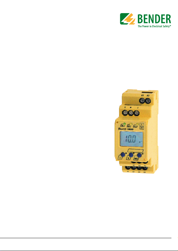
CME420
Multi-functional current relay, AC,
overcurrent/undercurrent/
window discriminator function
CME420_D00034_00_M_XXEN/07.2013
Page 2

Bender GmbH & Co. KG
Londorfer Str. 65 • 35305 Gruenberg • Germany
Postfach 1161 • 35301 Gruenberg • Germany
Tel.: +49 6401 807-0
Fax: +49 6401 807-259
E-Mail: info@bender-de.com
Web: http://www.bender-de.com
© Bender GmbH & Co. KG
All rights reserved.
Reprinting only with permission
of the publisher.
Subject to change!
Page 3

Table of Contents
1. How to use this documentation effectively ................................................ 5
1.1 How to use this manual ................................................................................. 5
1.2 Symbols ............................................................................................................... 5
1.3 Intended use ...................................................................................................... 6
1.4 Information about factory setting ............................................................. 6
2. Safety information ........................................................................................... 7
2.1 Safety instructions ........................................................................................... 7
2.2 Work activities on electrical installations ................................................ 7
3. Function ............................................................................................................. 9
3.1 Device features ................................................................................................. 9
3.2 Function ............................................................................................................... 9
3.2.1 Automatic self test ........................................................................................ 10
3.2.2 Manual self test .............................................................................................. 10
3.2.3 Malfunction ..................................................................................................... 10
3.2.4 Specify the number of reload cycles ...................................................... 11
3.2.5 Erasable history memory ............................................................................ 11
3.2.6 Assigning alarms to the alarm relays K/1K2 ........................................ 11
3.2.7 Residual current monitoring in window discriminator mode ...... 11
3.2.8 Time delays t, ton and toff ......................................................................... 12
3.2.9 Password protection (on, OFF) ................................................................. 12
3.2.10 Factory setting FAC ...................................................................................... 12
3.2.11 Display accuracy ............................................................................................ 12
4. Installation and connection ......................................................................... 13
5. Operation and setting ................................................................................... 15
5.1 Used display elements ................................................................................ 15
5.2 Function of the operating elements ...................................................... 16
CME420_D00034_00_M_XXEN/07.2013
3
Page 4

Table of Contents
5.3 Menu structure ............................................................................................... 17
5.4 Display in standard mode ......................................................................... 18
5.5 Display in menu mode ................................................................................ 19
5.5.1 Parameter query and setting: overview ................................................ 19
5.5.2 Switching over from overcurrent to undercurrent operation or to
window operation ......................................................................................... 21
5.5.3 Response value setting for overcurrent: ............................................... 22
5.5.4 Setting the fault memory and operating principle of the alarm
relays .................................................................................................................. 23
5.5.5 Assigning alarm categories to the alarm relays ................................. 24
5.5.6 Setting the time delays ............................................................................... 26
5.5.7 Changing from overcurrent operation to window operation ...... 27
5.5.8 Setting the transformation ratio for external current transformer ...
28
5.5.9 Re-establishing the factory settings ....................................................... 30
5.5.10 History memory query ................................................................................. 30
5.6 Commissioning .............................................................................................. 31
5.7 Factory setting ............................................................................................... 31
5.8 Timing diagram: Current monitoring ..................................................... 32
6. Technical data ................................................................................................ 33
6.1 Data in tabular form ..................................................................................... 33
6.2 Ordering information ................................................................................... 36
4
CME420_D00034_00_M_XXEN/07.2013
Page 5
1. How to use this documentation effectively
1.1 How to use this manual
This manual is intended for experts in electrical engineering and electronics!
This manual describes the multi-functional current relay CME420. It must be
kept ready for referencing in the immediate vicinity of the device.
1.2 Symbols
In order to make it easier for you to find specific text passages or references in
this manual and for reasons of comprehensibility, important information is
emphasized by symbols. The meaning of these symbols is explained below:
The warning symbol indicates a potential dangerous situation that may result in bodily injury and/or damage to
property.
Observe the associated safety instructions!
Information intended to assist the user to make optimum
use of the product are marked with the Info symbol.
CME420_D00034_00_M_XXEN/07.2013
5
Page 6

How to use this documentation effectively
1.3 Intended use
The current monitor is designed to monitor the threshold values of AC currents for overcurrent and undercurrent conditions. In case of direct measurement, currents up to 16 A (screw-type terminals) resp. 12 A (push-wire
terminals) can be continuously monitored. For indirect measurement by
means of a current transformer, a transformation ratio factor up to 2000 can
be set. The device allows pure overcurrent and pure undercurrent operation,
as well as window operation between two adjustable response values. The
device is factory set to overcurrent operation.
1.4 Information about factory setting
The page 31 provides a summary of all factory settings.
If you want to reset the current monitor to factory settings refer to page 30.
6
CME420_D00034_00_M_XXEN/07.2013
Page 7

2. Safety information
2.1 Safety instructions
In addition to this data sheet, the documentation of the device includes a
sheet entitled "Important safety instructions for BENDER products“.
2.2 Work activities on electrical installations.
Danger of electric shock!
Touching live parts will cause danger of electric shock
with fatal consequences. All work activities on electrical
installations as well as installation activities, commissioning activities and work activities with the device in
operation may only be carried out by electrically skilled
persons!
Observe the relevant regulations applying to work on electrical instal-
lations, in particular DIN EN 50110 or its subsequent regulation
If the equipment is used outside the Federal Republic of Germany, the
respective national standards and regulations are to be observed. The
European standard EN 50110 is recommended to be used as a directive.
CME420_D00034_00_M_XXEN/07.2013
7
Page 8

Safety information
8
CME420_D00034_00_M_XXEN/07.2013
Page 9

3. Function
3.1 Device features
Undercurrent or overcurrent monitoring in AC systems, < I or > I and
current monitoring with window discriminator function
Indirect current monitoring by means of a current transformer,
suitable for transformation ratio factor 1…2000
Adjustable switching hysteresis
r.m.s. value measurement AC
Continuous self monitoring
Starting delay, response delay and delay on release
Measured value display via multi-functional LC display
Alarm indication via LEDs (AL1, AL2) and changeover contacts (K1, K2)
N/C operation or N/O operation selectable
Fault memory behaviour selectable
Password protection against unauthorized parameter changing
Sealable transparent cover
Two-module enclosure (36 mm)
With push-wire terminals: two terminals per connection
3.2 Function
Once the supply voltage is applied, the starting delay "t" is activated. Measured values changing during this time do not influence the switching state of
the alarm relays.
The devices provide two separately adjustable measuring channels (overcurrent/undercurrent). When the measured value exceeds (ALARM 1) resp. drops
below (ALARM 2) the adjusted threshold value, the time of the response delays "t
switch and the alarm LEDs light. If the measured value falls below or exceeds
" begins. After the expiry of the response delay, the alarm relays
on 1/2
CME420_D00034_00_M_XXEN/07.2013
9
Page 10

Function
the adjusted delay on release (response value plus hysteresis) after the alarm
relays have switched, the delay on release starts "t
the alarm relays switch back to their initial position. With activated fault mem-
". After the expiry of "t
off
off“,
ory, the alarm relays do not change their actual state until the reset button R
is pressed.
3.2.1 Automatic self test
The device automatically carries out a self test after connecting to the system
to be monitored and later every 24 hours. During the self test internal functi onal fau lts o r co nnec tio n fau lts will be d eter min ed an d wi ll a ppea r in form of
an error code on the display. The alarm relays are not checked during this test.
3.2.2 Manual self test
After pressing the internal test button for > 1.5 s, a self test is performed by the
device. During this test, internal malfunctions will be determined and appear
in form of an error code on the display. The alarm relays are not checked during this test.
While the test button T is pressed and held down, all device-related display elements appear on the display.
3.2.3 Malfunction
In the event of an internal malfunction, all three LEDs flash. An error code appears on the display (E.02…E.32).
Error code Meaning Action
E.02
E.03…E.32
10
Fault occured
during manual self test
Check device connection. After eliminating the fault, the error code will be automatically deleted.
Carry out a reset. Reset the device to factory setting. After eliminating the fault,
the error code will be automatically
deleted.
CME420_D00034_00_M_XXEN/07.2013
Page 11

Function
If the fault continues to exist, please contact the Bender Service.
3.2.4 Specify the number of reload cycles
If faults occur only temporarily, but recurrently, in the system being monitored, with deactivated fault memory M, the alarm relays would switch synchronously to the error status.
RL in the out menu can be used to limit the number of these changeover processes. As soon as the specified number of processes is exceeded, the fault
memory will come on and an activated alarm remains stored.
3.2.5 Erasable history memory
The first alarm value that occurs will be entered in this memory. The memory
can be cleared via the menu HiS.
3.2.6 Assigning alarms to the alarm relays K/1K2
Different alarm categories can be assigned to the alarm relays K1/K2 via the
menu "out".
3.2.7 Residual current monitoring in window discriminator mode
Change the measuring principle by selecting the window mode (SEt / In). In
the window discriminator mode, the threshold values I1 and I2 represent the
upper and the lower value. If the measured value is not within this area, an
alarm is initiated by the device (see page 27).
CME420_D00034_00_M_XXEN/07.2013
11
Page 12

Function
3.2.8 Time delays t, ton and t
The times t, ton and t
described below delay the output of alarms via LEDs
off
off
and relays.
Starting delay t
After connection to the supply voltage U
, the alarm indication is delayed by
S
the preset time t (0…300 s).
Response delay t
If the current value exceeds or falls below the threshold value, the current
monitor does not initiate an alarm before the response time t
A set response delay t
time t
and delays alarm signalling (total delay time tan = tae + ton).
ae
on1/2
(0… 300 s ) add s up to the d evic e-rel ated oper ating
on1/2
has elapsed.
an
If the fault does not continue to exist before the time of the response delay has
elapsed, an alarm will not be indicated.
Release delay t
off
When no alarm exists after deactivating the fault memory, the alarm LEDs will
go out and the alarm relays switch back to their initial position. After activating the release delay (0…300 s), the alarm state is continuously maintained for
the selected period.
3.2.9 Password protection (on, OFF)
With activated password protection (on), settings can only be carried out
when the correct password (0…999) has been entered.
3.2.10 Factory setting FAC
After activating the factory setting, all settings previously changed are reset to
delivery status.
3.2.11 Display accuracy
The display accuracy of the measured current values depends on the set response values. When an alarm response value I2 of 10 A has been selected,
currents smaller than 350 mA are displayed as < 0.3 A.
12
CME420_D00034_00_M_XXEN/07.2013
Page 13

4. Installation and connection
90 mm
45
67,5
36 mm
31,1
47,5
70,5
100 mm
116 mm
Zubehör/
Accessory
Ensure safe isolation from supply in the installation area.
Observe the installation rules for live working!
Dimension diagram and drawing for screw fixing
The front plate cover is easy to open at the lower part identified by an arrow.
CME420_D00034_00_M_XXEN/07.2013
13
Page 14

1. DIN rail mounting:
U
s
A1
~/
~/+
6A 6A
IT-System
A2
kl
11 1412
21 2422
A2A1
lk
L1
N
lk
L1
N
Snap the rear mounting clip of the device into place in such a way that
a safe and tight fit is ensured.
Screw fixing:
Use a tool to move the rear mounting clips (a second mounting clip
required, see ordering information) to a position that it projects over
the enclosure. Then fix the device using two M4 screws.
2. Wiring
Connect the device according the wiring diagram.
Ter m in al Co nn ec t io ns
A1, A2
k, l
11, 12, 14 Alarm relay K1
21, 22, 24 Alarm relay K2
14
Installation and connection
Connection to supply voltage U
s
Connection to the conductor to be monitored: directly or
by means of a current transformer
CME420_D00034_00_M_XXEN/07.2013
Page 15

5. Operation and setting
5.1 Used display elements
A detailed description of the meaning of the display elements is given in the
table below.
Used display elements
CME420_D00034_00_M_XXEN/07.2013
Elemen
t
Func tion
RL Reload function with memory = off
(L = I.)
n Transformation ratio factor for
external current transformer
<I
Undercurrent
>I
Overcurrent
r1, 1
Alarm relay K1,
r2, 2
Alarm relay K2
I Hys,
Response value hysteresis in %
%
Response delay t
ton1,
ton2,
Response delay t
t,
Starting delay t,
toff
Delay on release t
M
Fault memory active
Operating mode of the relays K1, K2
Password protection active
(K1),
on1
(K2)
on2
for K1, K2
off
15
Page 16

5.2 Function of the operating elements
ON AL1 AL2
T MENUR
Operation and setting
Device front
Elemen
t
Func tion
ON Power On LED, green
AL1,
LED Alarm 1 lights (yellow):
Response value 1 reached
AL2
LED Alarm 2 lights (yellow):
Response value 2 reached
1,6 A,MI = 1.6 A flow via
the terminals k and l,
Fault memory active
T, Test button (> 1.5 s):
Indication of the display elements,
starting a self test;
Up key (< 1.5 s):
Menu items/values
R, Reset button (> 1.5 s):
Deleting the fault memory;
Down key (< 1.5 s):
Menu items/values
MENU, MENU key (> 1.5 s):
Starting the menu mode;
Enter key (< 1.5 s):
Confirm menu item, submenu item
and value.
Enter key (> 1.5 s):
Back to the next higher menu level.
16
CME420_D00034_00_M_XXEN/07.2013
Page 17

Operation and setting
5.3 Menu structure
All adjustable parameters are listed in the columns menu item and adjustable
parameters. A display-like representation is used to illustrate the parameters
in the column menu item. Different alarm categories can be assigned to the
alarm relays K1, K2 via the submenus r1, r2. This is done by activation or deactivation of the respective function.
Menu
AL
(response values)
Sub
menu
out
(output control)
r1
(K1: (assignment alarm
category)
r2
(K2: (assignment alarm
category)
t
(timing
check)
CME420_D00034_00_M_XXEN/07.2013
Menu
item
> I2 ON (HI) Overcurrent (alarm)
> I1 ON (HI)
Hys Hysteresis < I21, > I21
M ON Fault memory
RL
1 Err ON Device error at K1
r1 I1 ON Prewarning I1 at K1
r1 I2 OFF Alarm I2 at K1
1 tES ON Device test
2 Err ON Device error at K2
r2 I1 OFF Prewarning I1 at K2
r2 I2 ON Alarm I2 at K2
2 tES ON Device test
t on 1 - Response delay K1
t on 2 - Response delay K2
T- Starting delay
t off - Delay on release K1/K2
Activation Adjustable parameter
Overcurrent (prewarning)
1
- Operat. mode K1 (n.c.)
2
- Operat. mode K2 (n.c.)
Reload function (memory = off )
17
Page 18

Operation and setting
Menu
Set
(device control)
InF -
HiS Clr -
Sub
menu
Menu
item
I 12 HI
n1
FAC -
SYS - Function blocked
Activation Adjustable parameter
Setting ranges:
High, window function,
low
Transformation ratio
factor external current
transformer
OFF
Parameter setting via
password
Re-establish factory
settings
Display hard / software
version
History memory for the
first alarm value, erasable
5.4 Display in standard mode
By default, the currently measured current is displayed or, if required, the
measured overcurrent value. The current response values (prewarning) and
I2 (alarm) can be displayed using the Up and Down key. If you want to return to the measured value, press the Enter key.
18
CME420_D00034_00_M_XXEN/07.2013
Page 19

Operation and setting
5.5 Display in menu mode
5.5.1 Parameter query and setting: overview
Menu
Adjustable parameter
item
Response values query and setting:
– Alarm I2 (AL2), (undercurrent, overcurrent or window
AL
Configuration of the fault memory and the alarm relays:
out
Delay settings:
T
Parameter setting for device control:
SEt
InF Query hard and software version
HiS Query the first stored alarm value
ESC Move to the next higher menu level (back)
function can be set in the SEt/I menu)
– Prewarning I1 (AL1), (50 % of I2)
– Specify the hysteresis of the response values: Hys I12
– Activating/deactivating the fault memory
– Select N/O operation (n.o.) or N/C operation (n.c.)
individually for each K1/K2
– Specify the number of the reload cycles
– Assign the alarm categories undercurrent or overcurrent
or device error individually to each K1/K2 (1, r1 / 2, r2).
– Response delay t
– Starting delay t
– Delay on release t
on1/ton2
(LED, relay)
off
– Select the appropriate parameter for response values:
High (HI), low (Lo) or window function (In).
– Set the transformation ratio (n) for the current transformer
– Enable or disable password protection, change the pass-
word
– Re-establish factory settings
– Service menu SyS blocked
CME420_D00034_00_M_XXEN/07.2013
19
Page 20

Menu structure
t < 1,5 s
t >1,5 s
t > 1,5 s
t > 1,5 s
t < 1,5 s
AL
out
t
SEt
InF
HiS
ESC
ESC
Operation and setting
20
CME420_D00034_00_M_XXEN/07.2013
Page 21

Operation and setting
Parameter settings
An example is given below on how to change the alarm response value for
overcurrent > I1. It is presumed that the option overcurrent (HI) has been selected in the SEt/I menu (factory setting). Proceed as follows:
1. Press the MENU/Enter key for more than 1.5 seconds. The flashing short
symbol AL appears on the display.
2. Confirm with Enter. The parameter response value I2 flashes, in addition the associated overcurrent value > 10.0 A appears.
3. Use the Down key to select the parameter response value I1. The
parameter I1 flashes, in addition the associated percentage value for
prewarning 50 % of I2 appears.
4. Confirm with Enter. The current value for prewarning appears on the
flashing display.
5. Use the Up or Down key to set the appropriate response value. Confirm
with Enter. I1 flashes.
6. You can exit the menu by:
– Pressing the Enter key for more than 1.5 seconds to reach the next
higher level or
– selecting the menu item ESC and confirming with Enter to reach the
next higher level.
The currently active segments are flashing! In the figures below, the
segments where device settings can be carried out are highlighted
by an oval. The menu mode can be reached by pressing the MENU
key for more than 1.5 seconds.
5.5.2 Switching over from overcurrent to undercurrent operation or to window operation
The operating mode can be selected in the SEt/I menu using the parameters
HI, Lo and In. By default, overcurrent operation (HI) is set. Refer to page 27 for
a detailed description on how to switchover to the window mode.
CME420_D00034_00_M_XXEN/07.2013
21
Page 22

Operation and setting
1x
2x
5.5.3 Response value setting for overcurrent:
- Response value I2 (overcurrent)
- Response value I1 (overcurrent)
- Hysteresis (Hys) of the response values I1, I2
Increasing the response value I2 (Example: overcurrent)
Increasing the response value I1 (prewarning overcurrent
Setting the hysteresis of the response value
22
CME420_D00034_00_M_XXEN/07.2013
Page 23

Operation and setting
1x
2x
>1,5 s
3x
5.5.4 Setting the fault memory and operating principle of the alarm relays
Deactivating the fault memory
Setting the alarm relay K1 to N/O operation (n.o.)
Setting the number of reload cycles
CME420_D00034_00_M_XXEN/07.2013
23
Page 24

Operation and setting
3x
>1,5 s
4x
4x
3x
>1,5 s
1x
5.5.5 Assigning alarm categories to the alarm relays
Overcurrent, undercurrent and device-related errors of the current monitor
can be assigned to the alarm relays K1 (r1, 1) and K2 (r2, 2). By default, the
alarm relays K1 and K2 signal prewarning and alarm in case of overcurrent.
Alarm relay K1: Deactivating the category device error
Alarm relay K1: Deactivating the category response value I1
24
CME420_D00034_00_M_XXEN/07.2013
Page 25

Operation and setting
4x
3x
>1,5 s
2x
4x
3x
>1,5 s
3x
Alarm relay K1: Activating the category response value I2
Alarm relay K1: Deactivating the category device test
.
When an alarm relay (K1/K2) has been deacti vated in the
menu, an alarm will not be signalled by the respective
changeover contact! An alarm will only be indicated by
the respective alarm LED (AL1/AL2)!
CME420_D00034_00_M_XXEN/07.2013
25
Page 26

Operation and setting
3x
>1,5 s
5.5.6 Setting the time delays
The following delays can be specified:
Response delay t
Starting delay t (0…10 s) when the device is being started
Common delay on release t
only relevant when the fault memory M is deactivated.
(0…300 s) for K1, and t
on1
(0…300 s) for K1, K2. The setting t
off
(0…300 s) for K2
on2
is
off
The operating steps for the setting of the response delay t
delay t are illustrated by way of example.
Setting the response delay t
26
on1
CME420_D00034_00_M_XXEN/07.2013
and the starting
on1
Page 27

Operation and setting
2x
>1,5 s
2x
2x
>1,5 s
Setting the starting delay t
5.5.7 Changing from overcurrent operation to window operation
Use this menu item to set whether the response values of the device apply to
overcurrent (HI) or undercurrent operation (Lo). In addition, window operation (In) can be selected. .
CME420_D00034_00_M_XXEN/07.2013
27
Page 28

Operation and setting
2x
>1,5 s
1x
2x
>1,5 s
2x
5.5.8 Setting the transformation ratio for external current transformer
Factory setting and password protection
Use this menu to activate the password protection, to change the password
or to deactivate the password protection. In addition, you can reset the device
to its factory settings.
a) Activating the password protection
28
CME420_D00034_00_M_XXEN/07.2013
Page 29

Operation and setting
2x
>1,5 s
2x
2x
>1,5 s
2x
b) Changing the password
c) Deactivating the password protection
CME420_D00034_00_M_XXEN/07.2013
29
Page 30

Operation and setting
3x
....
.... ....
5.5.9 Re-establishing the factory settings
Device information query
This function is used to query the hardware (d…) and software (1.xx) versions.
After activating this function, data will be displayed as a scrolling text. Once
one pass is completed you can select individual data sections using the Up/
Down keys.
5.5.10 History memory query
The history memory can be selected via the menu HiS. Use the Up and Down
keys to view the next display. If Clr is flashing, the history memory can be
cleared by pressing the Enter key.
30
CME420_D00034_00_M_XXEN/07.2013
Page 31

Operation and setting
5.6 Commissioning
Prior to commissioning, check proper connection of the current relay.
Danger of fire!
Please note the maximum permissible measuring current
continuously applied is in case of direct measurement:
Push-wire terminals: 12 A
Screw-type terminals: 16 A
5.7 Factory setting
Response value overcurrent I1 (prewarning)
Response value overcurrent I2 (alarm)
Hysteresis:
Fault memory M:
Operating mode K1/K2
Starting delay:
Response delay:
Release delay:
Password:
CME420_D00034_00_M_XXEN/07.2013
5 A (50 % of I2)
10 A
15 %
activated (on)
N/C operation (n.c.)
t = 0,5 s
t
= 1 s
on1
t
= 0 s
on2
t
= 1 s
off
0, deactivated (Off)
31
Page 32

5.8 Timing diagram: Current monitoring
t
an
Strom/
Current
> I
Hys
Hys
< I
t
t
an
t
off
Unterstrom/
Undercurrent
Überstrom/
Overcurrent
Dt < t
an
Dt
Start
Dt
t
an
t
an
t
off
Dt < t
an
U
S
ON
AL1
AL2
Versorgungsspannung/
Supply voltage
Alarm-LEDs
Alarm relays
Arbeitsstrom/ N/O
MEM off
Alarm relays
Ruhestrom/ N/C
MEM off
11 - 12
21 - 22
Alarm relays
Arbeitsstrom/ N/O
MEM on
Alarm relays
Ruhestrom/ N/C
MEM on
14
24
11 - 12
21 - 22
14
24
11 - 12
21 - 22
14
24
11 - 12
21 - 22
14
24
Operation and setting
t = Starting delay, tan = Response time, t
32
= Delay on release
off
CME420_D00034_00_M_XXEN/07.2013
Page 33

6. Technical data
6.1 Data in tabular form
( )* = factory setting
Insulation coordination acc. to IEC 60664-1/IEC 60664-3
Rated insulation voltage ....................................................................................................................................... 250 V
Rated impulse voltage/overvoltage category..................................................................................................... 4kV / III
pollution degree .............................................................................................................................................................3
Protective separation (reinforced insulation) between.......................... (A1, A2) - (k, l) - (11, 12, 14) - (21, 22, 24)
Maximum nominal voltage of the system being monitored
when the conductor being monitored is directly connected:
With protective separation............................................................................................................................... AC 230 V
Without protective separation ......................................................................................................................... AC 400 V
Supply voltage
CME420-D-1:
Supply voltage U
Frequency range U
CME420-D-2:
Supply voltage U
Frequency range U
Power consumption ............................................................................................................................................ ≤ 4 VA
Measuring circuit
Measuring range (r.m.s. value, screw-type terminal) ........................................................................ AC 0.05…16 A
Measuring range (r.m.s. value, push-wire terminal) .......................................................................... AC 0.05…12 A
Overload capability < 1 s ....................................................................................................................................... 40 A
Rated frequency f
......................................................................................................... AC 16…72 V / DC 9.6…94 V
s
................................................................................................................................... 42…460 Hz
s
............................................................................................................................. AC/DC 70…300 V
s
................................................................................................................................... 42…460 Hz
s
.................................................................................................................................... 42…460 Hz
n
CME420_D00034_00_M_XXEN/07.2013
33
Page 34

Technical data
Response values
Undercurrent
Undercurrent< I (alarm I
Push-wire terminal...................................................................................................................... AC 0.1…12 A (1 A)*
), direct connection:
2
Screw-type terminal.................................................................................................................... AC 0.1…16 A (1 A)*
or external current transforme r
Undercurrent < I (prewarning I
) .................................................................................... 100 %…200 % (150 %)*
1
Overcurrent
Overcurrent > I (alarm I
Push-wire terminal...................................................................................................................... AC 0.1…12 A (1 A)*
), direct connection:
2
Screw-type terminal.................................................................................................................... AC 0.1…16 A (1 A)*
or external current transforme r
Overcurrent > I (prewarning I
) ........................................................................................... 10 %…100 % (50 %)*
1
Others
External current transformer........................................................................................................... x/1 A, x/5 A, x/10 A
Transformation ratio factor n ..................................................................................................................1…2000 (1)*
Relative percentage error at 50 Hz / 60 Hz.......................................................................................... ±3 %, ±2 digits
Relative percentage error in the range of 42…2000 Hz.................................................................... ±5 %, ±2 digits
Hysteresis ....................................................................................................................................... 10…40 % (15 %)*
Specified time
Starting delay ................................................................................................................................... 0…300 s (0.5 s)*
Response delay t
Response delay t
Delay on release t
Operating time t
Response time t
Recovery time tb ............................................................................................................................................. ≤ 300 ms
............................................................................................................................ 0…300 s (1 s)*
on1
............................................................................................................................ 0…300 s (0 s)*
on2
............................................................................................................................. 0…300 s (1 s)*
off
............................................................................................................................................ ≤ 70 ms
ae
.............................................................................................................................. tan = tae + t
an
on1/2
Displays, memory
Display..................................................................................................... LC display, multi-functional, not illuminated
Measuring range measured value x transformation ratio factor.................................................... AC 0.01…16 A x n
Operating error at 50 Hz / 60 Hz .......................................................................................................... ±3 %, ±2 digits
Operating error in the range of 42…2000 Hz.................................................................................... ±5 %, ±2 digits
Measured-value memory (HiS) for the first alarm value................................................ data record measured values
34
CME420_D00034_00_M_XXEN/07.2013
Page 35

Technical data
Password ........................................................................................................................................ Off / 0…999 (Off)*
Fault memory (M) alarm relay ................................................................................................................. on / off (on)*
Switching elements
Number ....................................................................................... 2 relays, with one changeover contact each (K1, K2)
Operating principle...................................................... N/C operation n.c. / N/O operation n.o. (N/C operation n.c.)*
Electrical service life under rated operating conditions.................................................... 10000 switching operations
Contact data acc. to IEC 60947-5-1:
Utilization category ............................................................ AC-13 ........ AC-14........ DC-12........ DC-12....... DC-12
Rated operational voltage .................................................. 230 V ......... 230 V ........... 24 V......... 110 V ....... 220 V
Rated operational current ........................................................ 5 A ............. 3 A ............. 1 A.......... 0.2 A ........ 0.1 A
Minimum contact load................................................................................................................1 mA at AC/DC ≥ 10 V
Environment/EMC
EMC .................................................................................................................................................................. IEC 61326
Operating temperature ..................................................................................................................... –25 ºC…+55 ºC
Classification of climatic conditions acc. to IEC 60721:
Stationary use (IEC 60721-3-3) ........................................................ 3K5 (except condensation and formation of ice)
Transportation (IEC 60721-3-2) ........................................................2K3 (except condensation and formation of ice)
Storage (IEC 60721-3-1) ...................................................................1K4 (except condensation and formation of ice)
Classification of mechanical conditions acc. to IEC 60721:
Stationary use (IEC 60721-3-3) .............................................................................................................................. 3M4
Transportation (IEC 60721-3-2) .............................................................................................................................. 2M2
Storage (IEC 60721-3-1) ......................................................................................................................................... 1M3
Connection
Connection ............................................................................................................................. screw-type terminals
Connection properties:
rigid/ flexible ............................................................................................. 0.2…4 / 0.2…2.5 mm
Multi-conductor connection (2 conductors with the same cross section):
rigid/ flexible ............................................................................................................ 0.2…1.5 mm
2
/ AWG 24…12
2
/ 0.2…1.5 mm
Stripping length ............................................................................................................................................ 8…9 mm
Tightening torque..................................................................................................................................... 0.5…0.6 Nm
Connection ............................................................................................................................... push-wire terminals
Connection properties:
rigid .............................................................................................................0.2…4 / 0.2…2.5 mm
2
/ AWG 24…14
2
CME420_D00034_00_M_XXEN/07.2013
35
Page 36

Technical data
flexible without ferrule .............................................................................. 0.2…4 / 0.2…2.5 mm2 / AWG 24…14
flexible with ferrule..................................................................................................... 0.2…1.5 mm
2
/ AWG 24…16
Stripping length ...................................................................................................................................................10 mm
Opening force........................................................................................................................................................... 50 N
Test opening, diameter .......................................................................................................................................2.1 mm
Other
Operating mode ........................................................................................................................... continuous operation
Position ........................................................................................................................................................ any position
Degree of protection DIN EN 60529, internal components..................................................................................... IP30
Degree of protection DIN EN 60529, terminals........................................................................................................IP20
Enclosure material ....................................................................................................................................polycarbonate
Flammability class ........................................................................................................................................... UL94 V-0
DIN rail mounting acc. to.................................................................................................................................IEC 60715
Screw fixing ......................................................................................................................... 2 x M4 with mounting clip
Weight ............................................................................................................................................................... ≤ 160 g
( )* = factory setting
6.2 Ordering information
Device type
CME420-D-1
(push-wire terminal)
CME420-D-1
(screw-type terminal)
CME420-D-2
(push-wire terminal)
CME420-D-2
(screw-type terminal)
Supply voltage U
DC 9.6 V…94 V /
AC 42…460 Hz, 16…72 V
DC 9.6 V…94 V /
AC 42…460 Hz, 16…72 V
DC 70…300 V /
AC 42…460 Hz, 70…300 V
DC 70…300 V /
AC 42…460 Hz, 70…300 V
*Absolute values of the voltage range
Mounting clip for screw fixing
(1 piece per device, accessories)
*
s
Response value Art. No.
0.1…12 A x n B 7306 0001
0.1…16 A x n B 9306 0001
0.1…12 A x n B 7306 0002
0.1…16 A x n B 9306 0002
B 9806 0008
36
CME420_D00034_00_M_XXEN/07.2013
Page 37

INDEX
A
Adjustable parameters, list 17
Automatic self test
D
Deleting the fault alarms 16
Device features
Display in standard mode
E
Enter key 16
Example of parameter setting
F
factory setting 12, 31
Function
10
9
18
9
21
10
alarm value)
16
5
18
18
17
17
LED Alarm 2 lights
M
Malfunction 10
Manual self test
Manual, target group
Menu
- AL (response values)
- HiS (history memory for the first
- InF (hard and software version)
- out (output control)
- Set (device control
- t (timing check)
Menu structure, overview
Mounting clip for screw fixing
17
18
17
36
H
How to use this manual 5
I
Installation and connection 13
K
K1: assignment alarm category 17
K2: assignment alarm category
L
LED Alarm 1 lights 16
CME420_D00034_00_M_XXEN/07.2013
17
O
Operating elements, function 16
Operation and setting
Ordering information
P
Parameter query and setting, overview 19
Parameter setting
- Activating or deactivating the pass-
word protection
- Assigning alarm categories to the
alarm relays
15
36
28
24
37
Page 38

- Changing from overcurrent operation to window operation
- Deactivating the fault memory
- Response value setting
- Setting the time delay
Password protection
R
Release delay toff 12
Reset button
Response delay ton
Response value setting
- Hysteresis
- Overcurrent (> I)
S
Setting the number of reload cycles 23
Starting delay t
Starting the menu mode
T
Technical data 33
Test button
U
Used display elements 15
W
Wiring diagram 14
Work activities on electrical installations
12
16
12
22
12
16
27
22
26
22
16
23
7
38
CME420_D00034_00_M_XXEN/07.2013
Page 39

Page 40

D0003400MXXEN
Bender GmbH & Co. KG
Londorfer Str. 65 • 35305 Gruenberg • Germany
Postfach 1161 • 35301 Gruenberg • Germany
Tel.: +49 6401 807-0
Fax: +49 6401 807-259
E-Mail: info@bender-de.com
Web: http://www.bender-de.com
 Loading...