

Bender CC612 -1M4PR, CC612 -2M4PR, CC612 -1S0PR, CC612 -2S0PR, CC612 -2M4R Quick Start Manual
...Page 1
CC612 EV charge controller
Charge controller for electric vehicle charging stations, wall boxes and
street light charging points
Quickstart ENCC612(4G)_D00325_05_Q_XXEN / 10.2019
Page 2
CC612 EV charge controller
Information!
i
Read the corresponding manual in addition to this quickstart.
Downloadable at: www.bender.de/en/service-support/downloads
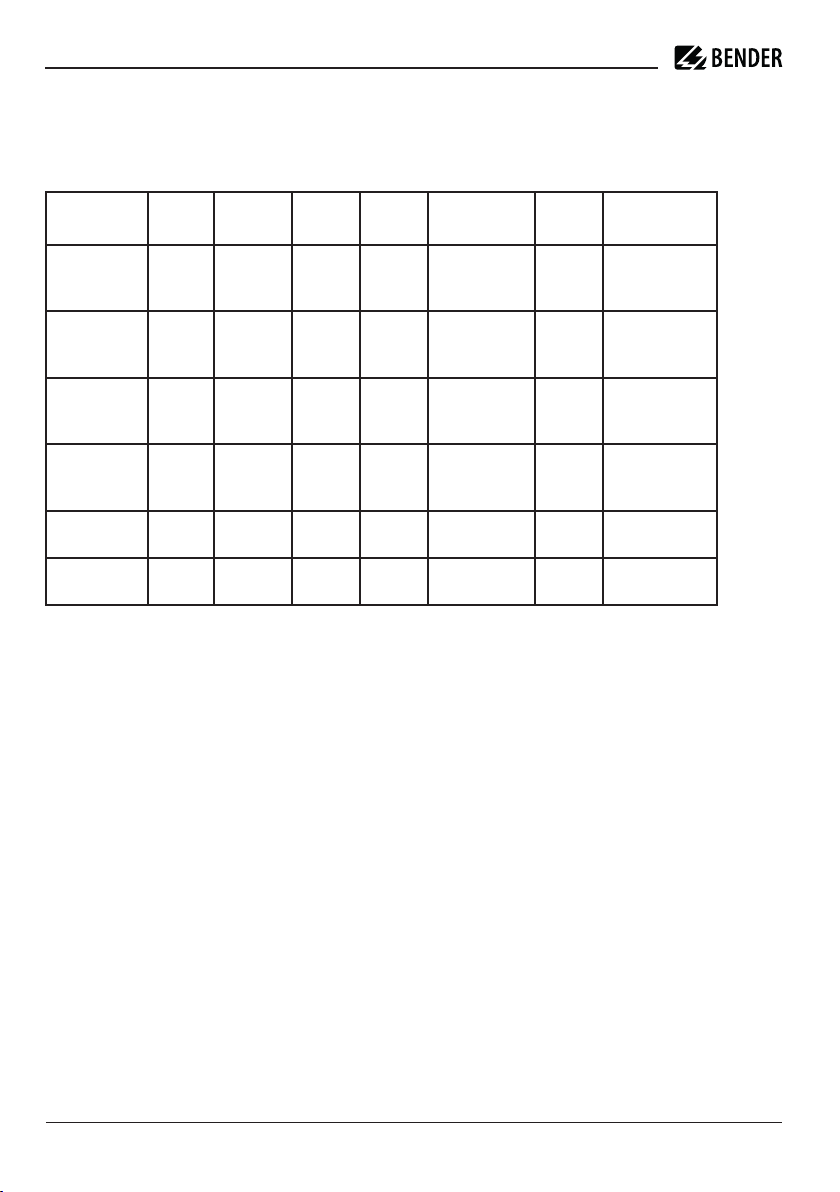
Type of device Modem Meter RDC-MD* PLC**
CC612 -1M4PR 4G eHZ, S0
interface
CC612 -2M4PR 4G Modbus, S0
interface
CC612 -1S0PR --- eHZ, S0
interface
CC612 -2S0PR --- Modbus, S0
interface
CC612 -2M4R 4G Modbus, S0
interface
CC612 -2S0R --- Modbus, S0
interface
hardware
ü ü ü
ü ü ü
ü ü ü
ü ü ü
ü
ü
---
---
User
interface
ü
ü
LEDs Art. No.
Ready,
Alarm,
PLC
Ready,
Alarm,
PLC
Ready,
Alarm,
PLC
Ready,
Alarm,
PLC
Ready,
Alarm
Ready,
Alarm
B94060011
B94060013
B94060005
B94060007
B94060015
B94060010
Intended use
The CC612 charge controller is the main component of a charge system and is designed for use in
electric vehicle (EV) charging stations, wall boxes and street light charging points. The charge
controller supports type 1 and type 2 plugs, and type 1 and type 2 sockets. It enables a setup that
is in accordance with current standards, such as IEC 61851-1, IEC 61851-22 and IEC 60364-7-722.
Any use other than that described in this quick-start guide is regarded as improper.
2 CC612(4G)_D00325_05_Q_XXEN / 10.2019
Page 3
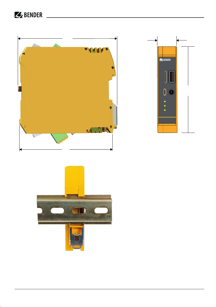
Dimensions and installation
CC612 EV charge controller
115,13
107
22,60
CC612
USB 1
SIM
98,54
CONFIG
ALARM
READY
PLC
Note: All dimensions are in mm and are according to ISO 2768-m.
CC612(4G)_D00325_05_Q_XXEN / 10.2019 3
Page 4
–
+
IN
M
–
+
A
CP
PP
PE
N L1
L2
L3
e
L1
L2
L3
N
PE
PP
CP
PE
L1 N
L3
L2
f
12V 0V 11 14
B
1
2
3
4
5
6
D
C
IN +
OUT
–
A
RJ10
F
RJ45
E
CC612
ALARM
READY
PLC
USB 1
SIM
CONFIG
B
A
PP
IN1–
IN2–
21
IN1+
IN2+
CP
24
C
IN2–
IN2+
n
IN1–
IN1+
m
21
24
j
PP
CP
g
h
c
14
11
0V
12V
i
AC
DC
0 V
12 V
b
d
H
V
a
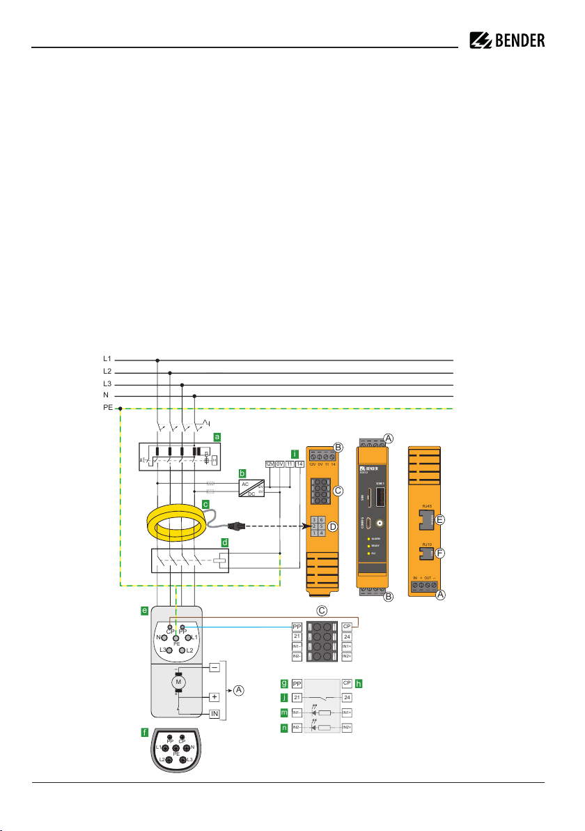
Connection
Danger! Risk of electric shock!
Parts of the system can be energised (the charge controller terminals up to 12 V, the charging
I
system voltage is 230 V). Before touching live parts of the system, ensure that the installation
has been de-energised.
The RJ45 user interface is not intended as an Ethernet interface.
i
The use of Nano SIM cards with a corresponding SIM card adapter may damage the SIM card
i
slot.
Therefore, it is recommended to use only Micro SIM cards.
Further information on the connection can be found in the manuals of the accessories (e.g.
i
W15BS).
• Connect PE to „0V“; reference level for Control Pilot (CP communication) must be at same level
as the power supply (IEC 61851 standard).
• Cable lengths (except Modbus, Power IN and charging cable) < 3 m; cables must be positioned
inside the wallbox/charging station and should not be laid parallel to power cables.
• Modbus (A, B) must be connected using a shielded cable; connect shield to PE.
4 CC612(4G)_D00325_05_Q_XXEN / 10.2019
Bottom view
Frontal view
Top view
Page 5

CC612 EV charge controller
Legend
A Connector Current Transformer (CT) d Contactor
B Connector User Interface e Type 2 socket*
C Connector f Type 2 plug*
D Connection Current Transformer (CT) g Control pin (contactor)
E Connection User Interface (RJ45) h PLC (optional) via this terminal
F Connection Modbus/eHZ meter (RJ10) i Relay output 1
a RCD Type A j Relay output 2
b Rectifier m Optocoupler input 1
c Current Transformer (with plug) n Optocoupler input 2
Other ways of connecting the charge controller can be found in the operating manual.
Terminal assignment
A1 IN C1 PP
A2 + C2 CP
A3 OUT C3 21
A4 - C4 24
B1 12V C5 IN1-
B2 0V C6 IN1+
B3 11 C7 IN2-
B4 14 C8 IN2+
Charge Controller CC612
i
The SIM card reader and antenna socket are available on data gateways with 4G modem only.
Data gateways with 4G modem are:
CC612-1M4PR
CC612-2M4PR
CC612-2M4R
PLC is optional.
Relay
The relay used to control the contactor is rated for 30 V/1 A. An intermediate relay may be required if this rating is inadequate.
Contactor
The relay contactor can also be connected to a cable with a type 1 or type 2 plug.
CC612(4G)_D00325_05_Q_XXEN / 10.2019 5
Page 6

Unlocking the CT plug
Caution! Risk of damage when pulling out the CT plug!
If the CT plug is pulled out using too much force, the enclosure and the internal components
I
may be damaged. Use needle-nose pliers to unlock the CT plug.
Connection Type 2 Socket
Supported Type 2 sockets* – OUT + IN
Socket actuator wiring
Mennekes (31016, 31023, 31024, 31038)
Bals (801191 - 801195, 80300, 9743205000,
9743211000)
Walther Werke (9743211000)
Harting
Walther Werke Eco Slim 32 A (9743205180)
with connection cable (790000001)
Phoenix Contact (1405213, 1405214, 1405215,
1405216, 1408171, 1408172)
Wire 3 Wire 1 Wire 2
Wire 1
(black)
BU/BN BU/GN BU/RD BU/YE
Wire 3
(blue)
Wire 2
(red)
* Each type 2 socket can also be used in conjunction with lock release modules from Mennekes
and Phoenix Contact.
6 CC612(4G)_D00325_05_Q_XXEN / 10.2019
Page 7

CC612 EV charge controller
Technical Data
Insulation coordination acc. to IEC 60664-1/IEC 60664-3
Rated voltage ............................................................................................................................................................................... ..12.5 V
Overvoltage category/Pollution degree ........................................................................................................................................ .....III/3
Rated impulse withstand voltage..................................................................................................................................................... 800 V
Altitude...........................................................................................................................................................................≤ 2,000 m AMSL
Supply voltage
Nominal voltage.............................................................................................................................................................................DC 12 V
Operating range of the supply voltage............................................................................................................................DC 11.4…12.6 V
Nominal current ...................................................................................................................................................................................1 A
RDC-MD
Measuring range............................................................................................................................................................................100 mA
Response values:
Residual current IΔn.......................................................................................................................................................................DC 6 mA
Response tolerance IΔn............................................................................................................... ...............................................-50…0 %
Restart sequence value:
DC 6 mA................................................................................................................ ........................................................................< 3 mA
Inputs/outputs and operation
Terminal C:
Maximum cable length (PP, CP).....................................................................................................................................................< 15 m
Input 1 and 2:
Input voltage...............................................................................................................................................................DC 11.4 V…25.2 V
Input current ....................................................................................................................................................................... 1.7…3.8 mA
Max. cable length to RFID module ...................................................................................................................................................< 3 m
Environment/EMC
Operating temperature........................................................................................................................................................-30…+70 °C
Climatic conditions acc. to IEC 60721:
Stationary use (IEC 60721-3-3)............................................................................3K5 (except condensation, water and formation of ice)
Transport (IEC 60721-3-2)....................................................................................................................................................................2K2
Long-term storage (IEC 60721-3-1).....................................................................................................................................................1K2
Mechanical conditions acc. to IEC 60721:
Stationary use (IEC 60721-3-3)............................................................................................................................................................3M4
Transport (IEC 60721-3-2)...................................................................................................................................................................2M4
Long-term storage (IEC 60721-3-1)..................................................................................................................................................1M12
CC612(4G)_D00325_05_Q_XXEN / 10.2019 7
Page 8

Connection
Connection cable.................................................................................................................................................................................RJ45
Maximum length connection cable..................................................................................................................................................< 3 m
Connection type (terminal block C)...........................................................................................................Push-wire terminal
Connection properties:
rigid/flexible.............................................................................................................................................0.2…1.5 mm² (AWG 24…16)
flexible with ferrule without plastic sleeve..............................................................................................0.25…1.5 mm² (AWG 24…16)
flexible with ferrule with plastic sleeve.................................................................................................0.25…0.75 mm² (AWG 24…20)
Stripping length..............................................................................................................................................................................10 mm
Opening force.......................................................................................................................................................................0.5…0.6 Nm
Connection type (terminal blocks A and B)...............................................................................................screw-type terminal
Connection properties:
rigid/flexible.............................................................................................................................................0.2…2.5 mm² (AWG 24…12)
flexible with ferrule without plastic sleeve..............................................................................................0.25…2.5 mm² (AWG 24…14)
flexible with ferrule with plastic sleeve...................................................................................................0.25…1.5 mm² (AWG 24…16)
Stripping length................................................................................................................................................................................7 mm
Other
Operating mode....................................................................................................................................................... continuous operation
Degree of protection........................................................................................................................................................................... IP20
8 CC612(4G)_D00325_05_Q_XXEN / 10.2019
Page 9

EC Declaration of Conformity
Bender GmbH & Co. KG
Postfach 1161 • 35301 Grünberg/Germany
Londorfer Straße 65 • 35305 Grünberg/Germany
Phone: +49 6401 807-0 • Fax: +49 6401 807-259
E-Mail:
info@bender.de • www.bender.de
EU - K o n f o r m i t ä t s e r k l ä r u n g
E U - D e c l a r a t i o n o f C o n f o r m i t y
Hersteller: Bender GmbH & Co. KG
Manufacturer:
erklärt in alleiniger Verantwortung, dass das Produkt
declare under our sole responsibility that the product
Produktbezeichnun CC612-G4 (siehe Anlage)
Product name: CC612-G4 (see annex)
auf das sich diese Erklärung bezieht, mit den Vorschriften
folgender Europäischen Richtlinien übereinstimmt.
to which this declaration relates, is in conformity with the
following European directives.
Richtlinien: 2011/65/EU RoHS-Richtlinie RoHS directive
Directives: 2014/53/EU RED
-Richtlinie RED directive
Zur Beurteilung der Konformität wurden folgende Normen herangezogen:
The assessment of this product has been based on the following standards:
Angewandte Normen / Applied standards:
EN 50581 :2012 EN 62311 :2008
EN 61851-1 :2011 EN 61851-22 :2002
EN 301 489-1 V2.2.0 Draft EN 301 489-52 V1.1.0 Draft
EN 301 511 V12.5.1 EN 301 908-1 V11.1.1
EN 301 908-13 V11.1.2 EN 301 908-2 V11.1.2
Ort, Datum: Grünberg, den 05.03.2019 Unterschrift:
place, date: signature: ________________________________
(Winfried Möll)
(COO)
Anmerkung: Die Anlagen sind Bestandteil dieser EU-Konformitätserklärung.
*Evtl. Normen Einschränkungen sind gerätespezifisch in der Typenlistegekennzeichnet.
Remark: Th
e annexes are part of this EU declaration.
*Limitation of standards are marked with a sign in the attached typelist.
WEEE-Reg.-Nr. DE 43 124 402 Seite/page 1 von 2 Ausgabe/revision: 2
CC612 EV charge controller
CC612(4G)_D00325_05_Q_XXEN / 10.2019 9
Page 10

10 CC612(4G)_D00325_05_Q_XXEN / 10.2019
Page 11

CC612 EV charge controller
CC612(4G)_D00325_05_Q_XXEN / 10.2019 11
Page 12

Alle Rechte vorbehalten.
Nachdruck und Vervielfältigung
nur mit Genehmigung des Herausgebers.
All rights reserved.
Reprinting and duplicating
only with permission of the publisher.
Bender GmbH & Co. KG
Postfach 1161 • 35301 Grünberg • Deutschland
Londorfer Str. 65 • 35305 Grünberg • Deutschland
Tel.: +49 6401 807-0 • Fax: +49 6401 807-259
E-Mail: info@bender.de • www.bender.de
PO Box 1161 • 35301 Gruenberg • Germany
Bender GmbH & Co. KG
Londorfer Str. 65 • 35305 Gruenberg • Germany
Tel.: +49 6401 807-0 • Fax: +49 6401 807-259
E-Mail: info@bender.de • www.bender.de
CC612(4G)_D00325_05_Q_XXEN / 10.2019/ pdf / © Bender GmbH & Co. KG, Germany – Subject to change! The specified standards take into account the edition valid until 10/2019 unless otherwise indicated.
 Loading...