

Bender ATICS UMA710-2-63-ISO, ATICS UMA710-2-63-ISO-BP, ATICS UMA710-2-80-ISO, ATICS UMA710-2-80-ISO-BP User Manual
Page 1
Manual
of ATICS® modules type
UMA710-2-63-ISO
UMA710-2-63-ISO-BP
UMA710-2-80-ISO
UMA710-2-80-ISO-BP
2-pole
automatic changeover and monitoring modules
with insulation monitoring
for medically used rooms
Alle Rechte und Änderungen vorbehalten. Subject to change without notice. All rights reserved. © Bender GmbH & Co KG
UMA710-2-xx-ISO-xx, Manual.docx Issued: 11.Jan.2016 1
Page 2

Imprint
Issued by:
Bender GmbH & Co KG
Londorferstr. 65
35305 Grünberg, Germany
Tel: +49 6401-807-0
Fax: +49 6401-807-259
info@bender.de
www.bender-de.com
All rights reserved.
Subject to change without notice.
Reprinting only with permission of the publisher.
Alle Rechte und Änderungen vorbehalten. Subject to change without notice. All rights reserved. © Bender GmbH & Co KG
UMA710-2-xx-ISO-xx, Manual.docx Issued: 11.Jan.2016 2
Page 3

Table of content
Imprint ............................................................................................................................................................. 2
Table of content ............................................................................................................................................... 3
1. How to use this operating manual effectively ...................................................................................... 5
1.1. How to use this manual ....................................................................................................................... 5
1.2. Explanations of symbols and notes ..................................................................................................... 5
2. Safety instructions ............................................................................................................................... 6
2.1. Intended use ........................................................................................................................................ 6
2.2. Skilled persons .................................................................................................................................... 6
2.3. Device-specific safety instruction ........................................................................................................ 6
2.4. General safety instructions .................................................................................................................. 7
2.5. Delivery conditions, guarantee, warranty and liability ......................................................................... 7
3. System description .............................................................................................................................. 8
3.1. MEDICS® ............................................................................................................................................ 8
3.2. Example applications ........................................................................................................................... 9
3.2.1. Example application operating theatre ................................................................................................ 9
3.2.2. Example intensive care unit ............................................................................................................... 10
3.3. Features of the UMA710… ................................................................................................................ 11
3.4. The automatic changeover module UMA710… ................................................................................ 12
3.4.1. The transfer switching device ............................................................................................................ 12
3.4.2. Insulation monitoring of the IT-System .............................................................................................. 14
3.4.3. Monitoring the device functions ......................................................................................................... 14
3.4.4. Power supply ..................................................................................................................................... 15
3.4.5. Manual mode ..................................................................................................................................... 15
3.4.6. Bypass mode (optional) ..................................................................................................................... 15
4. System components .......................................................................................................................... 16
4.1. Front view of atypical UMA710-2-xx-ISO-BP .................................................................................... 17
4.2. Typical mounting arrangement UMA710-2-xx-ISO-BP ..................................................................... 18
4.3. Automatic changeover and monitoring unit ATICS® ......................................................................... 19
4.4. Typical terminal setup ........................................................................................................................ 20
5. Installation of UMA710-2-xx-ISO-xx-… ............................................................................................. 21
5.1. Safety Advice ..................................................................................................................................... 21
5.1.1. Short circuit protection ....................................................................................................................... 21
5.2. Changeover module .......................................................................................................................... 23
5.2.1. Typical connection ............................................................................................................................. 23
5.2.2. Wiring diagram UMA710-2-xx-ISO, …-BP ........................................................................................ 23
5.3. Notes for connecting the module ....................................................................................................... 24
5.3.1. Transformer ....................................................................................................................................... 24
5.3.2. Temperature sensor .......................................................................................................................... 24
5.3.3. Out-going branch circuit breakers (optional) ..................................................................................... 24
5.3.4. Remote alarm indicator ..................................................................................................................... 25
Alle Rechte und Änderungen vorbehalten. Subject to change without notice. All rights reserved. © Bender GmbH & Co KG
UMA710-2-xx-ISO-xx, Manual.docx Issued: 11.Jan.2016 3
Page 4

5.3.5. Building management and SCADA system ....................................................................................... 25
5.3.6. Bypass-switch (optional) .................................................................................................................... 25
6. Commissioning, settings and testing ................................................................................................. 26
6.1. Design and installation notes ............................................................................................................. 26
6.2. Setting and testing according to the checklist ................................................................................... 26
6.3. Avoiding errors ................................................................................................................................... 27
6.4. Example on how to set the addresses .............................................................................................. 28
6.5. Operation of the ATICS® unit ............................................................................................................ 29
6.6. Use of the bypass circuitry (optional) ................................................................................................ 29
7. Troubleshooting ................................................................................................................................. 31
7.1. Fault and alarm messages ATICS® .................................................................................................. 31
7.1.1. Alarm messages: ............................................................................................................................... 31
7.1.2. Messages with Error code or Service code ....................................................................................... 33
7.2. Replacements .................................................................................................................................... 34
7.2.1. Replacing the ATICS® unit ................................................................................................................ 34
7.2.2. Replacing the ATICS® unit when a bypass switch is installed ......................................................... 34
7.3. Fuses F1, F2 ...................................................................................................................................... 35
8. Periodic verification and Service ....................................................................................................... 36
8.1. Periodic verification ........................................................................................................................... 36
8.2. Commissioning and service ............................................................................................................... 37
8.3. Maintenance ...................................................................................................................................... 37
9. Data ................................................................................................................................................... 38
9.1. TÜV-Test report ................................................................................................................................. 38
9.2. Standards .......................................................................................................................................... 39
9.3. Manufacturer's certificate ................................................................................................................... 39
9.4. Technical data ................................................................................................................................... 40
9.4.1. Dimensions and weights .................................................................................................................... 42
9.5. Utilisation data ................................................................................................................................... 42
10. Manufacturers certificate, checklist, documentation .......................................................................... 43
11. Appendix ............................................................................................................................................ 43
Alle Rechte und Änderungen vorbehalten. Subject to change without notice. All rights reserved. © Bender GmbH & Co KG
UMA710-2-xx-ISO-xx, Manual.docx Issued: 11.Jan.2016 4
Page 5
1. How to use this operating manual effectively
1.1. How to use this manual
This operating manual describes how to operate the UMA710... changeover and monitoring module. It is
designed for skilled persons working in electrical engineering and electronics; and in particular for those,
installing and operating electrical equipment in the medical sector.
Before using the equipment, please read this operating manual, the supplement entitled "Important safety
instructions for Bender Products" and the instruction leaflets supplied with the individual system
components. This document must be kept in an easily accessible location near to the equipment.
Should you have any further questions, please contact our Technical Sales Department. We are also
happy to provide on-site service. Please contact our Service Department for more information.
In this manual, the two redundant supplies for the power supply will be designated "preferred supply" or
"line 1" and "second supply" or "line 2". Devices with displays use the terms "line 1" and "line 2" in the text
they indicate.
This manual has been compiled with great care. Nevertheless errors and omissions cannot be entirely
excluded. The Bender Group cannot accept any liability for injury to persons or damage to property
resulting from errors or mistakes in this operating manual.
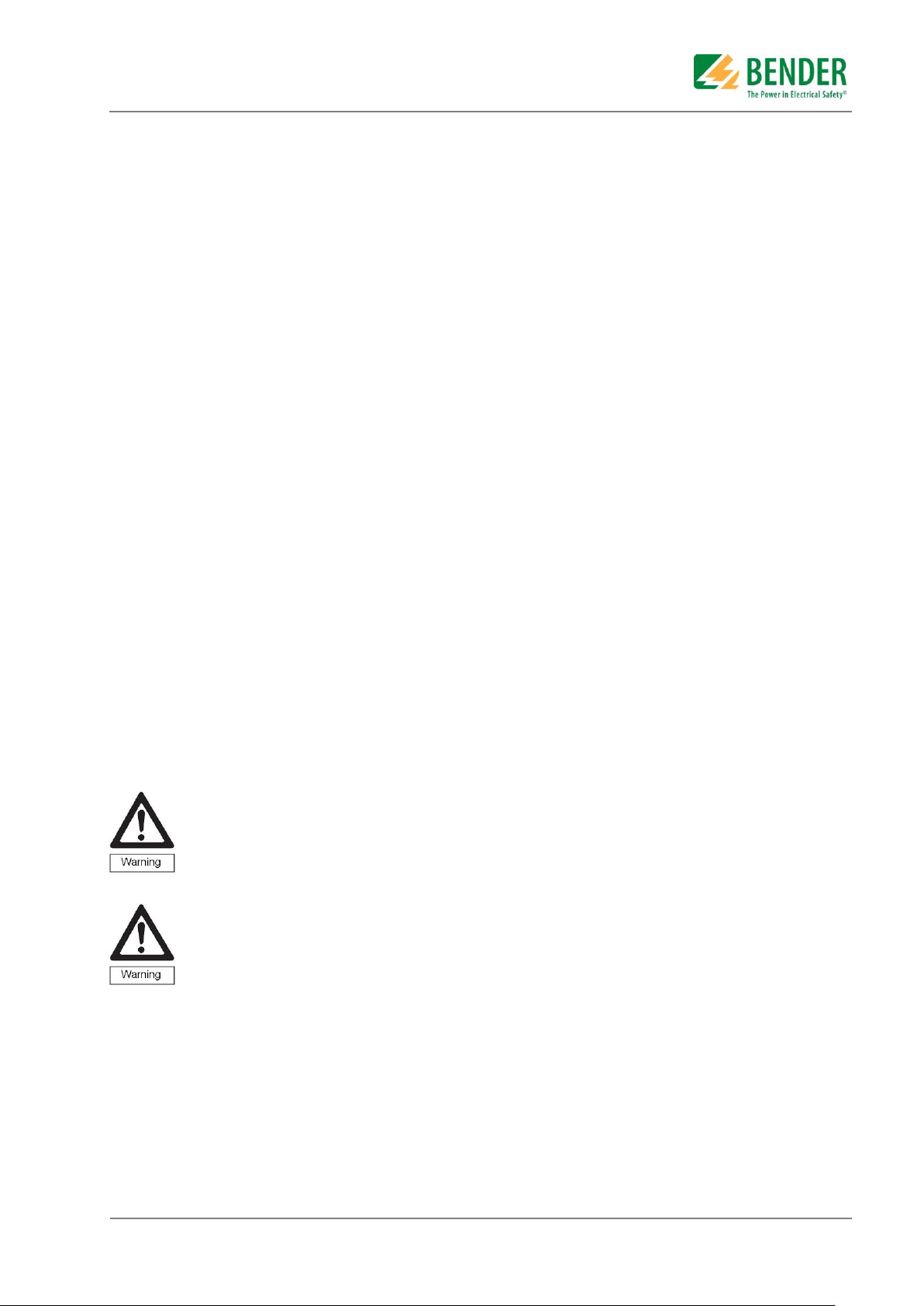
1.2. Explanations of symbols and notes
The following terms and symbols are used to denote hazards and instructions in Bender documentation:
This symbol indicates an immediate risk to life and limb.
Failure to observe the associated instructions and take appropriate precautions will result in
death, severe bodily injury or substantial damage to property.
This symbol indicates a potential risk to life and limb.
Failure to observe these warnings and take appropriate precautions may result in death, severe
bodily injury or substantial damage to property.
This symbol indicates a potentially dangerous situation.
Failure to observe the associated instructions and take appropriate precautions may result in
minor bodily injury or damage to property.
This symbol indicates important information about the correct use of the equipment purchased.
Failure to observe the associated instructions can result in equipment malfunctioning or cause
problems in the environment in which it is being used
This symbol indicates tips for using the equipment and particularly useful information. This type
of information will help you to optimise your use of the equipment.
Alle Rechte und Änderungen vorbehalten. Subject to change without notice. All rights reserved. © Bender GmbH & Co KG
UMA710-2-xx-ISO-xx, Manual.docx Issued: 11.Jan.2016 5
Page 6
2. Safety instructions
2.1. Intended use
Changeover devices are used everywhere there is dependence on high availability from the power supply.
The ATICS® transfer switching device is intended for the application described in the chapter "System
description". When the preferred supply fails, the ATICS® automatically switches to the second supply.
Areas of application:
Group 1 and 2 medical locations according to DIN VDE 0100-710 and IEC 60364-7-710
Hospital main distribution boards (DIN VDE 0100-710)
Locations open to the public (DIN VDE 0100-718)
Emergency power supplies
Heating, air conditioning, ventilation, cooling
EDP, computer centres
Fire extinguisher and sprinkler systems
Several versions of the ATICS® are available. They differ for example by changing over from the two or
four-pole systems or by the load current (see chapter "ATICS® tasks" on page 15). Please heed the limits
of the area of application indicated in the technical specifications. Use which deviates from or is beyond the
scope of these technical specifications is considered non-compliant.
In order to meet the requirements of applicable standards, customised parameter settings must be made
on the equipment in order to adapt it to local equipment and operating conditions.
Intended use includes following all the instructions in the operating manual and complying with the test
intervals.
2.2. Skilled persons
Only appropriately qualified personnel may work on Bender devices. Persons who are familiar with the
assembly, commissioning and operation of the equipment and have undergone appropriate training are
considered skilled persons. Such persons must have read this manual and understood all instructions
relating to safety.
2.3. Device-specific safety instruction
Failure to adjust the settings may result in malfunction.
The settings must be changed in order to adapt the ATICS® transfer switching device to the
existing equipment. When doing so, follow the instructions in chapter "5. Commissioning,
settings and testing“.
Functional safety according to IEC 61508 can only be guaranteed when used properly.
Please follow the instructions given in this operating manual and in the check list.
In particular note the information on the pages: 12, 13, 14, 20, 52 and 76 in the technical
operating manual TGH1443 of the ATICS® device.
Alle Rechte und Änderungen vorbehalten. Subject to change without notice. All rights reserved. © Bender GmbH & Co KG
UMA710-2-xx-ISO-xx, Manual.docx Issued: 11.Jan.2016 6
Page 7

2.4. General safety instructions
Bender devices are designed and built in accordance with the state of the art and accepted rules in respect
of technical safety. However, the use of such devices may introduce risks to the life and limb of the user or
third parties and/or result in damage to Bender devices or other property.
Only use Bender equipment:
– As intended
– In perfect working order
– In compliance with the accident prevention regulations and guidelines applicable at the
location of use
Eliminate all faults immediately which may endanger safety.
The device may not be opened.
Do not make any unauthorised changes and only use replacement parts and optional accessories
purchased from or recommended by the manufacturer of the equipment. Failure to observe this
requirement can result in fire, electric shock and injury.
Information plates must always be clearly legible. Replace damaged or illegible plates immediately.
Make sure that the dimension of the UPS (special safety power supply source), the generator set
and the whole wiring is adequate. Abide by the relevant, applicable national and international
standards. If there is an overload and short-circuit, this is the only way to guarantee the necessary
safety and to ensure that the safety devices respond selectively.
If the device is overloaded by overvoltage or a short-circuit current load, it must be checked and
replaced if necessary.
2.5. Delivery conditions, guarantee, warranty and liability
The conditions of sale and delivery set out by Bender GmbH shall apply.
Conditions of sale and delivery can be obtained from Bender GmbH in printed or electronic format.
Alle Rechte und Änderungen vorbehalten. Subject to change without notice. All rights reserved. © Bender GmbH & Co KG
UMA710-2-xx-ISO-xx, Manual.docx Issued: 11.Jan.2016 7
Page 8
3. System description
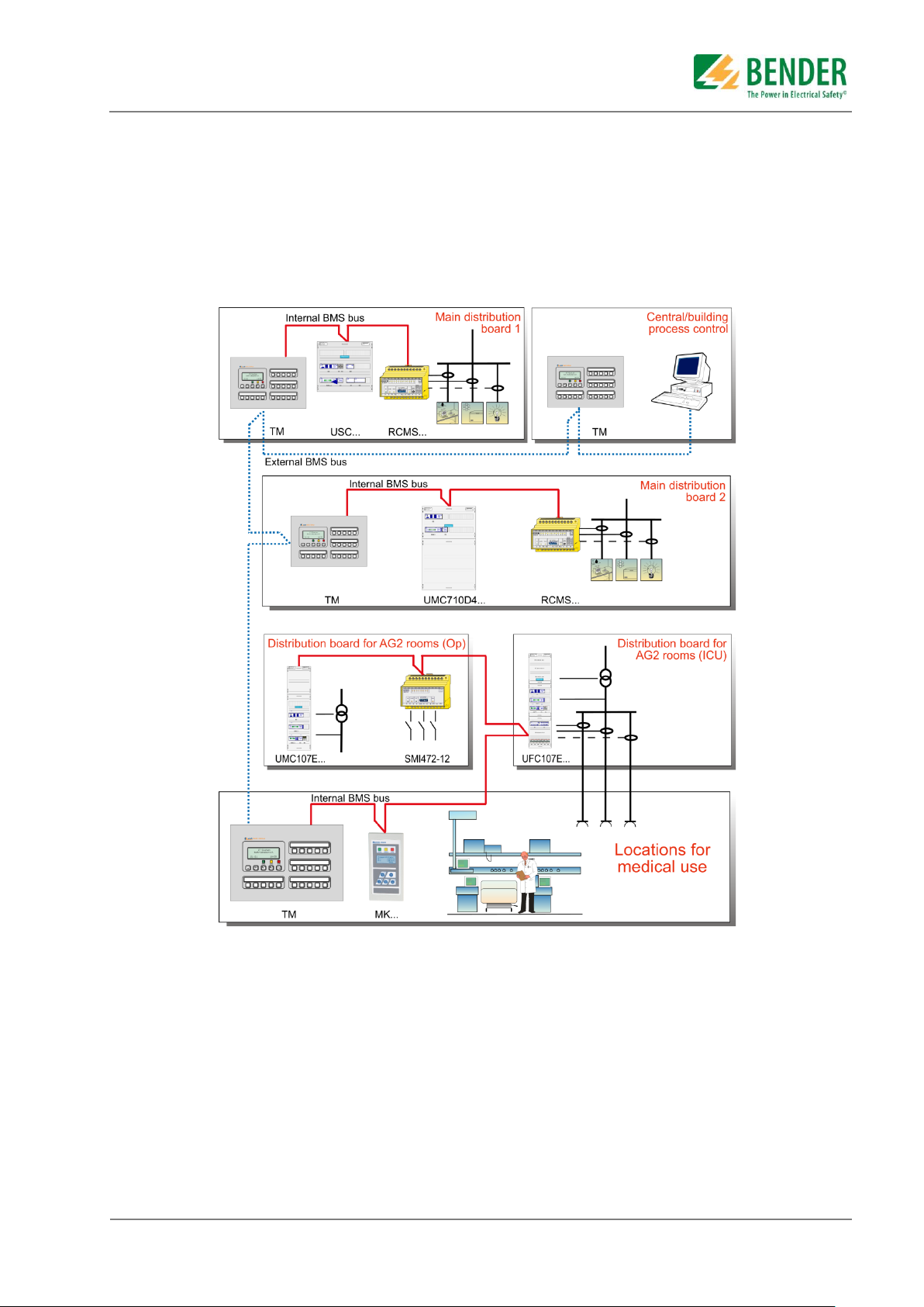
3.1. MEDICS®
The UMA710... change over and monitoring module is a part of the MEDICS® system. MEDICS® does not
refer to a single product, but rather an intelligent system for safe power supplies in medical locations.
Example of a section of a hospital with the MEDICS® system
Table to the example
MK... Alarm indicator and test combination
RCMS... Residual current monitoring system for TN-S systems
SMI472 Signal converter for third-party technical equipment (e. g. med. gases, UPS)
TM Alarm and control panel
UMA710-2... Change over and monitoring module ATICS® for IT-Systems
UMC107E.. Change over and monitoring module with contactors for IT-Systems
UMA710-2... Change over and monitoring module ATICS® for IT-Systems with EDS... insulation fault
location system.
UFC107E... Change over and monitoring module for IT systems with EDS... insulation fault location
system
UMC710D... Changeover and monitoring module for main distribution boards
USC710D... Control module for changeover modules (preferably in main distribution boards)
Alle Rechte und Änderungen vorbehalten. Subject to change without notice. All rights reserved. © Bender GmbH & Co KG
UMA710-2-xx-ISO-xx, Manual.docx Issued: 11.Jan.2016 8
Page 9
MEDICS® includes::
AC and 3(N) AC changeover and monitoring modules. Examples of modules in the MEDICS®
system include UMC..., USC..., UFC... and EDS.... insulation fault location systems.
Display and operating units such as alarm indicator and operator panels or alarm indicator and test
combinations.
Communication between these components takes place via the BMS bus (two-wire connection).
The connection of third-party technical equipment by means of protocol converters (gateways), via
digital inputs and relay outputs.
The real strength of MEDICS® is to be found in communication between all involved components and the
resulting information provided to the user. Readiness for operation is monitored constantly; and operating
states, irregularities, faults and equipment failures are displayed. From the user's point of view, this means
high operational reliability.
3.2. Example applications
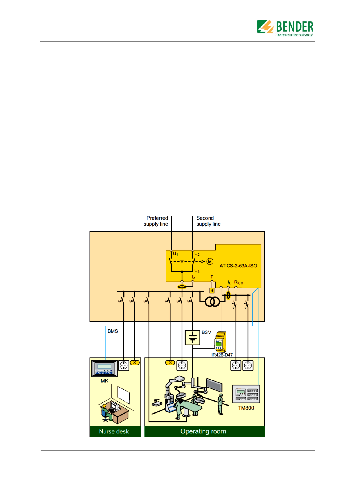
3.2.1. Example application operating theatre
UMA710 Module, Changeover between the preferred and redundant line while monitoring the
medical IT system with transformer load and temperature monitoring
IR426-D47: Monitoring the operating theatre light IT system (optional)
MK2430 / MK800 / TM800: Alarm for at least two points with independent power supplies for
functional safety
Alle Rechte und Änderungen vorbehalten. Subject to change without notice. All rights reserved. © Bender GmbH & Co KG
UMA710-2-xx-ISO-xx, Manual.docx Issued: 11.Jan.2016 9
Page 10
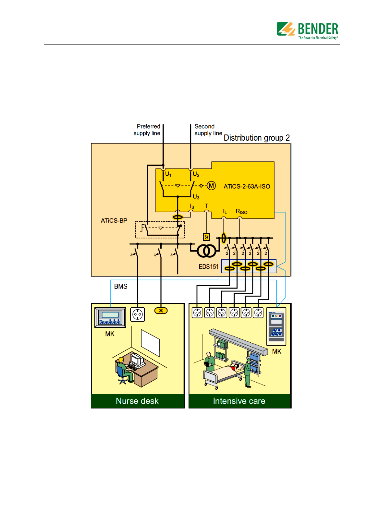
3.2.2. Example intensive care unit
UMA Module, Changeover between the preferred and redundant line while monitoring the
medical IT system with transformer load and temperature monitoring including a bypass switch
EDS151 Insulation fault locator for fast insulation fault location (recommended)
ATICS-BP: Bypass switch for uninterrupted test / maintenance (recommended)
MK2430 / MK800 / TM800: Alarm for at least two points with independent power supplies for
functional safety
Alle Rechte und Änderungen vorbehalten. Subject to change without notice. All rights reserved. © Bender GmbH & Co KG
UMA710-2-xx-ISO-xx, Manual.docx Issued: 11.Jan.2016 10
Page 11

3.3. Features of the UMA710…
The ATICS® transfer switching device has the following features:
Continuous monitoring of the internal electronic and the circuitry with automatic alarm
Preventive safety due to an automatic reminder of mandatory testing procedures
Maximum reliability of the switching
o Patented switching system with mechanical and electrical interlocking
o Short circuit proof contacts with the mechanic of a moulded case circuit breaker
o Insensitive to voltage fluctuation and vibration due to stable switch position and permanent
contact pressure
Easy to use and a good overview due to a clear menu structure and user interface
The right information at the right time with clear alarm text and a backlit graphic display as well as
via the BMS bus
Can manually be operated and can be locked for maintenance in position “0”
Automatic logging of events e.g. switching, testing, parameter changes
External functional test or replacement of the ATICS® via an optional bypass switch
The ATICS® switch is pluggable
Electronic and switching elements all in one enclosure respectively on a mounting rack
Chang over and IT-System monitoring in one unit
Optional bypass switch
Communication of components with one another via BMS bus
Communication with remote alarm indicator and test combinations and TM alarm indicator and
operator panels via BMS bus
Can be used in systems in accordance with IEC 60364-7-710:2002-11, sections 556.5.2.2, 556.7
and 556.8 and DIN VDE 0100-710 (VDE 0100 Part 710):2002-11, section 710.564.6 with a
changeover period = 15 s or = 0.5 s
Functional Safety according to IEC 61508 for use in special safety environment according to SIL2
Easy field wiring, completely prewired and type tested assembly
The UMA710 module is a configured unit and is only certified and tested in this assembly. Do
not make any changes to the components, their password-protected settings or the wiring
without consulting Bender first. In each case you should make the settings that are required for
adaptation to the application case in question and local conditions.
Alle Rechte und Änderungen vorbehalten. Subject to change without notice. All rights reserved. © Bender GmbH & Co KG
UMA710-2-xx-ISO-xx, Manual.docx Issued: 11.Jan.2016 11
Page 12

3.4. The automatic changeover module UMA710…
3.4.1. The transfer switching device
If the preferred supply fails, the ATICS® ensures the power supply is changed over safely. The switch
contacts are offset on a rotating shaft. This design prevents simultaneous switching of line 1 and line 2. The
switch has three positions:
1 Line 1 switched on
0 Both lines switched off
2 Line 2 switched on
Either line 1 or line 2 can be set as the preferred line
In the normal condition (fault-free operation) the preferred supply is connected. The ATICS® will
switch to the redundant line if:
– the preferred line fails
– the "TEST" button is pressed
– a digital input is configured to "TEST" and this input is enabled
– the setting "Preferred supply" is reconfigured to the other line
The ATICS® switches from the redundant line back to the preferred line if
– the voltage on the preferred line is restored
- the return transfer delay time T(2->1) has expired and no switching back interlocking function is
enabled
- or immediately after pressing the "RESET" button or when the redundant line fails (even when the
switching-back interlocking function is enabled)
– the setting "Preferred supply" is reconfigured to the other line
– the digital input is configured to "TEST" and this input is reset
– a transfer switching device test is enabled and the test time has expired
With the optional ATICS-ES energy storage device only: The ATICS® changes to switch position
"0" and stays there if the following conditions are simultaneously met:
– Line1 and Line 2 have failed
– Automatic mode is set
– No short-circuit is present downstream of the transfer switching device
– The setting "Load disconnection" is set to "on" and the external ATICS-ES energy storage device
is connected
Malfunction if delay times are not adjusted
The response delay T(on), the return transfer delay time T(2->1), the delay on release T(off)
and the dead time T(0) of the ATICS® are adjustable and must be adjusted to the
requirements of the specific case, the short-circuit-calculation and the requirements of DIN
VDE 0100-710 (VDE 0100 Part 710) Section 710.537.6 automatic changeover devices (see
also chapter "Commissioning, settings and testing").
The factory settings guarantee a changeover period of t = 0.5 seconds and switching back within 10
seconds when voltage is restored on the preferred supply. Therefore, the ATICS® can be used in IT
systems with a requirement for a changeover period t ≤ 0.5 s (IT systems with operating theatre lights,
endoscopic field illumination in operating theatres or other essential sources of light, etc.).
When there is a short circuit downstream of the transfer switching device, the transfer switching device
must not continually change back and forth between the two lines. This can occur when the short-circuit
current is small and the transfer switching device switches faster than the short circuit breaker trips. The
ATICS® monitors the load current downstream of the transfer switching device in order to detect a possible
short circuit. If the preferred line fails and a short-circuit current is detected at the same time, the ATICS®
does not change over immediately but only once the circuit breaker has tripped.
If the ATICS® detects a supply failure or a fault, an alarm appears on the LCD, the "ALARM" LED lights
up, the alarm relay trips (if set) and this alarm is forwarded to other Bender devices (such as an alarm
indicator and test combination) via the BMS bus.
Alle Rechte und Änderungen vorbehalten. Subject to change without notice. All rights reserved. © Bender GmbH & Co KG
UMA710-2-xx-ISO-xx, Manual.docx Issued: 11.Jan.2016 12
Page 13

Typical time diagrams can be found in the following chapters of the ATICS® switch user manual
TGH1443 issued by Bender GmbH.
TGH1443, chapter 3.5.1.1
Time diagram: Changeover between the preferred and redundant line
Example: Line 1 is set as the preferred line.
TGH1443, chapter 3.5.1.2
Time diagram: Staggered switching after total power failure
The external ATICS-ES energy storage device (optional, see "Ordering information") is required for the
staggered switching. If there is no voltage on either of the power supplies, the ATICS® switches to position
"0". When the power is restored, the ATICS® switches on the supply again with the set delay time T(start).
Example: Line 1 is set as the preferred line.
TGH1443, chapter 3.5.1.3
Time diagram: Changeover to generator mode
Alle Rechte und Änderungen vorbehalten. Subject to change without notice. All rights reserved. © Bender GmbH & Co KG
UMA710-2-xx-ISO-xx, Manual.docx Issued: 11.Jan.2016 13
Page 14
3.4.2. Insulation monitoring of the IT-System
Insulation monitoring
The integrated insulation monitoring device measures the insulation resistance on AC IT systems, which
may also contain DC voltage components. Adaptation to the system leakage capacitances occurs
automatically. The measuring time increases as the system leakage capacitances increase.
Load current measurement
The load current on the IT system is measured using an STW2 measuring current transformer.
Temperature monitoring
The temperature in the transformer winding is measured via PTC thermistors.
Evaluation
If any of the measured values does not fall within the limits, an alarm is triggered. A message appears
on the LCD, the "ALARM" LED lights up, the alarm relay trips (if set) and this alarm is forwarded to other
Bender devices (such as an alarm indicator and test combination) via the BMS bus.
Locating current injector
When an insulation fault is detected on an IT system, the integrated locating current injector generates
a defined locating current signal to locate the insulation fault. The locating current is limited to
1 mA. This feature can be switched on or off (see chapter "7.4.4.4 Settings menu 4: IT system").
The locating current flowing between the IT system and earth can cause controller faults in
sensitive parts of the system, such as the PLC or relay. It must therefore be ensured that the
locating current is compatible with the monitoring
3.4.3. Monitoring the device functions
The control circuits are designed in such a way that, even though it is almost certain that a particular fault
will occur, it cannot cause the power supply at the output of the automatic transfer switching device to fail.
The ATICS® also continuously monitors:
The switch position of the switch and coils 1 and 2 of the switch
Power supplies 1 and 2, which supply the electronics from the systems concerned
Internal microcontrollers and memory modules
Important connecting wires, such as:
– Measuring current transformer connection
– Temperature sensor connection
– Power supply and PE connection
For alarm and test combinations, and alarm indicator and operator panels, device failure
monitoring can also be programmed via the BMS bus (necessary for functional safety).
On systems with generator: total power failure possible
If the preferred line fails, the ATICS® starts the generator which is connected to the redundant
line. If the generator does not start, the line downstream of the transfer switching device will be
dead. When the generator is switched off, the ATICS® cannot check the redundant line.
Therefore, regularly test the generator and the changeover function to make sure they are
working properly (see checklist in the Appendix to this manual).
Alle Rechte und Änderungen vorbehalten. Subject to change without notice. All rights reserved. © Bender GmbH & Co KG
UMA710-2-xx-ISO-xx, Manual.docx Issued: 11.Jan.2016 14
Page 15

3.4.4. Power supply
The coils of the switching device are each supplied from the line which is not currently switched on. This
ensures that it is possible to switch to the redundant line if the preferred line fails, for example. The power
supply of the electronic system is of redundant supply from the lines 1 and 2. This ensures constant supply
to the electronic system even when one line fails. If both lines fail, the changeover switch remains in the
last switch position. Optionally, the external ATICS-ES energy storage device can be connected to supply
the two coils and the electronic system. It is then possible to change over to switch position "0". If several
ATICS® are installed on one system, they can be switched to the preferred line one-by-one starting from
switch position "0" on voltage recovery. This prevents peak loads occurring which would otherwise occur if
the lines of several transfer switching devices were switched on simultaneously.
3.4.5. Manual mode
In manual mode, changeover can be achieved using an Allen key. The changing over to switch position "0"
can be locked with a padlock.
3.4.6. Bypass mode (optional)
By using the optional bypass switch (S1) the changeover and monitoring module can be set into the bypass
mode. In this case the switch will bypass the ATICS® (N1) unit. The ATICS® switch can then be tested or
replaced without power interruption downstream to the changeover and monitoring module.
Only skilled persons may work or operate the changeover and monitoring module. Skilled
means, persons who are familiar with the assembly, commissioning and operation of the
equipment and have undergone appropriate training. Such persons must have read this manual
and understood all instructions relating to safety.
Please refer to the chapter “operation of the bypass mode”.
Alle Rechte und Änderungen vorbehalten. Subject to change without notice. All rights reserved. © Bender GmbH & Co KG
UMA710-2-xx-ISO-xx, Manual.docx Issued: 11.Jan.2016 15
Page 16

Description
Identification
Function
ATICS-2-xx-ISO
N1
Automatic changeover and monitoring
unit, 63A or 80A nominal current
including IT-system monitoring
CP-D24/0.24
(or AN410 )
T1
Auxiliary power supply for remote alarm
indicator MK-series
BV384213 (STW2)
T4
Measuring current transformer for the
actual load current on transformer
secondary
STW3
T3
Measuring current transformer for the
total load current and to identify a short
circuit condition
ES710…
ES710…
IT-System transformer, 3150VA upto
8000VA,
According to DIN VDE 0100-710
Fuse
F1, F2,
Short circuit protection
MK2430-xx
MK2430-xx
for remote alarm indicator MK-series
Bypass switch
(optional)
S1
To bypass the load contacts of the
ATICS® switch, with auxiliary contacts
E219-2CD48
(optional with bypass switch)
H1
indicator, red + green to indicate the
bypass mode
4. System components
In the appendix of this manual you will find the data sheets, technical manuals and further detailed
information on all system components.
The changeover and monitoring modules are designed to be mounted on DIN rails but can also be
mounted on mounting plates.
Multiple DIN rails are mounted on mounting racks of at least one vertical section of 250mm in width. Other
mounting arrangements with multiple vertical sections are also possible.
Depending on the number of sections the DIN rails may also differ. E.g. a wall mounted enclosure with 6
DIN rails in one vertical section or a switchgear cabinet with 10 or 12 DIN rails per vertical and multiple
sections in a free standing cabinet.
The following mounting racks will show some typical arrangements only.
The optional bypass switch is also being showed in these examples.
Alle Rechte und Änderungen vorbehalten. Subject to change without notice. All rights reserved. © Bender GmbH & Co KG
UMA710-2-xx-ISO-xx, Manual.docx Issued: 11.Jan.2016 16
Page 17

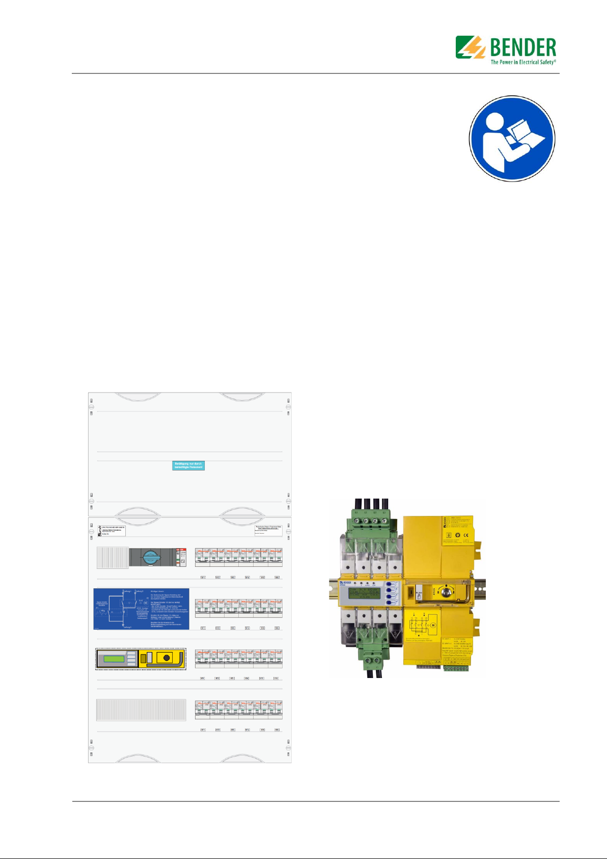
Legend
1. Cover of the terminal area
2. Cover with all mounted components
3. Label with technical data
4. Type label
5. Aux. supply, T1
6. indicator, H1 (optional), for bypass-circuitry
7. bypass switch S1 (optional)
8. label (optional), for bypass-circuitry with
important operating instructions
9. automatic changeover and monitoring unit
ATICS®, N1
10.
This is only an example of a typical mounting rack
arrangement only. Please refer to the attached
individual, job or project related documentation like
wiring diagram and elevation drawing.
4.1. Front view of atypical UMA710-2-xx-ISO-BP
Example: front view UMA710-2-xx-ISO-BP on a single section mounting rack by ABB/Striebel & John.
Alle Rechte und Änderungen vorbehalten. Subject to change without notice. All rights reserved. © Bender GmbH & Co KG
UMA710-2-xx-ISO-xx, Manual.docx Issued: 11.Jan.2016 17
Page 18

Legend
1. terminals, in-coming
2. terminals, IT-System transformer
3. fuses, F1, F2 (see also chapter 7.3)
4. terminals, interfacing
5. measuring current transformer T3 (for load
current monitoring)
6. aux. supply T1, DC 24V
7. bypass switch S1 (optional)
8. indicator H1 (optional), for bypass circuitry
9. current transformer T4 (for short circuit
detection)
10. automatic changeover and monitoring unit
ATICS®, N1
This is only an example of a typical mounting rack
arrangement only. Please refer to the attached
individual, job or project related documentation like
wiring diagram and elevation drawing.
4.2. Typical mounting arrangement UMA710-2-xx-ISO-BP
Example: UMA710-2-xx-ISO-BP on a single section mounting rack by ABB/Striebel & John.
Alle Rechte und Änderungen vorbehalten. Subject to change without notice. All rights reserved. © Bender GmbH & Co KG
UMA710-2-xx-ISO-xx, Manual.docx Issued: 11.Jan.2016 18
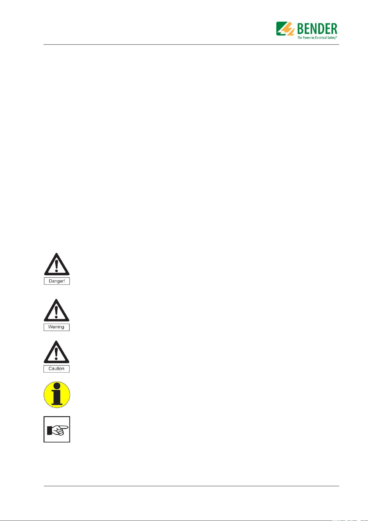
Page 19

1. LCD Display, indication of status, and alarm
messages and user menu
2. Status and alarm-LEDs
3. Push buttons/controls
4. green terminal plug, connection of line 1 and 2
5. inspection window for the switch position
6. manual operation of the ATICS® switch
showing also the switch position
7. Allen key wrench for manual operation
8. transparent cover for the changeover switch
(when opened in manual mode) lead-sealable
9. wiring schematic for line 1, 2 and 3
10. three coded connector plugs
11. latch for a patch lock to lock-up in position 0
12. green terminal plug, connection of line 3
4.3. Automatic changeover and monitoring unit ATICS®
For mounting and connection of the changeover and monitoring unit ATICS® read chapter 4 of
the technical user manual TGH1443
Alle Rechte und Änderungen vorbehalten. Subject to change without notice. All rights reserved. © Bender GmbH & Co KG
UMA710-2-xx-ISO-xx, Manual.docx Issued: 11.Jan.2016 19
Page 20

Legend
1. In-coming terminals
2. IT-System transformer terminals
3. F1, F2: fuses (see also chapter 7.3)
4. Interfacing terminals
This is only an example of a typical mounting rack arrangement only. Please refer to the
attached individual, job or project related documentation like wiring diagram and elevation
drawing.
4.4. Typical terminal setup
Alle Rechte und Änderungen vorbehalten. Subject to change without notice. All rights reserved. © Bender GmbH & Co KG
UMA710-2-xx-ISO-xx, Manual.docx Issued: 11.Jan.2016 20
Page 21

5. Installation of UMA710-2-xx-ISO-xx-…
5.1. Safety Advice
The safe use of this electrical equipment implies that it has been wired-up and commissioned by electrical
skilled personnel.
Only skilled persons may work on this module. Skilled means, persons who are familiar with
the assembly, commissioning and operation of the equipment and have undergone appropriate
training. Such persons must have read this manual and understood all instructions relating to
safety.
• The latest standards and regulations have to be followed.
• The national safety and accident prevention regulations have to be followed.
• The power has to be turned off before working on this electrical equipment.
• Precautions have to be made that the equipment can not be turned back on by accident.
• The connection/wiring is only allowed in compliance to the wiring diagram and its comments.
If the comments and wiring diagrams are not being followed, the wiring been changed or not recommended
accessory is being used, injury, fire, electrical shock and other damage can occur.
The unique and individual wiring diagram and elevation drawings of this module as well as the
data sheets of the installed components, are also part of this operation manual and must be
carefully read as well.
5.1.1. Short circuit protection
Please observe the requirements of IEC 60364-7-710:2002-11 and DIN VDE 0100-710 (VDE 0100 Part
710) when selecting fuses for the supply cables and outgoing circuits of the changeover modules:
Section: 710.512.1.6.2 (VDE), sections 710.5.3.1, 710.512.1.6 (IEC), Transformers for the IT
system: Where transformers, their primary supply conductor and secondary outgoing line are
concerned, overcurrent protective devices are only permitted for short-circuit protection. The
transformer supply cable from the changeover module and the transformer outgoing cable to the
next distribution board section should be laid so that they are short-circuit proof and earth fault
proof. Recommended cable/wire: Halogen-free, flexible single core, double insulated rubber wire
type NSHXAFö 1.8/3kV.
Section: 710.53.2 (VDE), section 710.413.1 (IEC), Protection of the cable system in Group 2
locations: The choice of protective devices must ensure that when the anticipated short-circuit
current occur, the protective device upstream of a fault will selectively trip the protective devices
that are further upstream.
Section 710.537.6.2. (VDE), section 710.413.1.1 (IEC), Connecting several load groups
downstream of a changeover module must not lead to all the load groups failing in the event of a
fault. As a result, the choice of fuses F should ensure both short-circuit protection for the
transformer and selectivity for the overcurrent devices connected downstream in the IT systems
Alle Rechte und Änderungen vorbehalten. Subject to change without notice. All rights reserved. © Bender GmbH & Co KG
UMA710-2-xx-ISO-xx, Manual.docx Issued: 11.Jan.2016 21
Page 22

When selecting fuses, please observe both the maximum permissible values laid down by the guidelines
that apply to the location of use and national and international standards, in order to ensure that the
contactor contacts cannot weld. The considerations presented below are based on the standard DIN VDE
0100-710 (VDE 0100 Part 710):2002-11, section 710.537.6.
Selecting the fuse with one consumer only.
The circuitry has only one consumer (IT-System
transformer)
The minimum rating of the fuse has to be given by
the transformer manufacturer
The nominal current of the ATICS® unit must be
higher or at least equal to the nominal current of
the IT-system transformer.
The maximum possible fuse F1 and F2 up-stream
is given by the technical data of the ATICS® unit
Selecting the fuse with more than one consumer.
This circuitry branches off in multiple consumers.
This implies that there is a fuse for each consumer
behind the ATICS® unit.
Nevertheless the maximum possible fuse F1 and
F2 up-stream is given by the technical data of the
ATICS® unit.
The fuse F1 and F2 must be selected that there is
a discrimination to the fuses F3, F4 and F5.
Therefore the fuse F3 must be at least two ranges
lower than the ATICS® nominal current.
The total current of the changeover arrangement is
the total expected load current of all connected
consumers.
Alle Rechte und Änderungen vorbehalten. Subject to change without notice. All rights reserved. © Bender GmbH & Co KG
UMA710-2-xx-ISO-xx, Manual.docx Issued: 11.Jan.2016 22
Page 23

Function
Terminal description
Preferred supply line, line 1 *)
Phase, L
Neutral, N
Earth, PE
Second supply line, line 2 *)
Phase, L
Neutral, N
Earth, PE
IT-System transformer *)
Primary, L
Primary, N
Secondary, L1
Secondary, L2
Shield, PA/S
Temperature monitoring
Remote alarm indicator, control panel
(MK2430-xx, MK800-xx)
Internal BMS-Bus, A, B
Internal BMS-Bus, A , B
The terminals can also be used to terminate the bus
with a 120ohm resistor.
Shield S = PE (The shield shall be earthed on one
side of the cable only.)
Aux. Supply voltage, +24V, 0V
Alarm contact
Volt-free changeover contact, (programmable)
„Bypass ON“ contact
Volt-free N.O. contact, (optional, for bypass only)
Alarm and control panel
(TM, FM, TCP)
Aux. supply voltage AC 230V,
L1 , L2, PE
IT-System branch circuits
Terminal block L1/L2/PE
5.2. Changeover module
5.2.1. Typical connection
Connect the changeover module to the typical terminals:
*) Select the cross section according to the applicable national and international standards.
(e.g. DIN VDE 0100 part 430)
Please refer to the attached individual, job or project related documentation like wiring diagram
and elevation drawing
5.2.2. Wiring diagram UMA710-2-xx-ISO, …-BP
The complete wiring diagram can be found in the appendix of this manual.
Please refer to the attached individual, job or project related documentation like wiring diagram
and elevation drawing
Alle Rechte und Änderungen vorbehalten. Subject to change without notice. All rights reserved. © Bender GmbH & Co KG
UMA710-2-xx-ISO-xx, Manual.docx Issued: 11.Jan.2016 23
Page 24

5.3. Notes for connecting the module
On any of the below please refer to the attached individual, job or project related
documentation like wiring diagram and elevation drawing.
5.3.1. Transformer
The power supply of Group 2 location is supplied via an isolating transformer. For protection
against indirect contact, one of the following measures is to be used for the transformer:
Protective insulation according to DIN VDE 0100-410 (VDE 0100 Part 410):2007-06, 413.2 (Use of
a protection class II transformer)
Protection by non-conductive location according to DIN VDE 0100-410 (VDE 0100 Part 410):2007-
06, section 413.3
Protection by a local, earth-free equipotential bonding according to DIN VDE 0100-410 (VDE 0100
Part 410):2007-06, section 413.4
Protection by special installation. For this measure, please note the following:
- The protection class I transformer must be installed isolated and must not be connected to
the PE conductor. In Bender's ES710 range of transformers, the fixing angles are isolated
from the transformer core.
- A warning label is to be affixed to the transformer and its cover as follows:
Warning! Accessible parts of the transformer may be live. You must always verify
that there is no voltage present before touching parts of it.
- The transformer is to be installed behind a cover, which can only be opened using a tool or
a special key. It must only be accessed by skilled persons.
- The shield winding can be connected to the PE conductor. It must be ensured that the
connecting wire is installed so that it is short-circuit proof and earth-fault proof.
5.3.2. Temperature sensor
Bender IT system transformers are equipped with the temperature sensors required according to their
insulation class. These temperature sensors (maximum of 6 sensors connected in series) are connected to
terminals Z1 and Z2.
5.3.3. Out-going branch circuit breakers (optional)
As an option the UMA module can be equipped with 2-pole branch circuit breakers to provide the ITSystem supply. The load circuits can be connected to terminal block. Please refer to the attached
individual, job or project related documentation like wiring diagram and elevation drawing.
Alle Rechte und Änderungen vorbehalten. Subject to change without notice. All rights reserved. © Bender GmbH & Co KG
UMA710-2-xx-ISO-xx, Manual.docx Issued: 11.Jan.2016 24
Page 25

5.3.4. Remote alarm indicator
Ex works, the following A+B terminals are provided for the connection of BMS bus devices:
Remote alarm indicator, control panels and other Bender-BMS-bus devices can be connected to these
terminals.
1. A BMS device or an existing BMS bus with several devices is connected to terminals: The last
device at the other end of the bus must be terminated with 120ohm. Terminals A and B remain
terminated.
2. An existing BMS bus that has already been terminated on both ends, is disconnected; one open
branch is connected to terminals A+B, while the other one is connected to the other terminals A+B:
The 120 Ω resistor, provided ex works, must be removed and the open bus branches must be
connected to the specified terminals.
Please read the information on cable routing in the "BMS bus" instruction leaflet as well as the
individual, job or project related BMS bus wiring schematic if applicable.
The power supply unit T1 (DC 24V, 420mA) can supply power to a maximum of three MK2430 alarm
indicator and test combinations via the terminals +24V and 0V. In this respect, please refer to the
documentation for the relevant devices. The power supply unit T1 is not suitable for supplying power to
TM... operator panels. Alarm and control panels /e.g. TM, FM, TCP series) can be supplied via the 230V
terminals (where applicable).
5.3.5. Building management and SCADA system
If messages from the UMA changeover and monitoring module are to be transmitted to a SCADA system,
you have the following options:
Protocol converter (Gateways)
OPC-Server
Common alarm via the relay outputs of the ATICS® unit
Conversion between BMS bus and digital inputs and outputs by means of alarm indicator and
operator panels (e.g. TM, FM, TCP) or signal converters (e.g.SMO480-12, SMO482-12, SMI 472-
12).
5.3.6. Bypass-switch (optional)
By using the optional bypass switch (S1) the changeover and monitoring module can be set into the bypass
mode. In this case the switch will bypass the ATICS® (N1) unit. The ATICS® switch can then be tested or
replaced without power interruption downstream to the changeover and monitoring module.
Only skilled persons may work or operate the changeover and monitoring module. Skilled
means, persons who are familiar with the assembly, commissioning and operation of the
equipment and have undergone appropriate training. Such persons must have read this manual
and understood all instructions relating to safety.
Please refer to the chapter “operation of the bypass mode” of this manual.
Alle Rechte und Änderungen vorbehalten. Subject to change without notice. All rights reserved. © Bender GmbH & Co KG
UMA710-2-xx-ISO-xx, Manual.docx Issued: 11.Jan.2016 25
Page 26

6. Commissioning, settings and testing
6.1. Design and installation notes
Note for the design:
During installation and connection, abide by the relevant standards and regulations and follow the
operating manuals for the device.
Provide for MK… alarm indicator and test combinations or TM… alarm indicator and operator
panels at least two places. These show messages from the ATICS® transfer switching device and
monitor one another for failure.
Example of locations for the MK… or TM… in a hospital:
o Medical locations
o Continuously manned area (e.g. nurse service area)
o Technical area
Provide a fail-safe power supply for the MK… or TM… or TCP
The TM… and MK… for the medical and technical area must be supplied with power from different
lines and sources. Example:
The MK… or TM… in the medical field is supplied from line 3 of the transfer switching device.
The MK… in the technical area is supplied from a fail-safe battery-backed line..
Notes on parameter settings:
MK… resp. TM…or TCP must display at least the following faults detected by the ATICS®:
Failure line 1, failure line 2
Device error, device failure ATICS®
Failure of the other MK… or TM… or TCP
Insulation fault, overload, over temperature of the IT-System
EDS channels with circuit and/or room name (where applicable)
Device error with complete text or error code
An overview of the ATICS® messages on the BMS bus (channel use) can be found in the technical user
manual TGH1443.
6.2. Setting and testing according to the checklist
The settings made at the factory take into account a total changeover period t ≤ 0.5 s and switching back to
the preferred supply within 10 seconds on voltage recovery.
Typical time diagrams can be found in the following chapters of the ATICS® switch user manual TGH1443
issued by Bender GmbH.
The response delay T(on), the dead time T(0), the delay on release T(off) and the return transfer delay time
T(2->1) of the ATICS® are adjustable and must be adjusted to the requirements of the specific case, the
short-circuit calculation and the requirements of DIN VDE 0100-710 (VDE 0100 Part 710) Section
710.537.6 (automatic changeover devices):
The total off-time (from the point at which the fault occurs until the arc in the overcurrent protective
device is cleared) must be less than the minimum delay for the changeover of the automatic
transfer switching device. Setting: Response delay T(on)
If several transfer switching devices are connected in series in a power supply system, it is
recommended that they be time-graded. Setting: Response delay T(on), return transfer delay time
T(2->1) and delay on release T(off).
As part of the response delay (to be custom-set), you must, at the very least, take into account the
periods of time when the circuit experiences short interruptions, and the response times of the
short-circuit protection equipment upstream or downstream. Regardless of this, a switchover pause
corresponding to the installation location should be taken into account, in order to avoid switching
overvoltages. Setting: Response delay T(on), dead time T(0) and return transfer delay time T(2>1).
Alle Rechte und Änderungen vorbehalten. Subject to change without notice. All rights reserved. © Bender GmbH & Co KG
UMA710-2-xx-ISO-xx, Manual.docx Issued: 11.Jan.2016 26
Page 27

The factory settings and system-specific settings of the ATICS® transfer switching device are
documented on the checklist. Please carry out all the work outlined in the list and log each test
step. The checklist can be found in the attached documentation. Keep the checklist with this
manual in the vicinity of the device.
6.3. Avoiding errors
Risk of missing or false messages on the display on MK… , TM… or FTC…
MK… alarm indicator and test combinations, TM… alarm indicator and operator panels or
FTC… protocol converters or BMS Ethernet gateways COM460IP, which, together with an
ATICS®, are connected to a BMS bus must be loaded with the latest operating software (e.g.
MK800/TM800 V 4.0 or higher, MK2430 V3.0 or higher). Older MK…, TM… or FTC… cannot
interpret the alarms of the ATICS®. They must either be updated or replaced.
The TMK-SET configuration software must also be the latest version.
Communication via the BMS bus can only be guaranteed when there is only one terminating
resistor at the beginning and the end of the BMS bus. Additional terminating resistors can lead
to malfunctions and therefore must not be used.
Please also note the information in the "BMS bus" instruction leaflet.
Alle Rechte und Änderungen vorbehalten. Subject to change without notice. All rights reserved. © Bender GmbH & Co KG
UMA710-2-xx-ISO-xx, Manual.docx Issued: 11.Jan.2016 27
Page 28

Unit
Parameter
Address setting
ATICS® for area A
Bus- Address
3
first MK…
(central monitoring)
Address
1
Test- Address
3, 6
Alarm- Address
2*, 3, 4**, 5, 6
second MK…
for area A
Address
2
Test- Address
3
Alarm- Address
1*, 3, 4**
EDS151 (optional)
Bus- Address
4
ATICS® for area B
Bus- Address
6
first MK…
for area B
Address
5
Test- Address
6
Alarm-Address
6
6.4. Example on how to set the addresses
Please also note the information in the "BMS bus" instruction leaflet.
Two ATICS® units and multiple remote alarm indicators and fault location:
* These alarm addresses are required to monitor each other.
** Each EDS channel shall be programmed individually to identify the branch circuit and the room in which
the load is being supplied.
Alle Rechte und Änderungen vorbehalten. Subject to change without notice. All rights reserved. © Bender GmbH & Co KG
UMA710-2-xx-ISO-xx, Manual.docx Issued: 11.Jan.2016 28
Page 29

6.5. Operation of the ATICS® unit
A brief commissioning instruction for the skilled personal is enclosed with the documentation.
Please refer to the document TKA1443. For detailed instruction of the changeover and
monitoring unit ATICS® read the technical user manual TGH1443.
6.6. Use of the bypass circuitry (optional)
By using the optional bypass switch (S1) the changeover and monitoring module can be set into the bypass
mode. In this case the switch will bypass the ATICS® (N1) unit. The ATICS® switch can then be tested or
replaced without power interruption downstream to the changeover and monitoring module.
Next to the bypass switch S1 is a green and red indicator H1 as well as the auxiliary power supply T1.
The green indicator is showing that the ATICS® unit is in position “I”. Only if the green indicator is ON the
bypass circuitry can be operated. In a fault free condition line 1 is in use and voltage is applied.
The bypass switch S1 must be operated only if:
- The ATICS® switch N1 is on position “I”
- The green indicator H1 is ON.
- If the red LED is ON or both are OFF there is a risk of short circuiting the supply.
The bypass switch must not be operated if the green indicator is OFF !
A failure to observe this may result in a short circuit when switching S1 to position “I+II” and
may result in the loss of power to the connected loads.
Important instruction:
If a power failure of line 1 occurs while the switch S1 is set to bypass mode in position “II” the
switch must not be operated again! In this case the ATICS® unit must be manually switched to
position “0” using the Allen key wrench.
Before the clear cover of the ATICS® unit is being firmly closed the bypass switch S1 has to be set
to position “I” again. If this instruction is not being followed the ATICS® will automatically
changeover to line 2 as soon as the cover is being firmly closed. Closing the clear cover will
activate the automatic mode of the ATICS® unit.
After each and every switching operation the normal operating condition has to be verified and logged in a
protocol.
Only skilled persons may work or operate the changeover and monitoring module. Skilled
means, persons who are familiar with the assembly, commissioning and operation of the
equipment and have undergone appropriate training. Such persons must have read this manual
and understood all instructions relating to safety.
Turn the bypass switch continuously from position “I” via “I+II” to position “II” to bypass the
ATICS® unit. Turn the bypass switch continuously from position “II” via “I+II” to position “I” to
run the ATICS® unit again in the none-bypass/normal mode.
The time in which the bypass is active in position “II” must be minimized.
Alle Rechte und Änderungen vorbehalten. Subject to change without notice. All rights reserved. © Bender GmbH & Co KG
UMA710-2-xx-ISO-xx, Manual.docx Issued: 11.Jan.2016 29
Page 30

Before operating the bypass circuitry note the instruction on the blue label on the cover: (optional)
Alle Rechte und Änderungen vorbehalten. Subject to change without notice. All rights reserved. © Bender GmbH & Co KG
UMA710-2-xx-ISO-xx, Manual.docx Issued: 11.Jan.2016 30
Page 31

Fault/message
Description
Action
Failure Line xx
(xx stands for: 1, 2,
AV, SV, UPS, BSV),
Under voltage or
overvoltage
Voltage is no longer available on
line 1 or line 2
(Channel 1 = Line 1,
Channel 2 = Line 2)
- Measure voltage on line xx
- Check cause
- Eliminate fault on the system
- Check the setting for voltage
and hysteresis
Failure Line 2
Generator delivers no voltage
within the set time
- Measure voltage on line xx
- Check cause
- Eliminate fault on the system
- Check the setting for voltage
and hysteresis
Insulation fault
IT-System insulation/earth fault
- Look for insulation fault
- Eliminate fault on the system
Overload
Current consumption too high
- Check setting for transformer
load current
- Switch off any loads which are
not urgently needed
Over temperature
Temperature on the IT system
transformer is too high
Switch off any loads which are
not urgently needed
CT connection
Measuring current transformer
STW2 (T4), isolating transformer
load, channel 10
- Check connecting wire of
measuring current transformer
CT short-circuit
Measuring current transformer
STW2 (T4), isolating transformer
load, channel 10
- Check connecting wire of
measuring current transformer
Mains power
connection
Connection to the IT system
interrupted or voltage in the
system being monitored below
150 V
- Check connection of ports
L1/IT, L2/IT to the IT system
- Check voltage in the IT system
Earth connection
Connection to PE interrupted
Check that the E and KE are
connected to the protective earth
conductor by two separate lines
on.
Device error +
Error code
For details about actions to be taken refer to table section "Error
code/service code". The message is on channel 6 of the BMS bus..
Short-circuit
distribution board
Short-circuit detected
- Eliminate short-circuit
Failure distribution board
No voltage on line 3, contact of
the changeover switch defective
Replace the ATICS®
Overcurrent I3
Overcurrent detected by
measuring current transformer
STW3 (T3)
- Eliminate the cause of
overcurrent
- Eliminate any damage
CT connection
Measuring current transformer
STW3 (T3), channel 7
- Check connecting wire of
measuring current transformer
7. Troubleshooting
7.1. Fault and alarm messages ATICS®
If a fault occurs, the message of the ATICS® transfer switching device will enable you to narrow down the
possible causes. Some messages may point to several causes.
The following possible faults are indicated by messages on the ATICS® display:
Plain text fault messages
Fault messages with error code or service code
7.1.1. Alarm messages:
Alle Rechte und Änderungen vorbehalten. Subject to change without notice. All rights reserved. © Bender GmbH & Co KG
UMA710-2-xx-ISO-xx, Manual.docx Issued: 11.Jan.2016 31
Page 32

CT short-circuit
Measuring current transformer
STW3 (T3), channel 7
- Check connecting wire of
measuring current transformer
No Master
There is no device with master
function (device with address "1")
or backup master available on
the RS-485 interface
- Check BMS bus connection
cable.
- Check whether master has
failed or whether its address has
changed
Service __ (date)
Reminder for next service
- Agree date with Bender Service
Test __ (date)
Reminder for next test
- Plan date for test
- Carry out test
Manual mode
Message "Manual mode"
although manual mode has not
been activated
- Check the connections of the
digital input
Error during the
changeover process
When the test set-ups do not
supply enough current for
switching the coils of the ATICS
- Only use test set-ups that
provide the necessary
peak current.
Alle Rechte und Änderungen vorbehalten. Subject to change without notice. All rights reserved. © Bender GmbH & Co KG
UMA710-2-xx-ISO-xx, Manual.docx Issued: 11.Jan.2016 32
Page 33

Error Code/
Service code
Description
Action
1.xx, 9.xx
Fault message from the internal memory
monitoring
- Contact Bender-Service
3.11
Max. number of hours exceeded
- Plan device replacement Alarm
can be cancelled "Reset menu 3:
Changeover" see the technical
manual TGH1443.
3.12
Max. number of changeovers exceeded
- Plan device replacement Alarm
can be cancelled "Reset menu 3:
Changeover" see the technical
manual TGH1443.
3.13
Changeover due to overcurrent or short
circuit.
These changeovers reduce the life
of the device. Currents which are
measured
in excess of 150 times the rated current
are evaluated as over currents or
short-circuit currents
- Have personnel assess the
short-circuit load. Contact Bender
Service. Alarm can be cancelled
see the technical manual
TGH1443
3.5
Service has been carried out. This is not
a fault message. Display only on service
logger
- No action required
6.xx, 7.xx, 8.xx
Device error. The internal self-monitoring
of the device has detected a fault which
could impair the safe operation of the
device.
- Replace device immediately
8.51 … 8.66
Fault during changeover process. Occurs
when the voltage on the new line fails
during the changeover. Also occurs when
the test set-ups do not supply sufficient
current for switching the coils of the
ATICS.
- RESET -> execute alarm, - then
test the changeover function.
- If fault persists: replace the
device.
- Only use test set-ups that can
supply the
necessary peak current
7.1.2. Messages with Error code or Service code
In case a failure occurs, proceed as follows:
1. Activate manual mode, if necessary. (refer to the technical manual TGH1443)
2. Make a note of what happened prior to the fault: operator inputs, device error messages,
environmental conditions, etc.
3. Keep the device type, article and device serial number of the ATICS® to hand.
4. Keep the project number, job number and drawing number, according to the type label of the
changeover module or the Bender switchgear cabinet to hand.
5. Speak to Bender Service, describe the type of fault and quote the three-digit error code
Please read the chapter „Frequently asked questions“ of he technical manual TGH1443 by Bender.
Alle Rechte und Änderungen vorbehalten. Subject to change without notice. All rights reserved. © Bender GmbH & Co KG
UMA710-2-xx-ISO-xx, Manual.docx Issued: 11.Jan.2016 33
Page 34

7.2. Replacements
7.2.1. Replacing the ATICS® unit
Replacing the ATICS® unit might be necessary if:
ATICS® has reached the end of life time or
an event has occurred which jeopardises safety: e.g. overvoltage, switching if there is a short
circuit or component failure.
If a replacement of the ATICS® unit is necessary after consulting our service or commissioning department
the technical manual TGH1443 by Bender must be read first.
Only skilled persons may work or operate the changeover and monitoring module. Skilled
means, persons who are familiar with the assembly, commissioning and operation of the
equipment and have undergone appropriate training. Such persons must have read this manual
and understood all instructions relating to safety.
Danger to life caused by electric shock !
While touching electrically live parts the risk of electrical shock exists.
Make sure that no voltage is being present before working on any electrical connection.
The latest standards and regulations have to be followed.
The national safety and accident prevention regulations have to be followed.
The power has to be turned off before working on this electrical equipment.
Precautions have to be made that the equipment can not be turned back on by accident.
The connection/wiring is only allowed in compliance to the wiring diagram and its comments.
If the comments and wiring diagrams are not being followed, the wiring been changed or not
recommended accessory is being used, injury, fire, electrical shock and other damage can occur.
If the ATICS® is being bypassed by the bypass switch S1, special precautions have to be complied
with in accordance to the national and international standards for working under electrically live
conditions.
7.2.2. Replacing the ATICS® unit when a bypass switch is installed
With the bypass switch S1 the out-going line 3 can be supplied without interruption and the ATICS® unit
can be replaced. The same precautions apply as written in the previous chapter above.
The chapter “Use of the bypass circuitry” must read as well.
The bypass switch must not be operated if the green indicator is OFF !
A failure to observe this may result in a short circuit when switching S1 to position “I+II” and
may result in the loss of power to the connected loads.
Conditions and settings of the ATICS® unit for the use of the bypass switch S1:
The wiring must be done in accordance to the provided wiring diagram:
In the menu of the ATICS® unit under menu „4. settings“ and under menu „6. Dig. input" the
following settings have to be made:
o „1. Function" Bypass
o „2. Voltage“ 0V
o „3. T(on)“ 100ms
o „4. T(off)“ 100ms
Note the bypass label.
The green plugs of the ATICS® unit must be held on the isolated part only. A failure not to do
this will result in danger of electric shock.
Alle Rechte und Änderungen vorbehalten. Subject to change without notice. All rights reserved. © Bender GmbH & Co KG
UMA710-2-xx-ISO-xx, Manual.docx Issued: 11.Jan.2016 34
Page 35

Technical data of the fuses
Tripping current
4A, slow acting
Breaking capacity
10kA
ELU Type
189140
Dimensions
6,25 x 32mm
7.3. Fuses F1, F2
The changeover and monitoring module UMA is equipped with two fuses (F1, F2) as a short circuit
protection of the ATICS® unit.
If one of the fuse is tripped, there may be a defect in the changeover module. These fuses
should only be replaced after consulting the Bender Service department.
Optional the changeover and monitoring module UMA can be equipped with an additional 2-pole circuit
breaker F3. This breaker protects an 230V auxiliary output for supplying alarm and control panels (e.g. FM, TM-, TCP-series) An overload or short circuit situation will trip this breaker. The 230V auxiliary output is
provided on terminal.
Please refer to the attached individual, job or project related documentation like wiring diagram
and elevation drawing.
Alle Rechte und Änderungen vorbehalten. Subject to change without notice. All rights reserved. © Bender GmbH & Co KG
UMA710-2-xx-ISO-xx, Manual.docx Issued: 11.Jan.2016 35
Page 36

Test
To be
performed by
Interval
Functional test of IT system monitoring
(insulation, load current, transformer temperature and connection
monitoring) by pressing the TEST button on the remote alarm indicator
or on the alarm and control panel.
Medical
personnel
once every
working day
Functional test of the changeover module*)
Test of the automatic changeover modules. Please observe the
information in chapter "Testing the changeover module"!
Skilled person
every 6 months
Functional test of the IT system monitoring *)
(insulation, load current, transformer temperature and connection
monitoring) on the insulation monitoring device.
Skilled person
every 6 months
Testing the set values and the changeover periods *)
Skilled person
every 12
months
Testing of the changeover module*), the IT system monitoring*), the
connection to the SCADA system *) (Supervisory Control And Data
Acquisition) if applicable and the interaction of the components in the
system.
This test includes the following services:
- Inspection: Marking, display elements, mechanical components,
wiring, parameterisation, connection of third-party equipment,
evaluation of fault memory
- Measurement: Internal/external supply voltages/potentials, bus
voltage, bus protocol, bus scan
- Practice test: Device function, device communication
- Documentation: Test results, recommendations for remedial action
Bender-Service
every 24
months
8. Periodic verification and Service
8.1. Periodic verification
The following periodic verification must be performed on electrical installations in compliance with the local
or national regulations that apply. We recommend for your Bender products:
*) This test must only be performed by an electrically skilled person who has been commissioned
to do so in agreement with the person responsible for the medical location
Before carrying out the tests, please refer to the instructions relating to the functional tests in the attached
checklist.
If no national directives apply, you should perform the tests recommended by IEC 60364-7-710:2002-11,
section 710.62 and DIN VDE 0100-710 (VDE 0100 Part 710):2002-11, section 710.62.
Alle Rechte und Änderungen vorbehalten. Subject to change without notice. All rights reserved. © Bender GmbH & Co KG
UMA710-2-xx-ISO-xx, Manual.docx Issued: 11.Jan.2016 36
Page 37

8.2. Commissioning and service
For on-site commissioning of the changeover and monitoring module or switchgear systems by Bender
contact:
Bender GmbH
Londorferstr. 65 • 35305 Grünberg • Germany
Tel: +49 6401 807-0 • Fax: +49 6401 807-259
E-Mail: info@bender.de • www.bender-de.com
For the periodic verification of the changeover and monitoring module or switchgear systems by the Bender
Service department contact:
Service-Hotline:
0700-BenderHelp (Telefon and Fax)
8.3. Maintenance
The changeover and monitoring module does not contain any parts that require maintenance. Despite this,
the intervals specified for periodic verification should be adhered to.
We do recommend to check and tighten all terminal screws (e.g. on the ATICS® unit, bypass switch,…)
when doing the periodic verification by skilled personnel.
Alle Rechte und Änderungen vorbehalten. Subject to change without notice. All rights reserved. © Bender GmbH & Co KG
UMA710-2-xx-ISO-xx, Manual.docx Issued: 11.Jan.2016 37
Page 38

9. Data
9.1. TÜV-Test report
The independent testing laboratory TÜV Süddeutschland, Bau und Betrieb GmbH, München, tested the
changeover and monitoring module of the ATICS® series.
The complete test report is available upon request.
Alle Rechte und Änderungen vorbehalten. Subject to change without notice. All rights reserved. © Bender GmbH & Co KG
UMA710-2-xx-ISO-xx, Manual.docx Issued: 11.Jan.2016 38
Page 39

9.2. Standards
The changeover and monitoring module conforms to the following standards:
DIN VDE 0100-710 (VDE 0100 part 710):2002-11
DIN VDE 0100-725 (VDE 0100 part 725):1991-11
DIN VDE 0100-718 (VDE 0100-718):2005-10
ÖVE/ÖNORM E8007:2007-12
IEC 60364-7-710:2002-11
DIN EN 60439-1 (VDE 0660 part 500):2005-01
Additional for the ATICS® unit:
DIN EN 61508-1 (VDE 0803-1):2002-11 *)
DIN EN 61508-2 (VDE 0803-2):2002-12 *)
DIN EN 61508-3 (VDE 0803-3):2002-12 *)
EN 61508-2:2001, IEC 61508-2:1998 *)
EN 61508-2:2001, IEC 61508-2:2000 *)
EN 61508-3:2001, IEC 61508-3:1998 *)
DIN EN 60947-6-1 (VDE 0660-114):2006-07
EN 60947-6-1:2005, IEC 60947-6-1:2005
Design and monitoring of the IT-system transformer:
DIN EN 61558-1 (VDE 0570-1):2006-07
DIN EN 61558-1/correction 1 (VDE 0570-1/ correction 1):2008-11
DIN EN 61558-1/ correction 2 (VDE 0570-1/ correction 2):2008-12
DIN EN 61558-1/A1 (VDE 0570-1/A1):2009-11
E DIN IEC 61558-2-15 (VDE 0570 Teil 2-15):2008-08
The marked *) standards were applied by the test of the TÜV Süd.
9.3. Manufacturer's certificate
As part of the scope of supply for the changeover and monitoring module, you will find a manufacturer's
certificate in chapter "9. Manufacturer's certificate, checklist, circuit documentation" of this manual.
Alle Rechte und Änderungen vorbehalten. Subject to change without notice. All rights reserved. © Bender GmbH & Co KG
UMA710-2-xx-ISO-xx, Manual.docx Issued: 11.Jan.2016 39
Page 40

9.4. Technical data
Insulation coordination acc. to IEC 60664-1 *)
Rated insulation voltage AC 250V
Rated impulse voltage/pollution degree 4 kV/3
Nominal insulation voltage 400V
Voltage ranges*)
Nominal system voltage Un AC 230 V
Nominal frequency fn 50...60 Hz
Supply voltage Us from the system to be monitored
Frequency range of Us 50...60Hz
Current during the changeover process 17A / <30ms
Power section / switching elements *)
Nominal system voltage Ue AC 230V
Frequency of Ue 48 ... 62Hz
Nominal current Ie ATICS-2-63A-xxx-xx: 63A
ATICS-2-80A-xxx-xx: 80A
Crest-Factor <=1.2
Number of switching cycles (mechanical) >8000
Voltage monitoring *)
Frequency range fn 40...70Hz
Under voltage response value (Alarm 1) 160…207V
Over voltage response value (Alarm 2) 240…275V
Response delay ton 50ms ... 100s
Delay of release toff 200ms…100s
Insulation monitoring (only ATICS-2-xx-ISO-xx) *)
Nominal system voltage (operating range) 195…265V
Measuring range 10kΩ…1MΩ
Response value Ran1 (ALARM 1) 50 ... 250kΩ
Relative uncertainty +/- 15%
Hysteresis <= 25%
Response time tan at RF = 0,5 x Ran und Ce = 1 μF < 5s
Max. system leakage capacitance Ce < 5μF
Measuring voltage Um DC 12V
Measuring current Im max. (at RF = 0 Ω) < 120μA
Permissible extraneous DC voltage Ufg DC 375 V
Automatic self-test each hour
Insulation Fault Location (only ATICS-2-xx-ISO-xx) *) (Only if EDS function is activated)
Locating current IT 1mA
Test pulse / Pause 2s / 4s
Load current monitoring (IT system transformer) *)
Measuring current transformers BV384213 (STW2), STW3, SWL-100A
Measuring range IL (trueRMS) 10…110% of the response value
Adjustable response value 5...(50) 100A
Hysteresis 5…30%
Temperaturüberwachung des IT-System Transformators *)
Response value 4 kΩ
Release value 1,6 kΩ
Measuring time <2s
PTC resistors according to DIN 44081 max. 6 in series
Alle Rechte und Änderungen vorbehalten. Subject to change without notice. All rights reserved. © Bender GmbH & Co KG
UMA710-2-xx-ISO-xx, Manual.docx Issued: 11.Jan.2016 40
Page 41

ATICS-Input *)
Digital inputs, galv. isolated 1
Operation mode adjustable
Function adjustable
ATICS-Output *)
Contact, galv. isolated 1 volt free changeover contact
Operation mode adjustable
Function adjustable
BMS interface
Interface / Protocol RS-485/BMS
Baud rate 9.6kBit/s
Max. cable length (w/o add. bus amplifier) ≤ 1200 m
Recommended cable: twisted pair, one end of shield connected to PE min. J-Y(St)Y 2 x 0,8
Termination resistor 120 Ω (0,25 W)
ATICS® BMS-Bus device address 2…90
Connection type power section
Terminals DIN rail terminals
Cage-clamp spring terminal (at Ie < 65 A, AC3) 1,5 ... 35 mm²
Screw type terminals tightening torque 0,5 ... 0,6 Nm
Cage-clamp spring terminal (at Ie ≥ 65 A, AC3) 6 ... 35 mm²
Screw type terminals tightening torque 0,5 ... 0,6 Nm
Connection type control section
Terminals DIN rail terminals
Cage-clamp spring terminal 0,8 ... 2,5 mm²
General Data
EMV immunity EN 61000-6-2
EMV emission EN 61000-6-4
Ambient temperature, in use -25 °C ... +55°C
Climate in use (IEC 60721-3-3) 3K5 (no condensing, no icing)
Climate at transport (IEC 60721-3-2) 2K3 (no condensing, no icing)
Climate for storing (IEC 60721-3-1) 1K4 (no condensing, no icing)
Operation mode continuous operation
Position upright
Protection rating components (DIN EN 60529) IP30
Protection rating terminals (DIN EN 60529) IP20
Mounting on DIN rail see table „Dimensions and weights“
Protection class SK I (earthed)
Consumption ATICS-2-63A-xxx-xx: ca.16W
ATICS-2-80A-xxx-xx: ca.28W
Weight approx. see table „Dimensions and weights“
*) For further details refer to the technical manual TGH1443 of the ATICS® changeover and monitoring
unit by Bender.
Alle Rechte und Änderungen vorbehalten. Subject to change without notice. All rights reserved. © Bender GmbH & Co KG
UMA710-2-xx-ISO-xx, Manual.docx Issued: 11.Jan.2016 41
Page 42

type
section
/rows
dimensions
in mm
recommended
enclosure
depth
weight
ca.
qty
width
(B)
height
(H)
depth
(T)
mm
kg
UMA710-2-63-ISO
1/6
250
900
190
300
10
UMA710-2-80-ISO
1/6
250
900
190
300
10
UMA710-2-63-ISO-BP
1/6
250
900
190
300
11
UMA710-2-63-ISO-BP
1/6
250
900
190
300
11
Type
Nominal current
(AC3) changeover
module
Max. admissible
current accord. to
DIN VDE
0100-710
Upstream fuse
max.
consumption ca.
Drawing number of
the typical module
Article-Nr.
Bender
UMA710-2-63-ISO
63A
63A
80A, gG
16W
9700008
107659
UMA710-2-80-ISO
80A
80A
100A, gG
28W
9700010
107660
UMA710-2-63-ISO-BP
63A
63A
80A, gG
18W
9700007
107658
UMA710-2-63-ISO-BP
80A
80A
100A, gG
28W
9700009
107585
9.4.1. Dimensions and weights
The changeover and monitoring module are designed to be mounted on DIN rails but can also be mounted
on mounting plates.
Multiple DIN rails are mounted on mounting racks of at least one vertical section of 250mm in width. Other
mounting arrangements with multiple vertical sections are also possible.
Depending on the number of sections the DIN rails may also differ. E.g. a wall mounted enclosure with 6
DIN rails in one vertical section or a switchgear cabinet with 10 or 12 DIN rails per vertical and multiple
sections in a free standing cabinet.
The following mounting racks will show some typical arrangements only.
A section has a width of 250mm. One row has a height of 150 mm. The slot in a cover is 216x45mm WxH
to accommodate a DIN rail mounted installation devices according to DIN 43880.
9.5. Utilisation data
Alle Rechte und Änderungen vorbehalten. Subject to change without notice. All rights reserved. © Bender GmbH & Co KG
UMA710-2-xx-ISO-xx, Manual.docx Issued: 11.Jan.2016 42
Page 43

10. Manufacturers certificate, checklist, documentation
The following individually compiled documents are provided with the changeover and monitoring module:
Testing protocol/manufacturers certificate
Checklist for commissioning
Connection diagram
Wiring diagram (showing all potentials/phases)
If applicable individual project related
– Elevation drawings
– Wiring schematics for the BMS-bus
The appropriate technical data sheets of the components are also provided with the module.
11. Appendix
All of the provided data sheets and technical manuals are part of this user manual and must be
read and followed. Specially the notes and instruction related to technical and safety issues.
Provided documentation:
BMS-Bus leaflet
Safety Advice
ATICS®-Technical manual TGH 1443 (as PDF on CD-ROM)
ATICS®- Quick reference guide "Installation and connection TKA1443-1
ATICS®- Quick reference guide "Commissioning and operation” TKA1443-2
ATICS®-Checklist for commissioning
Data sheet BV384213 (STW2), STW3
Data sheet CP-D24/…A
If applicable individual project related:
– Connection diagrams
– Wiring diagram (showing all potentials/phases)
– Elevation drawings
– Wiring schematics for the BMS bus
Alle Rechte und Änderungen vorbehalten. Subject to change without notice. All rights reserved. © Bender GmbH & Co KG
UMA710-2-xx-ISO-xx, Manual.docx Issued: 11.Jan.2016 43
Page 44

Alle Rechte und Änderungen vorbehalten. Subject to change without notice. All rights reserved. © Bender GmbH & Co KG
UMA710-2-xx-ISO-xx, Manual.docx Issued: 11.Jan.2016 44
 Loading...