

Page 1
Handbuch
DANGER
GEFAHR
I
III III III
II
I
II
M
M
I
II
M
ATICS
®
ATICS
®
ATICS
®
ATICS-BP ATICS-BP ATICS-BP
I II
I+II
A B C
540697-B
ATICS-BP-3-63A-SET, ATICS-BP-3-80A-SET
Bypass-Schalter-Set für ATICS®
Deutsch English
Bestimmungsgemäße Verwendung
Der Bypass-Schalter ATICS-BP-3-… ermöglicht die Prüfung und
den Austausch des Umschaltgerätes ATICS® ohne die Stromversorgung der Leitung hinter der Umschalteinrichtung zu unterbrechen. Die Betätigung erfolgt über einen abschließbaren
Drehgriff. Das Set besteht aus:
• Bypass-Schalter ATICS-BP-3-63A bzw. ATICS-BP-3-80A,
3-polig, Schaltfolge: I-I+II-II,
mit Hilfskontakt, Brücke und Klemmenabdeckung,
• Hilfskontakt für ATICS®
• Leuchtmelder grün für Hutschienenmontage
Sicherheitshinweise allgemein
Bestandteil der Gerätedokumentation sind neben diesem Datenblatt die beiliegenden „Wichtigen sicherheitstechnischen Hinweise für Bender-Produkte“.
Sicherheitshinweise gerätespezifisch
Kurzschlussgefahr, wenn Leuchte „Freigabe
Bypass“ nicht beachtet wird.
Ist ATICS® nicht auf die Leitung geschaltet, an die der
Bypass-Schalter angeschlossen ist, kann es zu einem
Kurzschluss zwischen Leitung 1 und Leitung 2 kommen.
Der Bypass-Schalter darf nur betätigt werden, wenn die
grüne Leuchte „Freigabe Bypass“ signalisiert.
Bypass switch set for ATICS®
Intended use
The ATICS-BP-3-… bypass switch set makes it possible to test and
replace the ATICS transfer switching device without interrupting
the power supply to the line downstream of the transfer switching device. The switch can be operated by means of a lockable rotary handle. The set consists of:
• 3-pole ATICS-BP-3-63A resp. ATICS-BP-3-80A bypass
switch, switching sequence: I-I+II-II,
with auxiliary contact, bridge and terminal cover
• Auxiliary contact for ATICS ®
• Indicator light, green, for DIN rail mounting
Safety instructions
The enclosed "Important safety instructions for Bender products"
are also part of the equipment documentation along with this instruction leaflet.
Device-specific safety information
Risk of short-circuit if the "Enable Bypass" light is
ignored.
If the ATICS® is not on the line to which the bypass
switch is connected, it is possible for a short-circuit to
occur between Line 1 and Line 2.
The bypass switch may only be operated when the
green LED lights signalling "Bypass enabled".
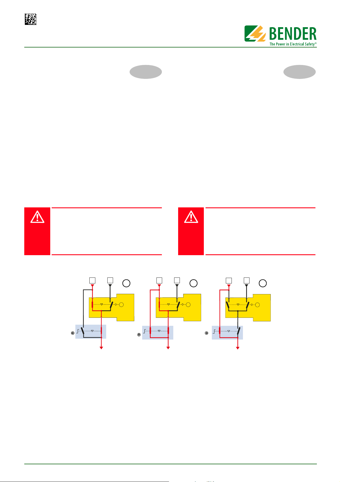
Funktionsbeschreibung
Das Umschaltgerät ATICS® muss auf Leitung 1 geschaltet sein.
Der am Umschaltgerät ATICS® montierte Hilfskontakt erkennt die
Schaltposition des Umschaltgerätes und bewirkt, dass die grüne
Leuchte „Freigabe Bypass“ signalisiert.
A Im Normalbetrieb steht der Drehgriff des Bypass-Schalters
ATICS-BP-3-… in Schaltposition „I“ bzw. „Normal“. Der
Drehgriff darf nun betätigt werden. Sobald diese Schaltposition verlassen wird, wird durch den am Bypass-Schalter
montierten Hilfskontakt eine Alarmmeldung „Handbetrieb“ an den digitalen Eingang IN1 des ATICS® gegeben.
Diese Alarmmeldung erscheint im Display des ATICS® und
wird gleichzeitig über den BMS-Bus gemeldet (z.B. an die
Gebäudeleittechnik (GLT)).
ATICS-BP-3-SET_D00161_00_M_DEEN/06.2014
Functional description
The ATICS® transfer switching device has to be connected to
Line 1. The auxiliary contact installed on the ATICS® recognises
the switching position of the transfer switching device with the
effect that the green LED signals "Bypass enabled".
A In normal operating condition, the rotary handle of the
ATICS-BP-3-… bypass switch is in switch position "I" resp.
in "Normal" position. Then the rotary handle may be acti-
contact installed in the bypass switch sends the alarm
vated. As soon as this switch position is left, the auxiliary
message "Manual mode" to the digital input IN1of the
ATICS®. This alarm message appears on the ATICS's display
und will simultaneously be signalled via the BMS bus (e.g.
to SCADA systems).
1
Page 2
ATICS-BP-3-63A-SET, ATICS-BP-3-80A-SET
DANGER
III
1
2
4
6
5
7
8
6109
3
11
GEFAHR
B In Schaltposition „I+II“ erfolgt die Speisung des Ausgangs
redundant über ATICS® und den Bypass-Schalter. Diese
Schaltposition darf nur genutzt werden, um sofort weiter
auf die nächste Schaltposition zu schalten.
C In Schaltposition „II“ bzw. „Bypass“ wird der Ausgang nur
noch über den Bypass-Schalter gespeist. Die Prüfung oder
der Austausch des Umschaltgerätes ATICS® ist nun ohne
Spannungsunterbrechung auf Leitung 3 möglich.
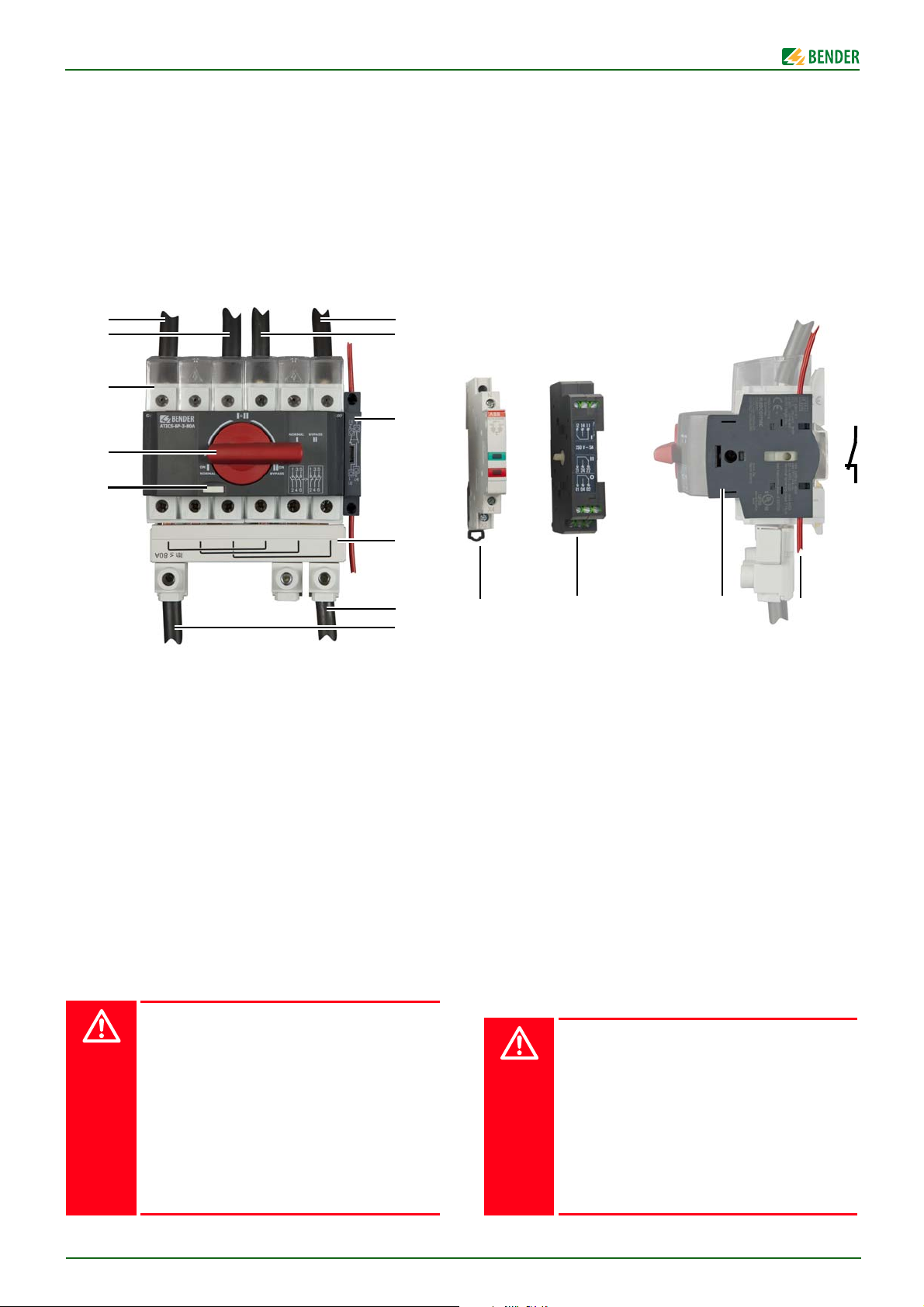
Frontansicht
B In switch position "I+II", the power to the output is redun-
dantly supplied from the ATICS® and the bypass switch.
This switch position is only to be used to switch immediately to the next switch position.
C In switch position "II", resp. "Bypass", the power to the out-
put is supplied from the bypass switch only. Now it is possible to test or replace the ATICS® transfer switching device
without interruption of the power supply on Line 3.
Front view
Legende der Frontansicht
1 Abschließvorrichtung für Drehgriff
2 Drehgriff (hier in Schaltposition „I“ bzw. „Normal“)
3 Klemmenabdeckung
4 Anschluss an Ausgang ATICS®
5 Anschluss an bevorzugte Leitung
6 Hilfskontakt für Alarmmeldung „Handbetrieb“
7Brücke
8Abgang zum Verteiler
9 Leuchtmelder grün/rot
10 Hilfskontakt für ATICS
11 Anschluss Hilfskontakt (Kontakte 1 und 2)
Montage und Anschluss
Das Gehäuse eignet sich:
- zum Einbau in Installationsverteiler DIN 43871
- zur Schnellmontage auf Hutprofilschiene DIN EN 60715
- zur Schraubmontage
Lebensgefahr durch Stromschlag
Bei Berühren unter Spannung stehender Anlagenteile besteht die Gefahr eines elektrischen Schlages.
Stellen Sie vor Einbau des Gerätes und vor Arbeiten
an den Anschlüssen des Gerätes sicher, dass die Anlage spannungsfrei ist.
Wird ATICS® durch einen Bypass-Schalter ATICS-BP3-… überbrückt, so sind die für Arbeiten unter Spannung geltenden Regeln zu beachten.
An den Kontakten der Leitung 1 liegt Netzspannung.
Steckvorrichtung darf nur am isolierten Teil angefasst werden.
Legend to the front view
1 Locking device for the rotary handle
2 Rotary handle (here in switch position "I" resp. in "Nor-
mal" position)
3 Terminal cover
4 Connection to the ATICS® output
5 Connection to the preferred line
6 Auxiliary contact for alarm message "Manual mode"
7Bridge
8 Outgoing line to the distribution board
9 Indicator light green/red
10 Auxiliary contact for ATICS
11 Connection to auxiliary contact (contacts 1 and 2)
Installation and connection
The enclosure is suitable for:
- installation into standard distribution panels in accordance with
DIN 43871
- DIN rail mounting acc. to DIN EN 60715; IEC 60715
- screw mounting
Risk of fatal injury from electric shock
Touching live parts of the system carries the risk of
electric shock.
Before fitting the enclosure and working on the device connections, make sure that the power supply
has been disconnected and the system is dead.
If the ATICS® is bypassed by an ATICS-BP-3-… bypass
switch, then the regulations which apply to working
on live parts must be followed.
Mains voltage at the contacts of Line 1. Plug must not
be touched unless the part is isolated.
2
ATICS-BP-3-SET_D00161_00_M_DEEN/06.2014
Page 3
ATICS-BP-3-63A-SET, ATICS-BP-3-80A-SET
1
2
35
52,5 *
105 8,8 **
85 *
76
42,5
95
52,5 * 84
8,75
17,5
M5 / 0,2 8,75
!
1
2
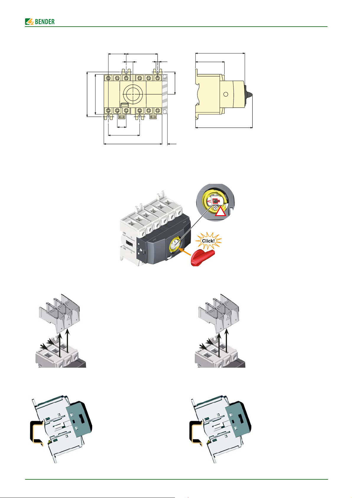
Maßbild
Alle Maße in mm
* Maße für Schraubmontage auf Platte
** Zusätzlicher Platzbedarf für Hilfskontakt
Drehgriff montieren
Dimension diagram
All dimensions in mm
* Dimensions for screw mounting on plate
** Additional space required for the auxiliary contact
Mounting of the rotary handle
Klemmenabdeckung demontieren
Montage auf Hutschiene
1. Klemmenabdeckung
durch kräftiges Ziehen
lösen,
2. … dann nach oben
abnehmen.
1. ATICS-BP-3-… auf den
oberen Rand der Hutschiene aufsetzen.
2. ATICS-BP-3-… durch
leichten Druck einrasten
lassen. Durch leichtes
Ziehen am unteren Teil
des Gehäuses prüfen, ob
Verriegelungsschieber
richtig eingerastet ist.
Removing the terminal cover
1. Pull strongly to loosen
the terminal cover
2. … then remove it in
upward direction.
Mounting on DIN rail
1. Place the ATICS-BP-3-…
on the top edge of the
rail.
2. Snap the ATICS-BP-3-…
into place with slight
pressure. Check that the
slide lock is properly
snapped into position by
pulling slightly the lower
part of the enclosure.
ATICS-BP-3-SET_D00161_00_M_DEEN/06.2014
3
Page 4

ATICS-BP-3-63A-SET, ATICS-BP-3-80A-SET
DANGER
CAUTION
DANGER
GEFAHR
VORSICHT
Slotted head 3,0 mm
4,4 lb-i n 0,5 Nm
6 mm / 0,236 "
# 20 to # 14 AWG
0,5 to 2,5 mm
2
0,5 to 1,5 mm
2
# 20 to # 16 AWG
Posidriv PZ2
8,8 lb-i n 1N m
20 mm
Posidriv PZ2
8,8 lb-in 1N m
35 mm
2 MAX
!
GEFAHR
Schraubmontage auf Platte
Befestigungsschrauben dürfen nicht zu dicke
Schraubenköpfe oder Unterlegscheiben haben, damit Spannungsabstände zu aktiven Leitern groß genug sind. Bei Montage auf leitendem Material: Platte
erden und unter den Bereich der Anschlüsse Isolierstoff unterlegen. Die Auswahl der Montageplatte, der
Schrauben und das Beachten der Anzugsmomente
liegt in der Verantwortung des mit der Montage betrauten Personals.
ATICS® mit Befestigungsschrauben M5 auf Montageplatte befestigen (siehe „Maßbild“).
Hilfsschalter am ATICS montieren
Zerstörungsgefahr
Zu lange Schrauben können ATICS zerstören!
Schraubenlänge gemäß Zeichnung beachten.
Screw mounting on plate
Provide for sufficient distance to adjacent live conductors by using mounting screws with flat screw
heads and flat washers. If mounted on electrically
conductive material: the mounting plate has to be
earthed and the area under the terminals has to be
covered with insulating material.
It is the responsibility of the mounting staff to select
the appropriate mounting plate and mounting
screws and to keep the prescribed torque setting.
Fasten the ATICS® to the mounting plate with M5 mounting
screws (see "dimension diagram").
Fitting an auxiliary contact to the ATICS
Risk of destruction
Screws that are too long may damage the ATICS!
It is essential to observe the screw length specified in
the illustration below.
Anschluss
Lebensgefahr durch Stromschlag
Leitungen können sich lösen und herausfallen, wenn
die Aderenden verzinnt sind oder die Anschlussschrauben nicht fest genug angezogen sind.
Zum Anziehen der Anschlussschrauben einen Drehmomentschlüssel benutzen.
Alle Schrauben regelmäßig auf festen Sitz prüfen.
1. Brücke montieren (siehe Bild „Frontansicht“)
2. ATICS-BP-3-… gemäß dem folgenden Anschlussbeispiel
anschließen.
Für den Anschluss der Leitungen die Abisolierlänge 12 mm
beachten und keine Aderendhülsen verwenden. Kreuzschlitzschraubendreher PZ2 oder Schlitzschraubendreher 6,5 x 1,2
mm verwenden. Anzugsmoment: 3,5 Nm.
3. Klemmenabdeckungen montieren.
Connection
Risk of fatal injury from electric shock
The lines can come loose and fall out if the wire ends
are tinned or the connection screws have not been
tightened enough.
Use a torque wrench to tighten the terminal screws.
Check all the screws on a regular basis to make sure
they are seated tightly.
1. Install the bridge (see figure "Front view")
2. Connect the ATICS-BP-3-… according to the following
connection example.
Take a stripping length of 12 mm into consideration and
do not use ferrules when connecting the lines. Use a PZ2
Phillips screwdriver or slotted screwdriver of 6.5 x 1.2 mm.
Tightening torque: 3.5 Nm.
3. Install terminal covers.
4
ATICS-BP-3-SET_D00161_00_M_DEEN/06.2014
Page 5

ATICS-BP-3-63A-SET, ATICS-BP-3-80A-SET
CAUTION
WARNING
Leitung/Line 1
AC 230 V
50 Hz
Leitung/Line 2
AC 230 V
50 Hz
Trenntrafo/
Isolating
transformer
230/230 V
L1 L2
IT-Verteiler/
IT distribution board
AC 230 V 50 Hz
*Diese Klemmen sind ausschließlich
für zukunftige Erweiterungen bestimmt!
*These terminals are solely intended
for future extensions!
Relaisausgang/
Relay output
Freigabe
Bypass/
Bypass
enabling
Min. 2 Gruppen MK2430/MK800 bzw. TM800
Min. 2 groups of MK2430 / MK800 resp. TM800
Unabhängige Versorgungsleitungen/
Independent supply lines
AC 230 V 50 Hz
grau/grey grün/green schwarz/black
H1
VORSICHT
WARNUNG
Inbetriebnahme
Zerstörungsgefahr durch falschen Anschluss
Vor der Inbetriebnahme den ordnungsgemäßen Anschluss des Geräts prüfen.
Insbesondere auf Polung der Leitungen achten.
Kurzschlussgefahr
ATICS® nur betätigen, wenn
1. ATICS® auf Schaltposition „I“ und
2. grüne Leuchte „Freigabe Bypass“ leuchtet.
Bypass-Schalter ATICS-BP-3-… immer zügig umschalten; nie auf Schaltposition „I+II“ stehen bleiben!
Ein Schild mit diesem Hinweis muss in der Nähe des
Bypass-Schalters angebracht sein.
1. Bypass-Schalter ATICS-BP-3-… in Schaltposition „I“ bzw.
„Normal“ schalten.
2. Netzspannung einschalten.
3. Im „Einstellmenü 6: Dig. Eingang“ muss eingestellt sein:
– 1. Funktion: Bypass
– 2. Ansprechwert: 0V
– 3. T(on ) Ansprechverzögerung: 100 ms
– 4. T(off ) Rückfallverzögerung: 100 ms
4. Das Umschaltgerät ATICS® auf Leitung 2 schalten. Die grüne
Leuchte „Freigabe Bypass“ darf in dieser Schaltposition
leuchten. Die rote Leuchte
ATICS-BP-3-SET_D00161_00_M_DEEN/06.2014
muss
leuchten.
Commissioning
Risk of destruction if connected incorrect
Prior to commissioning ensure that the device is
properly connected.
In particular, be sure to observe the correct polarity of
the connecting wires.
Risk of short-circuit
The ATICS® may only be operated when
1. The ATICS® is in switch position "I" and
2. the "Enable bypass" indicator lights up green.
Always change the switch position of the
ATICS-BP-3-… bypass switch quickly; never remain
in switch position "I+II"!
A warning sign with such a reference is to be placed
in the vicinity of the bypass switch.
1. Set the ATICS-BP-3-… bypass switch to position "I" resp. to
"Normal" position.
2. Switch the mains voltage on.
3. The following settings are to be set in the "Settings menu 6:
Digital Input":
– 1. Mode: Bypass
– 2. Resp. value: 0V
nicht
– 3. T(on ) Response delay: 100 ms
– 4. T(off ) Delay on release: 100 ms
5
Page 6

ATICS-BP-3-63A-SET, ATICS-BP-3-80A-SET
5. Die Klarsichtabdeckung des Umschaltgeräts ATICS® öffnen
und mit Sechskantschlüssel auf Position „0“ schalten. Die
grüne Leuchte „Freigabe Bypass“ darf auch in dieser Schaltpo-
nicht
sition
leuchten. Die Klarsichtabdeckung des Umschalt-
geräts ATICS® wieder schließen.
6. Das Umschaltgerät ATICS® auf Leitung 1 schalten. Die grüne
Leuchte „Freigabe Bypass“
muss
in dieser Schaltposition
leuchten. Falls nicht: Ursache suchen und beseitigen.
7. Nur wenn die grüne Leuchte „Freigabe Bypass“ leuchtet:
Bypass-Schalter ATICS-BP-3-… in Schaltposition „II“ bzw.
„Bypass“ schalten. Das Umschaltgerät ATICS® muss die Meldung „Handbetrieb“ anzeigen.
8. Bypass-Schalter ATICS-BP-3-… zurück in Schaltposition „I“
bzw. „Normal“ schalten.
Bedienung
Bedienungshandbuch des Umschaltgeräts ATICS® beachten, insbesondere die Hinweise in folgenden Kapiteln:
• Betrieb mit Bypass-Schalter
• ATICS® austauschen
Drehgriff mit Vorhängeschloss abschließen
Der Drehgriff kann nur in der Schaltposition „I“ bzw. „Normal“ abgeschlossen werden. Bügeldurchmesser des Vorhängeschlosses:
max. Ø 5 mm / min. Ø 4 mm.
4. Switch the ATICS® to Line 2. The green "Enable Bypass" indicator light must
cator light
not
light up in this switch position. The red indi-
must
light.
5. Open the transparent cover of the ATICS® and use an Allen key
to switch to position "0". Also in this switch position, the green
"Enable Bypass" indicator light must
not
light. Then close the
transparent cover of the ATICS® transfer switching device.
6. Switch the ATICS® to Line 1. The green "Enable Bypass" indicator
must
light in this switch position. If not: Identify the cause
and eliminate the error.
7. Only when the "Enable Bypass" indicator lights up green: Set
the ATICS-BP-3-… bypass switch to position "II" resp. to
"Bypass" position. The ATICS® transfer switching device must
display the message "Manual mode".
8. Reset the ATICS-BP-3-… bypass switch to position "I" resp.
"Normal".
Operation
Refer to the instructions in the operating manual of the ATICS® transfer switching device, in particular consider the following chapters:
• Operation with the bypass switch
• Replace the ATICS®
Lock the rotary handle with a padlock
It is only possible to lock the rotary handle in switch position "I"
resp. in "Normal" position. Padlock shackle diameter:
max. Ø 5 mm / min. Ø 4 mm.
1. Abschließvorrichtung herausziehen
2. Vorhängeschloss einhängen und verschließen. Die Schaltposition kann erst wieder nach Entfernen des Schlosses und Einschieben der Abschließvorrichtung geändert werden.
Technische Daten Bypass-Schalter ATICS-BP-3-…
Isolationskoordination nach IEC 60664-1
Bemessungsspannung ....................................................................................................... AC 415 V
Bemessungs-Stoßspannung/Verschmutzungsgrad ........................................................... 8 kV / 3
Leistungsteil/Schaltglieder
Schaltfolge ......................................................................................................................... I - I+II - II
Kontaktbemessungsspannung U
....................................................................................... AC 400 V
e
Kontaktbemessungsstrom Ie........................................................ 80 A (AC-21A, AC-22A, AC-23A)
.......................... ................................................. .................................................. ............ 50 kA eff.
I
cc
.......................... ................................................. .................................................. .................. 800 V
U
i
U
.......................... .................................................. ................................................. .................8 kV
imp
Elektrische Lebensdauer ..................................................................................... 12000 Schaltspiele
Kontaktklasse................................... ................................................................ IIB (IEC 60255-0-20)
Vorsicherung.... .............................................................................................................max. 80 A gG
Anschluss .................................................................................................Schraubklemmen 35 mm²
6
1. Pull out locking device
2. Thread in padlock and close it. The switch position cannot be
changed until the lock has been removed and the locking
device has been pushed in.
Technical data ATICS-BP-3-… bypass switch
Insulation coordination acc. to IEC 60664-1
Rated insulation voltage......................................................................................... .............A C 415 V
Rated impulse voltage/pollution degree .............................................................................. 8 kV / 3
Power unit/ switching elements
Switching sequence ...........................................................................................................I - I+II - II
Rated contact voltage U
Rated contact current I
Icc.......................... .................................................. ................................................. .............50 kA eff.
.......................... .................................................. ................................................. ...................800 V
U
i
........................ .................................................. ................................................. ...................8 kV
U
imp
Electrical endurance, number of cycles ...................................................................................12000
Contact class ................................................................ .................................... IIB (IEC 60255-0-20)
Back-up fuse ................................................................................................................. max. 80 A gG
Connection screw terminals 35 mm²
..................................................................................................... AC 400 V
e
............................................................. 80 A (AC-21 A, AC-22 A, AC-23 A)
e
ATICS-BP-3-SET_D00161_00_M_DEEN/06.2014
Page 7

ATICS-BP-3-63A-SET, ATICS-BP-3-80A-SET
Anschlussklemmen
Nur Kupferleiter verwenden ................................................................................................ .. ≥75 °C
Leiterquerschnitt starr min. / max. ........................................................... 2,5 mm² … 1 x 35 mm²
.................................................................................................................... 2,5 mm² … 2 x 25 mm²
Abisolierlänge ........................................... ............................................................................. 12 mm
Anzugsmoment (Kreuzschlitzschraubendreher PZ2 oder Schlitzschraubendreher 6,5 x 1,2 mm)
.................................................................................................................................. ............. 4,5 Nm
Allgemeine Daten
Schockfestigkeit IEC 60068-2-27 (Gerät in Betrieb) ............. ..................................... 15 g / 11 ms
Dauerschocken IEC 60068-2-29 (Transport)............................................................... 40 g / 6 ms
Schwingungsbeanspruchung IEC 60068-2-6 (Gerät in Betrieb)....................... 1 g / 10…150 Hz
Schwingungsbeanspruchung IEC 60068-2-6 (Transport)................................. 2 g / 10…150 Hz
Umgebungstemperatur (Gerät in Betrieb) .......................................................... -25 °C…+40 °C
Umgebungstemperatur (bei Lagerung) ....................................................... ....... -40 °C…+70 °C
Klimaklasse nach DIN IEC 60721-3-3 ........................................................................................ 3K5
Betriebsart. .............................................................................. ...................................... Dauerbetrieb
Einbaulage ........................ .................................................................................................... beliebig
Schraubbefestigung........ ............................................................................. ........................... 4 x M5
Schnellbefestigung auf Hutprofilschiene.............................................. DIN EN 60715 / IEC 60715
Gewicht ............................................................................................................................ ca. 1200 g
Schutzart, Einbauten (DIN EN 60529) ....................................................................................... IP30
Schutzart, Klemmen (DIN EN 60529) ........................................................................................ IP20
Entflammbarkeitsklasse .................................................................................................... UL94 V-2
Technische Daten Hilfskontakt für ATICS-BP-3-…
Schaltglieder .................................................................................................... 1 Öffner / 1 Schließer
........................... .................................................................................10 A (AC-13) / 6 A (AC-15)
I
e
Ue.......................... ................................................. .................................................. .................. 230 V
Schraubklemmen ............. .................................................................................................... 1,5 mm²
Terminals
Only use copper conductors .................................................................................................. ≥75 °C
Wire cross section, rigid min. / max. ........................................................ 2.5 mm² … 1 x 35 mm²
................................................................................................................... 2.5 mm² … 2 x 25 mm²
Stripping length...................................................................................................................... 12 mm
Tightening torque (PZ2 Allen screw or slotted screwdriver 6.5 x 1.2 mm)
.................................................................................................................................. ............. 4.5 Nm
General data
Shock resistance IEC 60068-2-27 (device in operation)............................................. 15 g / 11 ms
Bumping IEC 60068-2-29 (Transport) .......................................................................... 40 g / 6 ms
Vibration resistance IEC 60068-2-6 (during operation) ..................................... 1 g / 10…150 Hz
Vibration resistance IEC 60068-2-6 (during transport) ....................................2 g / 10 … 150 Hz
Ambient temperature (device in operation) ....................................................... -25 °C…+40 °C
Ambient temperature (for storage) ........................................... .......................... -40 °C…+70 °C
Climatic class acc. to DIN IEC 60721-3-3 ....................................................................................3K5
Operating mode ......................................... ..................................................... continuous operation
Position .......................................................................................................................... any position
Screw mounting ...................................................................................................................... 4 x M5
DIN rail mounting acc. to DIN EN 60715 / IEC 60715
Weight ....................................................................................................................... approx. 1200 g
Degree of protection, internal components (DIN EN 60529)..................................................... IP30
Degree of protection, terminals (DIN EN 60529) ....................................................................... IP20
Flammability class ...............................................................................................................UL94 V-2
Technical data auxiliary contact for ATICS-BP-3-…
Switching elements............................................................................1 N/C contact / 1 N/O contact
............................................................................................................ 10 A (AC-13) / 6 A (AC-15)
I
e
Ue......................... .................................................. ................................................. ...................230 V
Screw-type terminals ................................................ ........................................................... 1.5 mm²
Technische Daten Hilfskontakt für ATICS®
Schaltglieder .............................................................. ................................................. 3 Wechsler ÖS
Kontaktbemessungsspannung............................................................................................. 250 VAC
Kontaktbemessungsstrom ........................................................................................... 5 A maximal
Gewicht .......................................... .......................................................................................0,037 kg
Technische Daten Leuchtmelder grün/rot
LED-Spannungsbereich .......................................................... 12-48 VAC/DC (Toleranz +/- 10 %)
Frequenz ..............................................................................................................................50/60 Hz
Isolationsspannung .................................................................................................................. 250 V
Einbautiefe .......................................................................................... .................................... 68 mm
Einbaubreite..... ........................................................................... 0.5 oder 1 Modul (9 oder 18 mm)
Gehäusefarbe ......................................... .................................................... ................grau, RAL 7035
Klimafestigkeit nach ....................................................................... IEC 60068-2-2 (trockene Hitze)
......................................................................................................... IEC 60068-2-30 (feuchte Hitze)
.........................................................................................................................IEC 60068-2-1 (Kälte)
Umgebungstemperatur........................................................................................ .-25 °C bis +55 °C
Lagertemperatur............................................................ ........................................-40 °C bis +70 °C
Anschlussquerschnitt (Cu) ................................... von 1 x 1 mm
.......................................................................................von 1 x 0,75 mm2 bis 2 x 1,5 mm2 flexibel
................................................................................................... mit Aderhülse oder Stiftkabelschuh
Anziehdrehmoment ...................................................................................................... 1,2 - 1,5 Nm
Normen .................................................................................................................... DIN EN 62094-1
Zulassungen................................................................................................................................. VDE
Verlustleistung ................................................ .......................................................................... 0.8 W
LED-Farbe...................... .......................................................................................................Grün, Rot
Gewicht .......................................... .........................................................................................0.04 kg
2
bis 1 x 6 mm2 oder 2 x 2,5 mm
Technical data auxiliary contact for ATICS®
Switching elements ................................................................................. 3 changeover contacts ÖS
Rated contact voltage.......................................................................................................... AC 250 V
Rated contact current .......................................................................................................... max. 5 A
Weight ..................................................................................................................................0.037 kg
Technical data indicator light green/red
LED voltage range ................................................................. AC/DC 12-48 V (tolerance +/-10 %)
Frequency ......................... ................................................................................................... 50/60 Hz
Insulation voltage ..................................................................................................... .................250 V
Installation depth ................................................................................................................... 68 mm
Mounting width ................................................................................ 0.5 or 1 module (9 or 18 mm)
Enclosure colour ........................................................................................................ grey, RAL 7035
Resistance to climatic conditions acc. to ..................................................IEC 60068-2-2 (dry heat)
............................................................................................................ IEC 60068-2-30 (damp heat)
......................................................................................................................... IEC 60068-2-1 (cold)
Ambient temperature ............................................. ............................................... -25 °C to +55 °C
2
Storage temperature .............................................................................................. -40 °C to +70 °C
Wire cross section (Cu).............................................from 1 x 1 mm
........................... ...........................................................from 1 x 0.75 mm2 to 2 x 1.5 mm2 flexible
............................................................................................ with connection sleeve or pin cable lug
Tightening torque.......................................................................................................... 1.2 - 1.5 Nm
Standards.............................. .............................................................................. ......DIN EN 62094-1
Certification................... ................................................... .............................................................VDE
Power dissipation ..................................................................................................................... 0.8 W
LED colour ......................................................................................................................... green, red
Weight ....................................................................................................................................0.04 kg
2
to 1 x 6 mm2 or 2 x 2.5 mm
2
Normen
Der Bypass-Schalter ATICS-BP-3-… entspricht den Vorschriften
DIN EN 60947-3; VDE 0660-107 und IEC 60947-3
ATICS-BP-3-SET_D00161_00_M_DEEN/06.2014
Standards
The ATICS-BP-3-… bypass switch corresponds to the requirements of the standards DIN EN 60947-3; VDE 0660-107 and IEC
60947-3
7
Page 8

ATICS-BP-3-63A-SET, ATICS-BP-3-80A-SET
BENDER Group
Bestellangaben
Typ/Type Bezeichnung Designation
ATI CS - BP3-63A-SET
ATI CS - BP3-80A-SET
ATI CS - BP3-63A
einzeln
Bypass-Schalter-Set bestehend aus:
- Bypass-Schalter 63 A einzeln, 3-polig,
Schaltfolge: I-I+II-II, mit Hilfskontakt,
Brücke, Klemmenabdeckung
- Hilfskontakt für ATICS
- Leuchtmelder grün/rot für Hutschienenmontage
Bypass-Schalter-Set bestehend aus:
- Bypass-Schalter 80 A einzeln, 3-polig,
Schaltfolge: I-I+II-II, mit Hilfskontakt,
Brücke, Klemmenabdeckung
- Hilfskontakt für ATICS
- Leuchtmelder grün/rot für Hutschienenmontage
Bypass-Schalter 63 A einzeln, 3-polig,
Schaltfolge: I-I+II-II, mit Hilfskontakt,
Brücke, Klemmenabdeckung
Bypass switch set consisting of:
- Bypass switch 63 A, 3 poles, operating
sequence: I-I+II-II, with auxiliary contact, bridge, cover
- Auxiliary contact for ATICS
- Signal lamp green/red for DIN rail
mounting
Bypass switch set consisting of:
- Bypass switch 80 A, 3 poles, operating
sequence: I-I+II-II, with auxiliary contact, bridge, cover
- Auxiliary contact for ATICS
- Signal lamp green/red for DIN rail
mounting
Bypass switch 63 A, 3 poles, operating
sequence: I-I+II-II, with auxiliary contact,
bridge, cover
Ordering details
Bemessungs-
betriebsstrom /
Rated
operational
current I
e
AC 63 A B 9205 7252
AC 80 A B 9205 7253
AC 63 A B 9205 7256
Art.-Nr. /
Art.No.
ATI CS - BP3-80A
einzeln
ATICS-HK Hilfskontakt für ATICS,
Leuchtmelder
Bypass-Schalter 80 A einzeln, 3-polig,
Schaltfolge: I-I+II-II, mit Hilfskontakt,
Brücke, Klemmenabdeckung
3 Wechselkontakte
Leuchtmelder grün/rot 12-48VAC/DC,
für Hutschienenmontage,
Breite: 9 mm
Alle Rechte vorbehalten.
Nachdruck und Vervielfältigung
nur mit Genehmigung des Herausgebers.
Änderungen vorbehalten!
© Bender GmbH & Co. KG
Bypass switch 80 A, 3 poles, operating
sequence: I-I+II-II with auxiliary contact,
bridge, cover
Auxiliary contact for ATICS,
3 changeover contacts
Signal lamp green/red 12-48VAC/DC, for
DIN rail mounting,
width: 9 mm
only with permission of the publisher.
AC 80 A B 9205 7257
B 9205 7258
B 9205 7259
All rights reserved.
Reprinting and duplicating
Subject to change!
© Bender GmbH & Co. KG
Bender GmbH & Co. KG Tel.: +49 6401 807-0 E-Mail: info@bender.de
Londorfer Str. 65
Postfach 1161
8
• 35305 Grünberg • Germany Fax: +49 6401 807-259 Web: http://www.bender.de
• 35301 Grünberg • Germany
ATICS-BP-3-SET_D00161_00_M_DEEN/06.2014
 Loading...