

Bender ATICS-BP-3-80A-SET, ATICS-BP-3-63A-SET Series Manual
Handbuch
DANGER
GEFAHR
I
III III III
II
I
II
M
M
I
II
M
ATICS
®
ATICS
®
ATICS
®
ATICS-BP ATICS-BP ATICS-BP
I II
I+II
A B C
540697-B
ATICS-BP-3-63A-SET, ATICS-BP-3-80A-SET
Bypass-Schalter-Set für ATICS®
Deutsch English
Bestimmungsgemäße Verwendung
Der Bypass-Schalter ATICS-BP-3-… ermöglicht die Prüfung und
den Austausch des Umschaltgerätes ATICS® ohne die Stromversorgung der Leitung hinter der Umschalteinrichtung zu unterbrechen. Die Betätigung erfolgt über einen abschließbaren
Drehgriff. Das Set besteht aus:
• Bypass-Schalter ATICS-BP-3-63A bzw. ATICS-BP-3-80A,
3-polig, Schaltfolge: I-I+II-II,
mit Hilfskontakt, Brücke und Klemmenabdeckung,
• Hilfskontakt für ATICS®
• Leuchtmelder grün für Hutschienenmontage
Sicherheitshinweise allgemein
Bestandteil der Gerätedokumentation sind neben diesem Datenblatt die beiliegenden „Wichtigen sicherheitstechnischen Hinweise für Bender-Produkte“.
Sicherheitshinweise gerätespezifisch
Kurzschlussgefahr, wenn Leuchte „Freigabe
Bypass“ nicht beachtet wird.
Ist ATICS® nicht auf die Leitung geschaltet, an die der
Bypass-Schalter angeschlossen ist, kann es zu einem
Kurzschluss zwischen Leitung 1 und Leitung 2 kommen.
Der Bypass-Schalter darf nur betätigt werden, wenn die
grüne Leuchte „Freigabe Bypass“ signalisiert.
Bypass switch set for ATICS®
Intended use
The ATICS-BP-3-… bypass switch set makes it possible to test and
replace the ATICS transfer switching device without interrupting
the power supply to the line downstream of the transfer switching device. The switch can be operated by means of a lockable rotary handle. The set consists of:
• 3-pole ATICS-BP-3-63A resp. ATICS-BP-3-80A bypass
switch, switching sequence: I-I+II-II,
with auxiliary contact, bridge and terminal cover
• Auxiliary contact for ATICS ®
• Indicator light, green, for DIN rail mounting
Safety instructions
The enclosed "Important safety instructions for Bender products"
are also part of the equipment documentation along with this instruction leaflet.
Device-specific safety information
Risk of short-circuit if the "Enable Bypass" light is
ignored.
If the ATICS® is not on the line to which the bypass
switch is connected, it is possible for a short-circuit to
occur between Line 1 and Line 2.
The bypass switch may only be operated when the
green LED lights signalling "Bypass enabled".
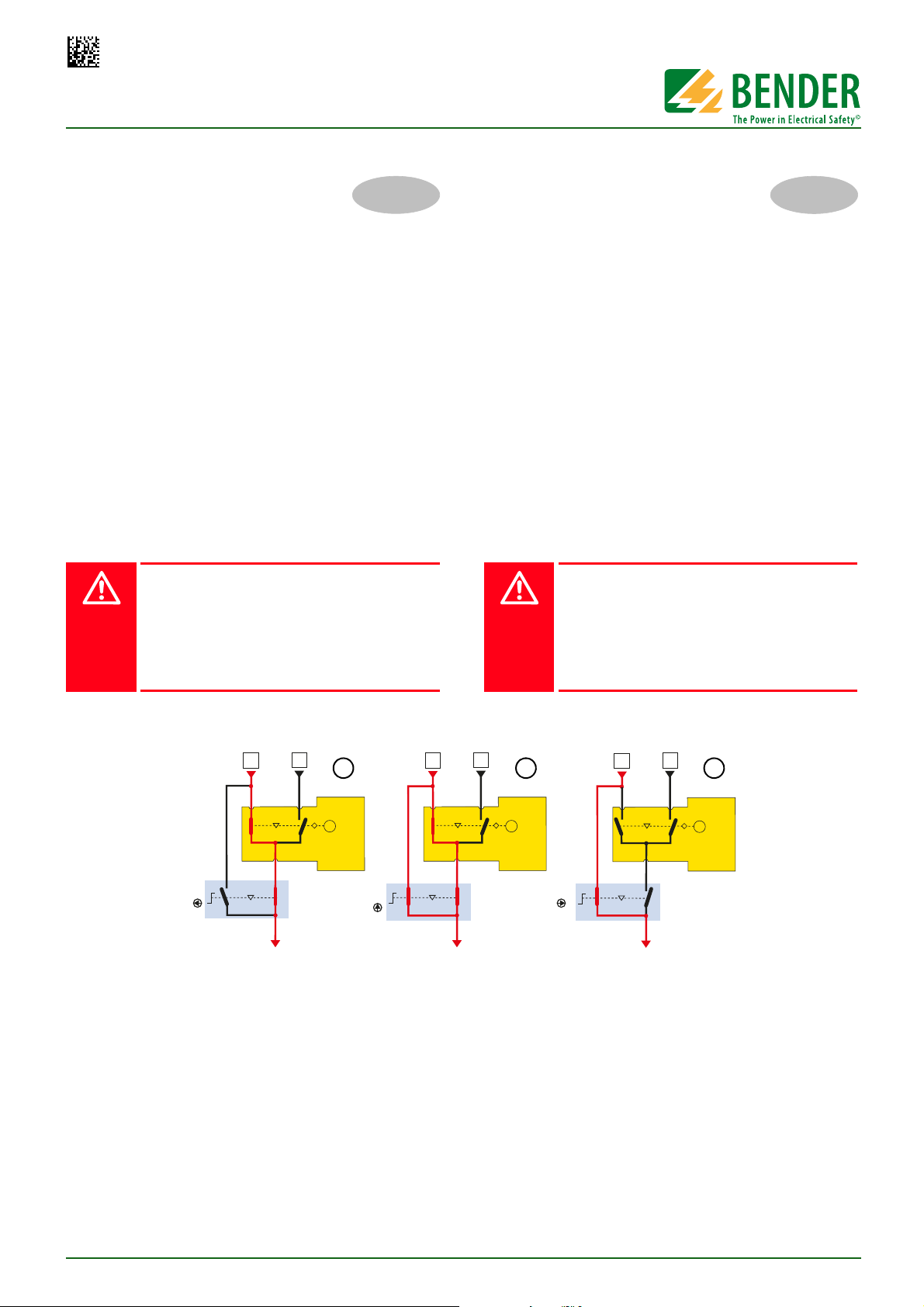
Funktionsbeschreibung
Das Umschaltgerät ATICS® muss auf Leitung 1 geschaltet sein.
Der am Umschaltgerät ATICS® montierte Hilfskontakt erkennt die
Schaltposition des Umschaltgerätes und bewirkt, dass die grüne
Leuchte „Freigabe Bypass“ signalisiert.
A Im Normalbetrieb steht der Drehgriff des Bypass-Schalters
ATICS-BP-3-… in Schaltposition „I“ bzw. „Normal“. Der
Drehgriff darf nun betätigt werden. Sobald diese Schaltposition verlassen wird, wird durch den am Bypass-Schalter
montierten Hilfskontakt eine Alarmmeldung „Handbetrieb“ an den digitalen Eingang IN1 des ATICS® gegeben.
Diese Alarmmeldung erscheint im Display des ATICS® und
wird gleichzeitig über den BMS-Bus gemeldet (z.B. an die
Gebäudeleittechnik (GLT)).
ATICS-BP-3-SET_D00161_00_M_DEEN/06.2014
Functional description
The ATICS® transfer switching device has to be connected to
Line 1. The auxiliary contact installed on the ATICS® recognises
the switching position of the transfer switching device with the
effect that the green LED signals "Bypass enabled".
A In normal operating condition, the rotary handle of the
ATICS-BP-3-… bypass switch is in switch position "I" resp.
in "Normal" position. Then the rotary handle may be acti-
contact installed in the bypass switch sends the alarm
vated. As soon as this switch position is left, the auxiliary
message "Manual mode" to the digital input IN1of the
ATICS®. This alarm message appears on the ATICS's display
und will simultaneously be signalled via the BMS bus (e.g.
to SCADA systems).
1
ATICS-BP-3-63A-SET, ATICS-BP-3-80A-SET
DANGER
III
1
2
4
6
5
7
8
6109
3
11
GEFAHR
B In Schaltposition „I+II“ erfolgt die Speisung des Ausgangs
redundant über ATICS® und den Bypass-Schalter. Diese
Schaltposition darf nur genutzt werden, um sofort weiter
auf die nächste Schaltposition zu schalten.
C In Schaltposition „II“ bzw. „Bypass“ wird der Ausgang nur
noch über den Bypass-Schalter gespeist. Die Prüfung oder
der Austausch des Umschaltgerätes ATICS® ist nun ohne
Spannungsunterbrechung auf Leitung 3 möglich.
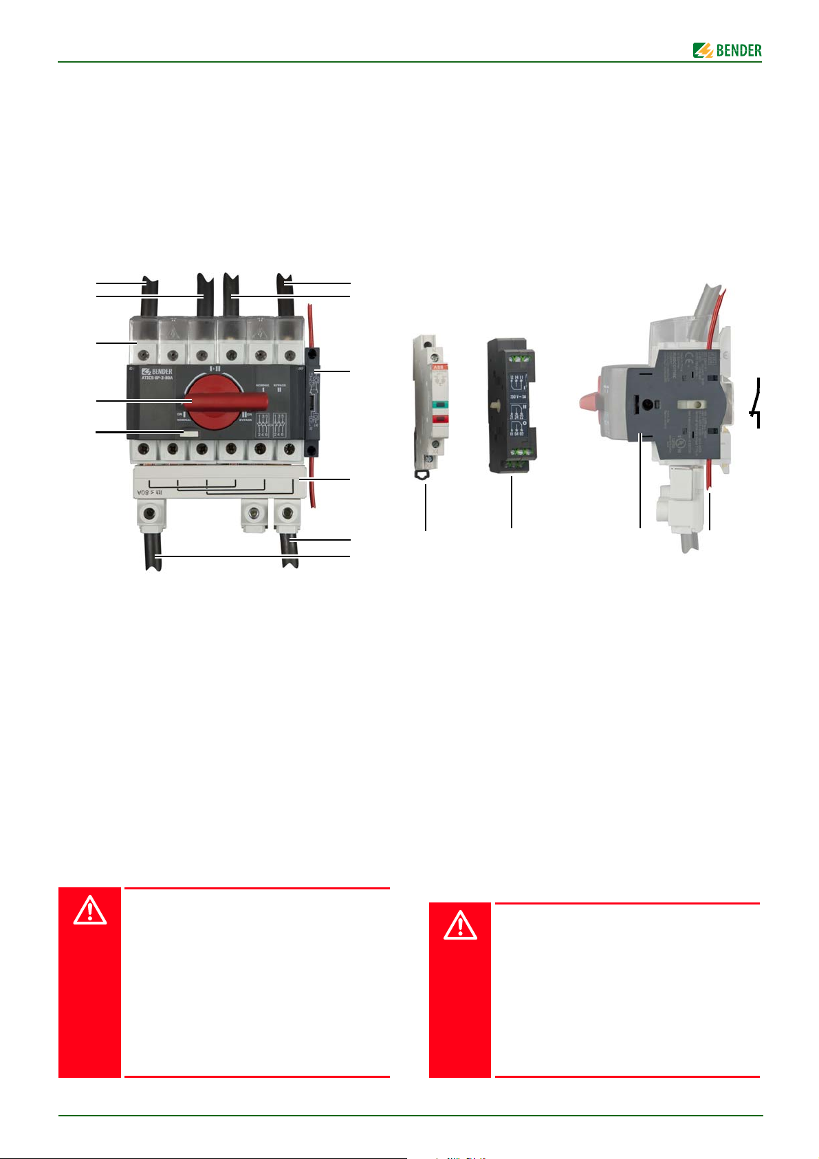
Frontansicht
B In switch position "I+II", the power to the output is redun-
dantly supplied from the ATICS® and the bypass switch.
This switch position is only to be used to switch immediately to the next switch position.
C In switch position "II", resp. "Bypass", the power to the out-
put is supplied from the bypass switch only. Now it is possible to test or replace the ATICS® transfer switching device
without interruption of the power supply on Line 3.
Front view
Legende der Frontansicht
1 Abschließvorrichtung für Drehgriff
2 Drehgriff (hier in Schaltposition „I“ bzw. „Normal“)
3 Klemmenabdeckung
4 Anschluss an Ausgang ATICS®
5 Anschluss an bevorzugte Leitung
6 Hilfskontakt für Alarmmeldung „Handbetrieb“
7Brücke
8Abgang zum Verteiler
9 Leuchtmelder grün/rot
10 Hilfskontakt für ATICS
11 Anschluss Hilfskontakt (Kontakte 1 und 2)
Montage und Anschluss
Das Gehäuse eignet sich:
- zum Einbau in Installationsverteiler DIN 43871
- zur Schnellmontage auf Hutprofilschiene DIN EN 60715
- zur Schraubmontage
Lebensgefahr durch Stromschlag
Bei Berühren unter Spannung stehender Anlagenteile besteht die Gefahr eines elektrischen Schlages.
Stellen Sie vor Einbau des Gerätes und vor Arbeiten
an den Anschlüssen des Gerätes sicher, dass die Anlage spannungsfrei ist.
Wird ATICS® durch einen Bypass-Schalter ATICS-BP3-… überbrückt, so sind die für Arbeiten unter Spannung geltenden Regeln zu beachten.
An den Kontakten der Leitung 1 liegt Netzspannung.
Steckvorrichtung darf nur am isolierten Teil angefasst werden.
Legend to the front view
1 Locking device for the rotary handle
2 Rotary handle (here in switch position "I" resp. in "Nor-
mal" position)
3 Terminal cover
4 Connection to the ATICS® output
5 Connection to the preferred line
6 Auxiliary contact for alarm message "Manual mode"
7Bridge
8 Outgoing line to the distribution board
9 Indicator light green/red
10 Auxiliary contact for ATICS
11 Connection to auxiliary contact (contacts 1 and 2)
Installation and connection
The enclosure is suitable for:
- installation into standard distribution panels in accordance with
DIN 43871
- DIN rail mounting acc. to DIN EN 60715; IEC 60715
- screw mounting
Risk of fatal injury from electric shock
Touching live parts of the system carries the risk of
electric shock.
Before fitting the enclosure and working on the device connections, make sure that the power supply
has been disconnected and the system is dead.
If the ATICS® is bypassed by an ATICS-BP-3-… bypass
switch, then the regulations which apply to working
on live parts must be followed.
Mains voltage at the contacts of Line 1. Plug must not
be touched unless the part is isolated.
2
ATICS-BP-3-SET_D00161_00_M_DEEN/06.2014
ATICS-BP-3-63A-SET, ATICS-BP-3-80A-SET
1
2
35
52,5 *
105 8,8 **
85 *
76
42,5
95
52,5 * 84
8,75
17,5
M5 / 0,2 8,75
!
1
2
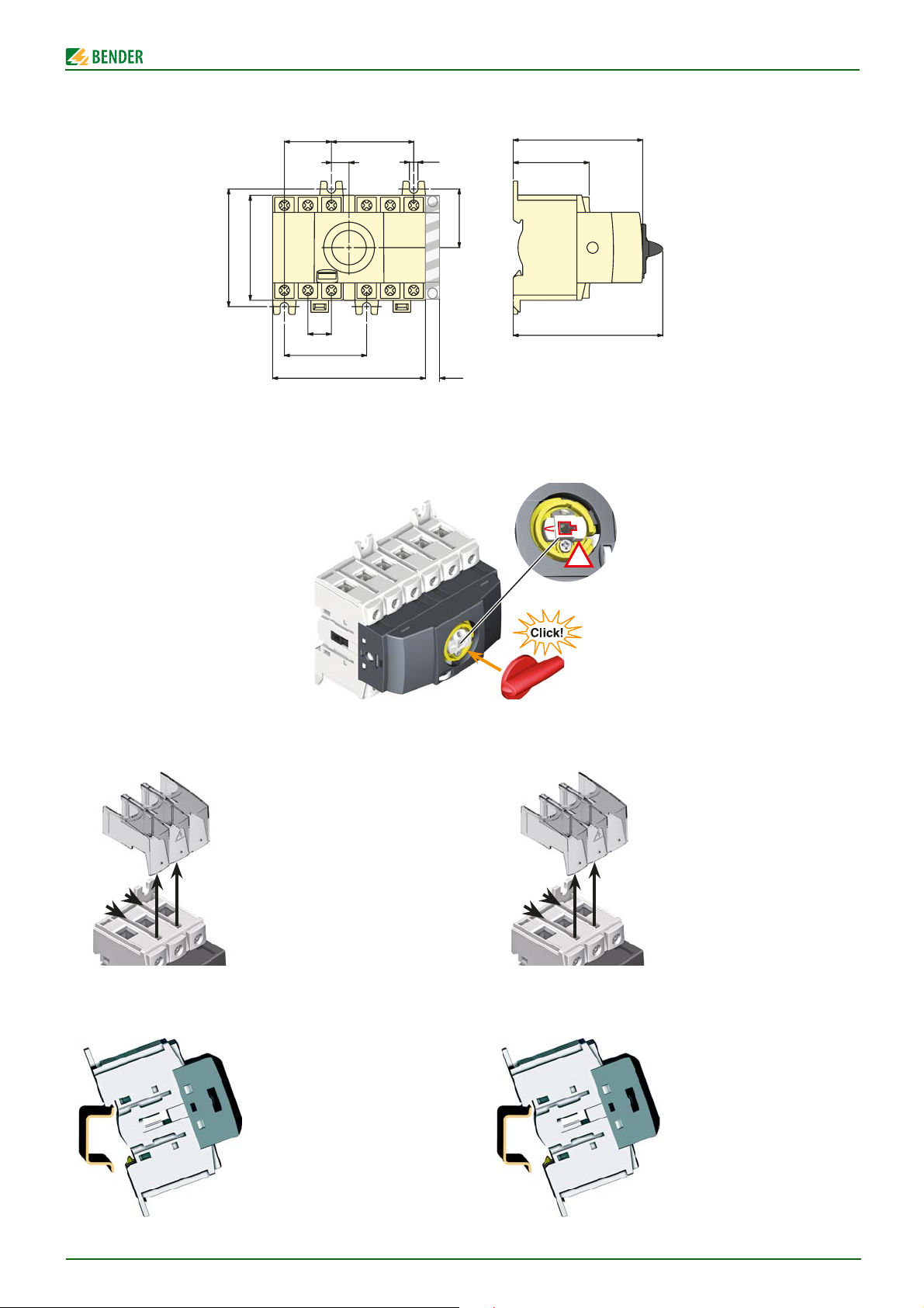
Maßbild
Alle Maße in mm
* Maße für Schraubmontage auf Platte
** Zusätzlicher Platzbedarf für Hilfskontakt
Drehgriff montieren
Dimension diagram
All dimensions in mm
* Dimensions for screw mounting on plate
** Additional space required for the auxiliary contact
Mounting of the rotary handle
Klemmenabdeckung demontieren
Montage auf Hutschiene
1. Klemmenabdeckung
durch kräftiges Ziehen
lösen,
2. … dann nach oben
abnehmen.
1. ATICS-BP-3-… auf den
oberen Rand der Hutschiene aufsetzen.
2. ATICS-BP-3-… durch
leichten Druck einrasten
lassen. Durch leichtes
Ziehen am unteren Teil
des Gehäuses prüfen, ob
Verriegelungsschieber
richtig eingerastet ist.
Removing the terminal cover
1. Pull strongly to loosen
the terminal cover
2. … then remove it in
upward direction.
Mounting on DIN rail
1. Place the ATICS-BP-3-…
on the top edge of the
rail.
2. Snap the ATICS-BP-3-…
into place with slight
pressure. Check that the
slide lock is properly
snapped into position by
pulling slightly the lower
part of the enclosure.
ATICS-BP-3-SET_D00161_00_M_DEEN/06.2014
3
 Loading...