

Bender ATICS-2-63A-DIO, ATICS-4-80A-DIO, ATICS-4-125A-DIO, ATICS-4-160A-DIO, ATICS-2-80A-DIO User Manual
Page 1
Manual
EN
ATICS-2-63A-DIO, ATICS-2-80A-DIO,
ATICS-4-80A-DIO, ATICS-4-125A-DIO,
ATICS-4-160A-DIO
Automatic transfer switching devices
for safety power supplies
Software version:
D333 V1.2x/D334 V1.2x/D335 V1.0x
ATICS-DIO_D00080_02_M_XXEN/08.2017
Page 2

Bender GmbH & Co. KG
P.O. Box 1161 • 35301 Gruenberg • Germany
Londorfer Straße 65 • 35305 Gruenberg • Germany
Tel.: +49 6401 807-0 • Fax: +49 6401 807-259
E-mail: info@bender.de • www.bender.de
Photos: Bender archives.
© Bender GmbH & Co. KG
All rights reserved.
Reprinting only with permission
of the publisher.
Subject to change!
Page 3

Table of Contents
1. Important information ........................................................................................... 7
1.1 How to use this manual ......................................................................................................... 7
1.2 Technical support: service and support ........................................................................... 8
1.2.1 First level support .................................................................................................................... 8
1.2.2 Repair service ............................................................................................................................ 8
1.2.3 Field service ................................................................................................................................ 8
1.3 Training courses ....................................................................................................................... 9
1.4 Delivery conditions ................................................................................................................. 9
1.5 Inspection, transport and storage ..................................................................................... 9
1.6 Warranty and liability ............................................................................................................. 9
1.7 Disposal .................................................................................................................................... 10
2. Safety instructions ............................................................................................... 11
2.1 General safety instructions ................................................................................................ 11
2.2 Work activities on electrical installations ..................................................................... 11
2.3 Intended use ........................................................................................................................... 11
2.4 Device-specific safety instructions ................................................................................. 12
2.5 General safety instructions ................................................................................................ 12
3. System description .............................................................................................. 13
3.1 Properties ................................................................................................................................. 13
3.1.1 Product description .............................................................................................................. 13
3.1.2 Changeover ............................................................................................................................. 13
3.1.3 Messages .................................................................................................................................. 13
3.1.4 Other functions ...................................................................................................................... 13
3.2 Functional safety ................................................................................................................... 14
3.2.1 Product life-cycle management ...................................................................................... 14
3.3 Application example ............................................................................................................ 15
3.4 ATICS® tasks ............................................................................................................................. 16
3.5 The ATICS® functions ........................................................................................................... 16
3.5.1 The automatic transfer switching device ..................................................................... 16
3.5.1.1 Time diagram: Changeover between the preferred and the redundant line
18
3.5.1.2 Time diagram: Staggered switching after complete power failure ............. 19
ATICS-DIO_D00080_02_M_XXEN/08.2017
3
Page 4

Table of Contents
3.5.1.3 Time diagram: Changeover to generator mode .................................................. 20
3.5.2 Monitoring the device functions ..................................................................................... 21
3.5.3 Power supply ........................................................................................................................... 21
3.5.4 Manual mode .......................................................................................................................... 21
3.6 ATICS-2-DIO front view ....................................................................................................... 22
3.7 ATICS-4-DIO front view ....................................................................................................... 23
4. Installation and connection ............................................................................... 25
4.1 Mounting .................................................................................................................................. 25
4.1.1 ATICS-2-DIO dimension diagram ..................................................................................... 26
4.1.2 ATICS-4-DIO dimension diagram ..................................................................................... 26
4.1.3 Removing the terminal covers .......................................................................................... 27
4.1.4 Mounting on DIN rail ............................................................................................................ 27
4.1.5 Screw mounting on plate ................................................................................................... 28
4.2 Connection ............................................................................................................................... 29
4.2.1 Short-circuit protection ....................................................................................................... 29
4.2.2 Connecting ATICS® safely ...................................................................................................30
4.2.3 Connection example: ATICS-2-DIO basic configuration .......................................... 33
4.2.4 Connection example: ATICS-4-DIO basic configuration .......................................... 34
4.2.5 Connection example: ATICS-2-DIO with bypass switch .......................................... 35
4.2.6 Connection example: ATICS-2-DIO with bypass switch .......................................... 36
4.2.7 Instructions for connection ................................................................................................37
4.2.7.1 BMS bus .............................................................................................................................. 37
4.2.7.2 MK… alarm indicator and test combination and TM… alarm indicator and
operator panels ............................................................................................................... 37
4.2.7.3 SCADA systems (Supervisory Control and Data Acquisition) ......................... 37
4.2.7.4 Bypass switch (optional) ............................................................................................... 37
4.2.8 Fastening, inserting and securing connections .......................................................... 38
4.3 Other functions ...................................................................................................................... 39
4.3.1 Sealing the transparent cover of the transfer switching device ........................... 39
4.3.2 Manual mode .......................................................................................................................... 39
4.3.3 Locking the transfer switching device with a padlock ............................................. 40
5. Commissioning, settings and testing ............................................................... 41
5.1 Design and installation ........................................................................................................ 41
5.1.1 Configure MK… or TM… .................................................................................................... 42
5.1.2 ATICS-2-DIO: Messages on the BMS bus (channel use) ........................................... 42
5.1.3 ATICS-4-DIO: Messages on the BMS bus (channel use) ........................................... 43
5.1.4 Tests, decommissioning ...................................................................................................... 44
5.2 Setting and testing according to the checklist ........................................................... 45
4
ATICS-DIO_D00080_02_M_XXEN/08.2017
Page 5

Table of Contents
5.3 Addressing example ............................................................................................................ 46
6. Operation ............................................................................................................... 47
6.1 Operating and display elements ..................................................................................... 47
6.2 Quick reference guide ......................................................................................................... 48
6.2.1 ATICS-2-DIO: Display under normal operating conditions .................................... 48
6.2.2 ATICS-4-DIO: Display under normal operating conditions .................................... 49
6.2.3 Display during fault condition ......................................................................................... 50
6.2.4 Test function ........................................................................................................................... 51
6.2.4.1 Test menu 1: Autom. changeover ............................................................................ 52
6.2.4.2 Test menu 2: Manual changeover ............................................................................ 53
6.2.4.3 Test menu 3: Last switch .............................................................................................. 54
6.2.4.4 Test menu 4: Generator ............................................................................................... 55
6.2.4.5 Test menu 5: Test communication .......................................................................... 56
6.2.5 Reset function ........................................................................................................................ 57
6.2.5.1 Reset menu 1: Alarm ..................................................................................................... 57
6.2.5.2 Reset menu 2: SwitchBackLock ................................................................................. 58
6.2.5.3 Reset menu 3: Changeover ......................................................................................... 59
7. Menu mode: Operation and setting ................................................................. 61
7.1 Switching on and calling up the main menu .............................................................. 61
7.2 Menu overview diagram .................................................................................................... 62
7.3 Main menu functions ........................................................................................................... 63
7.3.1 Menu 1: Alarm/meas.values .............................................................................................. 63
7.3.1.1 Alarm/meas. values ATICS-2-DIO ............................................................................. 63
7.3.1.2 Alarm/meas. values ATICS-4-DIO ............................................................................. 64
7.3.2 Menu 2: Changeover ............................................................................................................ 65
7.3.3 Menu 3: History/Logger ...................................................................................................... 66
7.3.3.1 Operating example: History ....................................................................................... 67
7.3.3.2 Operating example: Config.logger .......................................................................... 67
7.3.4 Menu 4: Settings .................................................................................................................... 68
7.3.4.1 Settings menu 1: Changeover ................................................................................... 69
7.3.4.2 Settings menu 2: Voltage ............................................................................................ 71
7.3.4.3 Settings menu 3: Current ............................................................................................ 72
7.3.4.4 Settings menu 4: Relay ................................................................................................. 73
7.3.4.5 Settings menu 5: Digital input ................................................................................... 75
7.3.4.6 Settings menu 6: Data logger .................................................................................... 77
7.3.4.7 Settings menu 7: Language ........................................................................................ 79
7.3.4.8 Settings menu 8: Interface .......................................................................................... 79
7.3.4.9 Settings menu 9: Clock ................................................................................................. 80
ATICS-DIO_D00080_02_M_XXEN/08.2017
5
Page 6

Table of Contents
7.3.4.10 Settings menu 10: Password ....................................................................................... 81
7.3.4.11 Settings menu 11: Service ........................................................................................... 82
7.3.5 Menu 5: Control ...................................................................................................................... 83
7.3.6 Menu 6: Digital Input ............................................................................................................ 83
7.3.7 Menu 7: Info ............................................................................................................................. 83
8. Troubleshooting ................................................................................................... 85
8.1 Fault and alarm messages .................................................................................................. 85
8.1.1 Plain text messages ............................................................................................................... 85
8.1.2 Messages with error code or service code ................................................................... 86
8.2 Frequently asked questions ............................................................................................... 88
9. Periodic verification and service ....................................................................... 91
9.1 Periodic verification .............................................................................................................. 91
9.2 Maintenance ............................................................................................................................ 92
9.3 Cleaning .................................................................................................................................... 92
9.4 Operation with bypass switch .......................................................................................... 92
9.5 Replace ATICS® ....................................................................................................................... 93
9.5.1 Removing the existing ATICS® .......................................................................................... 94
9.5.2 Installing a new ATICS® ........................................................................................................ 97
10. Technical data ..................................................................................................... 99
10.1 Tabular data ............................................................................................................................. 99
10.2 TÜV test report according to VDE0100 Part 710 ..................................................... 103
10.3 TÜV certificate regarding functional safety .............................................................. 104
10.4 Standards and certifications ........................................................................................... 105
10.5 Ordering details ................................................................................................................... 106
10.6 Additional documents ...................................................................................................... 107
INDEX ......................................................................................................................... 109
6
ATICS-DIO_D00080_02_M_XXEN/08.2017
Page 7
1. Important information
DANGER
WARNING
CAUTION
1.1 How to use this manual
This manual describes how to operate the ATICS® automatic transfer switching device.
Before using the devices, please read this operating manual, the supplement entitled "Important
safety instructions for Bender products" and the instruction leaflets supplied with the individual system components.
This manual is intended for qualified personnel working in electrical engineering and electronics, and in particular for those designing, installing and operating electrical equipment in the medical and non-medical sector.
In this manual, the two redundant supply lines of the power supply are labelled as follows:
– "Preferred supply" or "Preferred line" and
– "Second supply" or "Redundant line".
Devices with displays use the terms "Line 1" and "Line 2" in the text they indicate.
Always keep this manual within easy reach for future reference.
To make it easier for you to understand and revisit certain sections in this manual, we hav e used symbols to identify important instructions and information. The meaning of these symbols is explained
below:
This signal word indicates that there is a high risk of danger, that will result in
death or serious injury if not avoided.
This signal word indicates a medium risk of danger that can lead to death or serious injury, if not avoided.
This signal word indicates a low-level risk that can result in minor or moderate
injury or damage to property if not avoided.
This symbol denotes information intended to assist the user in making optimum
use of the product.
ATICS-DIO_D00080_02_M_XXEN/08.2017
7
Page 8

Important information
This manual has been compiled with great care. It might nevertheless contain errors and mistakes.
Bender cannot accept any liability for injury to persons or damage to property resulting from errors
or mistakes in this manual.
ATICS® is a registered trademark of Bender GmbH & Co. KG.
1.2 Technical support: service and support
For commissioning and troubleshooting Bender offers you:
1.2.1 First level support
Technical support by phone or e-mail for all
Bender products
Questions concerning specific customer applications
Commissioning
Troubleshooting
Telephone:
Fax:
In Germany only:
E-mail:
+4 19 640 807-76 0*
+4 640129 807- 59
0700BenderHelp (Tel. and Fax)
support@bender-service.de
1.2.2 Repair service
Repair, calibration, update and replacement service for Bender products
Repairing, calibrating, testing and analysing Bender products
Hardware and software update for Bender devices
Delivery of replacement devices in the event of faulty or incorrectly delivered Bender devices
Extended guarantee for Bender devices, which includes an in-house repair service or replace-
ment devices at no extra cost
Telephone:
Fax:
E-mail:
Please send the devices for repair to the following address:
+49 6401 807-780** (technical issues)
+49 6401 807-784**, -785** (sales)
+4 640179 807- 89
repair@bender-service.de
Bender GmbH, Repair-Service,
Londorfer Straße 65,
35305 Grünberg
1.2.3 Field service
On-site service for all Bender products
Commissioning, parameter setting, maintenance, troubleshooting for Bender products
Analysis of the electrical installation in the building (power quality test, EMC test,
thermography)
Training courses for customers
8
ATICS-DIO_D00080_02_M_XXEN/08.2017
Page 9

Important information
Telephone:
+49 6401 807-752**, -762 **(technical issues)
+49 6401 807-753** (sales)
Fax:
E-mail:
Internet:
+49 6401 807-759
fieldservice@bender-service.de
www.bender.de
*Available from 7.00 a.m. to 8.00 p.m. 365 days a year (CET/UTC+1)
**Mo-Thu 7.00 a.m. - 8.00 p.m., Fr 7.00 a.m. - 13.00 p.m.
1.3 Training courses
Bender is happy to provide training regarding the use of test equipment. The dates of training courses and workshops can be found on the Internet at www.bender-de.com -> Know-how -> Seminars.
1.4 Delivery conditions
Bender sale and delivery conditions apply.
For software products the "Softwareklausel zur Überlassung von Standard-Software als Teil von
Lieferungen, Ergänzung und Änderung der Allgemeinen Lieferbedingungen für Erzeugnisse und
Leistungen der Elektroindustrie" (software clause in respect of the licensing of standard software as
part of deliveries, modifications and changes to general delivery conditions for products and services in the electrical industry) set out by the ZVEI (Zentralverband Elektrotechnik- und Elektronikindustrie e. V.) (German Electrical and Electronic Manufacturer's Association) also applies.
Sale and delivery conditions can be obtained from Bender in printed or electronic format.
1.5 Inspection, transport and storage
Inspect the dispatch and equipment packaging for damage, and compare the contents of the package with the delivery documents. In the event of damage in transit, please contact Bender immediately.
The devices must only be stored in areas where they are protected from dust, damp, and spray and
dripping water, and in which the specified storage temperatures can be ensured.
1.6 Warranty and liability
Warranty and liability claims in the event of injury to persons or damage to property are excluded if
they can be attributed to one or more of the following causes:
Improper use of the device.
Incorrect mounting, commissioning, operation and maintenance of the device.
Failure to observe the instructions in this operating manual regarding transport,
commissioning, operation and maintenance of the device.
Unauthorised changes to the device made by parties other than the manufacturer.
Non-observance of technical data.
Repairs carried out incorrectly and the use of replacement parts or accessories not approved by
the manufacturer.
Catastrophes caused by external influences and force majeure.
Mounting and installation with device combinations not recommended by the manufacturer.
This operating manual, especially the safety instructions, must be observed by all personnel working
on the device. Furthermore, the rules and regulations that apply for accident prevention at the place
of use must be observed.
ATICS-DIO_D00080_02_M_XXEN/08.2017
9
Page 10

Important information
1.7 Disposal
Abide by the national regulations and laws governing the disposal of this device. Ask your supplier
if you are not sure how to dispose of the old equipment.
The directive on waste electrical and electronic equipment (WEEE directive) and the directive on the
restriction of certain hazardous substances in electrical and electronic equipment (RoHS directive)
apply in the European Community. In Germany, these policies are implemented through the "Electrical and Electronic Equipment Act" (ElektroG). According to this, the following applies:
Electrical and electronic equipment are not part of household waste.
Batteries and accumulators are not part of household waste and must be disposed of in accord-
ance with the regulations.
Old electrical and electronic equipment from users other than private households which was
introduced to the market after 13 August 2005 must be taken back by the manufacturer and
disposed of properly.
For more information on the disposal of Bender devices, refer to our website at www.bender-de.com
-> Service & support.
10
ATICS-DIO_D00080_02_M_XXEN/08.2017
Page 11
2. Safety instructions
DANGER
2.1 General safety instructions
Part of the device documentation in addition to this manual is the enclosed "Safety instructions for
Bender products".
2.2 Work activities on electrical installations
Only qualified personnel are permitted to carry out the work necessary to install, commission and run a device or system.
Risk of electrocution due to electric shock!
Touching live parts of the system carries the risk of:
An electric shock
Damage to the electrical installation
Destruction of the device
Before installing and connecting the device, make sure that the installation has been de-energised. Observe the rules for working on electrical installa-
tions.
If the device is used outside the Federal Republic of Germany, the applicable local standards and regulations must be complied with. The European standard EN 50110 can be used as a guide.
2.3 Intended use
Changeover devices are used everywhere there is dependence on high availability from the power
supply. The ATICS® transfer switching device is intended for the application described in the chapter
"System description". When the preferred supply fails, ATICS® automatically switches to the second
supply.
Areas of application:
Group 1 and 2 medical locations according to DIN VDE 0100-710 and
IEC 60364-7-710
Hospital main distribution boards (DIN VDE 0100-710)
Locations open to the public (DIN VDE 0100-718)
Emergency power supplies
Heating, air conditioning, ventilation, cooling
EDP, computer centres
Fire extinguisher and sprinkler systems
Several versions of ATICS® are available. They differ for example by changing over from two- or fourpole systems or by the load current (see chapter "ATICS® tasks" on page 16). Please heed the limits of
the range of application indicated in the technical data.
ATICS-DIO_D00080_02_M_XXEN/08.2017
11
Page 12
Safety instructions
WARNING
WARNING
In order to meet the requirements of applicable standards, customised parameter settings must be
made on the equipment in order to adapt it to local equipment and operating conditions.
Intended use includes following all the instructions in the operating manual and complying with the
test intervals.
Any use other than that described in this manual is regarded as improper.
2.4 Device-specific safety instructions
Failure to adjust settings may result in malfunction
The settings must be changed in order to adapt the ATICS® transfer switching device to the existing equipment. When doing so, follow the instructions in
chapter "5. Commissioning, settings and testing", page 41 et seq.
Functional safety according to IEC 61508 can only be guaranteed when
used properly
Please follow the instructions given in this operating manual and in the check
list.
In particular note the information on the pages: 14, 15, 16, 21, 59 and 88.
2.5 General safety instructions
Bender devices are designed and built in accordance with the state of the art and accepted rules in
respect of technical safety. However, the use of such devices may introduce risks to the life and limb
of the user or third parties and/or result in damage to Bender devices or other property.
Use Bender devices only:
–as intended
– in perfect working order
– in compliance with the accident prevention regulations and guidelines applicable at the
location of use
Eliminate all faults immediately which may endanger safety.
The device may not be opened.
Do not make any unauthorised changes and only use replacement parts and optional accesso-
ries purchased from or recommended by the manufacturer of the devices. Failure to observe
this requirement can result in fire, electric shock and injury.
Reference signs must always be clearly legible. Replace damaged or illegible signs immediately.
Make sure that the dimensions of the BSV (battery-supported safety power supply), the genera-
tor set and the whole wiring is adequate. Abide by the relevant, applicable national and international standards. In the event of an overload and short circuit, this is the only way to
guarantee the necessary safety and to ensure that the safety devices respond selectively.
If the device is overloaded by overvoltage or a short-circuit current load, it must be checked
and replaced if necessary.
The overvoltage protective device required by the standards VDE 0100-443 and VDE 0100-534
must be installed in the electrical installation or system.
12
ATICS-DIO_D00080_02_M_XXEN/08.2017
Page 13

3. System description
3.1 Properties
3.1.1 Product description
The ATICS® transfer switching devices provide all functions for changeover between two independent power supplies. The integration of both the electronic system and the switching elements in one
flat, compact device reduces space requirements in the switchgear cabinet, minimises the amount
of wiring, and reduces the fault probability. For maximum reliability, ATICS® was designed in strict
accordance with the guidelines for functional safety.
Connectors at all connecting wires in combination with bypass switches enable ATICS® to be tested
during ongoing operation. In case of need for service, it is possible to repair or replace the device
without interrupting the power supply. ATICS® considerably enhances the safety level in industry
and other sensitive environments like hospitals.
3.1.2 Changeover
Automatic changeover to the second (redundant) line on loss of the preferred supply or when
the values are outside the permissible voltage range
Voltage monitoring line 1/2 (input) and line 3 (output)
Automatic return to the preferred line on voltage recovery
Monitoring for short circuits at the output or at the distribution board downstream of the trans-
fer switching device avoids damaging switching operations
Manual operation, optionally locked with a padlock
3.1.3 Messages
Status indication of operating, warning and alarm messages via integrated graphic display
and external indication at MK2430/MK800/TM800 alarm indicator and operator panels
Automatic reminder for prescribed tests and service intervals
History memory for events, messages, tests and parameter changes
Exchange of information with alarm indicator and operator panels via BMS bus
3.1.4 Other functions
Automatic monitoring of all programme and data storage as well as essential internal compo-
nents and connecting wires for proper functioning
4 programmable relay outputs (alarm relays)
4 programmable digital inputs
ATICS-DIO_D00080_02_M_XXEN/08.2017
13
Page 14
System description
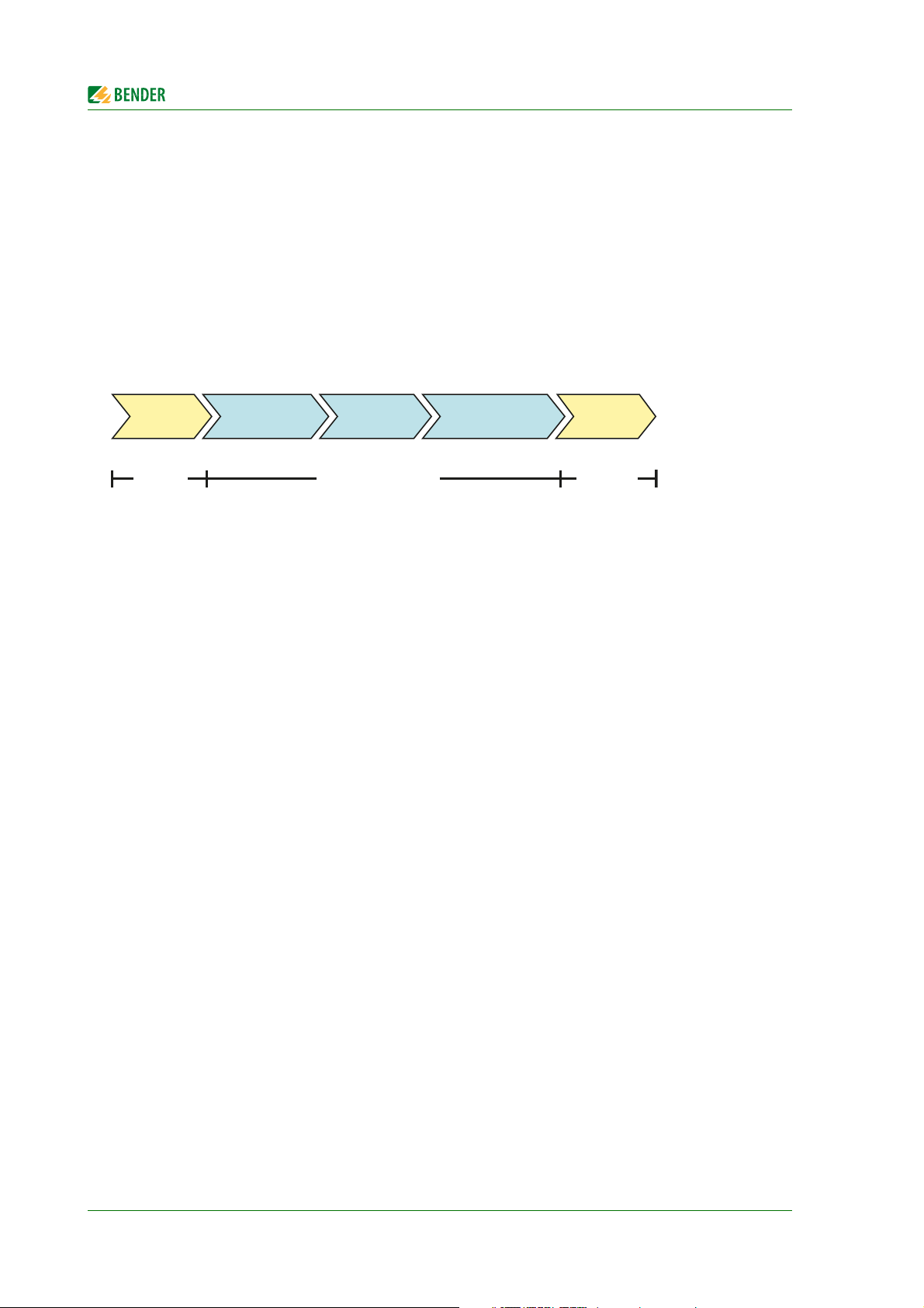
Production Commissioning RecyclingDecommissioningMaintenance
Bender plant operator Bender
3.2 Functional safety
Functional safety according to IEC 61508 guarantees safety from risks arising from malfunction when
used properly. ATICS® is suitable for use in safety-related systems according to SIL2. SIL stands for
"Safety Integrity Level".
3.2.1 Product life-cycle management
Safety must be guaranteed over the entire life cycle, from the time it is designed, developed, manufactured, commissioned, maintained to the time it is taken out of service.
Responsibility during the life cycle:
For detailed information refer to
chapter "5. Commissioning, settings and testing" on page 41
chapter "9. Periodic verification and service" on page 91
14
ATICS-DIO_D00080_02_M_XXEN/08.2017
Page 15
System description
I
II
I
II
U
1
U
2
U
3
I
computing centre
Anlage
betriebsbereit
MK800
NORMAL WARNING ALARM
ESC
TEST MENU
RCMS
ATI C S
M
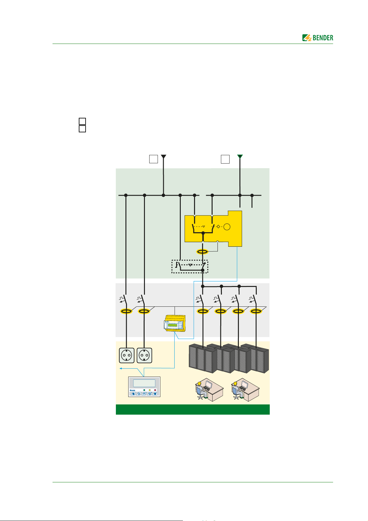
3.3 Application example
ATICS-2-63A-DIO: Changeover between the preferred and the redundant line
MK2430/MK800/TM800: Alarm at at least two points with independent power supplies for func-
tional safety
RCMS: RCMS460 or RCMS490 residual current monitors for localising residual and operating
currents in TT and TN-S systems
Preferred supply line
Redundant supply line (e.g. generator)
ATICS-DIO_D00080_02_M_XXEN/08.2017
15
Page 16

System description
3.4 ATICS® tasks
The ATICS® transfer switching device has the following capabilities:
Two-pole or four-pole changeover of the power supply
Voltage monitoring for the preferred supply (Line 1)
Voltage monitoring for the second supply (Line 2)
Voltage monitoring at the transfer switching device output (line 3)
Monitoring of the changeover switch for correct switch position
Internal functional testing, including checking the switching times
Communication to remote MK... alarm indicator and test combinations, and to TM… alarm indi-
cator and operator panels via BMS bus
Option for adjusting the time delay for the changeover process according to DIN VDE 0100-710
(VDE 0100 Part 710)
Possible field of application in systems according to DIN VDE 0100-710 (VDE 0100 Part 710) with
a changeover period ≤ 15 s or even ≤ 0.5 s
3.5 The ATICS® functions
3.5.1 The automatic transfer switching device
If the preferred supply fails, ATICS® ensures that the power supply is changed over safely.
The switch contacts are offset on a rotating shaft. This design prevents simultaneous switching of
line 1 and line 2. The switch has three positions:
1 Line 1 switched on
0 Both lines switched off
2 Line 2 switched on
Either line 1 or line 2 can be set as the preferred line (setting described in "Settings menu 1: Changeover" on page 69 or "Settings menu 5: Digital input" on page 75).
1. In normal operating condition (fault-free operation) the preferred supply is connected. ATICS®
will switch to the redundant line if:
– the preferred line fails
– the "TEST" button is pressed
– a digital input is configured to "TEST" and this input is enabled
– the setting "Preferred Line" is reconfigured to the other line
16
ATICS-DIO_D00080_02_M_XXEN/08.2017
Page 17
System description
WARNING
2. ATICS® will switch from the redundant line back to the preferred line if
– the voltage on the preferred line is restored
- the return transfer delay time t(2->1) has expired and no switching back interlocking
function is enabled
- immediately after pressing the "RESET" button or when the redundant line fails
(even when the switching back interlocking function is enabled)
– the setting "Preferred Line" is reconfigured to the other line
– the digital input is configured to "TEST" and this input is reset
– a test of the transfer switching device is active and the test period has elapsed
Failure to adjust delay times may result in malfunctions
The response delay t(on), the return transfer delay time t(2->1), the delay on release t(off) and the dead time t(0) of ATICS® are adjustable and must be adjusted
to the requirements of the specific case, the short-circuit calculation and the requirements of DIN VDE 0100-710 (VDE 0100 Part 710) for automatic changeover
devices (see chapter "Commissioning, settings and testing").
The factory settings guarantee a changeover period of t ≤ 0.5 seconds and switching back within 10
seconds when voltage is restored on the preferred supply. Therefore, ATICS® can be used in IT systems with a requirement for a changeover period t ≤ 0.5 s (IT systems with operating theatre lights,
endoscopic field illumination in operating theatres or other essential sources of light, etc.).
When there is a short circuit downstream of the transfer switching device, the transfer switching device must not continually change back and forth between the two lines. This can occur when the
short-circuit current is small and the transfer switching device switches faster than the short-circuit
breaker trips. ATICS® monitors the load current downstream of the transfer switching device in order
to detect a possible short circuit. If the preferred line fails and a short-circuit current is detected at
the same time, ATICS® does not switch over immediately but only once the circuit breaker has
tripped.
If ATICS® detects a supply failure or a fault, an alarm appears on the LCD, the "ALARM" LED lights up,
the alarm relay trips (if set) and this alarm is forwarded to other Bender devices (such as an alarm indicator and test combination) via the BMS bus.
Phase sequence direction errors are recognised and indicated on the LC display. Even so ATICS®
switches over to the redundant line.
ATICS-DIO_D00080_02_M_XXEN/08.2017
17
Page 18
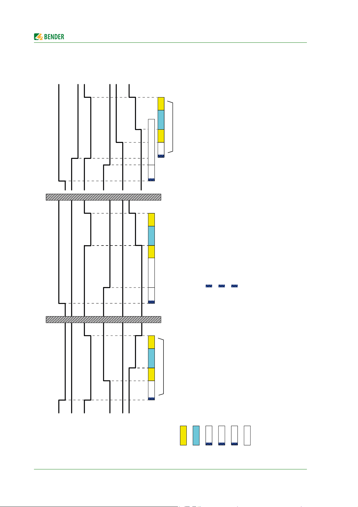
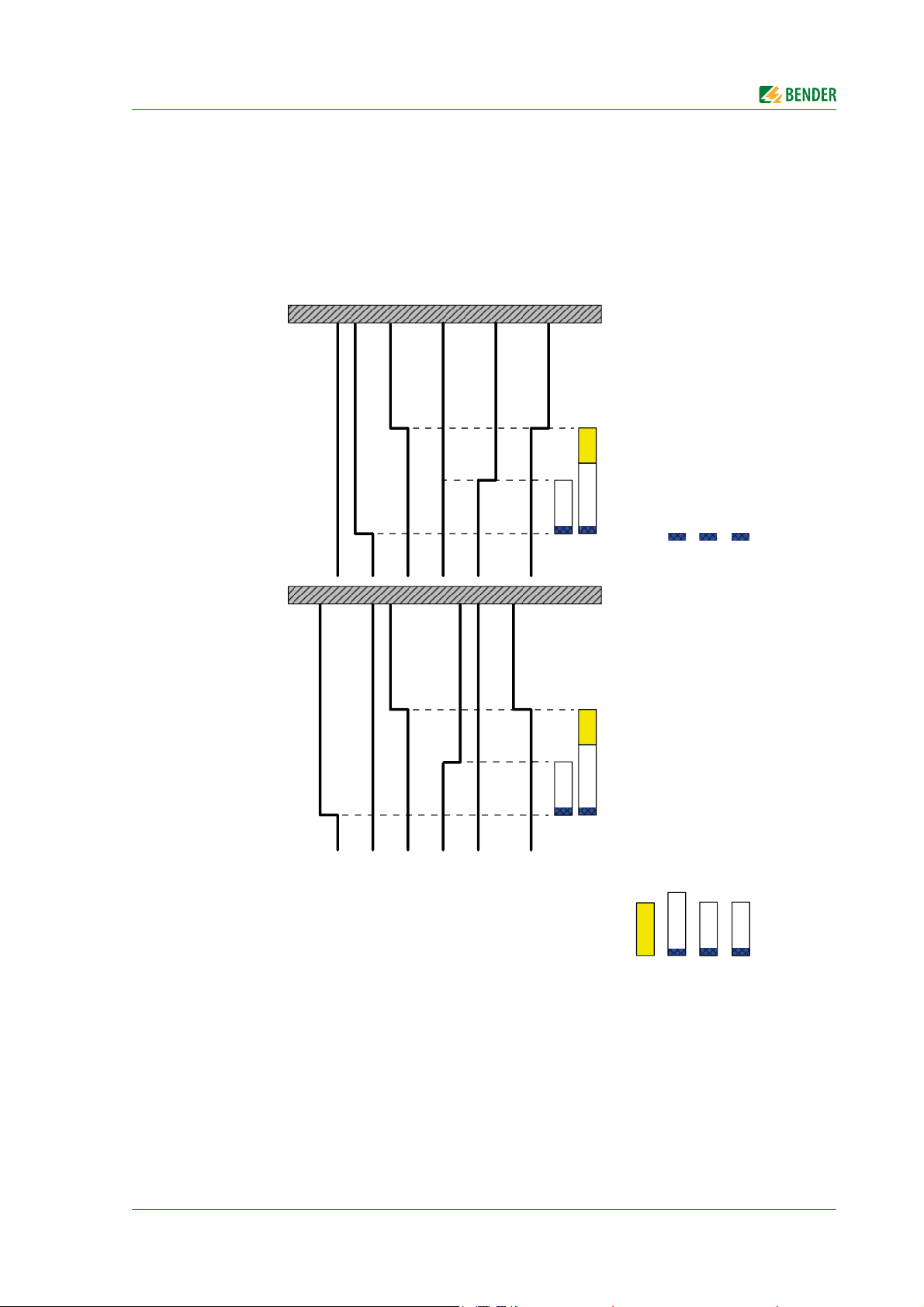
3.5.1.1 Time diagram: Changeover between the preferred and the redundant line
Note: Times are not shown to scale.
Example: Line 1 is set as the preferred line.
1
t(Imp)
System description
Switching back to Line 1
(if Line 2 has failed)
Switching back to Line 1
(normal operation with delay on relase)
t(2->1)
1
t(off)
t(0)
t(Imp)
2
t(on)
*2
0
2
1
t(Imp)
0
t(0)
t(Imp)
t(2->1)
1
t(off)
: Measuring time: approx. 50 ms
: Measuring time: approx. 50 ms
: Measuring time: approx. 50 ms
: Changeover period t(1->2) indicated during a test
: The return transfer delay time may differ from the changeover period (t(1->2)
*2
*1
Changeover to Line 2
(if Line 1 has failed)
Voltage
Line 1
Voltage
18
Line 2
Voltage
Output
Alarm Failure
ATICS
Line 1
2
t(Imp)
t(0)
*1
t(Imp)
1
t(on)
10
102
Alarm Failure
Line 2
Switch
position
Time
delay
: Response delay ALARM failure voltage Line 1
: Pulse time: 15 … 30 ms
t(0) : Dead time
t(Imp)
: Delay on release ALARM failure voltage Line 1
1
1
t(off)
t(on)
ATICS-DIO_D00080_02_M_XXEN/08.2017
: Response delay ALARM failure voltage Line 2
2
t(on)
t(2->1) : Return transfer delay time
Page 19
System description
102
Option: Staggered
switching after total
power failure
t(Start)
t(Imp)
0
1
Option: Staggered
switching after total
power failure
0
2
Voltage
Line 1
Switch
position
Voltage
Output
ATICS
Voltage
Line 2
Time
delay
Alarm failure
Line 1
Alarm failure
Line 2
t(Start)
: Switch-on delay after total power failure
: Delay on release ALARM failure voltage Line 1
Wenn die Spannung kommt, starten gleichzeitig t(off) und t(Anlauf). Die längere Zeit bestimmt das Verhalten.
t(Imp)
: Pulse time: 15 … 30 ms
: Measuring time: approx. 50 ms
: Measuring time: approx. 50 ms
t(off)
1
t(Start)
t(Imp)
t(off)
2
t(off)
1
: Delay on release ALARM failure voltage Line 2
: Measuring time: approx. 50 ms
t(off)
2
Note: Times are not shown to scale.
3.5.1.2 Time diagram: Staggered switching after complete power failure
After a complete power failure (i.e. no voltage on either of the power supplies) it is often necessary
to switch to the supply at staggered intervals. This prevents all loads being switched on simultaneously. Switch ATICS® to position "0" using an Allen key. When power is restored, ATICS® switches on
the supply again with the set delay time t(start).
Example: Line 1 is set as the preferred line.
ATICS-DIO_D00080_02_M_XXEN/08.2017
19
Page 20
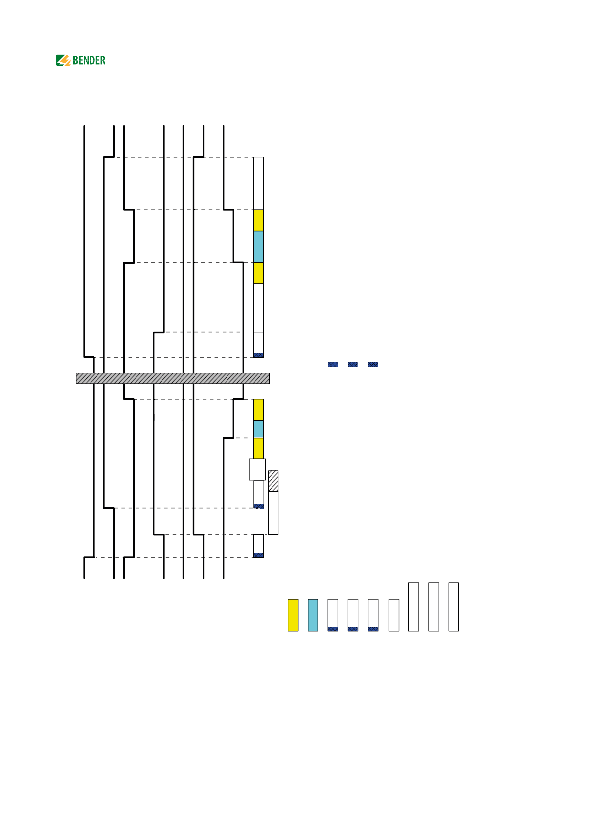
3.5.1.3 Time diagram: Changeover to generator mode
Note: Times are not shown to scale.
System description
Switching back to Line 1
(normal operation with delay on release)
1
0
t(GenOff)
t(Imp)
t(0)
t(Imp)
t(2->1)
1
t(off)
: Measuring time: approx. 50 ms
: Measuring time: approx. 50 ms
2
t(Imp)
t(0)
t(Imp)
t(Gen
Start)
1
t(off)
Generator mode
Voltage
Line 1
20
Voltage
Line 2
Voltage
Output
ATICS
Alarm failure
Alarm failure
Line 1
Line 2
t(GenMax)
1
t(on)
10
102
Generator
start relay
Switch
position
Time
delay
: Pulse time: 15 … 30 ms
t(Imp)
: Response delay ALARM failure voltage Line 1
: Delay on release ALARM failure voltage Line 1
: Delay on release ALARM failure voltage Line 2 : Measuring time: approx. 50 ms
1
t(off)
2
t(off)
1
t(0) : Dead time
t(on)
: Generator start-up delay, delayed changeover to generator.
t(GenStart)
t(2->1) : Return transfer delay time
ATICS-DIO_D00080_02_M_XXEN/08.2017
Measurements beyond "Voltage Line 2" ok.
t(GenOff) : Generator disconnecting delay time, delayed switching-off of the generator.
t(GenMax) : Generator start-up time. Monitoring the generator start-up.
Page 21
System description
WARNING
3.5.2 Monitoring the device functions
The control circuits are designed in such a way that, even though it is almost certain that a particular
fault will occur, it cannot cause the power supply at the output of the automatic transfer switching
device to fail.
ATICS® tests the switch position of the switch as well as coils 1 and 2 of the switch once a day at 12:00
p.m.
ATICS® also continuously monitors:
Power supplies 1 and 2, which supply the electronics from the systems concerned
Internal microcontrollers and memory modules
Important connecting wires, such as the measuring current transformer connection
For alarm and test combinations and alarm indicator and operator panels, device failure moni-
toring can also be programmed via the BMS bus (necessary for functional safety).
For systems with generator: total power failure possible
If the preferred line fails, ATICS® will start the generator connected to the redundant line. If the generator does not start, the line downstream of the transfer
switching device will be dead.
When the generator is switched off, ATICS® cannot check the redundant line.
Therefore, regularly test the generator and the transfer switching device to make
sure they are working properly (see checklist in the appendix to this manual).
3.5.3 Power supply
The coils of the switching device are each supplied from the line which is not currently switched on.
This ensures that it is possible to switch to the redundant line if the preferred line fails, for example.
The power supply of the electronic system is of redundant supply from lines 1 and 2. This ensures
constant supply to the electronic system even when one line fails.
If both lines fail, the changeover switch remains in the last switch position. Switch ATICS® to position
"0" using an Allen key. When power is restored, ATICS® switches on the supply again with the set delay time t(start). If several ATICS® are installed in one system, they can be switched to the preferred
line one by one starting from switch position "0" on voltage recovery. This prevents the peak loads
that would occur if the lines of several transfer switching devices were switched on simultaneously.
3.5.4 Manual mode
In manual mode, changeover can be achieved using an Allen key. The switching device can be held
in switch position "0" and locked with a padlock.
ATICS-DIO_D00080_02_M_XXEN/08.2017
21
Page 22
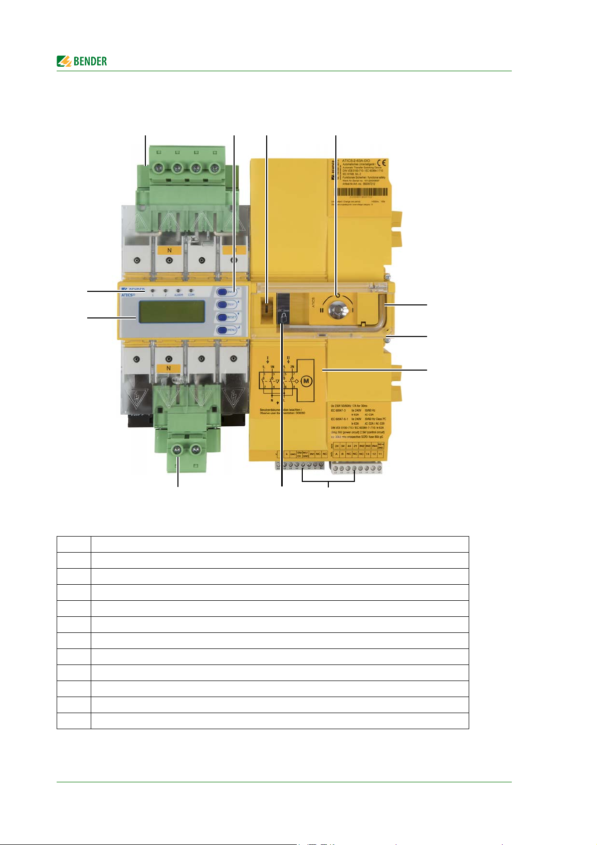
3.6 ATICS-2-DIO front view
14
5
6
8
32
12
11
10 9
7
System description
Legend
1 Green plug connector for line 1 and line 2
2 Control buttons
3 Inspection window for switch position
4 Manual mode of the transfer switching device, indicates the switch position
5 Allen key for manual mode
6 Transparent cover for changeover switch (manual mode), sealable
7 Wiring diagram for lines 1, 2 and 3
8 Three coded connector plugs
9 Locking device for switch position 0
10 Green plug connector for line 3
11 LCD
12 Operating and alarm LEDs
22
ATICS-DIO_D00080_02_M_XXEN/08.2017
Page 23
System description
15
6
7
9
43
14
11 10
8
13 12
2
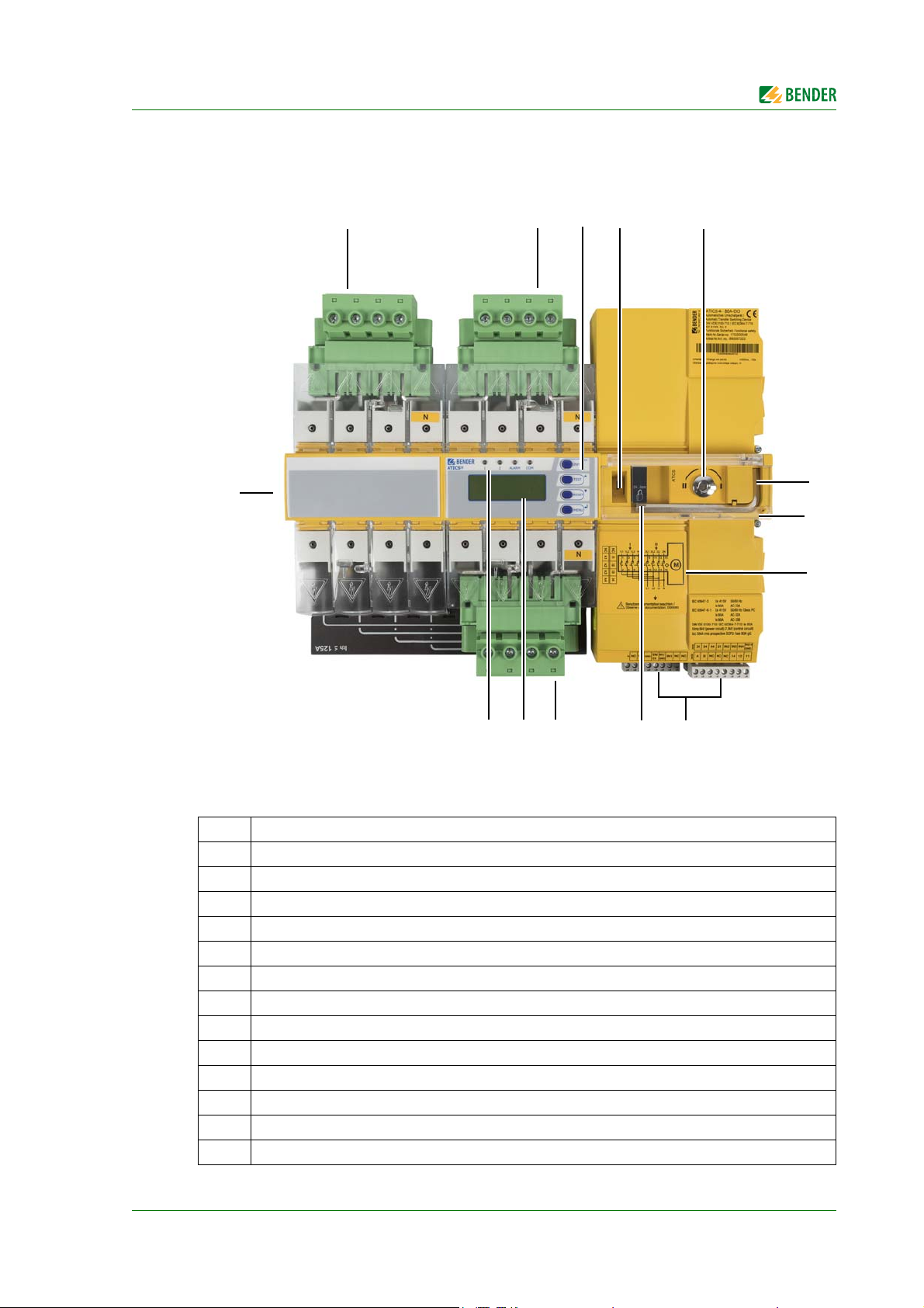
3.7 ATICS-4-DIO front view
Legend
1 Green plug connector for line 1
2 Green plug connector for line 2
3 Control buttons
4 Inspection window for switch position
5 Manual mode of the transfer switching device, indicates the switch position
6 Allen key for manual mode
7 Transparent cover for changeover switch (manual mode), sealable
8 Wiring diagram for lines 1, 2 and 3
9 Three coded connector plugs
10 Locking device for switch position 0
11 Green plug connector for line 3
12 LCD
13 Operating and alarm LEDs
14 Connector plug for measuring current transformer
ATICS-DIO_D00080_02_M_XXEN/08.2017
23
Page 24

System description
24
ATICS-DIO_D00080_02_M_XXEN/08.2017
Page 25
4. Installation and connection
DANGER
CAUTION
Risk of electrocution due to electric shock!
Touching live parts of the system carries the risk of electric shock. Before fitting
the device and prior to working on the device connections, make sure that the
power supply has been disconnected. Observe the rules for working on electrical
installations.
In manual mode, ATICS® can be held in switch position "0" and locked with a
padlock.
Disturbance due to loud switching noise
Install ATICS® in a closed electrical operating area or in a sound-proof distribution board.
4.1 Mounting
Risk of destruction by plastering
Liquid plaster may run into the device and the device may jam.
Do not seal the device with plaster.
ATICS® is suitable for DIN rail mounting or screw mounting on plate. To guarantee the protection
against accidental contact, it is to be installed behind a plastic cover.
ATICS-DIO_D00080_02_M_XXEN/08.2017
25
Page 26
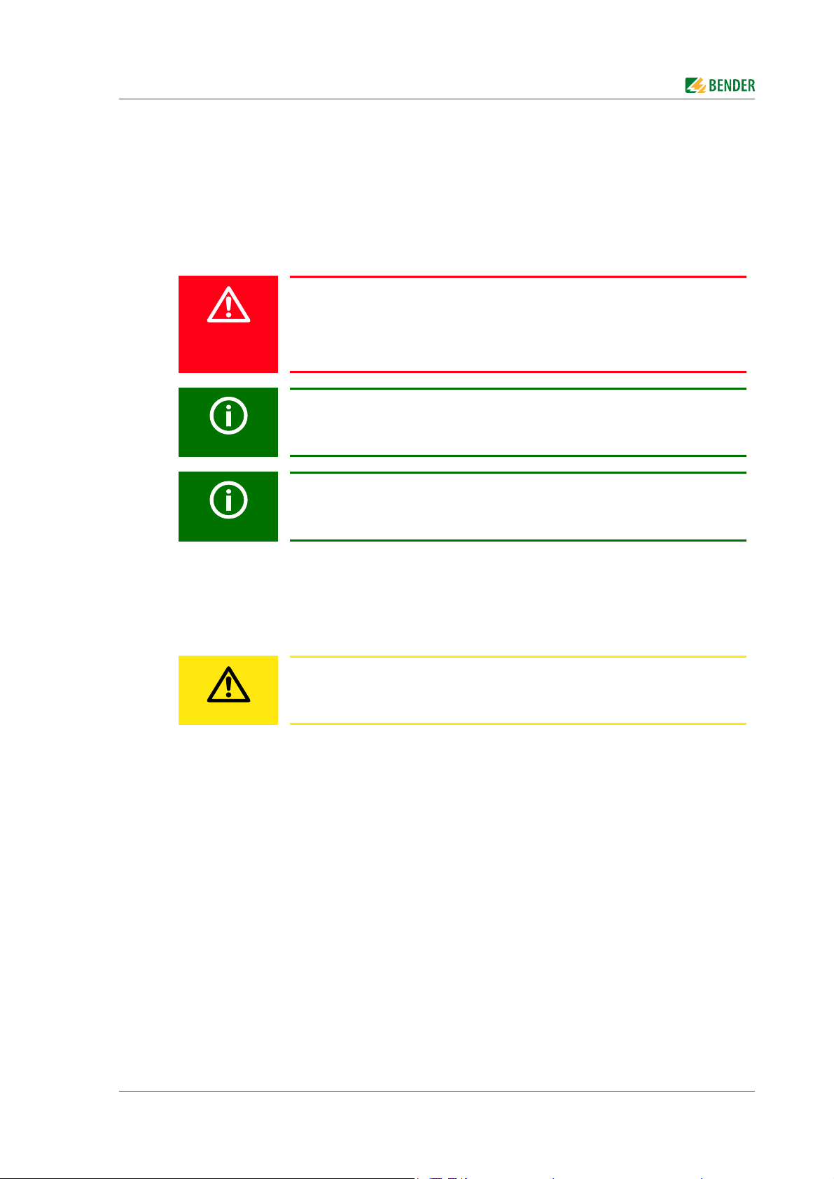
4.1.1 ATICS-2-DIO dimension diagram
*
**
***
***
340
115,3
17610452
14,7
324
263
132
23
15
132
245
M5
18
46
73,5
53
45
326
47
*
**
***
***
****
***
*****
234
52
176
115,3
14,7
M5
Installation and connection
263
132
220
222
18
47
132
245
46
52
73,5
45
* Only when using the bypass switch ATICS-BP-…: additional space required for auxiliary contact
** Adjust the cutout to the terminal cover
*** Dimensions for screw mounting on mounting plate
4.1.2 ATICS-4-DIO dimension diagram
* Only when using the bypass switch ATICS-BP-…: additional space required for auxiliary contact
** Adjust the cutout to the terminal cover
*** Dimensions for screw mounting on mounting plate
**** Additional space required for the connector plug of the measuring current transformer
***** 80 A/125 A version. 160 A version without plug connector.
26
ATICS-DIO_D00080_02_M_XXEN/08.2017
Page 27
Installation and connection
B
A
B
A
C
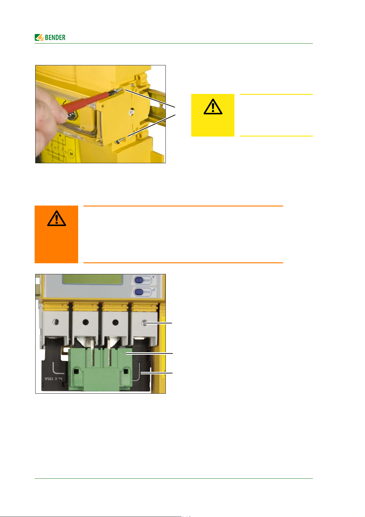
4.1.3 Removing the terminal covers
1. Push back the locking hook (B) in the
middle of the top and bottom terminal
cover (A) using a screwdriver.
2. Remove the terminal cover.
4.1.4 Mounting on DIN rail
Photo shows ATICS-2-DIO.
The description also applies to ATICS-4-DIO.
1. Place ATICS® on the top edge of the rail.
2. ATICS-2-DIO: Use a screwdriver to pull
down the lower yellow slide lock (C) and
snap ATICS® into place with slight pressure.
ATICS-4-DIO: Remove lower green plug
connector. Use a screwdriver to pull
down the two lower yellow slide lock (C)
and snap ATICS® into place with slight
pressure.
Check that the slide locks are properly
snapped into position by pulling slightly
the lower part of the enclosure.
3. Secure all terminals including the unused
terminals with Allen screws.
Tightening torque: 5 Nm.
4. Fasten the terminal covers.
ATICS-DIO_D00080_02_M_XXEN/08.2017
27
Page 28
4.1.5 Screw mounting on plate
D
If the screws are not tightened, the vibration occurring during the switching
process may damage
ATICS®.
CAUTION
WARNING
D
E
C
Provide for sufficient clearance to live conductors (voltage clearance) by using
mounting screws with flat screw heads and flat washers.
If mounted on electrically conductive material: the mounting plate has to be
earthed and the area under the terminals has to be covered with insulating material.
It is the responsibility of the mounting staff to select the appropriate mounting
plate and mounting screws and to keep the prescribed torque setting.
Installation and connection
5. Always tighten the mounting screws (D)
(PZ1, 8,8 lb-in, 1 Nm).
The photo shows ATICS-2-DIO.
The description also applies to ATICS-4-DIO.
1. Undo the Allen screws of the terminals
(C).
2. Remove the green plug connectors (D)
top and bottom.
3. Remove the black bridge (E) bottom.
4. Fasten ATICS® to the mounting plate with
M5 mounting screws, torque setting 22
lb-in, 2.5 Nm (see "ATICS-2-DIO dimension diagram").
5. Insert the black bridge (E), bottom.
6. Plug in the green plug connectors (D) top
and bottom.
7. Use Allen screws to tighten all terminals
(C) including the unused terminals.
Tightening torque: 5 Nm.
8. Fasten the terminal covers.
28
ATICS-DIO_D00080_02_M_XXEN/08.2017
Page 29

Installation and connection
4.2 Connection
4.2.1 Short-circuit protection
The choice of back-up fuses F should ensure both short-circuit protection for the transformer and selectivity for the overcurrent devices connected downstream in the IT systems.
The connecting wires between the automatic transfer switching devices and the overcurrent protective device downstream are to be laid so that they are short-circuit and earth-fault proof.
When choosing back-up fuses, keep to both the maximum permissible values laid down by the
guidelines which apply to the site of use and national and international standards to make sure that
the contacts do not weld.
For recommendations on the use of the appropriate fuse, refer to the nameplate of ATICS® and to
the ordering details in this manual.
ATICS-DIO_D00080_02_M_XXEN/08.2017
29
Page 30
4.2.2 Connecting ATICS® safely
DANGER
DANGER
WARNING
WARNING
WARNING
Risk of fatal injury from electric shock
If any of the supplies are switched on, some of the parts of the system which are
not yet fully installed may be live.
Open the transparent cover of the
device for manual mode selection and
wait until the display shows "Manual
mode".
Turn the Allen key to switch position "0".
Leave the transparent cover open and
lock the transfer switching device with a
padlock to prevent it from starting accidentally.
Installation and connection
Risk of fatal injury from electric shock
Connecting wires can come loose and fall out if the ferrules being used are too
short, the wire ends are tinned or the connection screws have not been tightened
enough.
Consider a stripping length of 20 mm and do not use ferrules when connecting
lines 1, 2 and 3.
Note the assignment of the terminals. Note especially that the two supplies are
always connected to the device from the top.
Use a torque wrench to tighten the terminal screws.
Check all the screws on a regular basis to make sure they are seated tightly.
Risk of destruction when insulation and voltage test are carried out
-> Disconnect the device from the mains for the duration of the test.
Risk of destruction in the event of phase failure in three-phase systems
If only one of the phases fails, it may result in overvoltages which can damage
the connected devices.
-> Install a device for all-pole disconnection in the event of phase failure.
Risk of destruction if connected incorrectly
-> The terminals labelled GND must not be connected to PE.
30
ATICS-DIO_D00080_02_M_XXEN/08.2017
Page 31

Installation and connection
III
1357
2468
1L 2N2L1N
NL
lNCNC
EN/EXIN1/
GND
IN1GNDk
grau
ANC 111214NCNCB
schwarz
21 IN3IN2443424
IN2-4
GND
IN4
weiß
ATICS-2-DIO terminals
Legend
1L, 1N Connection line 1 (input line)
2L, 2N Connection line 2 (input line)
L, N Connection line 3 (output line)
l, k Connection measuring current transformer T3 (STW3) for monitoring the load
current downstream of the transfer switching device (short-circuit monitoring)
GND, En/Ex Connection must not be used. Intended for Bender-internal purposes only (12
V).
IN1/GND, IN1 Digital input, configurable (see "Settings menu 5: Digital input" on page 75)
NC Not used
24, 34, 44, 21 3 alarm relays (1 N/O contact each), 21 = common connection for the three
alarm relays
IN2, IN3, IN4, IN2-4 GND 3 digital inputs
A, B BMS bus connection
14, 12, 11 Alarm relay, programmable function
ATICS-DIO_D00080_02_M_XXEN/08.2017
31
Page 32

ATICS-4-DIO terminals
WARNING
II
9111315
10 12 14 16
2L1 2N2L32L2
ANC 111214NCNCBNC NCNC
EN/EXIN1/
GND
IN1GNDNC
I
1357
2468
1L1 1N1L31L2
grau
NC l4l3l2l1
NC k4k3k2k1
schwarz
L1 NL3L2
21 IN3IN2443424
IN2-4
GND
IN4
weiß
ATICS-4-125A-DIO and ATICS-4-160A-DIO only:
High temperatures may affect the terminals
The terminals for the connection of line 1, 2, 3 are designed for the specified rated
operational current, at room temperature.
-> Avoid higher temperatures or ensure that the load current is reduced.
Installation and connection
Legend
1L1, 1L2, 1L3, 1N Connection line 1 (input line)
2L1, 2L2, 2L3, 2N Connection line 2 (input line)
L1, L2, L3, N Connection line 3 (output line)
NC Not used
GND, En/Ex Connection must not be used. Intended for Bender-internal purposes only (12
IN1/GND, IN1 Digital input, configurable (see "Settings menu 5: Digital input" on page 75)
24, 34, 44, 21 3 alarm relays (1 N/O contact each), 21 = common connection for the three
IN2, IN3, IN4, IN2-4 GND 3 digital inputs
A, B BMS bus connection
14, 12, 11 Alarm relay, programmable function
l1, l2, l3, l4,
k1, k2, k3, k4
V).
alarm relays
Connection measuring current transformer T1 … T4 for monitoring the load
current downstream of the transfer switching device (short-circuit monitoring).
Also refer to "Connection example: ATICS-4-DIO basic configuration" on
page 34.
Note: Insert the plug until it noticeably clicks into place
32
ATICS-DIO_D00080_02_M_XXEN/08.2017
Page 33

Installation and connection
CAUTION
4.2.3 Connection example: ATICS-2-DIO basic configuration
Risk of destruction if connected incorrectly
The terminals marked "*" are intended for Bender-internal purposes only. If this
is ignored, the ATICS® transfer switching device may be damaged.
ATICS-DIO_D00080_02_M_XXEN/08.2017
33
Page 34

4.2.4 Connection example: ATICS-4-DIO basic configuration
CAUTION
Risk of destruction if connected incorrectly
The terminals marked "*" are intended for Bender-internal purposes only. If this
is ignored, the ATICS® transfer switching device may be damaged.
Installation and connection
34
ATICS-DIO_D00080_02_M_XXEN/08.2017
Page 35

Installation and connection
CAUTION
4.2.5 Connection example: ATICS-2-DIO with bypass switch
Risk of destruction if connected incorrectly
The terminals marked "*" are intended for Bender-internal purposes only. If this
is ignored, the ATICS® transfer switching device may be damaged.
ATICS-DIO_D00080_02_M_XXEN/08.2017
35
Page 36

4.2.6 Connection example: ATICS-2-DIO with bypass switch
CAUTION
Risk of destruction if connected incorrectly
The terminals marked "*" are intended for Bender-internal purposes only. If this
is ignored, the ATICS® transfer switching device may be damaged.
Installation and connection
36
ATICS-DIO_D00080_02_M_XXEN/08.2017
Page 37

Installation and connection
4.2.7 Instructions for connection
4.2.7.1 BMS bus
Ex works, the terminals A and B are available for connecting BMS-enabled devices. Alarm indicator
and test combinations, alarm indicator and operator panels or other bus-enabled Bender devices
can be connected. The bus line must be terminated at both ends with resistors (120 Ω, 0.25 W).
Please note the information in the "BMS bus" manual.
4.2.7.2 MK… alarm indicator and test combination and TM… alarm indicator and operator
panels
MK2430, MK800 and TM800 are used. They have the following capabilities:
Displaying messages of the ATICS® transfer switching device
Mutual monitoring for failure
4.2.7.3 SCADA systems (Supervisory Control and Data Acquisition)
If messages from the ATICS® transfer swit ching d evice a re to be forwarded to a SCADA system, the following possibilities exist:
Protocol converters (gateways, e.g. COM465…)
Common alarm via the ATICS® relay output
Alarms via interconnected signal converters SMO480-12 or SMO482-12.
TM800, SMO480-12 and SMO482-12 convert serial signals from Bender devices into potentialfree relay contact alarms.
4.2.7.4 Bypass switch (optional)
The ATICS-BP-… bypass switch makes it possible to test and change the two-pole ATICS® transfer
switching device without interrupting the power supply to the line downstream of the transfer
switching device. Adjusting the settings: see "Operation with bypass switch" on page 92.
ATICS-DIO_D00080_02_M_XXEN/08.2017
37
Page 38

Installation and connection
AB
C
D
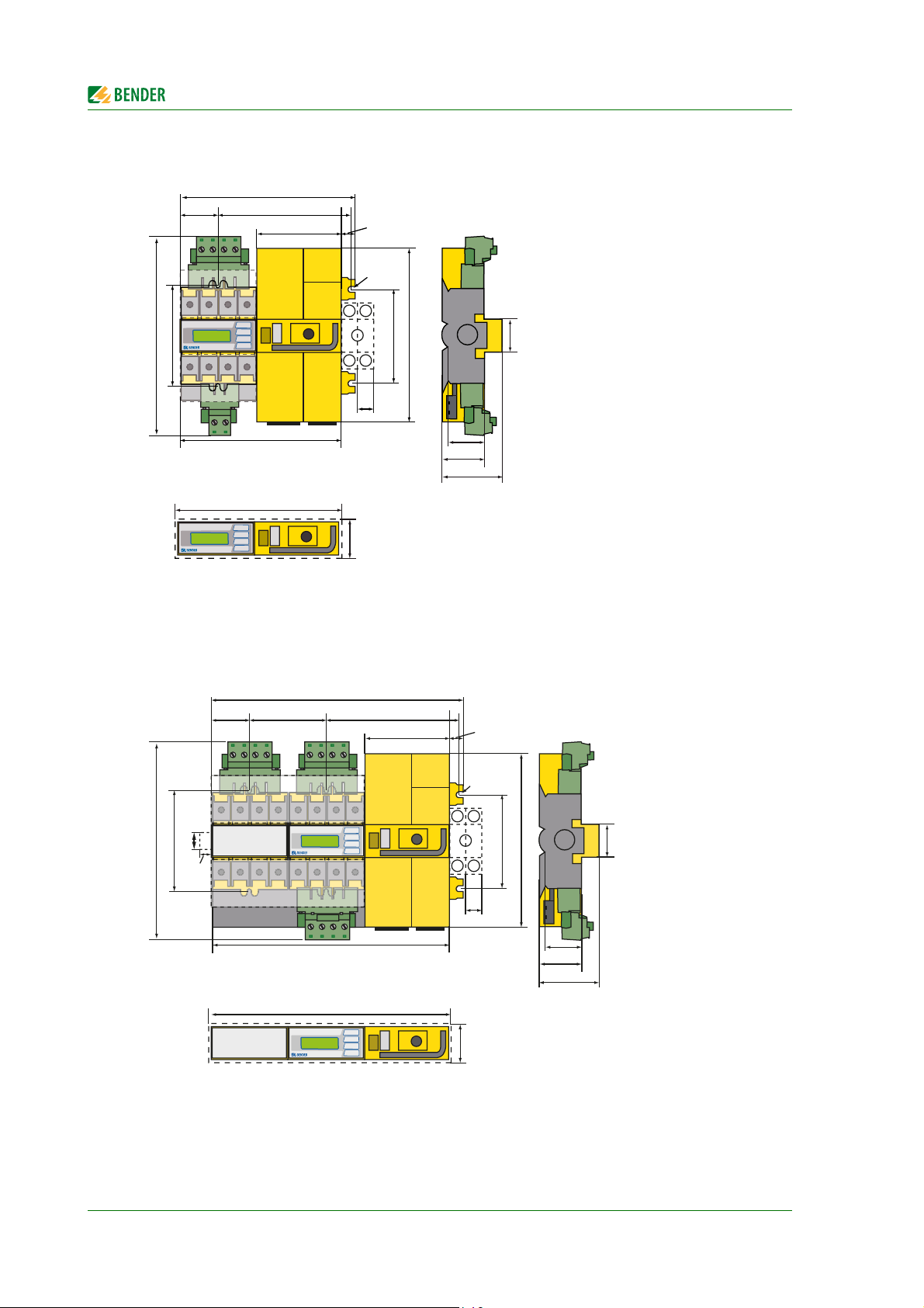
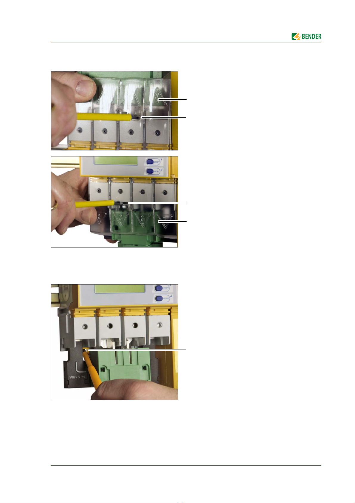
4.2.8 Fastening, inserting and securing connections
Connect the terminals to the plug connectors (A, B) and the connector plugs (C, D) according to the
wiring diagram.
Connect the lines 1, 2 and 3 to the plug connectors (A, B). Consider a stripping length of 20 mm
and do not use ferrules. Use a Torx® screwdriver T20 or a slotted screwdriver of 6.5 x 1.2 mm.
Tightening torque: 2.5 Nm (≤ 25 mm²) or 4.5 Nm (≥ 25 mm²).
Connect the three connector plugs (C) with a slotted screwdriver of 2.5 x 0.4 mm. Stripping
length: 7 mm. Tightening torque: 0.22…0.25 Nm.
Insert bottom green plug connector
(B) and secure with mounting screws.
AT IC S - 2- D I O: After that, insert top
green plug connector (A) and secure
with mounting screws.
AT IC S - 4- D I O: Only then insert the
two top green connector plugs and
secure them with mounting screws.
Insert the three connector plugs (C).
ATICS -4- D IO o n l y:
Insert the connector plug (D) of the
measuring current transformers
T1…T4 (D).
Note:
The plug must noticeably click into
place!
38
ATICS-DIO_D00080_02_M_XXEN/08.2017
Page 39

Installation and connection
CAUTION
4.3 Other functions
4.3.1 Sealing the transparent cover of the transfer switching device
4.3.2 Manual mode
The transparent cover can only be sealed
when it is closed (automatic mode).
Risk of injury from rotating Allen key
When the transparent cover is closed, ATICS® is in automatic mode. ATICS® detects this by means of the button being pressed under the transparent cover.
When the transparent cover is opened, the button is no longer pressed and ATICS® switches to manual mode.
When the transparent cover is open, make sure that this button is not pressed accidentally. Check and make sure that the message "Manual mode" appears on
the display. Only then can the Allen key be used to set the changeover switch to
manual mode.
Manual mode can be enabled in the following ways:
Open the transparent cover
Set the digital input. "M/A" function
must be set (see "Settings menu 5:
Digital input" on page 75).
Manual mode:
Put the handle on the Allen key
Use the Allen key to change over
The switching device can be held in
switch position "0" and locked with a
padlock.
ATICS-DIO_D00080_02_M_XXEN/08.2017
39
Page 40

Installation and connection
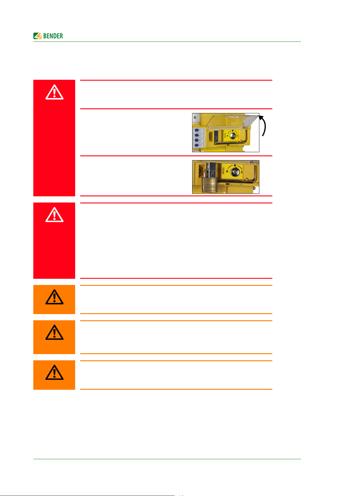
4.3.3 Locking the transfer switching device with a padlock
It is only possible to lock the selector switch in manual mode (transparent cover open). The locking
device can only be locked in switch position "0".
Padlock shackle diameter: 4 mm … 8 mm (3/16” … 5/16”)
Locking the transfer switching device:
1. Pull out locking device
2. Thread in padlock and close it
The switch position cannot be changed until the lock has been removed and the locking device has
been pushed in.
40
ATICS-DIO_D00080_02_M_XXEN/08.2017
Page 41

5. Commissioning, settings and testing
CAUTION
CAUTION
5.1 Design and installation
Risk of missing or false messages on the display on MK..., TM... or FTC...
MK… alarm indicator and test combinations, TM... alarm indicator and operator panels or BMS Ethernet gateways COM465…, which, together with ATICS®,
are connected to a BMS bus must be loaded with the latest operating software
(e.g. MK800/TM800/MK2430 V 4.03 or higher).
Older MK…, TM… or FTC… cannot interpret the alarms of ATICS® because the
text modules required for ATICS® are not integrated yet. These devices must either be updated or replaced.
The TMK-SET configuration software must also be the latest version.
Risk that ATICS® does not switch
ATICS® requires enough current (2 pulses of 17 A for 30 ms) for a changeover. If
there are several ATICS® in one system it is possible that the current is insufficient,
especially when feeding from a battery-powered power supply.
Set the delay time t(start) on the devices in such a way that after voltage recovery
the devices switch to the preferred supply one by one.
Observe the relevant standards and regulations for installation and connection as well as the
operating manual of the respective device.
Provide at least two places for MK… alarm indicator and test combinations or TM… alarm indi-
cator and operator panels. These panels display messages from the ATICS® automatic transfer
switching device and monitor each other for failure. This is an essential part of the safety
concept (functional safety, SIL2).
Application examples of MK… or TM… in hospitals:
– Medical locations
– Continuously manned area (e.g. nurses' station)
– Technical area
Provide a fail-safe power supply for the MK… or the TM…
The TM... and MK... for the medical and technical area must be supplied with power from differ-
ent lines and sources.
Example:
The MK… or the TM… in medical locations is supplied from line 3 of the transfer switching
device. The MK… in technical areas is supplied from a fail-safe line backed up by battery.
ATICS-DIO_D00080_02_M_XXEN/08.2017
41
Page 42

Commissioning, settings and testing
5.1.1 Configure MK… or TM…
Configure MK… or TM… in a meaningful way
In addition to the alarm, also configure a brief message of what to do or who to
notify. Examples:
- Failure line 1. Call building services Tel. -123.
MK… or TM… must display at least the following faults detected by ATICS®:
Failure line 1, failure line 2
Device error, device failure ATICS®
Failure of the other MK… or TM…
Device error with complete text or error code
5.1.2 ATICS-2-DIO: Messages on the BMS bus (channel use)
BMS
chan
nel
Entry in the menu
1.Alarm/meas.
Description
values
1 1. Line 1: 228V Line 1 Voltage Voltage* ---
2 2. Line 2: 183V Line 2 Voltage Voltage* ---
3 3. Position:1 Switch position 0, 1, 2 --- ---
4 4. t(2->1):--
or
SwitchBackLock
5 5. Automatic mode Manual/Automatic
6 6. Status Device error --- Error code (see
7 7. I(3):35A Load current
8 8. Digital input: Digital input 1 - - ** Alarm text** ---
9 9. Digital input: Digital input 2 - - ** Alarm text** ---
10 10. Digital input: Digital input 3 - - ** Alarm text** ---
11 11. Digital input: Digital input 4 - - ** Alarm text** ---
12 without function
Return transfer
delay time is
enabled, counting
backwards or
switching back
interlocking
function
mode
TN system
Operational
status
message
Seconds --- ---
--- Manual
Current Current Connect. fault
Alarm
message
mode
Error
---
chapter "8.1.2 ")
CT
* Message dependent on the parameter assignment in the "Settings menu 1: Changeover" -> "System" (for
details see "Settings menu 1: Changeover" on page 69)
** Message dependent on the input parameter assignment (for details see "Messages for alarm on the
digital input" on page 44)
42
ATICS-DIO_D00080_02_M_XXEN/08.2017
Page 43

Commissioning, settings and testing
5.1.3 ATICS-4-DIO: Messages on the BMS bus (channel use)
BMS
chan
nel
Entry in the menu
1.Alarm/meas.
Description
values
1 1. Line 1: 228V Line 1 Voltage Voltage* Phase sequence
2 2. Line 2: 183V Line 2 Voltage Voltage* Phase sequence
3 3. Position:1 Switch position 0, 1, 2 --- ---
4 4. t(2->1):--
or
SwitchBackLock
5 5. Automatic mode Manual/Automatic
6 6. Status Device error --- Error code (see
7 7. I(3):35A Load current on the
8 8. I(3):35A Load current on the
9 9. I(3):35A Load current on the
10 10. I(3):35A Load current in the
11 11. Digital input: Digital input 1 - - ** Alarm
12 12. Digital input: Digital input 2…4
Return transfer
delay time is
enabled, counting
backwards or
switching back
interlocking
function
mode
TN system on phase
L1
TN system on phase
L2
TN system on phase
L3
TN system on neutral conductor
(common alarm)
Operation
al
status
Alarm
message
Error
message
left,
unbalance
left,
unbalance
Seconds --- ---
--- Manual
mode
Current Current Connect. fault CT
Current Current Connect. fault CT
Current Current Connect. fault CT
Current Current Connect. fault CT
text**
- - ** Alarm
text**
---
chapter "8.1.2 ")
---
---
* Message dependent on the parameter assignment in the "Settings menu 1: Changeover" -> "System" (for
details see "Settings menu 1: Changeover" on page 69)
** Message dependent on the input parameter assignment (for details see "Messages for alarm on the
digital input" on page 44)
ATICS-DIO_D00080_02_M_XXEN/08.2017
43
Page 44

Commissioning, settings and testing
Messages for alarm on the digital input
The following operational status and alarm messages may appear depending on the settings in the
"Settings menu 5: Digital input":
Menu
setting
off Digital input switched off No alarm -
M/A Enabling manual mode Alarm "Manual mode" 5
Bypass Bypass enabled Alarm "Manual mode" 5
no2->1 Enable switching back interlocking
1<->2 Change preferred line No alarm
TEST TEST- carry out changeover No alarm
ALARM ATICS-2-DIO:
ALARM ATICS-4-DIO:
Function of digital input Alarm on BMS bus BMS channel
Operational status mes-
function
Convert message at digital inputs 1…4
into alarms on the BMS bus
Convert message at digital inputs 1…4
into alarms on the BMS bus.
Channel 11 = DigIn 1
Channel 12 = Common alarm DigIn
2…4
The common alarm code corresponds
to the first message, which has triggered the common alarm.
sage "Switch-back lock"
Alarm "Digital input" 8, 9, 10, 11
Alarm "Digital input" 11, 12
4
5.1.4 Tests, decommissioning
Abide by the relevant local or national regulations for periodic verifications on electrical instal-
lations.
If you notice changes on ATICS®, you must immediately start checking the transfer switching
device.
Heed the alarms on the transfer switching device. ATICS® reports in good time when testing or servicing is necessary or if safe operation of the device according to IEC 61508 is no longer guaranteed
(e.g. due to component failure) and action must be taken.
44
ATICS-DIO_D00080_02_M_XXEN/08.2017
Page 45

Commissioning, settings and testing
5.2 Setting and testing according to the checklist
The settings made at the factory take into account a total changeover period t ≤ 0.5 s and switching
back to the preferred supply within 10 seconds on voltage recovery.
The response delay t(on), the dead time t(0), the delay on release t(off) and the return transfer delay
time t(2->1) of ATICS® are configurable and must be adjusted to the requirements of the specific application case and the requirements of DIN VDE 0100-710 (VDE 0100 Part 710) for automatic changeover devices. If the current monitoring (short-circuit detection) is deactivated in the menu "Settings"
> "Current", an additional short-circuit current calculation and configuration of the response time
t(on) is required.
The total turn-off time (from the point at which the fault occurs until the arc in the overcurrent
protective device is cleared) must be less than the minimum delay for the changeover of the
automatic transfer switching device.
Setting: Response delay t(on)
If several automatic transfer switching devices are connected in series in a power supply sys-
tem, it is recommended that they are time-graded.
Setting: Response delay t(on), return transfer delay time t(2->1) and delay on release t(off).
As part of the response delay (to be custom-set), you must, at the very least, take into account
the periods of time when the circuit experiences short interruptions, and the response times of
the short-circuit protection equipment upstream or downstream. Regardless of this, a switchover pause corresponding to the installation location should be taken into account, in order to
avoid switching overvoltages.
Setting: Response delay t(on), dead time t(0) and return transfer delay time t(2->1).
The factory settings and system-specific settings of the ATICS® DIO transfer switching device are
documented on the checklist. Please carry out all the work outlined in the list and log each test step.
Keep the checklist with this manual near to the device.
ATICS-DIO_D00080_02_M_XXEN/08.2017
45
Page 46

Commissioning, settings and testing
5.3 Addressing example
Insert terminating resistors correctly
Communication via the BMS bus is only guaranteed when there is a terminating
resistor at the beginning and at the end of the BMS bus. Other terminating resistors cause malfunctions and must not be used. Please note the information in
the "BMS bus" manual.
An automatic transfer switching device with two MK…
Device Parameter Address settings for an automatic transfer switching device
AT IC S ®
MK…
MK…
Bus address 3
Address 1
Alarm address 3, 2*
Address 2
Alarm address 3, 1*
* These alarm addresses are used for MK… or TM… to monitor one another for device failure
46
ATICS-DIO_D00080_02_M_XXEN/08.2017
Page 47

6. Operation
1 2 ALARM COM
21345
6
7
8
9
This chapter can also be used as a quick reference guide by technical operating personnel.
6.1 Operating and display elements
LED and LCD
1 Illuminated graphic LCD
2 LED "1" lights up when line 1 is ready
3 LED "2" lights up when line 2 is ready
4 LED "Alarm" lights up when there is an alarm message
5 LED "COM" flashes during communication via the BMS bus
The buttons have the following functions:
6 "INFO" Calls up standard information
7 "TEST" Calls up test menu
8 "RESET" Resets alarm and fault messages, unlocks switching back interlocking function
9 "MENU" Toggles between the standard display, alarm display and "MENU"
ESC Exits the menu function without changing parameters
Parameter changes, scrolling
Parameter changes, scrolling
↵ Confirms parameter changes (Enter button)
ATICS-DIO_D00080_02_M_XXEN/08.2017
47
Page 48

6.2 Quick reference guide
228V
50.0Hz
1 0 2 231V
50.0Hz
14:11
12.10.2010
1423
6.2.1 ATICS-2-DIO: Display under normal operating conditions
There is no alarm message. The LCD shows the standard information.
Example:
Legend
Operation
1 Line 1: Measured values of mains voltage and frequency
2 Switch position of the transfer switching device
3 Date and time
4 Line 2: Measured values of mains voltage and frequency
The device shows the alarm status for each measured value
No alarm
Alarm
Alternative displays in the bottom line of the display
The device displays alarm messages in the bottom line of the display. Also shown there are:
- Switching back interlocking function
- Manual mode
- Countdown timer for return transfer time
48
ATICS-DIO_D00080_02_M_XXEN/08.2017
Page 49

Operation
231V
230V
229V
50.0Hz
229V
228V
227V
1 0 2
14:11
12.10.2010
132
50.0Hz
4
6.2.2 ATICS-4-DIO: Display under normal operating conditions
There is no alarm message. The LCD shows the standard information.
Example:
Legend
1 Line 1: Measured values of mains voltage and frequency
2 Switch position of the transfer switching device
3 Date and time
4 Line 2: Measured values of mains voltage and frequency
The device shows the alarm status for each measured value
No alarm
Alarm
Alternative displays in the bottom line of the display
The device displays alarm messages in the bottom line of the display. Also shown there are:
- Switching back interlocking function
- Manual mode
- Countdown timer for return transfer time
ATICS-DIO_D00080_02_M_XXEN/08.2017
49
Page 50

6.2.3 Display during fault condition
228V
50.0Hz
1 0 2
0.00V
0.00Hz
14:11
Undervoltage
228V
228V
1 0 2
0.00V
0.00V
228V
14:11
0.00V
Undervoltage
ATICS-2-DIO
ATICS-4-DIO
ALARM xx/yy
Undervoltage
0V
Addr.:3 Chan.:2
There is an alarm message.
The yellow "Alarm" LED lights up.
A detailed message appears on the LC display.
Example: Line 2 has no voltage
Press the button "↵" to display the current alarm.
Operation
– Line 1: ALARM
xx = Serial number of the displayed alarm
yy = Number of pending messages
Use the arrow buttons ", " to select the previous or next message.
– Line 2: Alarm status and alarm text
– Line 3: Measured value
– Line 4: Address and channel of the device triggering the message
If no button is pressed for a few seconds, the standard display reappears.
The alarm text displayed in case of failure of one line depends on the setting "System" in the "Settings menu 1: Changeover" on page 69.
If individual alarm messages are programmed on a TM… alarm indicator and
operator panel or on an MK... alarm indicator and test combination, the display
of this device may differ from the display of ATICS®.
Press "↵" again, then the main menu will appear.
50
ATICS-DIO_D00080_02_M_XXEN/08.2017
Page 51

Operation
Exit
1.Autom. changeover
2.Manual changeover
3.Last switch
TEST
Enter password:
0 0 0
6.2.4 Test function
A test is used to test the functioning of the device. There are several ways to call up a test menu:
Select standard display and then press the "TEST" button on the front panel of the device for at
least one second
Call up "TEST" mode in the Control menu
A test of the changeover function can also be triggered via a digital input (function similar to "Manual
changeover"). Test menu:
Select:
Menu item Function Page
1. Autom. changeover Test of the changeover function. Switches back automatically after
time t(test).
2. Manual changeover Test of the changeover function. Switches back after pressing the
"RESET" button.
3. Last switch Save last changeover as test 54
4. Generator Start generator without changing over. Terminate test by pressing
the "RESET" button.
5. Test communication Test communication via the BMS bus. To do this, simulate an alarm
and send an alarm message via the BMS bus.
52
53
55
56
Test menus 2…4 are protected by a password (see Settings-> Password -> Test).
Password protection is only effective if the password has been enabled (switched
on). When an attempt is made to open one of these menus, the password entry
screen appears automatically:
During an "Autom. changeover" test or "Manual changeover" test, changeover
does not take place until a delay time has elapsed, which is indicated by the
progress bar.
For technical reasons the menu items "Control> Test > Manual changeover"
"Control > Test >Generator" and "Control > Test > Communication" cannot be
accessed via a gateway (COM465…, CP700, …).
ATICS-DIO_D00080_02_M_XXEN/08.2017
51
Page 52

If manual mode is selected for changeover (transparent cover open or digital in-
Info
TEST
Cancel
Autom. changeover
Cancel
Autom. changeover
TEST
t(1->2):
457ms
t(test):
10s
Quit: RESET
put set to "manual changeover") then no changeover can take place under the
test menu "Autom. changeover" or "Manual changeover". ATICS® then displays
the following fault alarm:
To run a test, the transfer switching device must be in automatic mode.
During an "Autom. changeover" or "Manual changeover" test, the changeover
period t(1->2) is displayed. This is the time required for changing over from the
preferred line to the redundant line. This time may differ from the return transfer
time! Also refer to "Time diagram: Changeover between the preferred and the redundant line" on page 18
Operation
6.2.4.1 Test menu 1: Autom. changeover
Autom. changeover Test of the changeover function. The device changes to the redundant line.
The changeover period t(1->2) is displayed. After the set time t(test) has
elapsed, the device changes back to the preferred line.
Cancel Back to test menu
The date of the test is saved in the test data logger to remember the next test once the test interval
has elapsed. The messages from this test are also stored in the history memory.
52
ATICS-DIO_D00080_02_M_XXEN/08.2017
Page 53

Operation
Manual changeover
Cancel
Manual changeover
TEST
t(1->2):
346ms
t(test):
--
Quit: RESET
CAUTION
6.2.4.2 Test menu 2: Manual changeover
Manual changeover Test of the changeover function. The device changes to the redundant line
and remains in this switch position. The changeover period t(1->2) is displayed. The device does not change back to the preferred line until the "RESET" button has been pressed.
Cancel Back to test menu
The date of the test is saved in the test data logger to remember the next test once the test interval
has elapsed. The messages from this test are also stored in the history memory.
Risk that the test is accidentally not terminated
If the test menu 3: "Manual changeover" is left after changing over to the redundant line, then ATICS® remains in this switch position and in "TEST" mode.
- Wait until "Quit: RESET" appears on the display.
- Press the "RESET" button.
- Check whether ATICS® has changed to the preferred line.
Manual mode aborts manual test
When the transparent cover is opened after changing over to the redundant line,
ATICS® switches to manual mode. The test will be aborted.
After closing the transparent cover, ATICS® switches back to the preferred line.
No entry will be made in the test data logger.
ATICS-DIO_D00080_02_M_XXEN/08.2017
53
Page 54

6.2.4.3 Test menu 3: Last switch
Last switch
1.Date: 20.09.11
2.TEST: 02.03.11
Save
Save
Cancel
Save
Last switch
1.Date: 20.09.11
2.TEST: 21.03.11
Save
If ATICS® has changed over due to a failure or a planned shutdown of the preferred line, then the last
switching operation can be saved as a test.
1. Date Date of the last changeover
2. Test Date on which the next test is due
Overwrite Date of last changeover is saved as a test date
1. Save Saves the date of last changeover as the test date, as long as that date is later
than the previous entry.
2. Cancel Back to test menu "Last switch"
After saving, the date on which the next test is due is counted up by the test interval (in this case, 6
months).
Operation
The date of the test is saved in the test data logger to remember the next test once the test interval
has elapsed. A changeover period is not saved. The messages from this test are also stored in the history memory.
54
ATICS-DIO_D00080_02_M_XXEN/08.2017
Page 55

Operation
Generator
Cancel
Generator
TEST
t(1->2):
8s
t(test):
--
Quit: RESET
WARNING
6.2.4.4 Test menu 4: Generator
Executing this function makes sense only when a generator is connected to the
redundant line and the associated settings have been carried out (see "Settings
menu 1: Changeover" on page 69). To avoid voltage interruptions, in the test
menu "Generator", ATICS® does not switch to the redundant line.
In order to test the generator and the changeover switch, select "Autom. changeover" or "Manual changeover".
Generator Generator start relay is switched. The generator starts. However, there is no
changeover to the redundant line. The test is not terminated and the generator turned off again until the "RESET" button has been pressed. The
progress of the test is shown on the display.
Cancel Back to test menu
The messages from this test are also stored in the history memory. The date of the test is saved to remember the next test once the test interval has elapsed.
Risk that the generator test is accidentally not completed
If the test menu 5: "Generator" is left after the generator has started, then ATICS®
remains in this switch position and in "TEST" mode. This means that the generator is not switched off.
- Wait until "Quit: RESET" appears on the display.
- Press the "RESET" button.
- Check whether the generator is switched off.
ATICS-DIO_D00080_02_M_XXEN/08.2017
55
Page 56

6.2.4.5 Test menu 5: Test communication
Channel disabled
Exit
Channel:--
Manual mode:--
Exit
Channel:5 Mode
Test communication via the BMS bus. In order to do this, a fault message is simulated. This alarm
message is sent to evaluator devices (e.g. alarm indicator and operator panels, MK800, SMO…).
Check that these devices are responding to the alarm message as requested. Select a channel:
1. Use the "" arrow button to go to the channel setting. Press the "↵" button.
2. Use the arrow buttons to select the channel for which the alarm message is to be simulated.
Press the "↵" button to confirm your selection.
The alarm status will change from
(no alarm) to (alarm). If the alarm status is not dis-
played, then the settings made for ATICS® will not permit simulation of this alarm.
Example of an alarm simulation: "Channel 5: MANUAL MODE" is selected.
ATICS® stays in this menu until it is exited by pressing the "ESC" button.
During this time, all the alarms on the BMS bus have the word "TEST".
Operation
Only the alarm messages listed in the following table can be simulated:
"ATICS-2-DIO: Messages on the BMS bus (channel use)" on page 42 and "ATICS4-DIO: Messages on the BMS bus (channel use)" on page 43.
56
ATICS-DIO_D00080_02_M_XXEN/08.2017
Page 57

Operation
Exit
1.Alarm
2.SwitchBackLock
3.Changeover
Delete
Cancel
Delete
6.2.5 Reset function
A RESET is used to reset the alarm and fault messages for the device and for reactivating the switching back interlocking function of the changeover switch. There are several ways to call up a test
menu:
Select standard display and then press the "RESET" button on the front panel of the device for
at least one second.
Select the "RESET" function from the Control menu. Reset menu:
Select:
Menu item Function Page
1. Alarm Resets alarm and fault messages on the device. 57
2. SwitchBackLock Reactivates the switching back interlocking function for the changeover function. The device changes back to the redundant line.
3. Changeover Change alarm value for the:
- maximum number of changeover operations performed
- maximum number of operating hours
- maximum number of changeover operations performed
which were carried out with overcurrent or short-circuit current
58
59
6.2.5.1 Reset menu 1: Alarm
Delete Resets alarm and fault messages on the device. The progress of the test is
shown on the display.
The reset is required if one or more alarm-triggering parameters are not constantly monitored so that the end of the alarm condition was not detected.
Cancel Back to reset menu
For all pending alarms, the date and time of the reset are entered in the line "End" in the history
memory. The "ALARM" LED goes out.
If the fault persists, a new entry is written in the history memory. The "ALARM" LED is still lit.
ATICS-DIO_D00080_02_M_XXEN/08.2017
57
Page 58

6.2.5.2 Reset menu 2: SwitchBackLock
Delete
Cancel
Delete
Delete Cancels the switching back interlocking function for changeover. The
progress of the test is shown on the display. The device changes back to the
redundant line.
Cancel Back to reset menu
There are different possibilities to deactivate the switching back interlocking
function via a gateway (COM4xx, CP700 etc.):
• Via menu: Select "RESET > Switch-back lock".
Requirement: Parameter setting must be possible (menu "Settings > Interface > Settings > On").
• Via Modbus control commands: Using the command "Changeover to line
1 or line 2". A test must be allowed (menu "Settings > Interface > Test >
On").
Operation
58
ATICS-DIO_D00080_02_M_XXEN/08.2017
Page 59

Operation
WARNING
Delete
Cancel
Delete
6.2.5.3 Reset menu 3: Changeover
ATICS® monitors the parameters important for its service life. On reaching the set limits, the unit displays an alarm message. Replacement of the device must be initiated. During the period until it is replaced the annoying alarm can be "deleted" by increasing the limits.
Once the stipulated service life has been exceeded, safe operation of the
transfer switching device is not guaranteed!
Fatigued components can fail. Replace the device as soon as possible.
Menu Meaning
Exit Exit "Changeover" reset menu; go up one menu level
1. Changeover: xxx
2. Alarm:
Delete Increase alarm value by 500 changeovers
4.
In operation: xxh
5. Alarm:
Delete Increase value by 200 days (this is only possible when the alarm value is
7. Changeover I>: 0
8. Alarm: 1
Delete Increase alarm value by 1 changeover
8000
120mo
Number of changeovers performed
Alarm value for maximum number of changeovers performed*
Operating hours counter (h=hours, d=days, mo=months)
Alarm value for maximum number of operating hours*
already exceeded)
Number of changeovers performed which were carried out with overcurrent
or short-circuit current (see also "Menu 2: Changeover" on page 65)
Alarm value for maximum permitted number of changeovers performed
which were carried out with overcurrent or short-circuit current*
* for functional safety
Delete Set new alarm value. Cancel alarm.
Cancel Back to reset menu
ATICS-DIO_D00080_02_M_XXEN/08.2017
59
Page 60

Operation
60
ATICS-DIO_D00080_02_M_XXEN/08.2017
Page 61

7. Menu mode: Operation and setting
228V
229V
1 0 2
231V
229V
230V
14:11
228V
12.10.2010
50.0Hz
50.0Hz
228V
50.0Hz
1 0 2
231V
50.0Hz
14:11
12.10.2010
ATICS-2-DIO
ATICS-4-DIO
Exit
1.Alarm/meas.values
2.Changeover
3.History/Logger
7.1 Switching on and calling up the main menu
When the device is connected to the power supply, the following information appears on the display
for approx. 3 seconds.
If the device has been without power for several days, the time and date must be
reset.
If there are no messages pending, the standard display will appear after the start.
Press the "MENU" button to open the main menu.
The following buttons can be used in the main menu:
, Select menu items
↵ Confirm the selected menu item (Enter)
ESC Exit function or go up one menu level
The menu mode is exited automatically if no buttons are pressed in one of the
ATICS-DIO_D00080_02_M_XXEN/08.2017
menus for more than five minutes (exception: "Test communication" in the
"TEST" menu).
61
Page 62

7.2 Menu overview diagram
The following diagram will help you to navigate through the menus:
Menu mode: Operation and setting
Exit
1.Alarm/meas.values
2.Changeover
3.History/Logger
Exit
1.History
2.Data logger
3.Config. logger
4.Test data logger
5.Service logger
Exit
1.Changeover
2.Voltage
3.Current
4.Relay
5.Digital Input
4.Settings
5.Control
6.Digital Input
7.Info
6.Data logger
7.Language
8.Interface
9.Clock
10.Password
11.Service
Exit
1.TEST
2.RESET
62
ATICS-DIO_D00080_02_M_XXEN/08.2017
Page 63

Menu mode: Operation and setting
7.3 Main menu functions
Menu item Function Page
Exit Exit menu mode
1. Alarm/meas.values Displays saved status messages, alarm messages and measured values 63
2. Changeover Displays information on the changeover function (number, test) 65
3. History/Logger Displays the history memory, data logger, config. logger, test data log-
ger and service logger
4. Settings Various settings for this device 68
5. Control Run TEST and RESET for this device 83
6. Digital Input Display voltage level of the digital inputs 83
7. Info Display information on device type and firmware versions 83
66
7.3.1 Menu 1: Alarm/meas.values
Displays current status messages, alarm messages and measured values. The device shows the alarm
status for each menu item:
7.3.1.1 Alarm/meas. values ATICS-2-DIO
Menu Meaning
Exit Exit "Alarm/meas. values" menu; go up one menu level
Line 1: 228V
1.
= no alarm, = alarm.
Line 1: Measured value mains voltage
2.
Line 2: 183V
3. Position:1
t(2->1):--
4.
or
SwitchBackLock
4.
5. Auto mode Automatic mode or manual mode
6. Status
I(3):35A
7.
8. Digital Input:
9. Digital Input:
10. Digital Input:
Digital Input:
11.
ATICS-DIO_D00080_02_M_XXEN/08.2017
Line 2: Measured value mains voltage
Switch position of the transfer switching device
Return transfer delay time is enabled, seconds counting backwards
or
Switching back interlocking function enabled
Device error (e.g.: no BMS bus master present)
Load current on the TN system or "No CT connected" fault
Alarm digital input 1 (see "Settings menu 5: Digital input" on page 75)
Alarm digital input 2 (see "Settings menu 5: Digital input" on page 75)
Alarm digital input 3 (see "Settings menu 5: Digital input" on page 75)
Alarm digital input 4 (see "Settings menu 5: Digital input" on page 75)
63
Page 64

Menu Meaning
Menu mode: Operation and setting
12. --
13. Line 1: 50.0Hz
14.
Line 2: 50.0Hz
without function
Line 1: Measured value frequency
Line 2: Measured value frequency
7.3.1.2 Alarm/meas. values ATICS-4-DIO
Menu Meaning
Exit Exit "Alarm/meas. values" menu; go up one menu level
1.
U1(1-N): 230V
2. U2(1-N): 0V
Line 1: Measured values mains voltage phase 1 to N*
Line 2: Measured values mains voltage phase 1 to N*
(here: Line 2 failed)
3. Position:1
t(2->1):--
4.
or
SwitchBackLock
4.
Switch position of the transfer switching device
Return transfer delay time is enabled, seconds counting backwards
or
Switching back interlocking function enabled
5. Auto mode Automatic mode or manual mode
6. Status
I(1):35A
7.
8. I(2):33A
I(3):37A
9.
10.
I(N):0A
Digital Input:
11.
Digital Input:
12.
13. U1(1-N): 230V
14. U1(2-N): 230V
U1(3-N): 230V
15.
U1(1-2): 400V
16.
17. U1(2-3): 400V
U1(3-1): 400V
18.
19.
Line 1: 50.0Hz
Device error (e.g.: no BMS bus master present)
Load current in the TN system on phase L1 or "No CT connected" fault
Load current in the TN system on phase L2 or "No CT connected" fault
Load current in the TN system on phase L3 or "No CT connected" fault
Load current in the TN system on neutral conductor N or "No CT connected"
fault
Alarm digital input 1 (see "Settings menu 5: Digital input" on page 75)
Alarm digital input 2…4 (see "Settings menu 5: Digital input" on page 75)
Line 1: Measured value mains voltage phase L1 to neutral conductor N
Line 1: Measured value mains voltage phase L2 to neutral conductor N
Line 1: Measured value mains voltage phase L3 to neutral conductor N
Line 1: Measured values phase L1 to phase L2
Line 1: Measured values mains voltage phase L2 to phase L3
Line 1: Measured values mains voltage phase L3 to phase L1
Line 1: Measured value frequency
20.
64
Unbalance: 0%
Line 1: Unbalance of phases L1, L2, L3
ATICS-DIO_D00080_02_M_XXEN/08.2017
Page 65

Menu mode: Operation and setting
Menu Meaning
21. Phase sequence: left
22. U2(1-N): 230V
23.
U2(2-N): 230V
24. U2(3-N): 230V
25. U2(1-2): 400V
26. U2(2-3): 400V
U2(3-1): 400V
27.
28.
Line 2: 50.0Hz
29. Unbalance: 0%
30. Phase sequence: left
Line 1: Phase sequence of the phases L1, L2, L3
Line 2: Measured value mains voltage phase L1 to neutral conductor N
Line 2: Measured value mains voltage phase L2 to neutral conductor N
Line 2: Measured value mains voltage phase L3 to neutral conductor N
Line 2: Measured values phase L1 to phase L2
Line 2: Measured values mains voltage phase L2 to phase L3
Line 2: Measured values mains voltage phase L3 to phase L1
Line 2: Measured value frequency
Line 2: Unbalance of phases L1, L2, L3
Line 2: Phase sequence of the phases L1, L2, L3
* In the event of an alarm, the phase voltage which has first been detected as faulty and which has trig-
gered the alarm is indicated.
All messages (with the exception of Measured value frequency) are also available on the BMS bus (also refer to "Messages with error code or service code" on
page 86).
7.3.2 Menu 2: Changeover
Displays information on the changeover function (number, test). The device shows the alarm status
for each menu item:
Menu Meaning
Exit Exit "Changeover" menu; go up one menu level
1. Changeover: xxx
In operation: xxh
2.
3. Changeover I>: xx
4. TEST: dd.mm.yy
5. Service: dd.mm.yy
6. TEST: dd.mm.yy
= No alarm, = Alarm
Number of changeovers performed
Operating hours counter (h=hours, d=days, mo=months)
Number of changeovers performed which were carried out with overcurrent
of short-circuit current. These changeovers reduce the service life of the
ATICS® transfer switching device.
Currents in excess of 130 A (if an STW3 is used) or 250 A (if an STW4 is used)
are considered to be overcurrents or short-circuit currents.
Date for next test (changeover)
Date for next service
Date of the last test (TEST) or the last changeover (LAST SWITCH).
ATICS-DIO_D00080_02_M_XXEN/08.2017
65
Page 66

Menu mode: Operation and setting
7.3.3 Menu 3: History/Logger
The device saves the history of alarm messages, measured values, settings, tests and servicing activities in different memories (logger).
See the technical specifications for information about the maximum number of events which can be
saved. Once the maximum number of events which can be saved is reached, the latest event is written over the oldest entry (Entry 1).
Menu item Function
Exit Exit "History/Logger" menu; go up one menu level
1. History The "History" menu provides information about alarm messages and tests performed. It also indicates whether an alarm is still pending or when it was
acknowledged by pressing the "mute" button on a TM... alarm indicator and
operator panel or an MK… alarm indicator and test combination.
2. Data logger Displays the history of measured values: Voltage line 1, voltage line 2, switch
position of the transfer switching device, load current downstream of the transfer switching device I(3).
3. Config.logger Shows the history of all parameter changes, their origin, modified settings and
the date of the change (can only be displayed on the device):
Internal Change has been made in the "Settings" menu on the device.
External Change has been made via an external device (e.g. BMS-Ethernet gate-
way COM465…).
Auto Automatic change, in response to a change of another parameter. For
an example, refer to "Settings menu 4: Relay" on page 73.
4. Test data logger Displays the history of the tests carried out: date, time and changeover period.
Also refer to "Time diagram: Changeover between the preferred and the redundant line" on page 18.
5. Service logger Displays the history of the service activities carried out: Date, time and service
codes. Meaning of the displayed service code: see table "Messages with error
code or service code" on page 86.
66
ATICS-DIO_D00080_02_M_XXEN/08.2017
Page 67

Menu mode: Operation and setting
History 500/500
Start:
04.12.08/16:00:01
Ack.: 04.12.08/16:00:33
End: 04.12.08/16:03:17
History 500/500
Undervoltage
min.0V/max.0V
Addr.:3 Chan.:1
CONFIG.LOGGER 10/17
Modific. (auto)
Digital Input
04.10.11/16:03:17
Config.logger 10/17
Function
off -> 0
Channel: 1 [4/1]
7.3.3.1 Operating example: History
1. Use the arrow buttons to select the entry you require. The most recent entry appears first on
the display. Older messages can be selected using the arrow buttons.
2. Press the "↵" button to call up the message text of the selected entry. The path the message
took to reach the device is displayed (In this case: undervoltage, BMS bus address 3, channel 1).
The table on the following page contains information about other possible displays.
3. Press the "↵" to return to entry selection.
Repeat these operating steps for all messages you need. Then press "ESC" to exit the menu.
The message "TEST" appears in the last line of the history memory alarm text display: Note that the
current history memory entry was created as the result of a test initiated on this device.
7.3.3.2 Operating example: Config.logger
1. Use the arrow buttons to select the entry you require. In this case: The settings for the digital
input are changed here.
2. Press "↵" to call up the additional text for the selected entry. The function of the digital input
has been changed from "off" to "0". The last line contains an identification code for the type of
modification (in this case: [4/1]). Channel 1 means that the first digital input has been changed.
Please contact the Bender service and provide the identification number, when the modification led to an undesirable behaviour of the device.
ATICS-DIO_D00080_02_M_XXEN/08.2017
67
Page 68

Menu mode: Operation and setting
Settings
Enter password:
0 0 0
7.3.4 Menu 4: Settings
The setup menus are protected by a password (see Settings-> Password -> Settings). Password protection is only effective if the password has been enabled
(switched on). When an attempt is made to open one of the setup menus, the entry screen for entering the password appears automatically:
Once a valid password has been entered, full access will be granted to all setup
menus (except the "Service" menu) until menu mode is exited.
The following menu items are available for configuring the device:
Menu item Function Page
Exit Exit "Settings" menu; go up one menu level
1. Changeover Adjusting settings for changeover switch 69
2. Voltage Adjusting settings for voltage monitoring 71
3. Current Adjusting settings for current monitoring (short-circuit detection) 72
4. Relay Setting mode of operation and function of alarm relays 73
5. Digital input Setting operating behaviour of digital inputs 75
6. Data logger Adjusting settings for data logger 77
7. Language Selection of the operating language for the device (English, German or
French)
8. Interface Setting the BMS bus address of this device,
allowing modification of settings via interface,
allowing test to be started via interface.
9. Clock Setting the date and time on the real-time clock on this device. The time setting is synchronised via the BMS bus. The device with address 1 (e.g. MK2430,
MK800 or TM… alarm indicator and operator panel) synchronises all other
devices every hour.
10. Password The device has two separate passwords for the "Settings" menu and the
"TEST" menu. Adjustable in each case: Change password, enable/disable
password
11. Service These settings can only be made by authorised Bender service personnel.
Retrieve information about the device status, enter settings for special operating conditions and execute a firmware update.
79
79
80
81
81
68
ATICS-DIO_D00080_02_M_XXEN/08.2017
Page 69

Menu mode: Operation and setting
7.3.4.1 Settings menu 1: Changeover
The times set in this menu determine the timing of a changeover. Also note the
time charts on page 18 et seq.
The following settings for the changeover are available:
Menu Meaning
Exit Exit settings menu "Changeover"; go up one menu level
1. t(start) Delayed switch-on after total power failure:
Setting range: 0 s…100 s
Resolution of settings: 50 ms/100 ms/1 s/5 s
2. t(0) Time delay in switch position "0" (dead time):
Setting range: 140 ms…100 s
Resolution of settings: 10 ms/50 ms/100 ms/1 s/5 s
3. t(2->1) Return transfer delay time to the preferred line:
Setting range: 0 s…180 min
Resolution of settings: 50 ms/100 ms/1 s/5 s/1 min
4. t(test) Test time for "Autom. changeover":
Setting range: 2 s…180 min
Resolution of settings: 1 s/5 s/1 min
5. System U1-U2 voltage line 1 - voltage line 2
Line G line 1 - generator
L1-L2 line 1 - line 2
AV-SV Normal power supply source - Safety power supply
source
SV-AV Safety power supply source - Normal power supply
source
SV-UPS Safety power supply source - Special safety power sup-
ply source
UPS-SV Special safety power supply source - Safety power sup-
ply source
SV-BSV Safety power supply source - Battery-supported safety
power supply
BSV-SV Battery-supported power supply - Safety power supply
source
The setting also influences the creation of the alarm text which is displayed in case of
voltage failure on a line:
Setting alarm text
U1-U2 Undervoltage, overvoltage, voltage value
Line G, L1-L2 failure line 1, failure line 2
AV-SV, SV-AV Fail.norm.supply, Fail.safet.supply
SV-UPS, UPS-SV Fail.safet.supply, Failure UPS
SV-BSV, BSV-SV Fail.safet.supply, Failure BSV
Explanation of abbreviations:
AV = Normal power supply source
SV = Safety power supply source
UPS = Special safety power supply source
BSV = Battery-supported safety power supply
ATICS-DIO_D00080_02_M_XXEN/08.2017
69
Page 70

Menu mode: Operation and setting
Menu Meaning
6. SwitchBackLock on Switching back interlocking function is switched on
off Switching back interlocking function is switched off
Also refer to "Time diagram: Changeover between the preferred and the redundant line" on page 18.
7. Prefer.supply 1 Line 1
2 Line 2
In generator mode, Line 1 is always the preferred line.
Note: A parameter change may cause an immediate changeover.
8. Test interval Interval for testing the changeover function:
Setting range: off, 1…24 months
Resolution of setting: 1 month
9. Reminder Warning time for test interval:
Setting range: off, 1…30 days
Resolution of setting: 1 day
10. Serviceinterv. Service interval:
Setting range: off, 6…48 months
Resolution of setting: 6 months
11. Reminder Warning time for service interval (d=day):
Setting range: off, 1…30 days
Resolution of setting: 1 day
12. t(Gen.Start) Time delay for changeover to generator (measured from "Voltage Line 2 = OK"):
Setting range: 0 s…100 s (only active, when System=Line G)
Resolution of settings: 1 s/5 s
13. t(Gen.Max) Maximum generator start time. Monitoring whether the generator starts (time to
"Voltage Line 2 = OK").
Setting range: 0 s…100 s (only active, when System=Line G)
Resolution of setting: 1 s/5 s
14. t(Gen.Off) Time delay for turning off the generator after changing back to the preferred
line:
Setting range: 2 s…180 min (only active when System=Line G)
Resolution of setting: 1 s/5 s/1 min
70
ATICS-DIO_D00080_02_M_XXEN/08.2017
Page 71

Menu mode: Operation and setting
Voltage: 2
Exit
1.Undervolt.: 184V
2.Overvoltage: 250V
Voltage: 1..2
Exit
1.Undervolt.: 184V
2.Overvoltage: 250V
Setting
a voltage for one line
Setting a voltage for both
lines
7.3.4.2 Settings menu 2: Voltage
In this menu, you can adjust settings for monitoring the voltage on line 1 and line 2 individually or
together.
Example: Line 1 is set to "Undervolt: 184 V". If the voltage on line 1 falls below 184 V, the device
displays an alarm message. If the voltage on line 2 is within the set range, a changeover to line 2 follows. ATICS® returns to line 1 if the voltage on line 1 exceeds the preset value (in this case 184 V): plus the selected hysteresis.
Selecting a line:
1. Use the "" arrow button to go to the line setting. Press the "↵" button.
2. Use the arrow buttons to select one line (voltage 1, 2) or both lines (voltage 1...2). Press the "↵"
button to confirm your selection.
Adjusting the settings:
Menu Meaning
Exit Exit settings menu "Voltage"; go up one menu level
1. Undervolt. Undervoltage; Setting range:160…207 V
2. Overvolt. Overvoltage; Setting range: 240…275 V
3. t(on) Response delay*:
4. t(off) Delay on release*:
5. Hysteresis Setting range: 2…10 %
6. Unbalance
(ATICS-4-DIO only)
7. Phase sequence
(ATICS-4-DIO only)
Also note the time charts on page 18 et seq.
Setting range: 50 ms…100 s
Resolution of settings: 50 ms/100 ms/1 s/5 s/10 s
Setting range: 200 ms…100 s
Resolution of settings: 50 ms/100 ms/1 s/5 s/10 s
Resolution of setting: 1 %
Setting range: off, 2…30 %
Resolution of setting: 1 %
on: Phase sequence monitoring switched on
off: Phase sequence monitoring switched off
ATICS-DIO_D00080_02_M_XXEN/08.2017
71
Page 72

Menu mode: Operation and setting
Current: 2
Exit
1.Mode: on
2.CT: STW3
Current: 1..4
Exit
1.Mode: on
2.CT: STW3
Setting one CT
Setting all four CTs
7.3.4.3 Settings menu 3: Current
In this menu, you can adjust settings for current monitoring (short-circuit detection) downstream of
the transfer switching device.
Settings menu 3: Current for ATICS-2-DIO
The current is detected via a measuring current transformer (T3 in the connection example).
Menu Meaning
Exit Exit settings menu "Current"; go up one menu level
1. Mode on Current monitoring is switched on
off Current monitoring switched off
2. CT STW3 Bender measuring current transformer STW3
STW4 Bender measuring current transformer STW4
3. CT monitor on CT connection monitoring is switched on
off CT connection monitoring switched off
Note: External interference from loads can cause false tripping. In this case, the
function has to be deactivated.
Settings menu 3: Current for ATICS-4-DIO
The current is detected via the measuring current transformers (T3...T6 in the connection example).
If the optional measuring current transformer T6 is not available, its function has to be switched off
in the "Current 4" menu. Select measuring current transformer:
1. Use the "" arrow button to go to the measuring current transformer setting. Press the "↵"
button.
2. Use the arrow buttons to select one (e.g. current 2) or all four measuring current transformers
(current 1…4). Press the "↵" button to confirm your selection.
Menu Meaning
Exit Exit settings menu "Current"; go up one menu level
1. Mode on Current monitoring is switched on
off Current monitoring switched off
2. CT STW3 Bender measuring current transformer STW3
STW4 Bender measuring current transformer STW4
3. CT monitor on CT connection monitoring is switched on
off CT connection monitoring switched off
Note: External interference from loads can cause false tripping. In this case, the
function has to be deactivated.
72
ATICS-DIO_D00080_02_M_XXEN/08.2017
Page 73

Menu mode: Operation and setting
Relay: 2
Exit
1.Function: ALARM
2.Relay mode:N/C-T
Relay: 1..4
Exit
1.Function: ALARM
2.Relay mode:N/C-T
Setting one relay
Setting all four relays
("GenSt" can be selected but is only
set for relay 1, relay 2…4 are set to
"ALARM".)
)
7.3.4.4 Settings menu 4: Relay
In this menu, you adjust settings for the mode of operation and function of the relay outputs
(alarm relays). The function can be set for each relay as follows: alarm message, operational status
message. The "GenSt" function (Generator start) can only be selected effectively for relay 1.
The setting of this function has an influence on the following menus. If "Alarm" is set and then "Line
1: on" is selected, the relay will switch when line 1 has failed. If "Active" is set and then "Line 1: on" is
selected, the relay will switch when line 1 is in operation. The setting "on" can be selected for several
menus simultaneously. The relay switches when at least one of the conditions is met.
If "GenSt" is set for alarm relay 1, the operating mode will always be set to "N/C-T". The other settings
of the "Relay 1" menu are disabled. The alarm message "Failure line 2" is suppressed.
If the setting "Line G" is selected in the "Changeover -> System" settings menu,
the alarm relay 1 is permanently set to:
- 1. Function: GenSt
- 2. Relay mode: N/C-T
- Menu items 4…9
Select a relay as follows:
1. Use the "" arrow button to go to the alarm relay setting. Press the "↵" button.
2. Use the arrow buttons to select one (e.g. relay 2) or all four alarm relays (relays 1…4). Press the
"↵" button to confirm your selection.
inactive
ATICS-DIO_D00080_02_M_XXEN/08.2017
73
Page 74

Adjusting the settings:
Menu mode: Operation and setting
Menu
Exit Exit settings menu "Relays"; go up one menu level
1. Function ALARM Relay switches if at least one of the following menus 3…9 is set
2. Relay mode N/O N/O operation. Relay only switches in the event of an alarm.
3. Line 1 on Line 1
4. Line 2 on Line 2
Meaning
to "on" and the associated alarm message appears.
Active Relay switches if at least one of the following menus 3…9 is set
to "on" and the associated alarm message does not appear
(operational status message). If several of these menus are set
to "on" none of them must have an alarm in order to be able to
activate the relay.
Application example:
Function = "Active"
Line 1 = "on", all other menus (line 2, device error, etc.) are set to
"off".
-> Relay is activated when line 1 is ready for operation.
GenSt Relay is used as Generator start relay (alarm relay 1 only)
N/C N/C operation. Relay only switches in the event of an alarm.
N/O-T N/O operation. Relay switches in the event of an alarm or a test.
N/C-T N/C operation. Relay switches in the event of an alarm or a test.
off
off
5. Manual mode on Relay switches in manual mode (transparent cover open or dig-
ital input "Manual mode" selected).
off
6. Device error on Internal device error 1.x, 3.x (except 3.50), 6.x, 7.x, 8.x, 9.x or
BMS bus has no master, short-circuit distribution board, failure
distribution board, test due, service due.
off
7. Test interval on Relay switches when a test is due (interval elapsed).
off
8. Service interval on Relay switches when service is due (interval elapsed).
off
9. Digital input on Alarm digital input. The relay only reacts to a digital input when
at least one of the four digital inputs is additionally set to
"ALARM" or "R-OPL" in the menu "Settings -> Digital input".
off
The reminders for the test (7. Test interval) or the service (8. Serviceinterv) are
always triggered at 12:00 p.m.
If these messages appear at night the time is incorrectly set on the device.
74
ATICS-DIO_D00080_02_M_XXEN/08.2017
Page 75

Menu mode: Operation and setting
Digital input: 3
Exit
1.Function: off
2.Resp.value.: 24.0V
Digital input: 1..4
Exit
1.Function: off
2.Resp.value.: 24.0V
Setting one digital input
Setting all digital inputs
7.3.4.5 Settings menu 5: Digital input
In this menu, you can adjust settings for the mode of operation and function of the digital inputs.
The digital inputs are galvanically isolated. They are designed for an input of AC/DC 24 V.
For each input, selection is possible when the input is set to: "24V" (high) or "0V" (low). In the "24V"
setting, the selected function (e.g. alarm message) is carried out when there are 24 volts there. In the
"0V" setting, the selected function is carried out when there are 0 volts there. It is for this reason that
you should always set unused digital inputs to "off".
Select digital input:
1. Use the "" arrow button to go to the digital input setting. Press the "↵" button.
2. Use the arrow buttons to select one digital input (e.g. Digital input 3) or all four digital inputs
(Digital input 1…4). Press the "↵" button to confirm your selection.
Adjusting the settings:
Menu
Exit Leave the "Digital input" settings menu; go up one menu level
By selecting the function of the digital inputs the recommended response value
is automatically adjusted:
- Test, H/A,1, 0, 2 (switch positions) 24V (cannot be changed)
- no2->1, 1<->2, bypass, alarm and R-OPL 0 V (can be changed)
The "Bypass" setting can only be changed temporarily for test purposes. After restarting ATICS® this setting returns to "0 V"!
Meaning
ATICS-DIO_D00080_02_M_XXEN/08.2017
75
Page 76

Menu mode: Operation and setting
Menu
1. Function Note:
Meaning
A parameter change may cause an immediate changeover.
off Digital input switched off
M/A Manual/Automatic.
Bypass Alarm "Manual mode", but TEST changeover possible
no2->1 Switching back interlocking function. After changing over to
1<->2 Changing the preferred line
TEST A test changeover is carried out. In generator mode, the gener-
1 Switch to switch position 1*
0 Switch to switch position 0*
2 Switch to switch position 2*
ALARM Generates a "Digital input alarm".
R-OPL Generates an alarm "Insulation fault, operating theatre lights".
Manual mode means that automatic changeover can no longer
take place.
line 2, the transfer switching device remains in this switch position. It stays there even if line 1 returns. It does not switch back
to line 1 until the digital input is no longer set, line 2 fails or the
"RESET" button is pressed. The display shows the operational
status message "SwitchBackLock".
ator start relay is also switched. The test is terminated when the
output is reset.
* Requirement: another digital input is set to "H/A".
An alarm relay of an external ISOMETER® can be connected
here. The alarm message appears on the display and is passed
on via the BMS bus. The alarm relay switches when adjusted
accordingly. The alarm message has no effect on the changeover function.
Other functions as for the "ALARM" setting.
2. Resp. value
3. t(on) Response delay: 100 ms…100 s
4. t(off) Delay on release: 100 ms…100 s
0V At 0 V input is set. The selected function is carried out.
24V At 24 V input is set. The selected function is carried out.
Resolution of setting: starting at 50 ms
Resolution of setting: starting at 50 ms
The common alarm for the digital inputs 2…4 is signalled on channel 12 of the
BMS bus. If one of these digital inputs is set to "ALARM" and activated, an alarm
will be outputted on channel 12. It cannot be recognised which digital input has
tripped. Only one alarm will be outputted. Priority is given to the alarm of the
digital input with the lowest number.
Example:
Digital input 2 is set to "ALARM" and activated.
Digital input 3 is set to "R-OPL" and activated.
In this case, only the message of digital input 2 (ALARM) will be indicated on
channel 12 of the BMS bus. Only when digital input 2 is no longer activated, the
message of digital input 3 will be indicated (R-OPL).
76
ATICS-DIO_D00080_02_M_XXEN/08.2017
Page 77

Menu mode: Operation and setting
Do not set inputs with contradictory functions simultaneously!
For each of the four digital inputs a function can be set. This function is only activated when the input is activated.
Example:
Digital input is set to "1"
Digital input 2 is set to "2"
Digital input 3 is set to "0"
Digital input 4 is set to "H/A"
When the digital inputs 1 and 4 are activated, ATICS® switches to switch position
"I". When the digital inputs 2 and 3 are also activated, it will have no effect. The
function of the input set first has priority.
If the digital input 1 is no longer activated, the function of the digital input with
the next number up will be activated.
7.3.4.6 Settings menu 6: Data logger
ATICS-2-DIO data logger
In this menu, you can adjust settings for the device's data logger. These data loggers (see "Menu 3:
History/Logger" on page 66) display the history of measured values:
Data logger Meaning
1. Line 1 Line 1: Measured value mains voltage phase to neutral conductor N
2. Line 2 Line 2: Measured value mains voltage phase to neutral conductor N
3. Position Switch position of the transfer switching device
4. I(3) Load current downstream the transfer switching device
ATICS-4-DIO data logger
In this menu, you can adjust settings for the device's data logger. These data loggers (see "Menu 3:
History/Logger" on page 66) display the history of measured values:
Data logger Meaning
1. U1(1-N) Line 1: Measured value mains voltage phase L1 to neutral conductor N
2. U1(2-N) Line 1: Measured value mains voltage phase L2 to neutral conductor N
3. U1(3-N) Line 1: Measured value mains voltage phase L3 to neutral conductor N
4. U2(1-N) Line 2: Measured value mains voltage phase L1 to neutral conductor N
5. U2(2-N) Line 2: Measured value mains voltage phase L2 to neutral conductor N
6. U2(3-N) Line 2: Measured value mains voltage phase L3 to neutral conductor N
7. Position:1 Switch position of the transfer switching device
8. I(1) Load current downstream of the transfer switching device on phase L1
9. I(2) Load current downstream of the transfer switching device on phase L2
ATICS-DIO_D00080_02_M_XXEN/08.2017
77
Page 78

Menu mode: Operation and setting
No.:4 U2(1-N)
Exit
1.Modific.: 10.00 %
2.Overwrite: yes
No.:1..11
Exit
1.Modific.: 10.00 %
2.Overwrite: yes
Set one
data logger
Set all data loggers
CAUTION
Data logger Meaning
10. I(3) Load current downstream of the transfer switching device on phase L3
11. I(N) Load current downstream of the transfer switching device on neutral con-
ductor N
Selecting a data logger:
1. Use the "" arrow button to go to the data logger setting. Press the "↵" button.
2. Use the arrow buttons to select a data logger (1, 2, …) or all data loggers
(ATICS-2-DIO: 1…4, ATICS-4-DIO: 1…11). Press the "↵" button to confirm your selection.
Risk of premature wear of the memory chip
The service life of the 300 memory locations of the EEPROM memory is limited to
about 100 000 memory accesses. If one change to a measured value is saved
every second, the end of the service life of the EEPROM is reached after one year.
If one change to the measured value is saved every minute, then the service life is
increased to 57 years. Select the settings in the "Data logger -> "Modific." settings
menu in a way that frequent saving over longer periods of time can be avoided.
To protect the memory module, a minimum limit threshold of 10 A for the load
currents is incorporated in the data loggers for the TN system downstream of the
transfer switching device. Values below this limit threshold are only stored once.
A new measured value will be stored in the memory chip only when this limit
threshold is exceeded.
78
ATICS-DIO_D00080_02_M_XXEN/08.2017
Page 79

Menu mode: Operation and setting
Adjusting settings and deleting data loggers:
Menu
Exit Exit settings menu "Data logger"; go up one menu level
1. Modific. Once the measured value is changed according to the set % value, a new meas-
2. Overwrite yes Once the maximum number of measured values which can be
3. Delete Delete Delete data logger
Meaning
ured value is saved to the data logger.
Setting range: 0 … 100 %
Resolution of setting: 1 %
saved is reached, the current measured value overwrites the
oldest entry.
no Once the maximum number of measured values which can be
saved is reached, no further measured values are saved.
Cancel Do not delete data logger
7.3.4.7 Settings menu 7: Language
Selecting the language for the menus and the messages to be displayed (alarm and operational messages) on the device.
Menu Meaning
Exit Exit settings menu "Language"; go up one menu level
1. English Select language. Changes take effect immediately.
2. Deutsch
3. Français
7.3.4.8 Settings menu 8: Interface
Setting the device address for connection to the internal BMS bus. Change the device address concerned when several devices are connected to one BMS bus. One device
(e.g. MK800) must have the address 1 (master). All other devices are addressed in consecutive order:
2,3,4…. There should be no gaps between the addresses. Only in this way the functionality of the system can be ensured.
Menu Meaning
Exit Exit settings menu "Interface"; go up one menu level
1. Address Setting range: 2…90
2. Settings on Allow settings to be changed via the interface (e.g. an Ethernet
gateway COM465…)
off Do not allow settings to be changed via the interface
3. TEST on Allow a test to be carried out via the interface (e.g., an Ethernet
gateway COM465…)
off Do not allow a test to be carried out via the interface
ATICS-DIO_D00080_02_M_XXEN/08.2017
79
Page 80

Menu mode: Operation and setting
When this setting is selected, the conditions for
functional safety (SIL2) are no longer met.
In the event of a power failure of more than eight
hours, the time and date will be reset to the factory settings. If the "Clock" setting is not corrected, all functions depending on this setting (history memory,
logger, test interval, service interval...) will lead to unusable results.
DANGER
CAUTION
Menu Meaning
4. Failure monitoring on Indicates when communication with the BMS master has not been
detected (anymore).
off The presence of a BMS master is not monitored. This setting is required
when ATICS® is used as a "Stand-alone" device without BMS master.
7.3.4.9 Settings menu 9: Clock
This menu is used to set the date and time for indication on the "History/Logger" menu. The time setting is synchronised via the BMS bus. The device with address 1 (MK800, MK2430 or TM…) synchronises all other devices every hour.
The time setting for ATICS® is required in that rare case when no BMS bus is used. In this case, ATICS®
shows the fault message "No Master". The date format, date and time can be set. These settings remain stored for approx. eight hours following a supply interruption. The date and time will then be
reset to the factory settings (01.01.2010, 00:00:00).
Menu Meaning
Exit Exit settings menu "Clock"; go up one menu level
1.Format d.m.y German format (day.month.year)
m-d-y American format
2.Date Setting the date (e.g. dd.mm.yyyy)
3.Time Setting the time (hours and minutes)
80
ATICS-DIO_D00080_02_M_XXEN/08.2017
Page 81

Menu mode: Operation and setting
Settings
Enter password:
0 0 0
7.3.4.10 Settings menu 10: Password
The device has two separate passwords for the "Settings" menu and the "TEST" menu.
Menu Meaning
Exit Exit settings menu "Password"; go up one menu level
1. Settings Change the password for the "Settings" menu, switch the password "on/off". Factory setting:
Password: 000
Status: off
2. TEST Change the password for the "TEST" menu, enable/disable password. Factory
setting:
Password: 000
Status: off
Changing the password menu "Settings"
Menu Meaning
Exit Exit settings menu "Password - > Settings"; go up one menu level
1. Password Change the password for the "Settings" menu.
Setting range: 000…999
Resolution of setting: 1
2. Status Enable the password protection for the "Settings" menu
on Password protection is enabled. When an attempt is
made to open one of the setup menus, the entry screen
for entering the password appears automatically:
Once a valid password has been entered, full access will
be granted to all setup menus (except the "Service"
menu) until menu mode is exited.
off Password protection is disabled.
ATICS-DIO_D00080_02_M_XXEN/08.2017
81
Page 82

Menu mode: Operation and setting
TEST
Enter password:
0 0 0
Changing the password menu "TEST"
Menu Meaning
Exit Exit settings menu "Password - > TEST"; go up one menu level
1. Password Change the password for the "TEST" menu.
Setting range: 000…999
Resolution of setting: 1
2. Status Enable or disable the password protection for the "TEST" menu
on Password protection of test menus 2…4 is enabled.
When an attempt is made to open one of these menus,
the password entry screen appears automatically:
off Password protection is disabled.
7.3.4.11 Settings menu 11: Service
Only Bender service personnel are authorised to make settings in the Service menu. It is only accessible to Bender service.
In the Service menu, information about the device status can be called up and settings for specific
operating conditions can be made.
82
ATICS-DIO_D00080_02_M_XXEN/08.2017
Page 83

Menu mode: Operation and setting
Exit
1. 0V
2. 0V
3. 0V
ATICS2-DIO-63
02.03.11 14:59
Address:3
No.: 1234567890
7.3.5 Menu 5: Control
This menu offers various options for controlling individual devices or the overall system:
Menu item Function Page
Exit Exit "Control" menu; go up one menu level
1. TEST Call up test, see chapter "6.2.4 Test function" 51
2. RESET Call up a reset, see chapter "6.2.5 Reset function" 57
7.3.6 Menu 6: Digital Input
This menu indicates the voltage level of the digital inputs 1…4.
Exit Exit "Digital Input" settings menu; go up one menu level.
-- The digital input is switched off
1…4 Number of the digital input
0V Example: The response condition is not met. The input has not been set. The
set function will not be carried out.*
24.0V Example: The response condition is met and the response delay has elapsed.
The input has been set. The set function will be carried out.*
* Whether the input is set to 0 V or 24 V depends on the set response value (see "Settings menu 5:
Digital input" on page 75).
7.3.7 Menu 7: Info
This menu displays information about the device and the software. Use the "" button to scroll all
the information. Please have this information to hand if you need to contact us for assistance by telephone.
You can also reach the "INFO" menu by choosing standard display and then pressing the "INFO" button on the front panel of the device.
Line 1: Device type
Line 2: Date, time
Line 3: Address set on the BMS bus
Line 4: Serial number of the device
Line 5…6: Software versions of the two controllers of the device
… Bender address, website
… Exit. Exit standard information.
ATICS-DIO_D00080_02_M_XXEN/08.2017
83
Page 84

Menu mode: Operation and setting
84
ATICS-DIO_D00080_02_M_XXEN/08.2017
Page 85

8. Troubleshooting
8.1 Fault and alarm messages
In the event of an alarm, the messages of ATICS® will enable you to narrow down the possible causes.
Some messages may point to several causes. The following possible faults are indicated by messages
on the ATICS® display:
Plain text messages
Fault messages with error code
8.1.1 Plain text messages
Fault/message Description Action
Failure line xx
(xx stands for: 1, 2,
AV, SV, UPS, BSV),
undervoltage or
overvoltage
Failure line 2 when
set to
System > Line G
Device error + error
code
Short circuit
distribution board
Failure distribution
board
Overcurrent I(3) Measuring current transformer T3
No CT connected Short circuit or interruption of
Voltage is no longer available on
line 1 or line 2
Channel 1 = Line 1,
Channel 2 = Line 2
Generator delivers no voltage
within the set time t(GenMax)
For details about actions to be taken refer to table section "Error code/service
code". The message is on channel 6 of the BMS bus.
Short circuit detected - Eliminate short circuit
No voltage on line 3, contact of the
changeover switch defective.
The fault can also be caused by an
(impermissible) connection
between GND, k or l and PE.
resp. one of the measuring current
transformers T3…T6 recognised
an overcurrent
connecting wire has been
detected. Measuring current
transformer T3 or T3…T6, channel
7
- Measure voltage on line xx.
- Check cause.
- Eliminate fault in the system.
- Check the setting for voltage and hysteresis.
- Replace ATICS®.
- Separate connection between GND, k or l
and PE.
- Eliminate cause of overcurrent.
- Eliminate any damage.
- Check connecting wire of the measuring
current transformer(s).
No master There is no device with master
ATICS-DIO_D00080_02_M_XXEN/08.2017
function or back-up master (device
with address "1") available on the
RS-485 interface
- Check BMS bus connection cable.
- Check whether the master has failed or
whether its address has changed. If the device is operated without BMS bus the "Failure monitoring" (see "Settings menu 8:
Interface" on page 79) must be deactivated.
85
Page 86

Fault/message Description Action
Service: __ (date) Reminder for next service - Agree date with Bender service.
Troubleshooting
Functional test:
__ (date)
Manual mode Message "Manual mode" although
Phase sequence This line does not have a right
Error during the
changeover process
Reminder for next test - Plan date for test.
manual mode has not been
activated
phase sequence. If the direction of
the phase sequence of Line 1 is
different from Line 2, it may result
in malfunctions or failure on
connected three-phase devices.
Occurs when the test set-ups do
not supply sufficient current for
switching the coils of ATICS®.
8.1.2 Messages with error code or service code
Error code/
service code
Description Action
-Run test.
- Check the connections of the digital input.
- Install line 1 and line 2 in a way that the direction of the phase sequence of both lines
is clockwise (right).
- Only use test set-ups that provide the necessary peak current of 17 A.
1.xx, 4.xx, 9.xx Fault message from the internal memory
monitoring.
3.11 Maximum number of operating hours
exceeded.
3.12 Maximum number of changeovers
exceeded.
3.13 Changeover due to overcurrent or short
circuit detected. These changeovers
reduce the life of the device. Currents in
excess of 130 A or 250 A are considered to
be overcurrents or short-circuit currents.
3.5 Service has been carried out. This is not a
fault message. Only displayed in the service logger menu.
6.xx, 7.xx, 8.1x Device error. The internal self monitoring
of the device has detected a fault which
could impair the safe operation of the
device.
- Contact Bender service.
- Plan device replacement. Alarm can be
acknowledged (see "Reset menu 3:
Changeover" on page 59).
- Plan device replacement. Alarm can be
acknowledged (see "Reset menu 3:
Changeover" on page 59).
- Have personnel assess the short-circuit
load. Contact Bender service. Alarm can
be acknowledged (see "Reset menu 3:
Changeover" on page 59).
- No action required.
- Replace device immediately.
86
ATICS-DIO_D00080_02_M_XXEN/08.2017
Page 87

Troubleshooting
Error code/
service code
8.51 … 8.52 Fault internal power supply unit. - RESET -> execute alarm, then test the
8.61 … 8.66 Fault during changeover process. Occurs
Description Action
changeover function.
- If fault persists:
device replacement.
- Only use test set-ups that provide the
necessary peak current of 17 A.
- Check connection of the bridge on the
when the voltage on the new line fails during the changeover.
Also occurs when the test set-ups do not
supply sufficient current for switching the
coils of ATICS®.
Can also be caused by missing or improperly installed bridge on the output side.
The fault can also be caused by an (impermissible) connection between GND, k or l
and PE.
output side, if necessary, retighten
screws.
- RESET -> execute alarm, then test the
changeover function.
- If fault persists:
device replacement.
- Only use test set-ups that provide the
necessary peak current of 17 A.
- In the settings menu 1: Select changeover
t(0) ≥ 160 ms.
- Separate this connection
If a fault occurs, proceed as follows:
1. Activate manual mode, if necessary.
2. Make a note of what happened prior to the fault: operator inputs, device error messages, ambient conditions, etc.
3. Keep the article and serial number of the device to hand.
4. Speak to Bender Service, describe the type of fault and quote the three-digit error code.
ATICS-DIO_D00080_02_M_XXEN/08.2017
87
Page 88

Troubleshooting
8.2 Frequently asked questions
A series of clicks is always heard at around noon. What does that mean?
ATICS® carries out a coil trigger test once a day. The time is calculated as follows: 12:00:00 o'clock +
(own BMS bus address * 10 s).
If configured to "Generator" for the redundant line on settings menu 1 "Changeover", then the coil
test will only be run for line 2 when line 2 has a voltage.
When the "TEST -> Generator" is run, the coil test is carried out for line 2 directly after starting the
generator.
A thin vertical line runs across the display. Is the display defective?
No. The "Refresh function" of the display is being active refreshing the contents indicated.
Why doesn't ATICS® display the pre-set time?
The time of ATICS® is set by the BMS bus master.
The time for ATICS® only is required in that rare case when no BMS bus is used. In this case, ATICS®
shows the fault message "No Master".
How do I eliminate the message "No Master"?
ATICS® is designed for applications where functional safety is of top priority. Therefore, this message
is necessary.
For applications where functional safety only plays a subordinate role master monitoring can be deactivated in the menu "Settings > Interface > Failure monitoring" (see page 79).
ATICS® does not change over. In the last line on the display it indicates: "t(0): xx s".
ATICS® is waiting for the time delay t(0) to elapse and displays the remaining time in seconds. Only
then can ATICS® change over. The time delay can be due to the following reasons:
ATICS® is just switching. The adjusted time delay in switch position "0" (dead time) takes several
seconds (see "Settings menu 1: Changeover" on page 69)
ATICS® has just been supplied with voltage. After the expiry of the time delay, ATICS® will be
ready for operation.
Within a short period of time, ATICS® carried out more than 12 changeover operations. The time delay is required to cool the system.
ATICS-4-DIO shows the alarm message "Phase sequence". What should be done?
Already during the commissioning of ATICS-4-DIO, make sure that both the preferred line and the
redundant line have the same phase sequence direction (right).
This is particularly important when the performance of connected three-phase loads is dependent
on the phase sequence direction. Example: The three-phase motor runs in the wrong phase sequence direction (counter-clockwise).
Despite the alarm message "Phase sequence", the ATICS® changes over from the preferred line to the
redundant line in the event of failure of the preferred line. This ensures continued operation of loads
that are not affected by the phase sequence.
88
ATICS-DIO_D00080_02_M_XXEN/08.2017
Page 89

Troubleshooting
Why does writing back reports/backups lead to error messages?
ATICS® can – like many Bender devices – be monitored and configured by means of a Bender gateway CP700, COM46x… etc. The gateways are operated via a web user interface which is represented
by means of an Internet browser.
One of the functions of these gateways is saving reports. A report can be used to save settings and
measured values of a bus device. By creating a backup you can avoid data loss (e.g. by accidentally
deleting settings). The backup
can also be imported to another device of the same type. This can be necessary when
a device is to be replaced or when several devices with similar tasks are to be configured.
ATICS® is continuously further developed and maintained. This also influences the content of the report file. If you try to save a report that has been created with an older ATICS® (version older than
1.20)
in an ATICS® with a current firmware, this may lead to error messages.
These error messages are indicated on the web user interface.
Repeat the saving process of the report in ATICS® several times. This way, the majority of the
parameters can be transferred. The remaining error messages indicate the parameters that
have to be changed manually.
To conclude, check all settings saved in ATICS®.
Save these settings in a new report file.
ATICS-DIO_D00080_02_M_XXEN/08.2017
89
Page 90

Troubleshooting
90
ATICS-DIO_D00080_02_M_XXEN/08.2017
Page 91

9. Periodic verification and service
9.1 Periodic verification
The following periodic verification must be performed on electrical installations in compliance with
the local or national regulations that apply.
Action To be
performed by
Functional test of the transfer switching device*:
Functional test of the automatic transfer switching device
Test the set values and the changeover periods Bender service
Test of the transfer switching device and the connection to the
SCADA system (Supervisory Control and Data Acquisition)* (if
applicable) and the interaction between the components on the
system.
The test encompasses the following:
- Inspection:
Labels, display elements, mechanical components,
wiring, torque settings, parameter settings, connection
third-party equipment, evaluation of fault memory
- Measurement:
Internal/external supply voltages/potentials,
bus voltage, bus protocol, bus scan
- Testing:
Device function, device communication
- Documentation:
Test results, recommendations for eliminating defects
Bender service
or
electrically
skilled person
or
electrically
skilled person
Bender Service Every two years
Interval
Every twelve
months/
every six
months**
Every 12 months
(recommended
by Bender)
* This test must only be performed by an electrically skilled person who has been appointed to do so
in agreement with the medical locations concerned.
* * Time interval according to DIN VDE 0100-710 (VDE 0100 Part 710):2012-10: 12 months.
Time interval according to DIN VDE 0100-710 (VDE 0100 Part 710):2002-11: 6 months.
Thereby the minimum requirements are satisfied.
Bender recommends a monthly test to ensure that the operating personnel is familiar with the testing procedure in the event of a fault.
With all the tests, follow the instructions for carrying out functional tests on the checklist in the appendix of this manual. If no local/national directives apply, you should at least perform periodic verification as recommended by DIN VDE 0100-710 (VDE 0100 Part 710) for application in medical
locations.
ATICS-DIO_D00080_02_M_XXEN/08.2017
91
Page 92

Periodic verification and service
I
III III III
II
I
II
M
M
I
II
M
ATICS
®
ATICS
®
ATICS
®
ATICS-BP ATICS-BP ATICS-BP
I II
I+II
WARNING
9.2 Maintenance
The ATICS® system does not contain any parts that must be maintained. Despite this, the intervals
specified for periodic verification should be adhered to. We also recommend regularly checking the
Allen screws at the ATICS® and the Torx® screws of the connectors on the incoming and outgoing
lines of the automatic transfer switching device to make sure they are tight.
9.3 Cleaning
ATICS® may only be cleaned with a clean, dry, soft and antistatic cloth.
9.4 Operation with bypass switch
ATICS-BP-… bypass switch makes possible parallel supply from Line 3. ATICS® can be connected in any
way or replaced without interrupting the power on Line 3.
The green indicator indicates position 1 of the ATICS® device, which at the same time indicates that
the bypass switch can be operated. In fault-free condition, line 1 is in position 1 and voltage is applied.
Only qualified personnel may operate the bypass switch.
Set the bypass switch quickly from position "I" via "I+II" to position "II" and back
from "II" via "I+II" to "I".
The time during which the bypass switch is set to position "II" must be reduced to
the bare minimum.
Risk of short-circuit of the "Enable Bypass" light is ignored.
If ATICS® is not on the line to which the bypass switch is connected, it is possible
for a short-circuit to occur between Line 1 and Line 2.
The bypass switch may only be operated when the green "Enable Bypass" light
lights up.
If a voltage drop occurs on line 1 while the switch is set to "II" (=bypass) the switch must not be set
to position "I+II" or "I". In this case, the ATICS® device has to be manually switched to position "0" or
"I" by means of the Allen key. Only after doing this, the bypass switch can be set to position "I" while
the clear cover (manual mode) is open. Afterwards, the clear cover can be closed to activate the automatic mode. If the clear cover is closed before, the ATICS® device switches automatically to line 2.
92
ATICS-DIO_D00080_02_M_XXEN/08.2017
Page 93

Periodic verification and service
WARNING
DANGER
Conditions for operation with the bypass switch
Wiring must be carried out according to "Connection example: ATICS-2-DIO with bypass
switch" on page 35 or according to "Connection example: ATICS-2-DIO with bypass switch" on
page 36.
The following settings are to be set in the "Settings menu 5: Digital input" menu:
Digital input 1:
–1. Mode: Bypass
– 2. Resp. value: 0 V
– 3. t(on) response delay: 100 ms
– 4. t(off) delay on release: 100 ms
Risk of electric shock when touching the contacts on line 1, 2 or 3.
Mains voltage at the contacts of line 1, 2 and 3.
Plug must not be touched unless the part is isolated.
9.5 Replace ATICS®
The plug connectors make it easy to replace the device if
ATICS® has reached the end of its useful life or
an event has occurred which jeopardises safety: e.g. overvoltage, switching if there is a short-
circuit or component failure.
Risk of fatal injury from electric shock
Touching live parts of the system carries the risk of electric shock.
Before fitting the device and prior to working on the device connections, make
sure that the power supply has been disconnected.
If ATICS® is bypassed by an ATICS-BP-… bypass switch, then the regulations
which apply to working on live parts must be followed.
ATICS-DIO_D00080_02_M_XXEN/08.2017
93
Page 94

Periodic verification and service
AB
C
D
9.5.1 Removing the existing ATICS®
1. Record settings on the existing ATICS®.
The settings should match the entries on the checklist (see checklist in the appendix of this
manual or, if necessary, update checklist).
2. Make device dead or switch on bypass switch. Switch existing ATICS® to manual mode and
switch to switch position "0" (see "Connecting ATICS® safely" on page 30).
3. Remove connections
AT IC S - 2- D I O: Undo the mounting screws on
the upper green plug connector and remove
the connector (A).
AT IC S - 4- D I O: Undo the mounting screws on
the upper green plug connectors and
remove the two plug connectors.
When this has been done, undo the mounting screws of the lower green plug connector
and remove the connector (B).
Photo shows ATICS-2-DIO.
The description also applies to ATICS-4-DIO.
4. Remove ATICS®
Removing ATICS® from rail mounting
Remove the three connector plugs (C).
Undo screws (D).
94
ATICS-DIO_D00080_02_M_XXEN/08.2017
Page 95

Periodic verification and service
E
F
G
Remove the lower and upper terminal covers
(E, F) by using a screwdriver to push back the
locking hook located approximately in the
middle of the cover in each case.
Photo shows ATICS-2-DIO.
The description also applies to ATICS-4-DIO
AT IC S -2 -D I O: Use a screwdriver to pull the
lower yellow slide lock (G) downwards and
lift ATICS® slightly from below.
Now use a screwdriver to pull the upper yellow slide lock upwards and remove ATICS®.
AT IC S -4 -D I O: Remove lower green plug connector. Use a screwdriver to pull the two
lower yellow slide lock (C) downwards and
lift ATICS® slightly from below.
Now use a screwdriver to pull the two upper
yellow slide locks (C) upwards and remove
AT IC S® .
ATICS-DIO_D00080_02_M_XXEN/08.2017
95
Page 96

Remove ATICS® from screw mounting
D
E
G
H
F
Periodic verification and service
Remove the lower and upper terminal covers
(D, E) by using a screwdriver to push back the
locking hook located approximately in the
middle of the cover in each case.
Photo shows ATICS-2-DIO.
The description also applies to ATICS-4-DIO
Undo the Allen screws of the terminals (F).
Remove the green connectors (G) top and
bottom.
Remove the black bridge (H) bottom.
Undo mounting screws and remove ATICS®
from the mounting plate.
96
ATICS-DIO_D00080_02_M_XXEN/08.2017
Page 97

Periodic verification and service
AB
C
9.5.2 Installing a new ATICS®
1. Install ATICS®:
"Mounting on DIN rail" see page 27
"Screw mounting on plate" see page 28
2. Connect ATICS®
Insert bottom green plug connector (B) and
secure with mounting screws.
AT IC S -2 -D I O: After that, insert top green
plug connector (A) and secure with mounting screws.
AT IC S -4 -D I O: Only then insert the two top
green connector plugs and secure them with
mounting screws.
Insert the three connector plugs (C).
3. Switch on voltage.
4. Adjust ATICS® according to the checklist and check for operation (see checklist in the appendix
of this manual).
5. Disable bypass switch.
ATICS-DIO_D00080_02_M_XXEN/08.2017
97
Page 98

Periodic verification and service
98
ATICS-DIO_D00080_02_M_XXEN/08.2017
Page 99

10. Technical data
10.1 Tabular data
Insulation coordination acc. to IEC 60664-1/IEC 60664-3
Overvoltage category ........................................................................................................................................................ III
Pollution degree outside, inside ........................................................................................................................................ 2
Rated insulation voltage ATICS-2-DIO/ATICS-4-DIO ......................................................................................250 V/400 V
Protective separation between ...............................................................................Line 1 – Line 2; Line 1, 2, 3 – RS-485
....................................................................................................Line 1, 2, 3 – digital inputs; Line 1, 2, 3 – relay outputs
Voltage test according to IEC 61010-1 (basic insulation/protective separation) ....................................2.21 kV/3.54 kV
Supply voltage
Rated operational voltage U
Supply voltage U
...........................................................................................................................from monitored system
S
Power consumption ATICS-2-63A-DIO.................................................................................................................. ≤ 16 W
Power consumption ATICS-2-80A-DIO.................................................................................................................. ≤ 23 W
Power consumption ATICS-4-80A-DIO.................................................................................................................. ≤ 39 W
Power consumption ATICS-4-125A-DIO................................................................................................................ ≤ 87 W
Power consumption ATICS-4-160A-DIO..............................................................................................................≤ 119 W
Current during the changeover process........................................................................................................17 A/< 30 ms
Power section/switching elements
Nominal system voltage U
Frequency range f
n
Crest factor...................................................................................................................................................................≤ 1.2
Number of switching cycles (mechanical) ..............................................................................................................≥ 8000
Short-circuit currents................................................................................................ refer to table "Short-circuit currents"
Short-circuit current I
Voltage monitoring/changeover
Frequency range f
n
Undervoltage response value (Alarm 1)..................................................................................... 160…207 V (1-V steps)
Overvoltage response value (Alarm 2) ...................................................................................... 240…275 V (1-V steps)
Response delay t
Delay on release t
on
off
Hysteresis.........................................................................................................................................2…10 % (1-% steps)
Frequency measurement .................................................................................................. 40…70 Hz (resolution 0.1 Hz)
Display range measured value ATICS-2-DIO ....................................................................................................20…276 V
Display range measured value ATICS-4-DIO ....................................................................................................20…520 V
Operating uncertainty ................................................................................................................................................ ±1 %
Current monitoring (output current)
Measuring current transformers .....................................................................................................................STW3, STW4
Measuring range I
n
Response value for short-circuit detection ATICS-DIO (versions 63 A and 80 A) with STW3 .................................130 A
Response value for short-circuit detection ATICS-DIO (versions 125 A and 160 A) with STW4 .............................250 A
Crest factor..................................................................................................................................................................min. 2
Hysteresis for short-circuit alarm.................................................................................................................................. 5 %
Cable length:
Single wire ≥ 0.75 mm² ........................................................................................................................................ 0…1 m
Single wire, twisted ≥ 0.75 mm²........................................................................................................................1…10 m
Shielded cable ....................................................................................................................................................10…40 m
........................................................................................................... AC 50…60 Hz, 230 V
e
(operating range) ATICS-2-DIO/ATICS-4-DIO................................... AC 230 V/3NAC 400 V
n
............................................................................................................................................ 48…62 Hz
and fuses ............................................refer to table "Utilisation category acc. to DIN EN 60947"
cc
............................................................................................................................................ 40…70 Hz
......................................................................... 50 ms…100 s (resolution of setting starting 50 ms)
...................................................................... 200 ms…100 s (resolution of setting starting 50 ms)
(TRMS) ............................................................................ STW3: 0…> 150 A, STW4: 0…> 260 A
ATICS-DIO_D00080_02_M_XXEN/08.2017
99
Page 100

Cable: twisted pairs, shield to terminal 1 at one end, must not be earthed.... recommended: J-Y(St)Y min. n x 2 x 0.8
Displays and data memory
Display: graphic display ..................................................................................................................... languages DE, EN, FR
Alarm LEDs ................................................................................................................................... line 1, line 2, alarm, com
History memory ........................................................................................................................................ 500 data records
Data logger................................................................................................................................. 500 data records/channel
Config. logger............................................................................................................................................ 300 data records
Test data logger......................................................................................................................................... 100 data records
Service logger............................................................................................................................................ 100 data records
Input
Digital inputs .......................................................................................................................................................................4
Galvanic separation......................................................................................................................................................... yes
Control ........................................................................................................................................via potential-free contacts
Mode of operation....................................................................................... active at 0 V (low) or 24 V (high), adjustable
Voltage range high/low............................................................................................ AC/DC 10…30 V/AC/DC 0…0.5 V
Adjustable function...............................switching back interlocking function, manual/automatic mode, bypass mode,
............................................................................................................... functional test, changeover to the preferred line,
............................................................................. alarm input for operating theatre lights, alarm input for other devices
Relay output 1
Switching element.....................................................................................................1 potential-free changeover contact
Mode of operation adjustable .......................................................................................................... N/O or N/C operation
Adjustable function........................................................................................... see "Settings menu 4: Relay" on page 73
Electrical endurance under rated operating conditions, number of cycles ............................................................. 10,000
Contact data according to IEC 61810
Rated operational current AC (resistive load, cos φ=1).............................................................................. 5 A/AC 250 V
Rated operational current DC............................................................................................................................5 A/DC 30 V
Overvoltage category ........................................................................................................................................................ III
Minimum contact rating....................................................................................................................... 10 mA at DC > 5 V
Relay outputs 2…4
Switching element................................................................................................................. 1 potential-free N/O contact
Mode of operation adjustable .......................................................................................................... N/O or N/C operation
Adjustable function........................................................................................... see "Settings menu 4: Relay" on page 73
Electrical endurance under rated operating conditions, number of cycles ............................................................. 80,000
Contact data according to IEC 61810
Rated operational current AC (resistive load, cos φ=1).............................................................................. 5 A/AC 150 V
Rated operational current DC............................................................................................................................5 A/DC 30 V
Overvoltage category ........................................................................................................................................................ III
Minimum switching capacity ................................................................................................................................ 120 mW
Technical data
BMS interface
Interface/protocol .......................................................................................................................................... RS-485/BMS
Baud rate ............................................................................................................................................................... 9.6 kbit/s
Cable length ....................................................................................................................................................... ≤ 1200 m
Cable (twisted pairs, shielded, shield connected to PE on one side)............... recommended: J-Y(St)Y min. n x 2 x 0.8
Terminating resistor .................................................................................................................................... 120 Ω (0.25 W)
Device address, BMS bus ......................................................................................................................................... 2…90
Environment/EMC
EMC ..................................................................................................................................... EN 61326 (see CE declaration)
Classification of climatic conditions according to IEC 60721:
Stationary use (IEC 60721-3-3) ........................................................... 3K5 (except condensation and formation of ice)
Transport (IEC 60721-3-2) .......................................................................................................................................... 2K3
Long-term storage (IEC 60721-3-1)............................................................................................................................ 1K4
Operating temperature ............................................................................................................................... -25…+55 °C
100
ATICS-DIO_D00080_02_M_XXEN/08.2017
 Loading...