

Bender ATICS-2-63A-ISO, ATICS-2-63A-ISO-ES, ATICS-2-63A-ISO-400, ATICS-2-80A-ISO, ATICS-2-80A-ISO-ES Quick Start Manual
...
EN
Quick start "Installation and connection"
1234
10
7
6
11
5
98
12
ATICS-2…-ISO Quick start
Automatic transfer switching devices with monitoring functions for unearthed safety power supplies Software version: D333 V1.2x, D334 V1.2x, D335 V1.0x, D308 V1.2x
This reference guide does not replace the operating manual. You will find the operating manual on the download section of our homepage. Make
sure that the personnel has read this manual and understood all instructions relating to safety.
1. Safety instructions
Danger: Risk of fatal injury from electric shock
Parts of the system are live. During installation and connection:
► Do not touch parts of the system.
► Make sure that the power supply has been disconnected and the
system is dead.
► Switch the ATICS® to manual mode and to switch position "0".
► Lock the changeover device with a padlock to prevent it starting
accidently.
Danger: Risk of fatal injury from electric shock
Connecting wires can come loose and fall out if the ferrules being used
are too short, the wire ends are tinned or the connection screws have
not been tightened enough.
► Consider a stripping length of 20 mm and do not use ferrules
when connecting lines 1, 2 and 3.
► Use a torque wrench to tighten the terminal screws. Check all
the screws on a regular basis to make sure they are seated
tightly.
Warning: Risk of destruction if mains voltage incorrect
► The permissible mains voltage is indicated on the nameplate.
Caution: Avoiding incorrect insulation measurements
Only one insulation monitoring device may exist in an IT system to prevent erroneous measurements. ATICS® includes an insulation monitoring device.
► Do not connect additional insulation monitoring devices.
Warning: Risk of destruction when insulation and voltage
tests are being carried out
► Disconnect the device from the mains for the duration of the
test.
2. Scope of delivery 3. Other system components required
ATICS® transfer switching device
• including connectors, bridge and terminal covers
• Current transformers STW2 and STW3
Documentation
• You can find the ATICS® manual and the manuals of other sys-
tem components under:
http://www.bender.de > Service & support >
Download > Operating manuals
• Quick reference guides and checklist
• IT system transformer with temperature monitoring
• Alarm indicator and test combination MK… or/and alarm indi-
cator and operator panel TM…
• Bypass switch (recommended)
• For screw mounting only: mounting screws M5
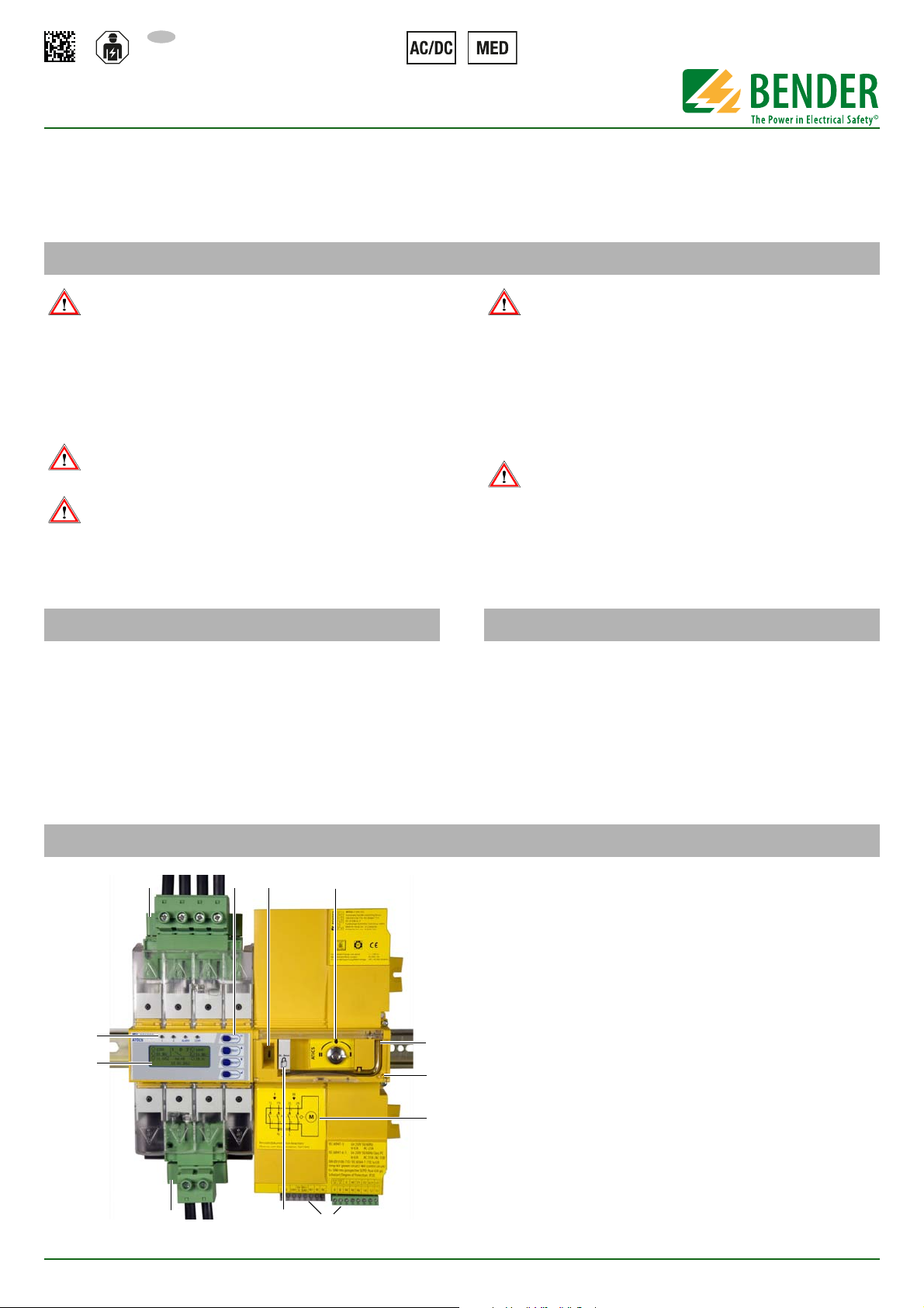
4. Device overview
ATICS-2-ISO_D00046_02_Q_XXEN/09.2016
1. Green plug device for Line 1 and Line 2
2. Control buttons
3. Inspection window for switch position
4. Selector switch for manual mode selection, also shows the
switch position.
5. Allen key for manual mode
6. Transparent cover for changeover switch (manual mode), sealable
7. Wiring diagram for lines 1, 2 and 3
8. Three coded connector plugs
9. Locking device for switch position 0
10. Green plug device for Line 3
11. LCD
12. Operating and alarm LEDs
1
ATICS-2…-ISO Quick start
234
176
115,3
14,7
52
220
263
132
132
245
M5
18
46
73,5
52
45
222
47
*
**
***
***
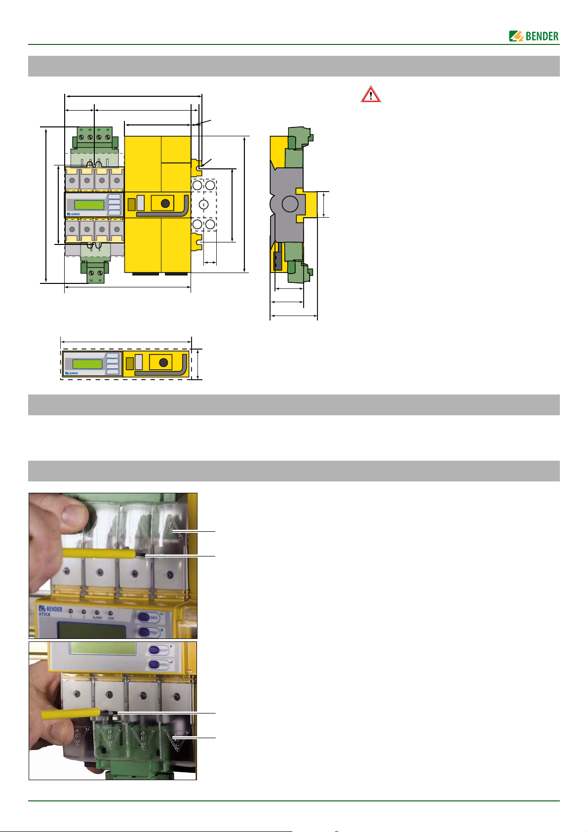
Caution: Risk of destruction by plastering
Liquid plaster may run into the device and the device
may jam.
► Do not seal the device with plaster.
ATICS® is suitable for DIN rail mounting or screw
mounting on plate. To guarantee the protection
against accidental contact, it is to be installed behind a plastic cover.
* Additional space required for the auxiliary con-
tact when using a bypass switch
** Adapt the cutout to the terminal cover
*** Dimensions for screw mounting on mounting
plate
A
B
A
B
5. Dimensions
6. Tools required
► We recommend to use the following tools for connecting the
power section and the control cables:
7. Removing the terminal covers
• Torx® screwdriver T20 or 6.5 x 1.2 mm
• Screwdriver 2.5 x 0.4 mm
• Allen key 4 mm
1. Push back the locking hook (B) in the middle of the top and
bottom terminal (A) cover by using a screwdriver.
2. Remove the terminal cover.
2
ATICS-2-ISO_D00046_02_Q_XXEN/09.2016
8. Mounting the ATICS® on DIN rail
C
D
E
D
C
C
AB
ATICS-2…-ISO Quick start
1. Place the ATICS® on the top edge of the rail.
2. Use a screwdriver to pull down the lower yellow slide lock (C)
and snap the ATICS® into place with slight pressure. Check that
the slide lock is properly snapped into position by pulling
slightly the lower part of the enclosure.
3. Secure all terminals including the unused terminals with Allen
screws.
Tightening torque: 5 Nm.
4. Fasten the terminal covers.
Tighten the mounting screws (D) (PZ1, 8.8 lb-in, 1 Nm).
Caution: If the screws are not tightened, ATICS can be damaged
by the vibrations of the switch-over.
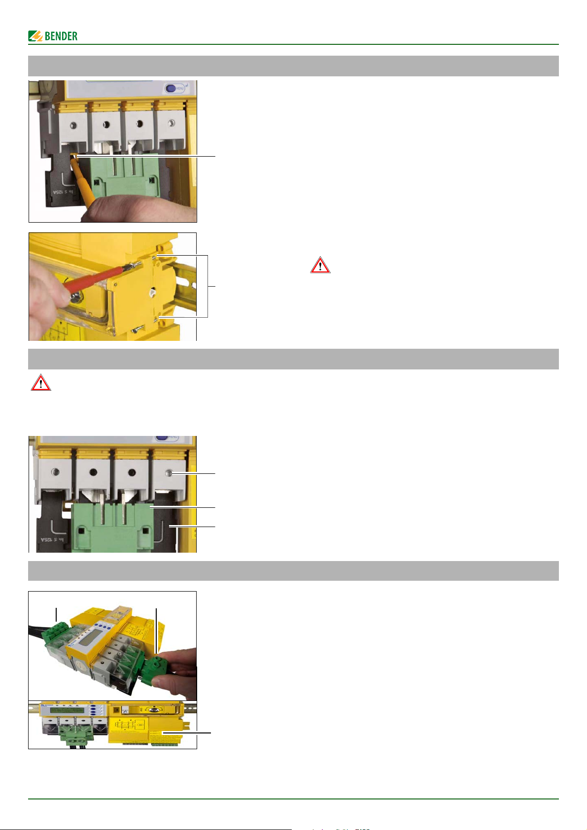
9. Mounting the ATICS® on mounting plate
Warning: Screw heads or washers reduce voltage clearance
Provide for sufficient clearance to live conductors (voltage clearance) by using mounting screws with flat screw heads and flat washers. If mounted on
electrically conductive material: the mounting plate has to be earthed and the area under the terminals has to be covered with insulating material. It is
the responsibility of the mounting staff to select the appropriate mounting plate and mounting screws and to keep the prescribed torque setting.
1. Undo the Allen screws of the terminals (C).
2. Remove the green connectors (D) top and bottom
3. Remove the black bridge (E) bottom
4. Fasten the ATICS® to the mounting plate with M5 (22 lb-in, 2.5
Nm) mounting screws (see dimension diagram).
5. Insert the black bridge (E), bottom
6. Plug in the green plug connectors (D) top and bottom
7. Tighten the Allen screws on the terminals (C).All terminals,
including the unused terminals must be fully tightened.
Tightening torque: 5 Nm.
8. Fasten the terminal covers.
10. Fastening, inserting and securing connections
Connect the terminals according to the wiring diagram to the plug
connectors (A, B) and the three connector plugs (C).
• Connect the lines 1, 2 and 3 to the plug connectors (A, B) with
a Torx® screwdriver T20 or a slotted screwdriver 6.5 x 1.2 mm.
Consider a stripping length of 20 mm and do not use ferrules.
Tightening torque: 2.5 Nm (≤ 25 mm²) or 4.5 Nm (≥ 25 mm²).
The connecting wires must be laid so that they are short-circuit and earth-fault proof!
• Connect the connector plugs (C) with a slotted screwdriver of
2.5 x 0.4 mm. Stripping length: 7 mm. Tightening torque:
0.22…0.25 Nm.
1. Insert bottom green plug connector (B) and secure with
mounting screws. After that, insert top green plug connector
(A) and secure with mounting screws.
2. Insert the other three connector plugs (C).
3. ATICS…400 only: Connect connector plug on the top of the
housing (opposite side of (C)).
ATICS-2-ISO_D00046_02_Q_XXEN/09.2016
3
 Loading...