

Page 1
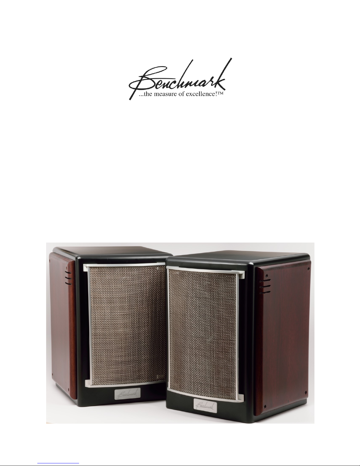
Benchmark SMS1
Instruction Manual
Stand-Mount 2-way Speaker System
Page 2

Overview
Thank you for selecting the Benchmark SMS1 2-way speaker system.
These speakers are designed to provide exceptional clarity, low distortion, and an excellent
frequency response. The silk dome tweeter was selected for its predictable, clean, and uniform
high-frequency response. A smooth low-frequency extension was achieved using an acousticsuspension enclosure and a custom designed copolymer woofer. This port-free enclosure eliminates
the noise that can be created by port turbulence, while achieving a more uniform low-frequency
response.
We have selected the finest crossover components available. We have specified ClarityCap film
capacitors in custom-built precision values. These capacitors contribute to the exceptional vocalrange clarity of the SMS1 speakers. Likewise, we have specified precision wound air-core inductors
and have eliminated the more typical iron-core inductors. Air-core inductors totally eliminate the
distortion that can be caused by core materials. The precision capacitors and inductors minimize
crossover variations and provide precise unit to unit matching. This precise matching contributes to
the exceptional stereo imaging of the SMS1.
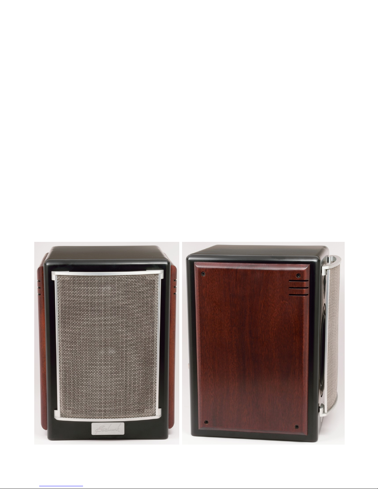
The speaker grills are constructed from acoustically transparent microphone grill material. These
grills provide exceptional protection and a unique appearance while outperforming cloth or foam
grills.
Unique features include high-performance NL4 twist-lock input connectors, a bi-amp switch, and a
choice of furniture-grade hardwood side panels.
SMS1 Instruction Manual Rev B Page 2
Page 3

Contents
Overview 2
Safety Information 4
Provide a Stable Mounting Surface 4
Secure all Cords 4
Risk of Hearing Damage 4
Magnetic Interference 4
Quick Start Guide 5
Speaker Placement 5
Amplifier Selection 6
Amplifier Connections 6
BI-AMP Switch 7
Break-In Period 7
Proper Care 7
Grill Removal and Insertion 7
Bi-Amp and Bi-Wire Operation 8
Bi-Amp Operation 8
Bi-Amp Operation May Reduce Power Amplifier IMD 8
Using Bi-Amp Mode to Add Correction Processors 8
Bi-Wire Operation 8
Technology 9
Crossover 9
SpeakON NL2 and NL4 Cables and Connectors 10
Woofer 10
Tweeter 10
Acoustic Suspension 11
Speaker Grills 11
Specifications 12
Drivers 12
Passive Crossover 12
BI-AMP Mode 12
Input Connectors 12
Dimensions 12
Weight 12
Performance 13
Frequency Response Plots 13
Regulatory Compliance 14
RoHS Compliance Statement 14
Warranty Information 15
Benchmark 1-Year Warranty 15
Benchmark Extended Warranty Options 16
Notes on Warranty Repairs 16
SMS1 Instruction Manual Rev B Page 3
Page 4

Safety Information
Provide a Stable Mounting Surface
Do not place this product on an unstable cart, shelf, stand, bracket, or tripod. The unit may fall,
causing serious injury and/or serious damage. Support must be stable, and must be capable of
supporting the weight of the product. Many speaker stands have provisions for adding ballast to
improve stability - use this feature when available.
Secure all Cords
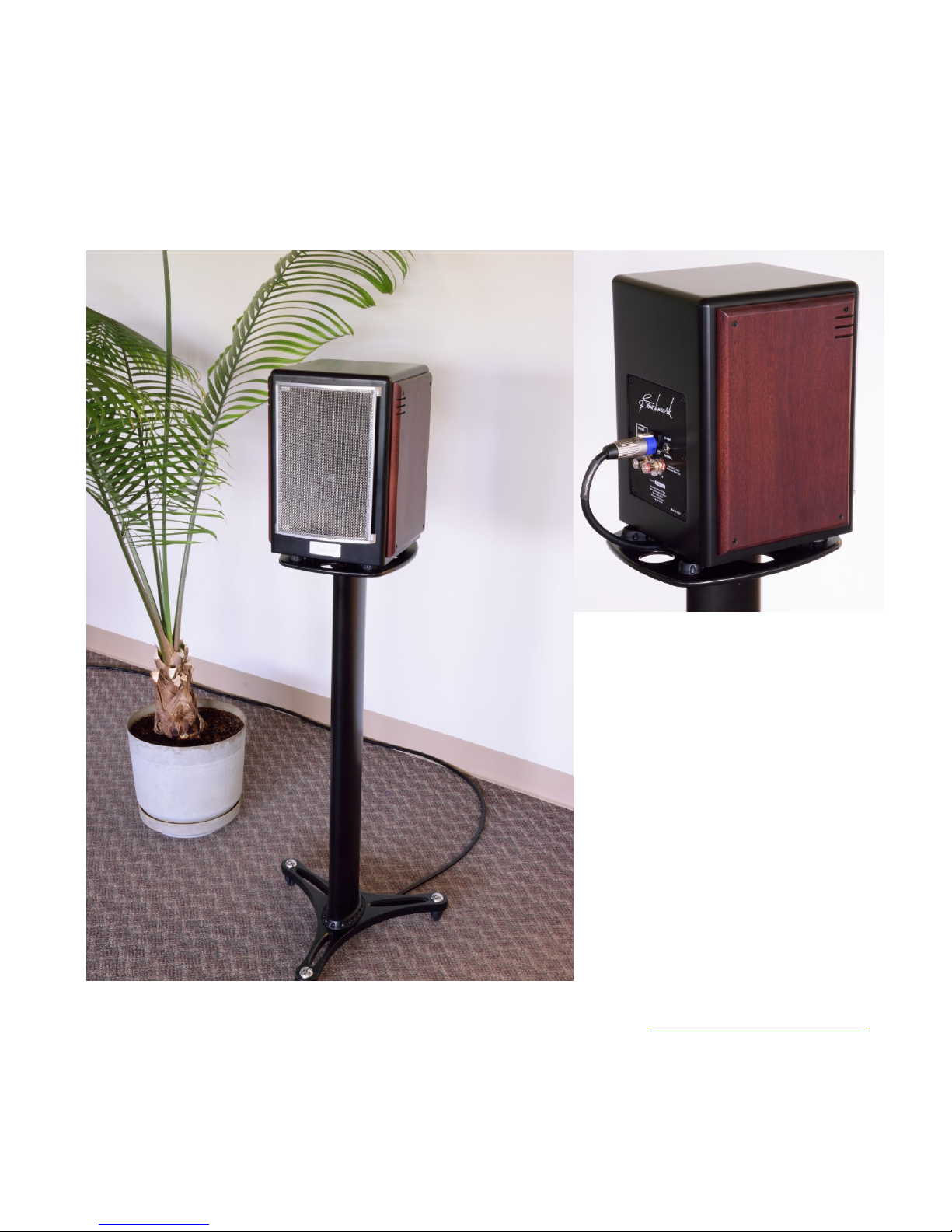
Speaker cords can cause a tripping hazard and may cause a speaker to fall. Keep all cords away
from areas where they could cause a tripping hazard. When using stands, cords should exit from
the bottom of the stand, or should be secured at the bottom of the stand. Cords should always be
secured to prevent pulling the speaker from its mounting.
Risk of Hearing Damage
High sound pressure levels can damage your hearing. Do not get close to the speakers when
operating them at high volumes.
Magnetic Interference
Loudspeaker drivers are electro-magnetic devices. They emit magnetic fields that may interfere
with older CRT-type monitors. Do not place magnetic items near the drivers. Magnets and
magnetic materials can damage the drivers.
SMS1 Instruction Manual Rev B Page 4
Page 5

Quick Start Guide
Thank you for selecting the Benchmark SMS1 loudspeakers. The suggestions in this guide will help
you to get the most enjoyment from these high-quality speakers. If you have questions, our
support staff is available at 1 800-BNCHMRK, +1-800-262-4675, +1-315-437-6300, or at
[email protected] Please do not hesitate to contact us. We are here to help.
Speaker Placement
Provide a Stable Mounting Surface
A stable vibration-free mounting surface is important for achieving proper stereo imaging. It is also
an essential consideration for safety.
Do not place this product on an unstable cart, shelf, stand, bracket, or tripod. The unit may fall,
causing serious injury and/or serious damage. Support must be stable, and must be capable of
supporting the weight of the product. Many speaker stands have provisions for adding ballast to
improve stability - use ballast features when available.
Orientation
The SMS1 speakers are designed to be oriented vertically (tweeter above the woofer). Do not
place the speakers on their sides.
Height
The SMS1 should be mounted so that the tweeters are at ear height, or a few inches above ear
height. If the speakers must be mounted higher or lower than this, they should be angled so that
the tweeters point directly toward or slightly above the listener's ears.
Distance to Listening Position
The SMS1 speakers should be located 4 to 16 feet from the listening position. Both speakers
should be exactly the same distance from the primary listening position.
The Stereo Triangle
Ideally, the speakers and the listener should form a triangle where the listener is exactly the same
distance from both speakers. The distance between the speakers should be 6 to 8 feet, but should
not be more than the distance between the listener and the speakers.
Optimum stereo imaging is only achieved when the listener is exactly the same distance from both
speakers. The two sides of the triangle intersecting the listening position must be equal. Variations
of a few inches will diminish the accuracy of the stereo imaging. When this geometry is incorrect,
center-stage high-frequency sounds will move out to the right and left speakers. We recommend
measuring the distance between the listening position and the speakers.
Toe In
The speakers should be angled directly toward the listener.
SMS1 Instruction Manual Rev B Page 5
Page 6
Room Interactions
No listening space is perfect, but proper speaker placement can reduce undesirable interactions
with the room.
Avoid reflective surfaces such as walls and furniture.
Keep the speakers more than 2 feet in front of any walls.
Avoid placing the speakers near room corners.
Avoid placing speakers near side walls.
Avoid placing the listening position too close to the rear wall.
Improper placement near walls will stimulate room modes and will enhance the bass response. This
will often create an excessive and uneven bass response. If some enhancement of the bass is
desired, move the speakers slightly closer to the walls. Use caution, room modes can produce
significant peaks in the low-frequency response.
Reflective side surfaces will interfere with stereo imaging. If speakers cannot be moved away from
side surfaces, these surfaces can be treated with acoustic materials, or angled away from the
listening position, to minimize reflections. Surfaces that reflect an image of the speaker directly to
the listening position should be given the most attention.
Amplifier Selection
Recommended amplifier power is 30 - 200 Watts. The Benchmark AHB 2 is an ideal match for the
SMS1 speakers. The AHB2 delivers 160 Watts per channel into the 6-Ohm SMS1. There is no
need to run the AHB2 in mono mode as this will overpower the SMS1 speakers.
Amplifier Connections
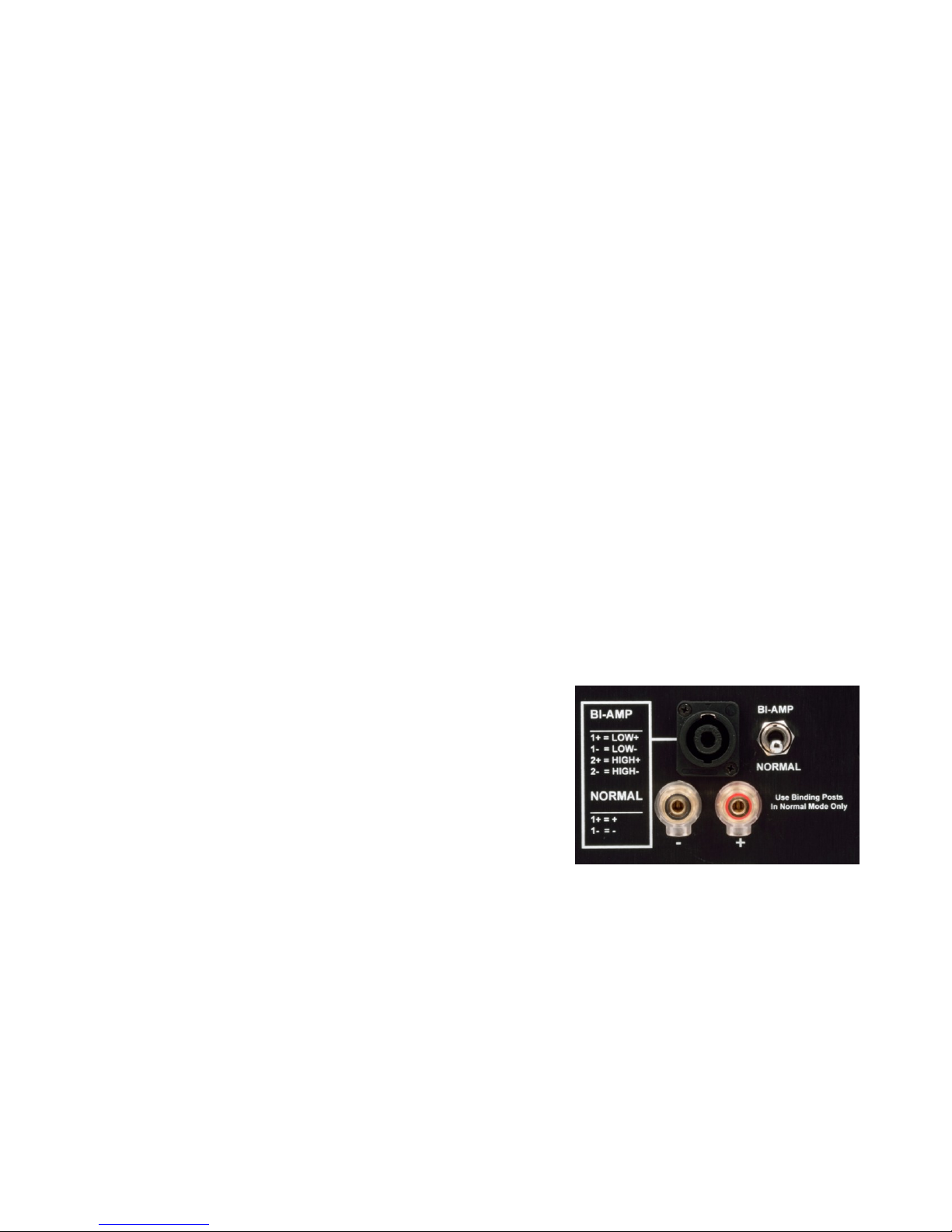
The SMS1 has two sets of input connections; traditional
binding posts, and high-performance SpeakON NL4 twistlock speaker connectors. Both sets of connectors support
standard 2-wire connections from the power amplifier. The
NL4 connectors also provide separate connections to the
high-frequency and low-frequency sides of the crossover
network when the BI-AMP switch is activated.
The NL4 connectors are compatible with 4-pole NL4 plugs or
2-pole NL2 plugs. Use two-pole NL2 pugs and cable for standard wiring. Use four-pole NL4 pugs
and cable for Bi-Wire and BI-AMP applications.
If you choose to use the binding posts, be careful to keep all connections properly polarized
(connect + to + and - to -). Do not turn the power amplifier on until all binding post connections
are secured.
SMS1 Instruction Manual Rev B Page 6
Page 7

BI-AMP Switch
The BI-AMP switch must be set to NORMAL for most applications. It must always
be set to NORMAL when using the binding posts. If this switch is in the wrong
position, no damage will occur, but the high-frequency driver may not receive an
input signal.
Break-In Period
The SMS1 speakers require a 20 to 30 hour break-in period to reach full performance. Speaker
drivers are electro-mechanical devices and the materials used in these devices undergo minor
mechanical changes during the break-in period. You should hear increased energy in the lowest
octave, and a more relaxed midrange, when the break-in period is completed.
Proper Care
Your speakers carry a warranty against defects. However, the warranty does not cover failure from
abuse. Please use good judgment.
A clipping power amplifier can produce unusually high levels at the input to the tweeter. Tweeter
failures are often related to underpowered or overdriven systems.
The woofer can be damaged by excessive power.
Do not touch the silk-dome tweeter. It is very delicate and is easily damaged.
Grill Removal and Insertion
The speaker grills are designed to protect the drivers from accidental contact while providing
excellent acoustic transparency. We recommend keeping the grills in place.
Each grill is attached with four press-fit pins and sockets. There is one pin on each corner of the
grill. Use extreme care when attaching or removing grills.
To remove grill:
Grasp the bottom of the frame and gently pull the grill until the two bottom pins are free.
Grasp the top of the frame and gently pull to clear the remaining two pins.
Avoid twisting the grill frame when inserting or removing.
Do not pull or press on the sides of the grill frame.
To insert grill:
Grasp the top of the frame and gently insert the two top pins.
Grasp the bottom of the frame and gently insert the two bottom pins.
Avoid twisting the grill frame when inserting or removing.
Do not pull or press on the sides of the grill frame.
SMS1 Instruction Manual Rev B Page 7
Page 8

Bi-Amp and Bi-Wire Operation
Bi-Amp Operation
Set the switch to BI-AMP when driving the tweeter and woofer from separate amplifiers. In BIAMP mode, two amplifier channels will be required for each speaker. A four-pole NL4 cable is
required for all BI-AMP applications. In BI-AMP mode, the passive crossover is split into separate
high and low frequency sections. Both drivers still receive the proper range of frequencies and no
external crossover is required. This topology simplifies the use of the BI-AMP mode while
protecting the drivers from incorrect wiring.
Bi-Amp Operation May Reduce Power Amplifier IMD
BI-AMP connections use separate amplifiers to drive the woofer and tweeter. With many
amplifiers, this will reduce IMD (intermodulation distortion) and may improve the sound quality.
Please note that it is not necessary to use a Benchmark AHB2 in BI-AMP mode. The AHB2 is
virtually distortion free, and the use of bi-amplification will not reduce distortion. However, biamplification can offer an opportunity to add separate active filters for the high-frequency and lowfrequency drivers. In such a system, a Bi-AMP connection from an AHB2 will allow fine-tuning of
driver and room response.
Using Bi-Amp Mode to Add Correction Processors
BI-AMP connections provide an opportunity to fine-tune the frequency-domain and time-domain
response of the speakers and room using external active processing. This processing can be added
as an analog process (between the DAC and power amplifier), or as a digital process (before the
DAC). If the correction is digital, two channels of D/A conversion and two channels of amplification
will be required for each speaker. If the correction is analog, there is no need to duplicate the
number of D/A channels, but two channels of amplification will still be required for each speaker.
When using a Benchmark AHB2 for BI-AMP connections, connect the four-pole NL4 cable to the
"1&2" output connector on the AHB2. Channel 1 drives the woofer, channel 2 drives the tweeter.
Bi-Wire Operation
The SMS1 supports Bi-Wire connections when the speakers are set to BI-AMP mode. Bi-Wire
connections use separate conductors for the woofer and tweeter. Unlike BI-AMP connections, both
sets of conductors are driven from a common amplifier channel. Bi-Wire connections offer no
advantages when high-quality cables are used over relatively short runs. Bi-Wire connections may
be useful for long cable runs. Special four-pole cables are required for Bi-Wire connections. The
high-frequency and low-frequency conductors must be connected together at the power amplifier,
but must be connected to separate pins in the NL4 plug. Pin assignments are shown on the rear
plate of the SMS1.
SMS1 Instruction Manual Rev B Page 8
Page 9
Technology
Crossover
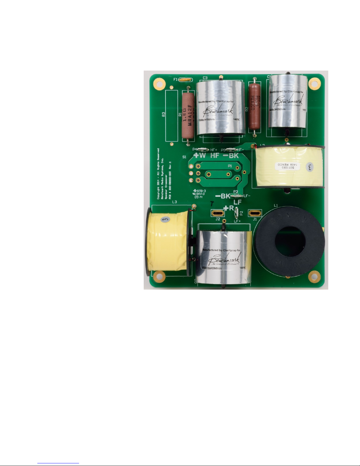
The SMS1 has remarkable vocal
clarity. Much of this can be
attributed to the low-distortion
crossover design and to the choice
of the crossover frequency.
To achieve unusually low
distortion, the SMS1 crossover
uses some of the highest-quality
components available.
Film Capacitors
The SMS1 uses film capacitors
custom-built for Benchmark by
ClarityCap. Metalized
polypropylene film capacitors
produce much less distortion than
other types of capacitors. In our
opinion, ClarityCap builds the best
audio capacitors available. Each
capacitor is built to tight tolerances
at the exact non-standard values
required for our crossover.
ClarityCaps are mathematically
modeled and designed to minimize
microphonic effects that can cause
high-frequency distortion.
Air-Core Inductors
Most passive crossovers use at least one iron-core inductor. The iron-core reduces the size and
cost of the inductor, but can increase distortion. We chose to entirely eliminate iron-core inductors
from the SMS1 crossover. This choice eliminates harmonic distortion caused by low-bass
frequencies interacting with the iron core. This distortion usually adds clutter to the mid-bass and
vocal frequencies. In our listening tests, we preferred the clean sound of the 100% air-core design.
Strategic Crossover Layout
Crossover inductors can interact with each other and with the voice coils on the drivers. The SMS1
crossover placement and layout are specifically designed to minimize these inductive interactions.
This reduces unwanted variations in the frequency response while reducing the distortion that can
be caused by inductor crosstalk.
SMS1 Instruction Manual Rev B Page 9
Page 10
Non-Inductive Wire-Wound Resistors
Wire-wound resistors have excellent temperature coefficients. This prevents changes in resistance
that can occur when resistors are heated by music power. Crossover resistors dynamically change
temperature at the peaks of music waveforms. The low temperature coefficient keeps the
resistance constant and prevents thermally-induced distortion.
The resistors used in the SMS1 are also specially wound to minimize inductance. This construction
eliminates interactions between the resistors and inductors, while producing a resistor that behaves
in an ideal manner.
3 kHz Crossover Frequency
The SMS1 uses a higher crossover frequency than most 2-way speakers of similar size. Most 2way speakers place the crossover right in the middle of the vocal band. At 3 kHz, the SMS1
crossover is comfortably above the vocal range and this improves the clarity of the vocals.
SpeakON NL2 and NL4 Cables and Connectors
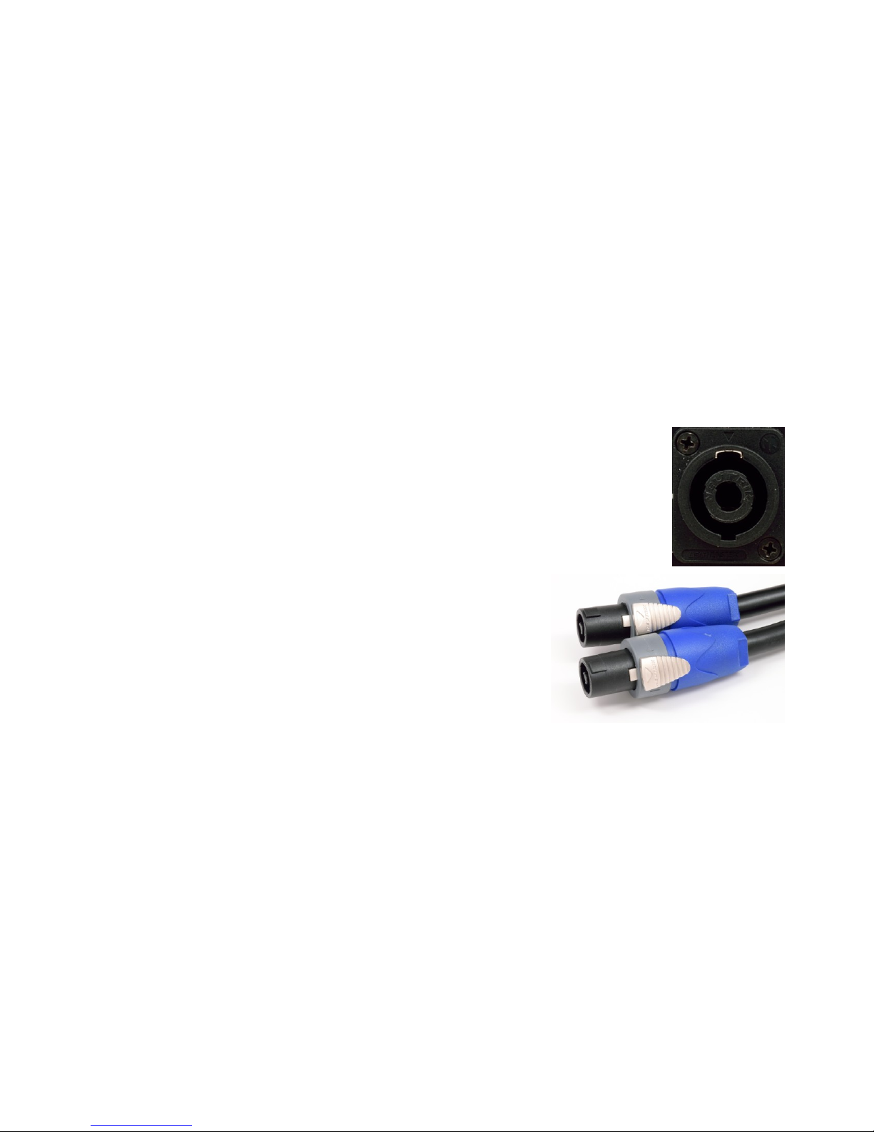
The NL4 connectors on the SMS1 provide very low impedance connections and
are rated for high-current professional applications. The NL4 connectors are
rugged, reliable, and easy to use. In our tests, they consistently outperformed
binding post connections. The NL4 connector can be used with four-pole NL4
plugs, or two-pole NL2 plugs.
The NL4 connectors also prevent polarity reversals, loose
wires, and short circuits. We highly recommend selecting NL4
or NL2 cables instead of cables that use traditional binding-post
terminations.
The Benchmark AHB2 power amplifier is also equipped with
NL4 SpeakON connectors. This makes system set-up quick,
easy, and reliable.
Use a pair of two-pole NL2 to NL2 cables to connect one AHB2 power amplifier to a pair of SMS1
speakers operating in NORMAL mode. Use a pair of four-pole NL4 to NL4 cables to connect two
AHB2 power amplifiers to a pair of SMS1 speakers operating in BI-AMP mode.
Woofer
The proprietary 6.5" woofer features a copolymer cone and a long excursion. It is specifically
designed for use in our acoustic suspension cabinet.
Tweeter
The 25 mm soft dome tweeter was selected after extensive listening tests. It provides clean,
accurate, and detailed high-frequency output with low unit-to-unit variance.
SMS1 Instruction Manual Rev B Page 10
Page 11
Acoustic Suspension
We know that small ported loudspeakers have become fashionable. We don’t do fashion. Ported
speakers create the illusion of bass extension by emphasizing certain frequencies (hence the name
"tuned port"). In smaller speaker enclosures, ports often produce a non-linear bass response sometimes described as “one note bass”. Ports can make a small speaker seem large, but accuracy
can suffer in the name of big bass.
Ports can also create turbulence that can produce a "chuffing" sound. Smaller enclosures often
have high-velocity ports that suffer from this problem.
The SMS1 is an acoustic suspension loudspeaker; it has a sealed cabinet, without ports. By nature,
it is more linear than a ported design. It can still produce impressively deep bass. The trade-off is
efficiency. The SMS1 will require slightly more power than comparably sized ported designs.
Speaker Grills
The stainless steel mesh used on the speaker grills was originally designed for microphone screens.
The material is designed to provide acoustic transparency while providing substantial protection to
precision microphones. It's rigid appearance may give the impression that it is not transparent, but
it actually outperforms most cloth grills while providing a unique appearance.
SMS1 Instruction Manual Rev B Page 11
Page 12

Specifications
The SMS1 is a 2-way passive acoustic-suspension monitor/loudspeaker with BI-AMP capabilities.
Drivers
170 mm Custom Copolymer Low-Frequency Driver
25 mm Soft Dome High-Frequency Driver
Passive Crossover
Air-Core Inductors for Minimal Distortion - Custom Built for Benchmark
Top-Quality Precision Film Capacitors - Custom Built for Benchmark
Non-Inductive Wire-Wound Power Resistors
Precision Component Tolerances for Precise Matching
Asymmetric Crossover Optimization
3 kHz Crossover Frequency
BI-AMP Mode
Switch-Selected BI-AMP Mode
Uses NL4 4-Pole Input Connector
Input Connectors
One SpeakON NL4 High-Current 4-Pole Twist-Lock Input Connector
Two Fully-Insulated Multi-Way Binding Posts
Dimensions
10.75" W x 13.5" H x 9.87" D (270 mm W x 345 mm H x 250 mm D)
Recommended Stand Height: 29" to 36" (736 to 914 mm) - Floor to Base of Cabinet
Weight
Unit Weight: 23 lbs. (10.4 Kg) - One Speaker with Grill
Shipping Weight: 52 lbs. (23.6 Kg) - Speaker Pair in Single Carton
SMS1 Instruction Manual Rev B Page 12
Page 13
Performance
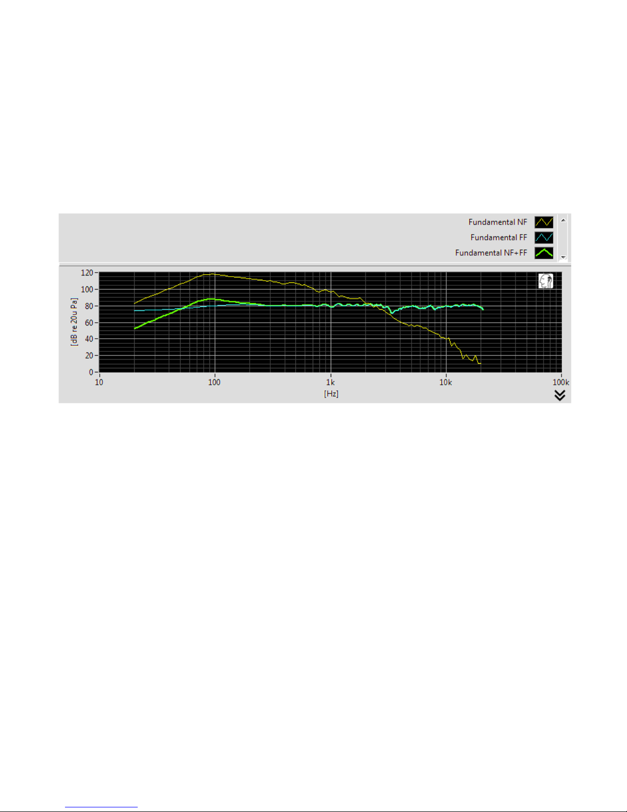
Frequency Response: 44 Hz - 22 kHz
Crossover Frequency: 3 kHz
Sensitivity: 88 dB
Input Impedance: 6 Ohms
Recommended Power: 30 - 200 W
Frequency Response Plots
The green curve shows the combined response of the woofer and tweeter at a distance of 6 feet.
The measurement is on-axis with the tweeter.
The yellow curve shows the near-field response measured at the woofer.
The blue curve shows the far-field response measured at a distance of 6 feet.
The measurement system combines the near-field and far-field measurements in order to calculate
the anechoic combined response shown by the green curve.
SMS1 Instruction Manual Rev B Page 13
Page 14

Regulatory Compliance
RoHS Compliance Statement
This statement clarifies Benchmark Media Systems, Inc. product compliance with the EU’s
(European Union) directive 2002/95/EC, or, RoHS (Restrictions of Hazardous Substances).
As of July 01, 2006, All Benchmark Media Systems, Inc. products placed on the European Union
market are compliant (containing quantity limit weight less than or equal to 0.1% (1000 ppm)
of any homogeneous Lead (Pb), Mercury (Hg), Hexavalent Chromium (Cr VI), and flame
retardant Polybrominated Biphenyls (PBB) or Polybrominated Diphenyl Ethers (PBDE)).
SMS1 Instruction Manual Rev B Page 14
Page 15

Warranty Information
The Benchmark 1-Year Warranty
Benchmark Media Systems, Inc. warrants its products to be free from defects in material and
workmanship under normal use and service for a period of one year from the date of
delivery.
This warranty extends only to the original purchaser. This warranty does not apply to fuses,
lamps, batteries, or any products or parts that have been subjected to misuse, neglect,
accident, modification, or abnormal operating conditions.
In the event of failure of a product under this warranty, Benchmark Media Systems, Inc. will
repair, at no charge, the product returned to its factory. Benchmark Media Systems, Inc. may,
at its option, replace the product in lieu of repair. If the failure has been caused by misuse,
neglect, accident, or, abnormal operating conditions, repairs will be billed at the normal shop
rate. In such cases, an estimate will be submitted before work is started, if requested by the
customer.
Attempts to deliberately deface, mutilate, or remove the product's label will render this
warranty void. Benchmark will not honor warranties for any products disingenuously purchased
on the US or Canadian markets for export.
The foregoing warranty is in lieu of all other warranties, expressed or implied, including but not
limited to any implied warranty of merchantability, fitness or adequacy for any particular
purpose or use. Benchmark Media Systems, Inc. shall not be liable for any special, incidental,
or consequential damages, and reserves the right to change this information without notice.
This limited warranty gives the consumer-owner specific legal rights, and there may also be
other rights that vary from state to state.
Benchmark 1-Year Warranty
SMS1 Instruction Manual Rev B Page 15
Page 16

The Benchmark Extended 5-Year Warranty *
Benchmark Media Systems, Inc. optionally extends the standard 1-year warranty to a period of
five years from the date of delivery.
*For the extended warranty to become effective, the original purchaser must register the
product at the time of purchase either by way of the enclosed registration card or through the
product registration section of the Benchmark Media Systems, Inc. website. This optional
warranty applies only to products purchased within the US and Canada and is extended only to
the original purchaser.
Attempts to deliberately deface, mutilate, or remove the product's label will render this
warranty void. Benchmark will not honor warranties for any products disingenuously purchased
on the US or Canadian markets for export. The terms of the extended warranty are subject to
change without notice. For products purchased outside the US and Canada, please refer to the
Extended Two 2-Year International Warranty.
The Benchmark Extended 2-Year International Warranty **
Benchmark Media Systems, Inc. optionally extends the standard 1-year warranty to a period of
two years from the date of delivery.
**For the extended warranty to become effective, the original purchaser must register the
product at the time of purchase either by way of the enclosed registration card or through the
product registration section of the Benchmark Media Systems, Inc. website. This optional
warranty applies only to products purchased outside the US and Canada and is extended only
to the original purchaser.
Attempts to deliberately deface, mutilate, or remove the product's label will render this
warranty void. Benchmark will not honor warranties for any products disingenuously purchased
on the US or Canadian markets for export. The terms of the extended warranty are subject to
change without notice. For products purchased in within the US and Canada, please refer to the
Extended Five 5-Year Warranty.
Notes on Warranty Repairs
An RMA (return merchandise authorization) number, issued by our Customer Service
Department, is required when sending products for repair.
They must be shipped to Benchmark Media Systems prepaid and preferably in their original
shipping carton with the RMA number clearly visible on the exterior of the packaging. A letter
should be included giving full details of the difficulty.
Benchmark Extended Warranty Options
SMS1 Instruction Manual Rev B Page 16
Page 17
Made in the USA
All Benchmark products are
designed and manufactured in the
USA.
Copyright © 2014
Benchmark Media Systems, Inc.
All rights reserved.
Benchmark Media Systems, Inc.
Benchmark Media Systems, Inc.
203 East Hampton Place, STE 2
Syracuse, NY 13206-1633
USA
PHONE: +1-315-437-6300
FAX: +1-315-437-8119
www.benchmarkmedia.com
SMS1 Instruction Manual Rev B Page 17
Page 18

SMS1 Instruction Manual Rev B Page 18
 Loading...