

Page 1
6 720 610 893-01.TD
Installation and Servicing Instructions
RD 532i/RD 537i/RD 542i combi
Wall mounted condensing boiler for central heating and mains
fed domestic hot water
ZWBR 7-32 RD 532i GC-Number: 41 108 10
ZWBR 11-37 RD 537i GC-Number: 41 108 11
ZWBR 11-42 RD 542i GC Number: 41 108 12
6 720 611 447 GB (03.11) TD
Page 2

6 720 611 447 GB (03.11)
Contents
2
Contents
Safety precautions 3
Symbols 3
1 Details of the appliance 4
1.1 EC Declaration of Conformity 4
1.2 Standard package 4
1.3 Description of appliance 4
1.4 Accessories 5
1.5 Casing dimensions 5
1.6 Layout of appliance 6
1.7 Function 7
1.8 Electrical wiring diagram 8
1.9 Technical data 9
2 Installation regulations 10
3 Installation 11
3.1 Important remarks 11
3.2 Domestic hot water 11
3.3 Sealed systems 11
3.4 Siting the appliance 12
3.5 Wall mounting frame assembly 13
3.6 Pre-piping the system 13
3.7 Fitting the appliance 14
3.8 Checking the connections 15
3.9 Flue Systems 15
3.9.1 Siting the Flue Terminal 16
3.9.2 Installation of the flue 17
3.9.3 Flue duct preparation and assembly 18
4 Electrical connections 20
4.1 Connecting the appliance 20
4.2 Connecting a TR2 Room Thermostat 21
4.3 Mains Voltage external controls connections 21
5 Commissioning 22
5.1 Commissioning 22
5.2 Switching the appliance on/off 23
5.3 Switching on the central heating 23
5.4 System controls 23
5.5 Setting the domestic hot water temperature and flow
rate 24
5.5.1 Domestic hot water temperature 24
5.5.2 Hot water flow rate 24
5.6 Summer mode (hot water only) 24
5.7 Frost protection 24
5.8 Pump anti-seize function 24
5.9 Fault Condition 25
5.10 Appliance Data Monitoring 25
6Text Display 26
6.1 General Description 26
6.2 Programming 26
6.2.1 Deleting a setting 27
6.2.2 Resetting all parameters to their original settings 27
6.3 Menu structure 27
6.4 Setting the time/day 28
6.4.1 Setting the time and day 28
6.4.2 Holidays 28
6.5 Heating 28
6.5.1 Heating programme 28
6.5.2 Setting the Economy temp (TR2 connected) 29
6.5.3 Manual operating mode (TR2 not connected) 29
6.6 Hot water 29
6.7 i Info 29
6.8 Settings 30
6.8.1 Heating (if TR 2 is connected) 30
6.8.2 Hot Water (Storage Tank, system models only) 30
6.8.3 Service 30
6.9 Individual timer programmes 30
7 Individual settings 31
7.1 Mechanical settings 31
7.1.1 Checking the size of the expansion vessel 31
7.1.2 Setting the central heating flow temperature 31
7.2 Settings on the Bosch Heatronic 31
7.2.1 General description 31
7.2.2 Setting the anti-cycle time
(Service Function 2.4) 32
7.2.3 Setting the maximum CH flow temperature (Service
Function 2.5) 32
7.2.4 Setting the heating output
(Service Function 5.0) 32
7.2.5 Constant hot water cycle time
(Service Function 6.8) 32
7.2.6 Variable pump settings
(Service Function 7.0) 32
7.3 Setting the gas/air ratio 32
8 Converting the appliance to different gas types 33
8.1 Setting the gas/air ratio 33
8.2 Test combustion air/flue gas at set heat output 35
8.2.1 Test the O2 or CO2 level in the combustion air 35
8.2.2 Testing CO and CO2 35
9 Maintenance 36
9.1 Pre-Service Check List 37
9.2 Description of servicing operations 38
9.3 Replacement of Parts 41
9.3.1 PCB control board and transformer 41
9.3.2 Fan Assembly 42
9.3.3 Pump 42
9.3.4 3-way diverter valve 43
9.3.5 3-way diverter valve motor 43
9.3.6 Sensors 43
9.3.7 Gas Valve 44
9.3.8 Domestic Hot Water Heat Exchanger 44
9.3.9 Electrode assembly 44
9.3.10 Pressure gauge 44
9.3.11 Expansion vessel 44
9.3.12 Pressure Relief Valve 44
9.3.13 Burner 44
9.3.14 Flow switch 45
9.3.15 Primary Heat Exchanger 45
10 Appendix 46
10.1 Fault Codes 46
10.2 Short parts list 47
10.3 Heating/DHW output settings RD532i N.G. 48
10.4 Heating/DHW output settings RD532i L.P.G 48
10.5 Heating/DHW output settings RD537i N.G. 48
10.6 Heating/DHW output settings RD537i L.P.G 48
10.7 Operational Flow diagrams 49
10.7.1 Domestic hot water function 49
10.7.2 Central heating function 50
Page 3
6 720 611 447 GB (03.11)
Safety precautions
3
Safety precautions
If you smell gas
B Turn off gas service cock at the meter.
B Open windows and doors.
B Do not operate any electrical switches.
B Extinguish any naked flames.
B Telephone your gas company.
If you smell fumes from the appliance
B Switch off appliance (see page 23).
B Open windows and doors.
Fitting and modifications
B Fitting of the appliance or any controls to the appli-
ance may only be carried out by a competent engineer in accordance with the Gas Safety (Installation
and Use) Regulations 1998.
B Flue systems must not be modified in any ways other
than as described in the fitting instructions.
B This appliance is for use on sealed primary systems only.
Maintenance
B The user is recommended: to have the system
regularly serviced in order to ensure that it functions
reliably and safely.
B Use only original spare parts!
Combustible materials
B Do not store or use any combustible materials
(paper, thinners, paints etc.) in the vicinity of the
appliance.
Health and safety
B This appliance contains no asbestos products.
B There is no potential hazard due to the appliance
being electrically unsafe.
B There are no substances used in the construction
that are a potential hazard in relation to the COSHH
Regulations (Control of Substances Hazardous to
Health Regulations 1988).
Combustion air/Ambient atmosphere
B The combustion air/ambient atmosphere should be
kept free of chemically aggressive substances (e.g.
halogenated hydrocarbons which contain chlorine or
fluorine compounds). This will prevent corrosion.
Instructions to the customer
B Explain to the customer how the appliance works and
how to operate it.
B Advise the user that he/she must not make any modi-
fications to the appliance or carry out any repairs on it.
B These instructions are to be left with the user or at
the Gas meter.
B Important: These instructions apply in the UK only.
Unpacking
IMPORTANT HANDLING INSTRUCTIONS
B Two people should transfer the packaged appliance
from the van to the point of installation
B Open the top of the carton, remove and place the
component tray and both side bars of the wall mounting frame to one side
B Lie the packaged appliance on its back. (The back
has “TRUCK HERE” printed on the carton)
B One person firmly holds the packaging while the
other straddles the boiler and slides it from the packaging
B Two persons are then required to lift one end and
stand the appliance upright with the flue at the top
Additional requirements for roof space installation
B Two people should use two step ladders and share
lifting the unpacked boiler up to the loft hatch
B Where the boiler enters the loft space, tilt and slide
the boiler on its back to the point of installation
Check the contents against the packing list.
Symbols
Safety instructions in this document
are identified by a warning-triangle symbol and are printed on a grey background.
i
Notes containing important information
are identified by the symbol shown on the
left. They are bordered by horizontal lines
above and below the text.
Page 4
6 720 611 447 GB (03.11)
4
Details of the appliance
1 Details of the appliance
1.1 EC Declaration of Conformity
This appliance is in accordance with the applicable
requirements of the Gas Appliance Directive, Boiler Efficiency Directive, Electromagnetic Compatibility Directive and the Low Voltage Directive.
1.2 Standard package
• Gas condensing combination boiler for central heating and domestic hot water
• Control panel cover
• Wall mounting frame
• Room thermostat TR2
• Fixings (screws etc.)
• Set of documentation for appliance
• Pre-plumbing manifold
• Condensate drain pipe
• Filling loop.
1.3 Description of appliance
• Wall-mounted appliance, siting not dependent on
room size
• Natural gas models are low-emission appliances
• Multi function display
• Bosch Heatronic control system with integrated text
display for service functions and faults
• 3-channel - digital timer for one heating circuit
• Variable pump
• Automatic ignition
• Modulating control
• Full safety systems incorporating Bosch Heatronic
with flame ionisation monitoring, solenoid valves and
temperature sensors
• Concentric flue/air duct with testing point for
CO
2
/CO
• Regulated speed fan
• Pre-mix burner
• Temperature control for central heating
• Temperature sensor in domestic hot water
• Safety temperature limiter in 24 V electrical circuit
• Relief valve, pressure gauge, expansion vessel, Auto
air vent
• Flue gas temperature limiter (105 °C)
• Hot water priority circuit
• Motorised 3-way valve
• Plate-type heat exchange
• Condensate Trap.
PIN CE-0085 BL0507
Category UK II
2H 3P
Appliance Type C13, C
33
Table 1
Page 5
6 720 611 447 GB (03.11)
Details of the appliance
5
1.4 Accessories
• Standard horizontal flue kit at 100 mm outside
diameter for flues up to 4 m in length (3.5m for the R
40 HE).
• Flue duct kits for horizontal (125 mm outside
diameter) for flue lengths up to 13m or 10m (RD537i
& RD542i) and vertical flue systems for flue lengths
up to 13.7m or 10.7m (RD537i & RD542i). Fitting
instructions are sent with these kits.
1.5 Casing dimensions
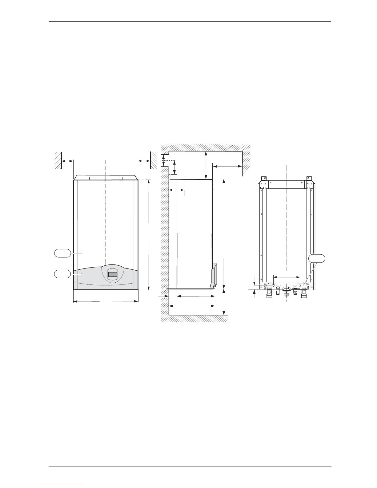
Fig. 1
13 Manifold assembly
101 Outer case
103 Facia cover
X Standard Concentric Horizontal Flue System: min. 160 mm
Alternative Concentric Flue System: min. 220 mm
Y Standard Concentric Horizontal Flue System: 40 mm
Alternative Concentric Flue System: 70 mm
Z Standard Concentric Horizontal Flue System: 105 mm
Alternative Concentric Flue System: 130 mm
* For servicing the appliance
Note: Horizontal flue only: dimension X may need to increase due
to the incline of the flue.
6 720 610 599 - 01.TD
200
30
13
395
360
850
35
X
120
Y
Z
200
*
*
600
m
in .
10*
m
in .
440
850
101
103
10*
Page 6
6 720 611 447 GB (03.11)
6
Details of the appliance
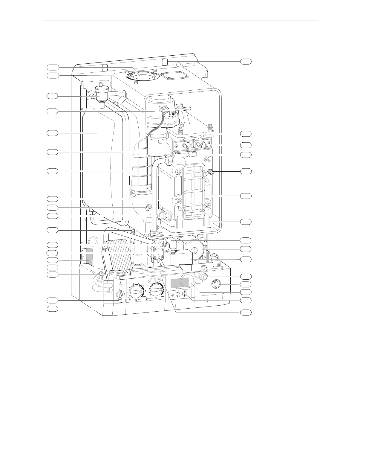
1.6 Layout of appliance
Fig. 2
4 Heatronic control
6 Heat exchanger safety temperature limiter
6.1 Hot water NTC sensor
7 Testing point for gas supply pressure
8.1 Pressure gauge
9 Flue gas temperature limiter
15 Relief valve
18 Pump
20 Expansion vessel
27 Automatic air vent
29 Air gas Mixer unit
32.1 Electrode assembly
36 Temperature sensor in CH flow
43 CH flow
63 Adjustable gas flow restrictor
64 Adjusting screw for min. gas flow volume
88 3-way valve (combi)
98 DHW flow switch (combi)
102 Inspection window
120 Fixing points
221.1 Flue duct
221.2 Co mbustion air intake
226 Fan assembly
295 Appliance type sticker
271 Flue duct
355 Plate-type domestic hot water heat exchanger
358 Condensate trap
396 Hose Condensate trap
400 Text display
415 Cover plate for cleaning access
416 Condensate collector
418 Data plate
423 Siphon
6 720 610 599 - 00.TD
29
98
102
226
271
416
20
43
9
63
358
64
7
355
6.1
4
415
6
36
32.1
295
8.1
18
27
88
15
120
418
400
396
423
221.1
221.2
Page 7
6 720 611 447 GB (03.11)
Details of the appliance
7
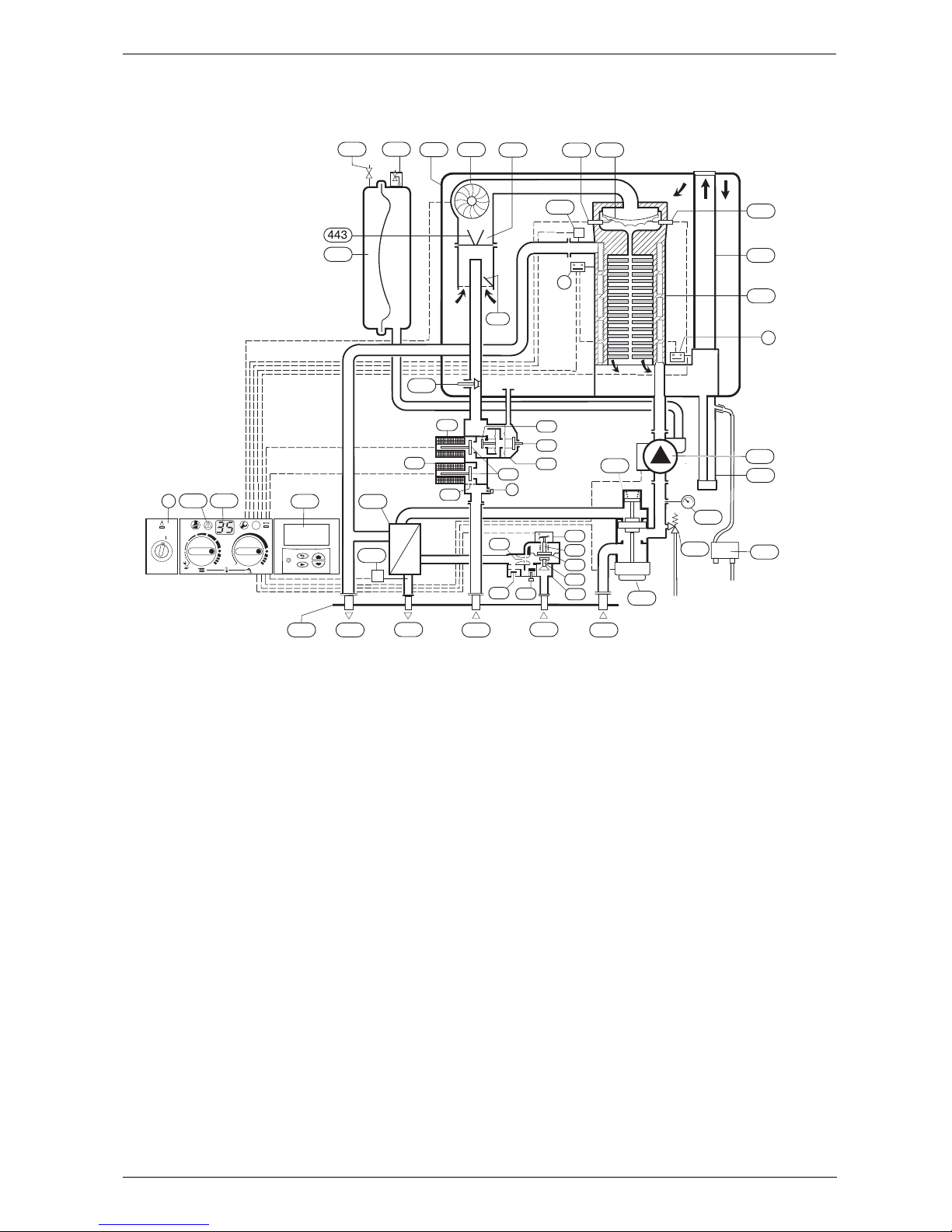
1.7 Function
Fig. 3
4 Bosch Heatronic control
6 Temperature limiter, heat exchanger
6.1 Hot water NTC sensor
7 Testing point for gas supply pressure
8.1 Pressure gauge
9 Flue gas temperature limiter
13 Manifold
15 Safety valve
18 Central heating pump
20 Expansion vessel
26 Charging valve
27 Automatic vent
29 Mixer unit
29.1 Bi-metallic thermostat for combustion air compensation
30 Burner
32 Flame sensing electrode
33 Igniter electrode
35 Heat exchanger with cooled combustion chamber
36 Temperature sensor in CH flow
43 CH flow
44 Hot water flow
45 Gas
46 Cold water inlet
47 CH return
52 Solenoid valve 1
52.1 Solenoid valve 2
55 Filter
56 Gas valve CE 427
57 Main valve disc
61 Reset button
63 Gas flow restrictor, adjustable for max. gas flow volume
64 Adjusting screw for min. gas flow volume
69 Control valve
84 Motor
88 3-way valve
90 Venturi
91 Pressure relief valve
93 Water flow regulator
94 Diaphragm
95 Pushrod with switch cam
96 Microswitch
97 Valve for hot water flow volume
98 Water valve
221 Flue duct
226 Fan
229 Air box
317 Display
355 Plate-type heat exchanger
358 Condensate trap
400 Text display
423 Siphon
443 Diaphragm
6 720 610 597-
03.2O
42
3
J
332930
226
229
26
6
36
29.1
63
15
45 47
20
43
44
46
13
8.1
84
90
97
98
93
94
95
96
91
69
64
57
52.1
56
52
55
7
355
M
358
18
88
max
max
1
2
3
4
5
E
ECO
0
317
61
4
400
32
9
35
221
J
27
6.1
Page 8
6 720 611 447 GB (03.11)
8
Details of the appliance
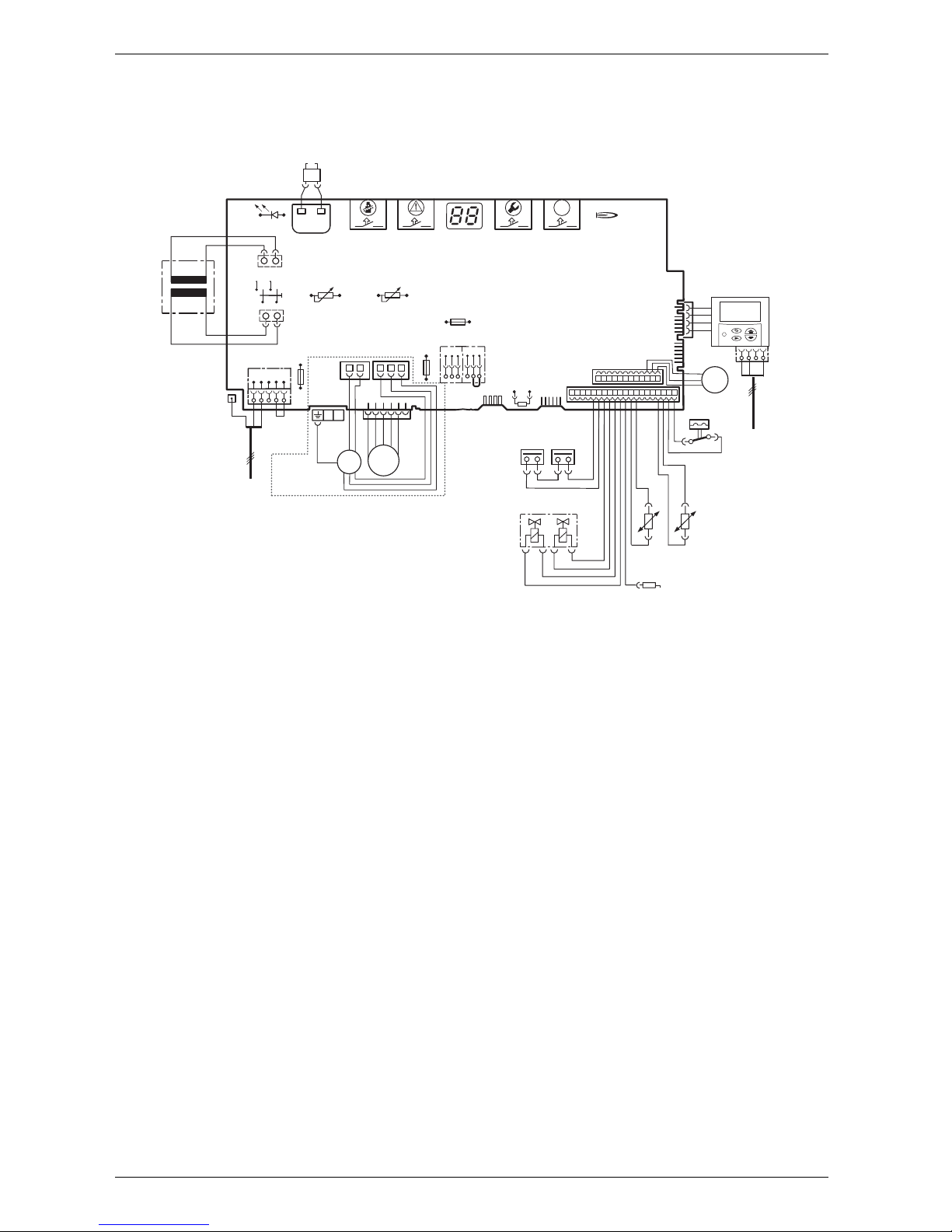
1.8 Electrical wiring diagram
Fig. 4
4.1 Ignition transformer
6 Temperature limiter, heat exchanger
6.1 Hot water NTC sensor
9 Flue gas temperature limiter
18 Pump
32 Flame sensing electrode
33 Ignition electrode
36 Temperature sensor in CH flow
52 Solenoid valve 1
52.1 Solenoid valve 2
56 Gas valve CE 427
61 Reset button
84 Motor, 3-way valve
96 M icroswitch, hydraulic switch
135 Master switch
136 Temperature control for CH flow
151 Fuse, slow 2.5 A, AC 230 V
153 Transformer
161 Link
226 Fan
300 Code plug
302 E arth connection
310 Temperature control for hot water
312 Fuse, slow T 1,6 A
313 Fuse, slow T 0,5 A
317 Digital display
328 Terminal block for AC 230 V Mains supply
328.1 Link
363 Indicator lamp for burner
364 Indicator lamp for power supply
365 “Chimney sweep” button
366 Service button
367 ECO button
400 Text display
422 Connecting TR2
6
9
32
33
36
52.1
52
56
61
230 V
135
25 V
230V/AC
153
136
151
1247
89
161
M
226
300
L
NLsNs
328
LR
302
310
312
313
317
363
364
365
366
ECO
367
4.1
328.1
6.1
18
84
96
M
400
43F
M
6 720 610 602 - 02.1O
mains supply
422
o - orange g - green bl - black r - red p - purple
r
r
bl
bl
bl
bl
bl
o
o
o
o
g
g
p
p
p
Page 9
6 720 611 447 GB (03.11)
Details of the appliance
9
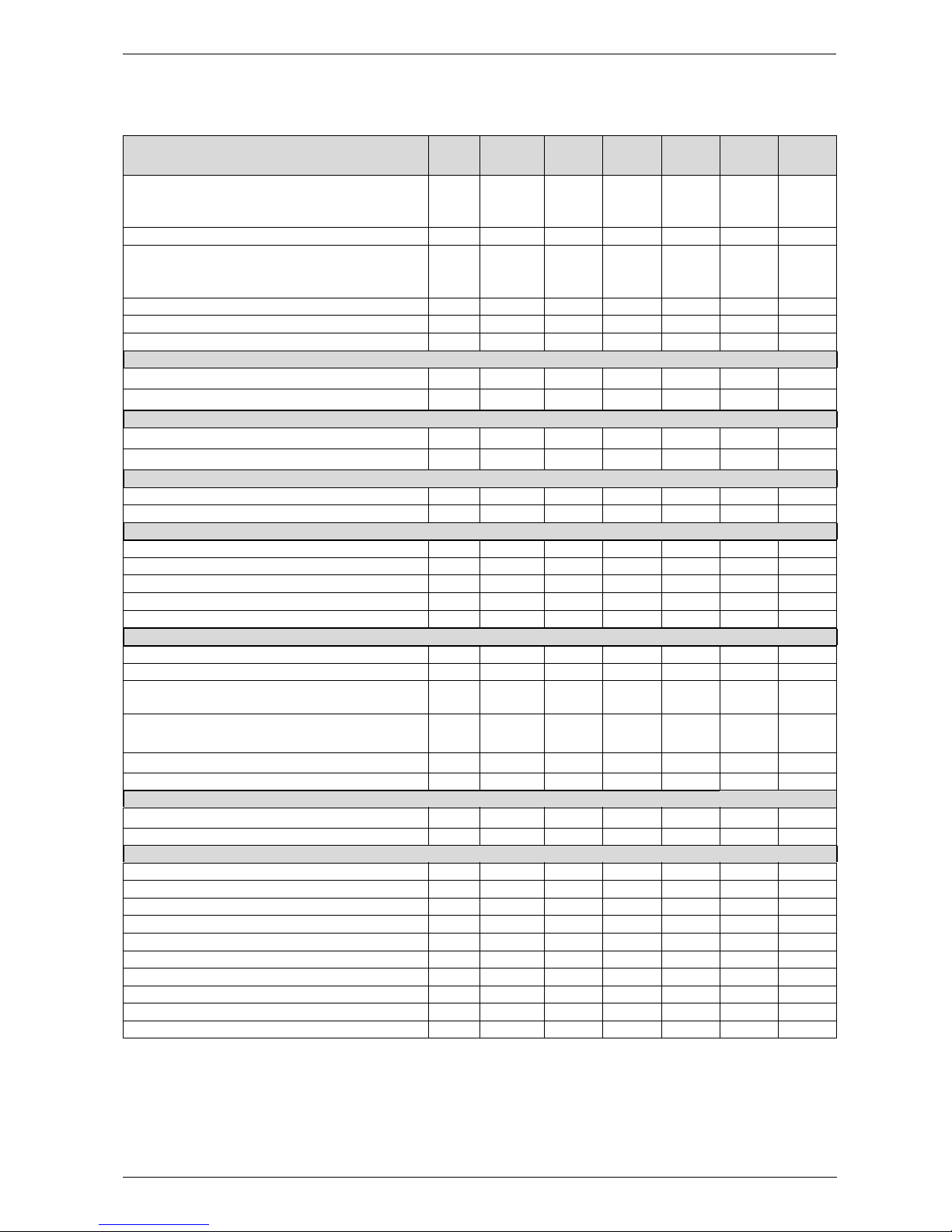
1.9 Technical data
Units
RD 532iNGRD 532i
Propane
RD 537iNGRD 537i
Propane
RD 542i NGRD 542i
Propane
Max. rated heat output net 40/30 °C central heating
Max. rated heat output net 50/30 °C central heating
Max. rated heat output net 80/60 °C central heating
kW
kW
kW
34.3
34.0
32.2
34.3
34.0
32.3
39.7
39.2
37.1
39.7
39.2
37.1
41.4 41.4
41.4 41.4
39.1 39.1
Max. rated heat input net kW 32.5 32.5 37.5 37.5 40.0 40.0
Min. rated heat output net 40/30°C
Min. rated heat output net 50/30°C
Min. rated heat output net 80/60°C
kW
kW
kW
8.4
8.3
7. 4
11. 6
11. 4
10 .5
12.9
12.8
11. 4
16. 2
16 .1
14 . 3
12.9 16.2
12.8 16.1
11.4 14.3
Min. rated heat input net kW 7.6 10.8 11.8 14.8 11.8 14.8
Max. rated heat output net, domestic hot water kW 32.2 32.2 37.1 37.1 39.1 39.1
Max. rated heat input net, domestic hot water kW 32.5 32.5 37.5 37.5 40 40
Maximum gas flow rate – After 10 minutes from lighting
Natural gas G20 (CVnet 34.02 MJ/m3)m
3
/h
3.4 3.9
4.2
LPG (CVnet 88 MJ/m
3
)
kg/h 2.5 2.7
Gas supply pressure
Natural gas G20 (CVnet 34.02 MJ/m3)
mbar 20 - 20 -
20 -
LPG (CVnet 88 MJ/m
3
)
mbar - 37 - 37
-37
Expansion vessel
Charge pressure bar 0.75 0.75 0.75 0.75 0.75 0.75
Total capacity l 10 10 10 10 10 10
Hot water specifications
Hot water flow rate @35°C rise l/min 12.5 12.5 14.5 14.5 15.5 15.5
Outlet temperature range °C 40 - 60 40 - 60 40 - 60 40 - 60 40 - 60 40 - 60
Max. permissible water supply pressure bar 10 10 10 10 10 10
Min. inlet pressure for maximum flow rate bar 1.2 1.2 1.2 1.2 1.2 1.2
Specific flow rate @ 30°C l/min 14.6 14.6 16.9 16.9 18.0 18.0
Flue
Flue gas temp. 80/60°C, rated/min. load °C 67/55 67/55 87/58 87/58 87/58 87/58
Flue gas temp. 40/30°C, rated/min. load °C 43/32 43/32 65/43 65/43 65/43 65/43
Residual delivery pressure (inc. pressure drop in air
intake duct)
Pa 80 80 100 100 100 100
CO
2
level at max. rated heat output
CO
2
level at min. rated heat output
%
%
9.2
8.8
10 .8
10.5
9.2
9.2
11. 0
11. 0
9.2
9.2
11.0
11.0
NO
x
-class 5 5 5 5
55
SEDBUK figure BandA AAAAA
Condensate
Max. condensation rate (tR = 30°C) l/h 2.8 2.8 3.2 3.2
3.5 3.5
pH-value, approx. pH 4.8 4.8 4.8 4.8 4.8 4.8
General Data
Electrical power supply voltage AC ... V 230 230 230 230 230 230
Frequency Hz50 5050505050
Max. power consumption W 130 130 162 162 183 183
Noise output level dB(A) 37 37 41 41 42 42
Appliance protection rating IP X4D X4D X4D X4D X4D X4D
Max. CH flow temperature °C nom. 90 nom. 90 nom. 90 nom. 90 nom. 90 nom.90
Max. permissible operating pressure (CH) bar 2.5 2.5 2.5 2.5 2.5 2.5
Permissible ambient temperatures °C 0 - 50 0 - 50 0 - 50 0 - 50 0 - 50 0 - 50
Nominal capacity of appliance l 3.75 3.75 3.75 3.75 3.75 3.75
Weight (excluding packaging) kg 46 46 46 46 46 46
Table 2
Page 10
6 720 611 447 GB (03.11)
10
Installation regulations
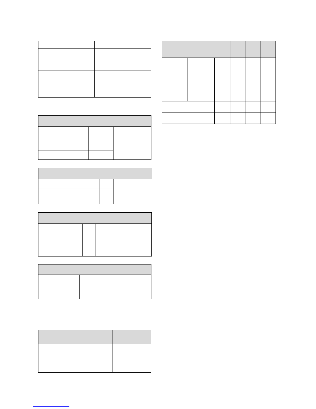
Condensate analysis, mg/l
Flue system
Elbow - 90 ° Equivalent length 2 m
Bend - 45 ° Equivalent length 1m
Gas supply
Domestic water performance
2 Installation regulations
Gas Safety (Installation & Use) Regulations 1998: All
gas appliances must be installed by a competent person. Failure to install correctly could lead to prosecution.
The manufacturers notes must not be taken, in any way,
as overriding statutory obligations.
The appliance must be installed in accordance with the
current IEE Wiring Regulations, local Building Regulations, Building Standards (Scotland) (Consolidation),
bye-laws of the local Water Company, Health and
Safety Document 635 (Electricity at Work Regulations
1989) and any other local requirements.
Product Liability regulations indicate that, in certain circumstances, the installer can be held responsible, not
only for mistakes on his part but also for damage resulting from the use of faulty materials. We advise the
installer to avoid any risk by using only quality approved
branded fittings.
The relevant British Standards should be followed i.e.
• BS 6798: Specification for the installation of gas
fired hot water boilers of rated input not exceeding
60kW
• BS 5449: Central Heating for Domestic Premises
• BS 5546: Installation of gas hot water supplies for
domestic purposes
• BS 5440:1: Flues and ventilation for gas appliances
of rated input not exceeding 70 kW (net): Flues
• BS 5440:2: Flues and ventilation for gas appliances
of rated input not exceeding 70 kW (net): Air
Supply
• BS 6891: Installation of low pressure gas pipework
installations up to 28mm (R1).
• BS 7074:1: Code of practice for domestic heating
and hot water supply
• BS 7671: Requirements for Electrical Installation.
These instructions must be followed.
Ammonium 1.2 Nickel 0.15
Lead ≤ 0.01 Mercury ≤ 0.0001
Cadmium ≤ 0.001 Sulphate 1
Chromium ≤ 0.005 Zinc ≤ 0.015
Halogenated
hydrocarbons ≤ 0.002
Tin ≤ 0.01
Hydrocarbons 0.015 Vanadium ≤ 0.001
Copper 0.028 pH-value 4.8
Table 3
HORIZONTAL 100 mm – Standard FLUE SYSTEM
Overall Diameter of Duct mm 100
Max. 4 m
(RD532i/537i)
Max 3.5m
(RD542i)
Flue Terminal / Duct
Assembly Length
mm 600
Extension Duct Length mm 1000
Table 4
HORIZONTAL 125 mm FLUE SYSTEM
Overall Diameter of Duct mm 125 Max. 13 m
(RD532i)
Max. 10m
(RD537i/542i)
Flue Terminal / Duct
Assembly
mm 1030
Table 5
VERTICAL 100mm FLUE SYSTEM
Overall Dia. of Duct mm 100 Excl. terminal:
Max. 6.4m
(RD532i/537i)
Max. 5.5m
(RD542i)
Flue Terminal / Duct
Assembly Length
mm 1140
Table 6
VERTICAL 125 mm FLUE SYSTEM
Overall Dia. of Duct mm 125 Excl. terminal: Max.
13.7 m (RD532i)
Max. 10.7 m
(RD537i/542i)
Flue Terminal / Duct
Assembly
mm 1365
Table 7
Total length of gas supply pipe
(metres)
Pipe diameter
(mm)
369
Gas discharge rate (m
3
/h)
8.7 5.8 4.6 22
18 .0 12 . 0 9 .4 2 8
Table 8
R 30 HER 35 HER 40
HE
Domestic
Water Flow
Rate l/min
Te mp e ra ture Rise
30 °C 14.2 17.0
19.2
Te mp e ra ture Rise
35 ° C 12 .1 14 . 6
16.4
Te mp e ra ture Rise
40 ° C 10 . 6 12 .8
14.4
Maximum Mains pressure bar 10.0 10.0
10
Minimum Mains pressure bar 0.2 0.2
0.2
Table 9
Page 11
6 720 611 447 GB (03.11)
Installation
11
3 Installation
3.1 Important remarks
B Appliance should only be installed in sealed central
heating and hot water systems.
B To avoid gas formation in the system, galvanised radi-
ators or pipes must not be used.
B If a room thermostat is used: do not fit a thermostatic
radiator valve on the radiator in the primary room.
B This appliance uses an automatically variable pump.
An auto-bypass must not be fitted.
B Add a suitable anti-freeze fluid to the water in the
central heating system.
Suitable products are available from Betz-Dearborn
Tel: 0151-4209563, Fernox Tel: 01799-550811
and Salamandor on 0121 378 0952.
B In our experience, the addition of sealing agents to
the water in the central heating system can cause
problems (deposits in the heat exchanger). For that
reason we advise against their use.
3.2 Domestic hot water
Any regulations specified by the local water company
must be observed.
The final 600 mm of the mains cold water connection to
the appliance should be made in copper tube only.
The appliance is suitable for a mains supply having a
maximum pressure of 10 bar. A pressure reducing valve
must be fitted, if necessary.
The hot water outlet temperature is set to be capable of
achieving a maximum of 60°C. The maximum temperature and the frequency of the recharge of the heat store
may be reset.
The water flow rate of 11.0 l/min (RD532i), 12.7 l/min
(RD537i) and 13.5 l/min (RD542i) will give a temperature rise of 40°C. If a higher rise is required then the
flow must be reduced at the tap and the discharge temperature will rise up to the maximum set figure.
The temperature rise, up to the maximum set by the
user, is automatically maintained by the modulation of
the heat input. In winter, when the mains temperature is
very low, the water flow, adjusted at the tap or shower,
should be reduced to maintain the required delivery
temperature.
It is suggested that long pipe runs to taps or showers
be insulated to prevent the rapid cooling of the water.
All types of single lever mixer taps and thermostatic
mixer units suitable for a mains pressure of up to 10 bar
can be used.
The head of a loose-head shower must not be allowed
to fall within 25 mm of the top the bath to prevent the
risk of water being drawn back into the mains. Alternatively the shower must be fitted with an anti-syphonage
device at the point of the flexible hose connections.
Over-rim bidets may be connected to the appliance provided that it is in accordance with the requirements of
the local water company. The outlet(s) should be
shrouded and unable to have any temporary hand held
spray attached. No anti-syphonage arrangements are
necessary.
In exceptionally hard water areas a device to prevent
scale formation may be fitted or, alternatively, the maximum temperature reset to about 45°C which may
reduce the risk of scale formation. The installation of a
scale inhibitor assembly should be in accordance with
the requirements of the local water company. Artificially
softened water must not be used to fill the central heating system. An isolating valve should be fitted to allow
for servicing.
Devices, such as water meters or back-flow prevention valves, capable of preventing the flow of
expansion water must not be fitted unless separate arrangements have been made.
A Zilmet Z160 expansion vessel is the preferred type. A
thread sealant compatible with potable water must be
used. The vessel should be connected into the cold
water mains inlet pipe as close as possible to the appliance.
3.3 Sealed systems
The appliance must not be operated without the system
being full of water, properly vented and pressurised.
The expansion vessel has a volume of 10 litres and is
charged to a pressure of 0.75 bar.
The water capacity of the system is shown in table 12,
page 31. If a greater capacity is required then an additional expansion vessel must be fitted into the system
return as close to the appliance as possible. The system
pressure can be set up to a maximum of 1.5 bar with
1 bar being the normal setting.
If the system pressure is greater than 2.5 bar when the
appliance is operating at maximum temperature then an
additional expansion vessel must be fitted into the system return as close to the appliance as possible.
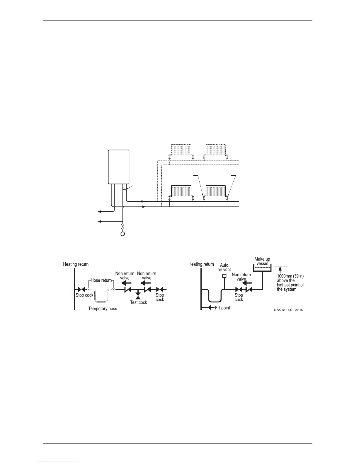
The filling point must be at low level and arranged as
shown in figs. 5 and 6.
The pressure relief valve is set to operate at 3 bar.
There must be no connection to the mains without the
approval of the local water company. All connections in
the system must be capable of withstanding a pressure
of up to 3 bar and the radiator valves conform to the
B Always turn off the gas cock before car-
rying out any work on components
which carry gas.
i
Fixing of the appliance, gas and flue connections, commissioning of the system
and electrical connections may only be
carried out by competent persons authorised by CORGI.
Page 12
6 720 611 447 GB (03.11)
12
Installation
requirements of BS2767:10.
Fit Thermostatic Radiator Valves to radiators in the
sleeping accommodation and not to the radiator where
the room thermostat is sited, this must be left open.
Repeated venting probably indicates a leak and this
must be rectified to ensure the proper operation of the
appliance.
No galvanised radiators or pipes must be used.
If any system water treatment is required then
only products suitable for use with Aluminium
shall be used i.e Fernox- Copal or Superconcentrate or Sentinal X100, in accordance with the
manufacturers instructions. The use of any other
substances will invalidate the guarantee. The pH
value of the system water must be less than 8 or
the appliance guarantee will be invalidated.
Suitable products are available from Betz-Dearborn Tel:
0151-4209563, Fernox Tel: 01799-550811 and Salamandor on 0121 378 0952.
A drain cock to BS2879 must be fitted to the lowest
point of the system.
IMPORTANT: Check that no dirt is left in the
water pipework as this could damage the appliance. Thoroughly flush the heating system and
the mains water supply before fitting the appliance to the wall in accordance with the recommendations of BS7593:1992.
Fig. 5 Sealed primary water system
Fig. 6
3.4 Siting the appliance
Regulations concerning the Installation Site
B Relevant national regulations must be complied with
section 3.9.1.
B Consult the installation instructions for details of min-
imum clearances required.
Combustion air
In order to prevent corrosion, the combustion air must
not contain any corrosive substances.
Substances classed as corrosion-promoting include
halogenated hydrocarbons which contain chlorine and
fluorine compounds and are contained in some solvents, paints, adhesives, aerosol propellants and household cleaners, for example.
Surface temperature
The max. surface temperature of the casing and the flue
is less than 85 °C.
This means that, no special safety precautions are
required with regard to flammable building materials
and fitted furniture. The specified clearances must be
maintained.
Cupboard/Compartment
The appliance can be installed in a cupboard/compartment need for airing clothes providing that the requirements of BS6798 and BS5440:2 are followed. The low
casing losses from the appliance eliminate the need for
ventilation openings in the compartment.
6 720 610 576 -09.3O
APPLIANCE
A drain cock should be fitted at the lowest point of the
heating circuit and the appliance
WRC
approved
filling loop
Domestic
hot water
BS stop valve
Fixed spindle type.
Water main
Refer to
Appliance
Water Flow
Diagram
Lockshield valve
Radiator valve
Central heating return
Central heating flow
Page 13
6 720 611 447 GB (03.11)
Installation
13
3.5 Wall mounting frame assembly
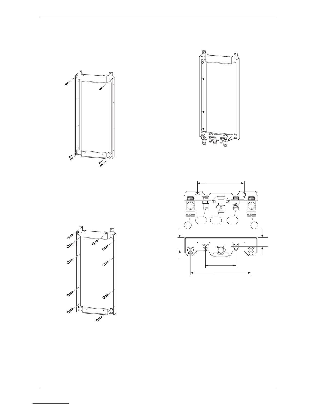
B Take the wall mounting frame out of the package and
screw together with 6 screws as shown in fig. 7. Use
the inner lugs on the top and bottom horizontal sections.
Fig. 7
B Hold the wall-mounting frame against the wall ensur-
ing that it is vertical.
B Mark the holes for the wall mounting frame onto the
wall, drill and plug the holes and screw the wall
mounting frame to the wall with the screws provided.
B Mark the position of the flue duct hole if a rear flue is
to be used. Refer to fig. 1 and 16.
Fig. 8
B Screw the pre-plumbing manifold with two screws to
the wall mounting frame.
Fig. 9
3.6 Pre-piping the system
Fig. 10 Manifold
43 CH flow
47 CH return
112 Gas cock
171 Domestic hot water
172 Cold water relief
B A drain tap should be fitted at the lowest point of the
central heating system.
B WRAS approved filling loop must be fitted.
6 720 610 597-06.1O
6 720 610 597-07.1O
6 720 610 597-08.1O
200
260
6 720 610 576-06.1O
35
120-130
50
4743
172112
171
Page 14
6 720 611 447 GB (03.11)
14
Installation
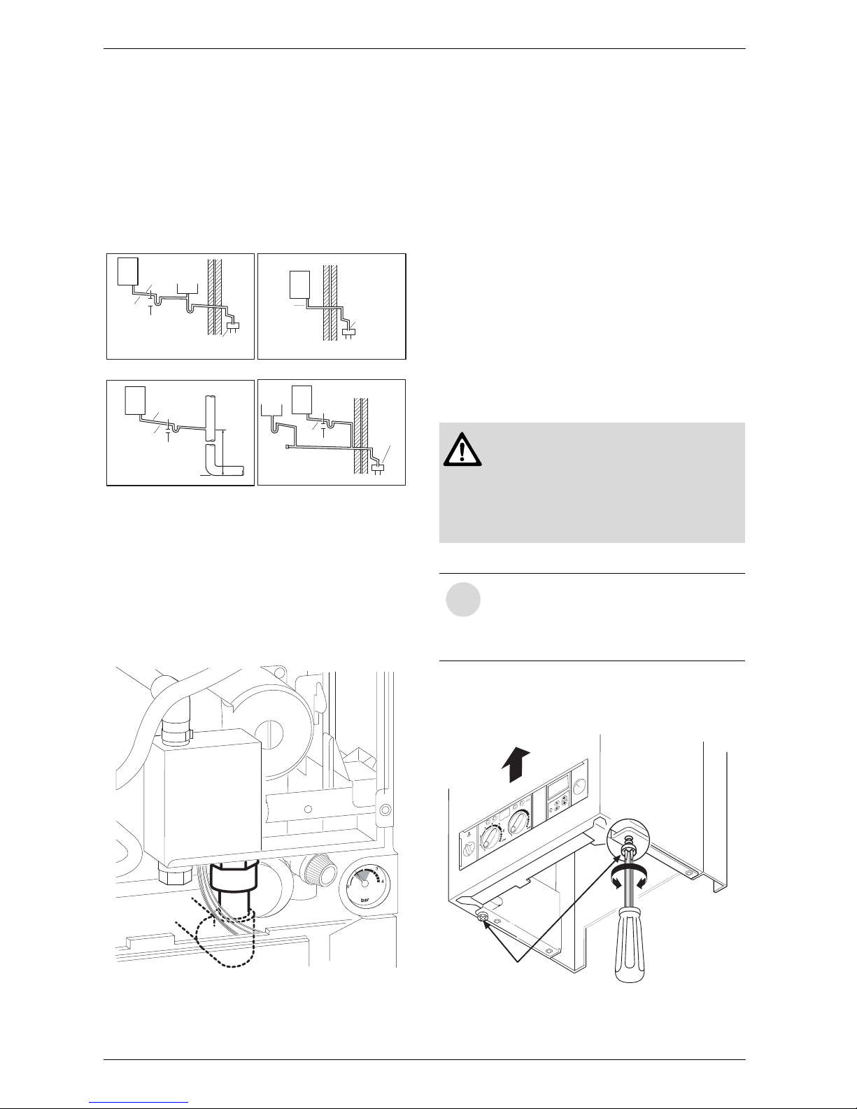
Condensate Termination and Route
The appliance has a built-in syphonic condensate trap
eliminating the need for external traps. Connect to the
22mm plastic drain pipe and extend the pipe run away
from the control panel and appliance witha constant fall
of 2.5° or 25mm in every metre. See Fig. 12
The condensate pipe can terminate into any of four
areas:
Fig. 11
Whilst all of the above methods are acceptable it is
always the best practice to terminate the condense pipe
via an internal waste system.This will eliminate the need
for any external condensate pipe runs which can be susceptible to freezing in extreme weather.
Fig. 12 Recommended route of the condensate drain
External condensate pipework
The syphonic condensate trap collects condensate into
a trap which releases it in 100 ml quantities. This helps
to prevent the discharge from freezing.
If there is no alternative and the condensate pipe has to
be externally run, the following should be considered:
• The pipe run should take the shortest practical route.
• The pipework should be insulated with weather
resistant insulation.
• The pipe should terminate as close as possible to the
ground or drain, whilst still allowing the condensate
to safely disperse. This would prevent wind blowing
up the pipe.
• The pipework should be installed with the minimum
of horizontal runs and with a downward slope of at
least 2.5 °.
3.7 Fitting the appliance
Removing the outer case
B Remove retaining screws (1), see Fig. 13.
B Slide the outer case upwards and forwards to
remove (2).
Fig. 13
Boiler
Boiler
Sink
Ø 22 min.
Ø 22 min.
Ø 22 min.
Ø 22 min.
Siphon
Siphon
75 min. trap
Invert
No length
restriction
No length
restriction
No length
restriction
Internal soil
and vent stack
The gradient of the discharge pipe
should be 2.5¡ (40 mm/m) minimum
The gradient of the discharge pipe
should be 2.5¡ (40 mm/m) minimum
The gradient of the discharge pipe
should be 2.5¡ (40 mm/m) minimum
An internal waste system
An external waste system
The rainwater system
An external purpose made soakaway
The gradient of the discharge pipe should be
2.5¡ (40 mm/m) minimum
Use waterproof pipe work
insulation in very exposed
positions
Open end of pipe
direct into gully,
below ground but
above water level.
Open end of pipe
direct into gully,
below ground but
above water level
Open end of pipe direct
into gully, below ground
but above water level
75 min. trap
450 min.
Siphon
75 min. trap
Boiler
6 720 610 596 -03.2TD
Boiler
Sink
6 720 610 602 - 04.1O
Benchmark: For optimum performance
after installation, this boiler and its associated central heating system must be
flushed in accordance with the guidelines given in BS5793:1992 “Treatment
of water in domestic hot water central
heating systems”.
i
The outer case is secured against unauthorised removal by a retaining bracket
(electrical safety) at the bottom left. Always secure the outer case with this
bracket again after refitting.
.
1
2
6 720 610 597 -10.T
D
Page 15
6 720 611 447 GB (03.11)
Installation
15
Fixing the appliance
B Fit the washers onto the gas and water connections.
B Lift the boiler onto the wall-mounting frame. The lugs
pass through the rectangular holes in the boiler back
panel.
B Take care not to disturb the washers on the connec-
tions.
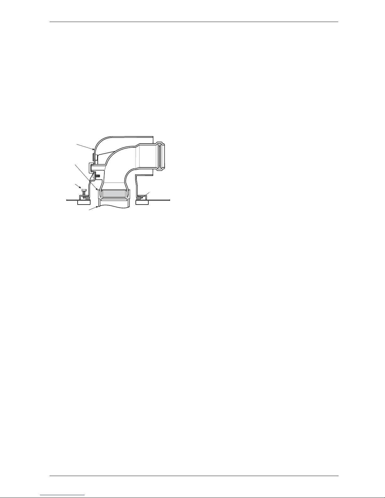
Connecting the flue duct
B Fit flue duct connector onto boiler flue socket.
B Secure with the screws supplied.
Fig. 14
B For remaining installation of flue assembly, refer to
the relevant installation instructions.
3.8 Checking the connections
Water connections
B Check that the O-rings or seals are in place before
tightening the connection.
B Turn on the service valves for central heating flow
and return and fill the heating system through a
WRAS approved filling loop.
B Check all seals and unions for leaks (testing pressure
max. 3.0 bar as indicated by pressure gauge).
B Turn on cold water service cock and fill hot water sys-
tem (testing pressure max. 10 bar).
B Check all connections for leaks.
Gas supply pipe
B Check that the seal is in place before tightening the
connection.
B Turn off gas cock to protect gas valve against dam-
age from excessive pressure.
B Check gas supply pipe.
B Release the pressure on the gas supply pipe.
3.9 Flue Systems
The only flue systems that may be used are those supplied with the boiler.
The flue system must be installed in accordance with
the requirements of BS5440:1.
Standard 100 mm flue system
The standard concentric flue system provides for a horizontal length of up to 4m (3.5m RD542i). Full instructions for fitting this flue are in Subsection 3.9.2
“Installation of the flue”.
Alternative 125 mm diameter flue systems
Installation instructions for the alternative flue systems
are sent with the appropriate flue kit.
Systems are available for a maximum horizontal length
of 13m (RD532i),10m (RD537i/542i).
A vertical flue system up to a height of 13.7 m (RD532i)
and10.7 m (RD537i/542i) is available.
45° and 90° flue bends can be used with a reduction in
flue length of 2 m for each 90° bend and 1 m for each
45° bend used.
IMPORTANT: Any horizontal flue system fitted to a
condensing boiler must incline from the appliance at an
angle of 3° (30 mm per metre length) to prevent condensate dripping from the flue terminal.
Note, the standard 100mm horizontal flue requires only
a 0.5° incline from the boiler as the inner exhaust pipe is
inclined at 2.5° inside the outer pipe.
This means that the clearance above the appli-
ance must be increased to match the duct length.
Refer to fig. 1 on page 5.
Retaining
Screw
Flue Turret to
Boiler Sealing
Gasket
Flue Turret
6 720 610 599 - 01.TD
Appliance
Flue Socket
Flue seal
Page 16
6 720 611 447 GB (03.11)
16
Installation
3.9.1 Siting the Flue Terminal
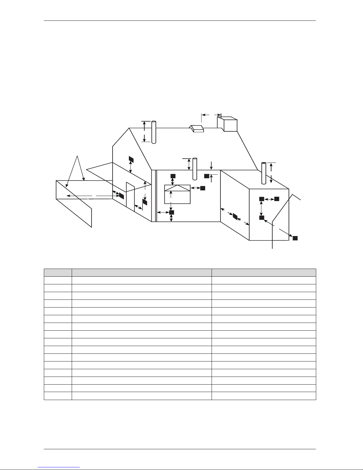
The flue must be installed in accordance with
BS 5440:1 and the Building Regulations. Flue terminals
in carports and under balconies are to be avoided.
The terminal must be positioned so that it does not
cause an obstruction nor the combustion products a
nuisance. See fig. 15 and table 10.
The terminal will, at times, give out a plume of water
vapour and consideration must be given to this when
choosing a terminal position. Keep clear of security
lighting, activated by passive infra-red sensing heads.
If the terminal is less than 2 m above a surface to which
people have access then a guard must be fitted. The
guard must be evenly spaced about the terminal with a
space of 50 mm in each direction and fixed with plated
screws.
A guard Type K6 for the standard horizontal flue, can be
obtained from Tower Flue Components, Vale Rise, Tonbridge TN9 1TB.
Fig. 15
Minimum dimensions of flue terminal positions (all types) (see fig. 15)
Q
Q
D,E
M
N
B
C
G
H
L
I
I
boundary
Q
K
H
H
A
F
J
P
Dimension Term inal position (kW input expressed in net) Balanced flues room sealed: Fanned draught
A
1)
Directly below an opening, air brick, opening windows, etc. 300 mm
B
1)
Above an opening, air brick, opening window, etc. 300 mm
C
1)
Horizontally to an opening, air brick, opening window, etc. 300 mm
D Below gutters, soil pipes or drain pipes 75 mm
E Below eaves 200 mm
F Below balconies or car port roof (lowest point) Not recommended
G From a vertical drain pipe or soil pipe 75 mm
H From an internal or external corner or to a boundary alongside the terminal 300 mm
I Above ground roof or balcony level 300 mm
J From a surface or boundary facing the terminal 1200 mm
K From a terminal facing the terminal 2000 mm
L From an opening in the car port (e. g. door, window) into the dwelling Not recommended
M Vertically from a terminal on the same wall 1500mm
N Horizontally from a terminal on the same wall 300 mm
P From a vertical structure on the roof 500 mm
Q Above intersection with roof 300 mm
Table 10
1) In addition, the terminal should not be nearer than 150 mm (fanned draught) to an opening in the building fabric formed for the purpose of accommodating a built-in element such as a window frame.
Page 17
6 720 611 447 GB (03.11)
Installation
17
3.9.2 Installation of the flue
The standard 100 mm diameter horizontal flue system is
suitable for lengths up to 4m (3.5m RD542i).
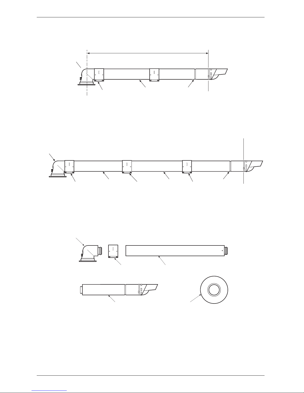
Flues up to 650 mm do not require an extension duct
assembly.
Flues between 1600 mm and 4000 mm (3500 mm
RD542i) require extension duct assemblies.
NOTE: Flue lengths between 650 mm and 730 mm
cannot be accommodated. Refer to fig. 17, 18, 19.
Standard 100m system comprise:
• Flue turret
• Flue turret clamp
• Terminal assembly
• Wall sealing gasket and cover plate.
Refer to fig. 20
Instructions for fitting other flue systems are packed
with the relevant flue kit.
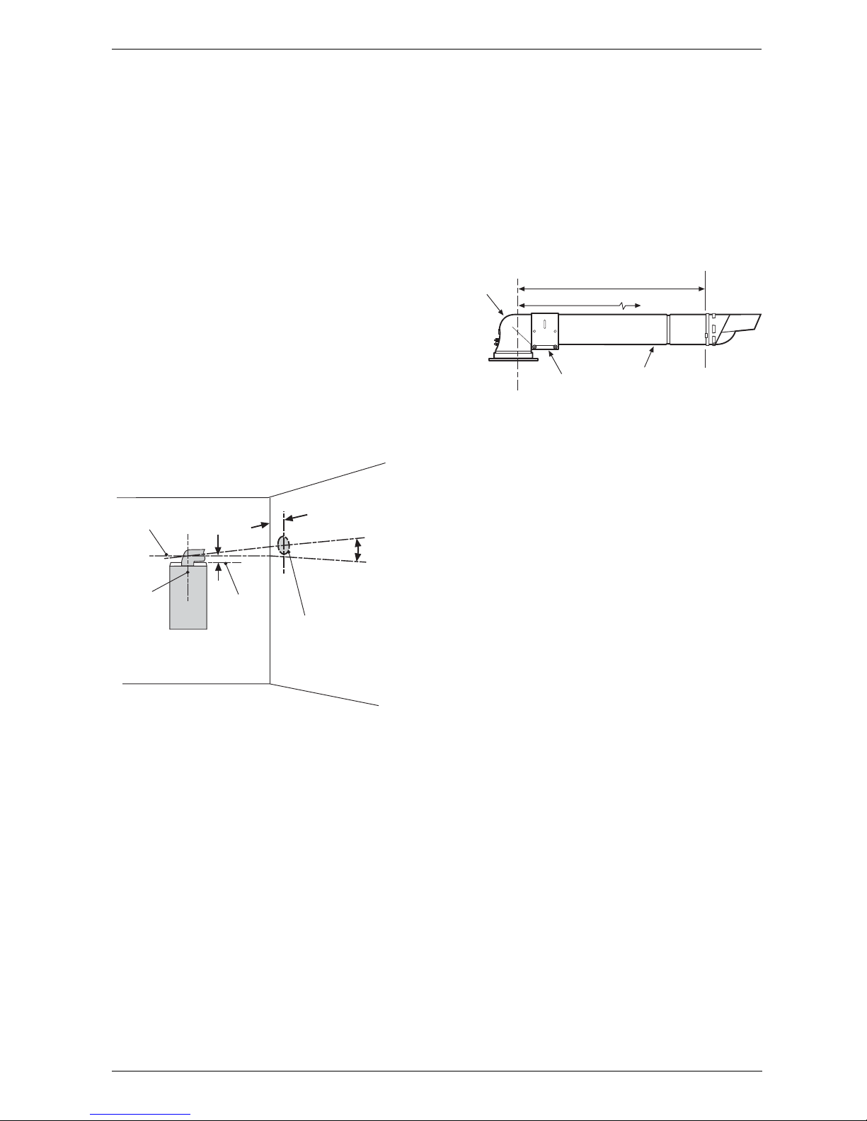
Check that the position chosen for the appliance is satisfactory. Refer to fig. 16.
Fig. 16 Marking the position of a side flue opening.
Note: ensure there is adequate access to the
air/flue sampling points in the flue turret.
Fig. 17 Standard Flue
Centre line of
flue/air duct
Centre
line of
flue
opening
and
appliance Drilling
point for
flue duct
opening
H = 40mm for the Standard 100mm Horizontal Flue
H = 70mm for the Optional 125mm Horizontal Flue
3°
(30mm/metre)
Standard 100mm
horizontal flue 0.5°
(5mm/metre)
Top of wall
mounting
frame (not
boiler)
Appliance
H
120
mm
6 720 610 602-08.3O
Maximum 650mm
Clamp
Flue
Turret
Terminal
Assembly
Outer
Wall
6 720 610 599 - 01.TD
Minimum 100mm
Page 18
6 720 611 447 GB (03.11)
18
Installation
Fig. 18 Flue with One Extension
Fig. 19 Flue with Extensions
Fig. 20 Flue Components
3.9.3 Flue duct preparation and assembly
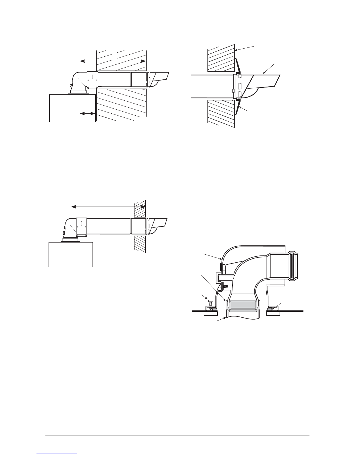
Measure the flue length L. Refer to fig. 21, 22.
Maximum 1600mm
Clamp
Flue
Turret
Terminal
Assembly
Outer
Wa l l
6 720 610 599 - 00.TD
Extension
Duct
Clamp
Flue
Turret
Terminal
Assembly
Outer
Wall
6 720 610 599 - 01.TD
Extension
Duct
Extension
Duct
ClampClamp
Clamp
Flue
Turret
Extension Flue Duct
Flue Terminal Wall Sealing Gasket
6 720 610 599 - 01.TD
Page 19
6 720 611 447 GB (03.11)
Installation
19
Fig. 21 Flue length - rear
Fig. 22 Flue length - side
Measure ‘L’ from the end of the metal section of the flue
terminal to the centre of the flue outlet on the boiler as
shown in Fig. 21 & Fig. 22 and deduct 90mm from that
measurement.
Cut both inner and outer flue pipe square at the opposite end to the terminal without creasing the tubes.
Remove any burrs before fitting the terminal to the turret.
Fig. 23 Flue terminal position
Assemble flue system completely. Push the ducts fully
together and clamp in the positions. The slope of the
terminal outlet must be directed as per Fig. 23.
The assembly will be made easier if a solvent free
grease is lightly applied i.e Silicone lubricant, to the
male end of the ducts.
NOTE: An inner wall sealing plate is provided
which should be fitted to the ducts before assembly.
Push the assembly through the wall and fix the turret to
the appliance with the screws provided. Refer to fig. 24.
Fig. 24 Flue turret
Ensure that the turret is fully secured to the socket on
the boiler.
If the terminal is within 2 m of the ground where there is
access then an approved terminal guard must be fitted.
The guard must give a clearance of at least 50 mm
around the terminal and fixed with corrosion resistant
screws.
L
120
6 720 610 599 - 01.TD
L
6 720 610 599 - 01.TD
6 720 610 599-00.TD
Outer Wall Face
Flue Terminal
Wall Sealing Gasket
Retaining
Screw
Flue Turret to
Boiler Sealing
Gasket
Flue Turret
6 720 610 599 - 01.TD
Appliance
Flue Socket
Flue seal
Page 20
6 720 611 447 GB (03.11)
20
Electrical connections
4 Electrical connections
B Allow mains cable to protrude at least 50 cm from
wall.
B To maintain the splash-proof (IP) design: cut the
cable grommet hole size to match the diameter of the
cable, see fig. 27.
B The appliance must be earthed.
B It must be possible to completely isolate the appli-
ance with at least 3mm contact separation in both
poles.
The wiring between the appliance and the electrical
supply shall comply with current IEE Wiring Regulations
(and any local regulations which apply) for fixed wiring
to a stationary appliance.
• Supply: 230 V ~ 50 Hz, 150 Watts
• External fuse 3 A
• The system connected to the boiler must NOT have
a separate electrical supply
• Water Protection IPX4D.
4.1 Connecting the appliance
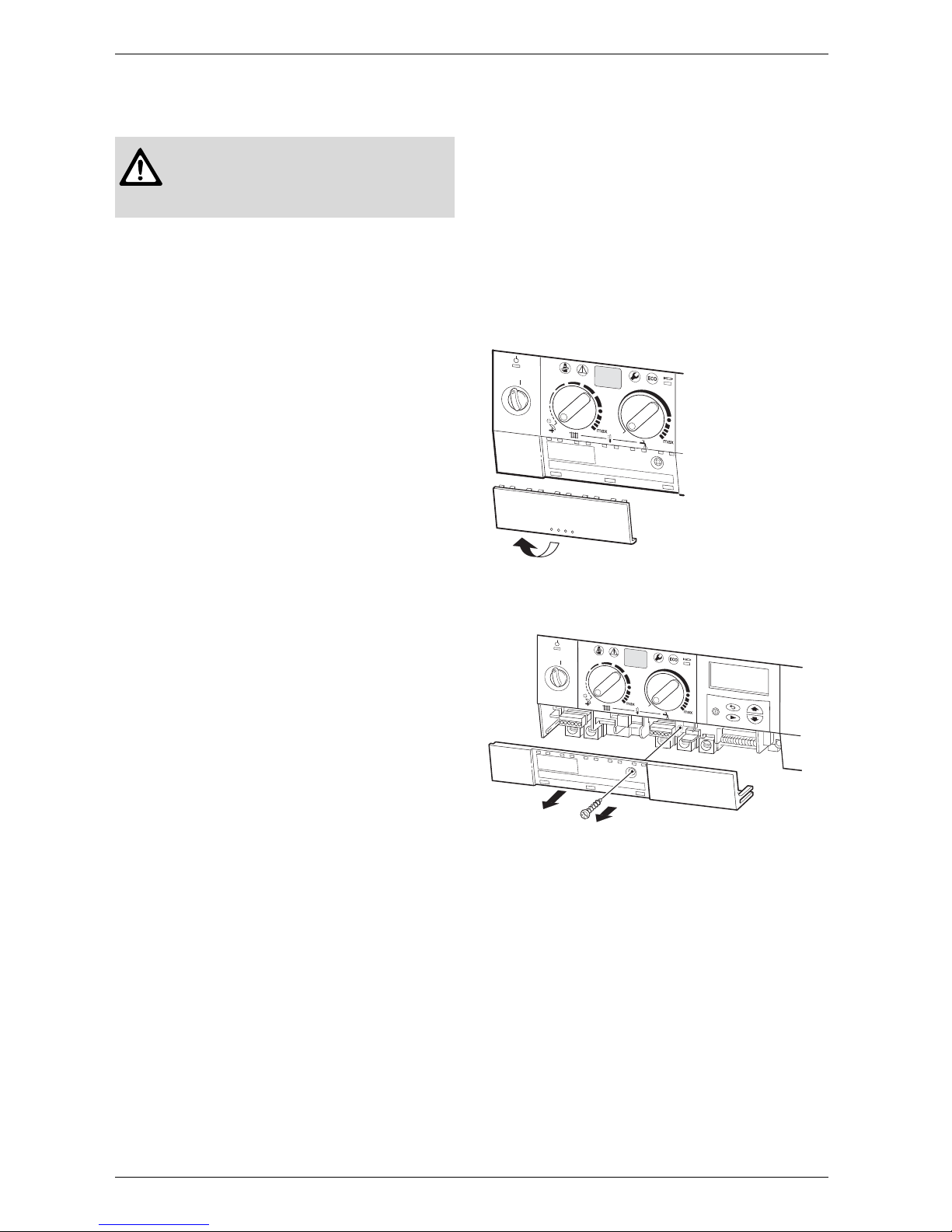
To gain access to the mains connection remove the
drop down facia cover. The drop down cover is
removed by lowering it to the horizontal position and
pushing firmly upwards at the rear of the supports to
release the cover. Lift cover from the appliance.
After installation (or in the event of an electrical fault) the
electrical system shall be checked for short circuits,
fuse failure, incorrect polarity of connections, earth continuity and resistance to earth.
B Pull out cover panel at the bottom and remove. Refer
to fig. 25.
Fig. 25
B Remove screw and slide terminal cover forwards to
remove. Refer to fig. 26.
Fig. 26
B Always disconnect the power supply to
the appliance at the mains before carrying out any work on the electrical systems and components.
0
1
2
3
4
5
E
6 720 610 332-10.1R
0
1
2
3
4
5
E
6 720 610 336 -18.1R
Page 21
6 720 611 447 GB (03.11)
Electrical connections
21
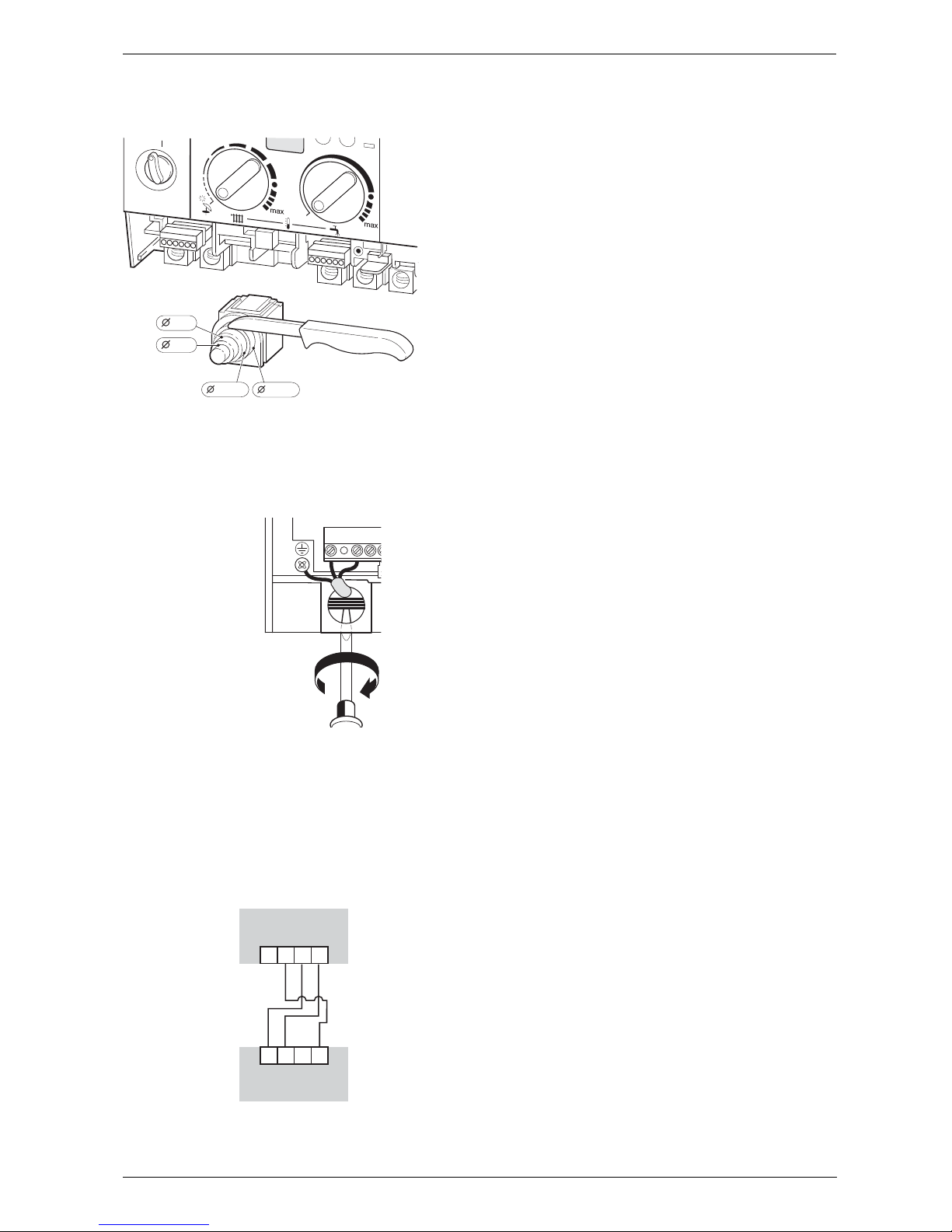
B Cut cable grommet to diameter of cable.
Fig. 27
B Feed cable through cable grommet and connect the
mains supply cable, see fig. 28.
B Secure cable in cable grommet by means of cable
grip.
Fig. 28
4.2 Connecting a TR2 Room Thermostat (accessory)
Connect the TR2 to terminals 3, 4 and F beneath the
Text display (page 8, fig. 4, item 422) using a minimum
1mm cable to avoid incresing resistance between the
terminals, see Fig. 29
Fig. 29
4.3 Mains Voltage external controls
connections
Externally wired controls are not required; the boiler has
a built-in text display programmer and frost protection.
The TR2 room thermostat provides additional frost protection and compliance to Part L of the Building Regulations.
0
1
2
3
4
5
E
6 720 610 332-12.1R
13-14
10-12
8-9
5-7
N
S
LN
L
TEXT DISPLAY
F34
4AF3
TR2
Page 22
6 720 611 447 GB (03.11)
22
Commissioning
5 Commissioning
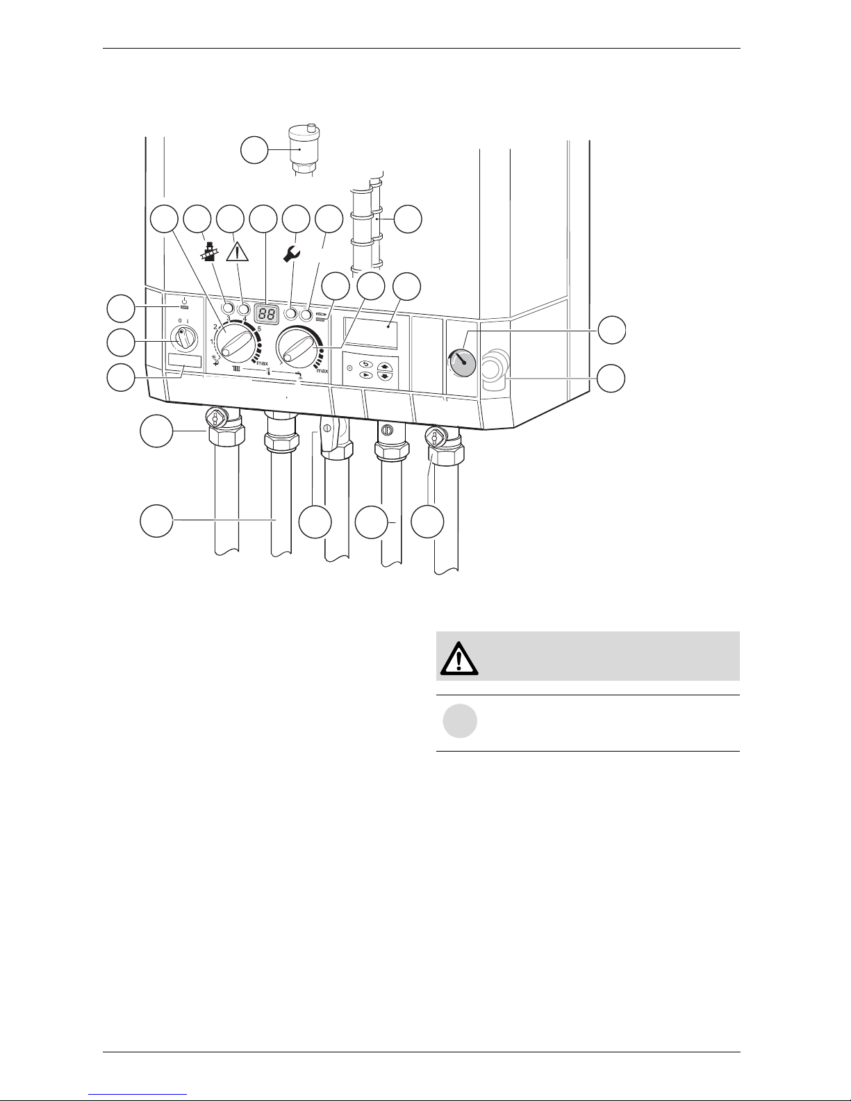
Fig. 30
8.1 Pressure gauge
15 Safety valve
27 Automatic vent
61 Reset button
135 Master switch
136 T emperature control for central heating
170 Service cocks on CH flow and return
171 Hot water
172 Gas cock (shown in off position)
173 Cold water service cock
295 Appliance type sticker
310 Temperature control for hot water
317 Multi function display
358 Condensation trap
363 Indicator lamp for burner
364 Indicator lamp for power supply
365 “Chimney sweep” button
366 Service button
367 ECO button
400 Text display
5.1 Commissioning
Benchmark Water Treatment: For optimum performance after installation, this boiler and its associated central heating system should be flushed in accordance
with the guidelines given in BS7593:1992 - Treatment
of water in domestic hot water systems. Full instructions
are supplied with proprietary cleansers sold for this purpose. If an inhibitor is to be used after flushing, it should
be used in accordance with the inhibitor manufacturers
instructions.
To drain the appliance shut the system valves and open
the system drain point.
Suitable flushing agents and inhibitors are available
from Betz-Dearborn Tel: 0151-4209563, Fernox Tel:
01799-550811 and Salamandor on 0121 378 0952.
Instructions for use are supplied with the these
products.
.
nn
ECO
364
135
295
E
8.1
365
61
317 366 367
310
136
363
400
15
27
358
6 720 610 597 - 05.1O
170
171
173
170
172
Never run the appliance when empty or
unpressurised.
i
The operational CO2 level is set at the factory and no adjustment is necessary when
installing a natural gas fired appliance.
Page 23
6 720 611 447 GB (03.11)
Commissioning
23
B Before commissioning, the gas supply pres-
sure must be checked at the gas supply pressure test point (see page 6, fig. 2, item 7).
Natural gas appliances must not be operated if
the gas supply pressure is below 18 mbar or
above 24 mbar. LPG appliances must not be
operated if the supply pressure is not 37 mbar
at the inlet to the appliance.
B Unscrew the condensation trap (358) and pull out, fill
with approx. 1/4 l of water and refit. Refer to fig. 30.
B Adjust charge pressure of expansion vessel to static
head of the central heating system (see page 31).
B Open all system radiator valves.
B Check automatic air vent is open, item 27, see fig 30
B Turn on service valves (170), fill central heating sys-
tem to pressure of 1 - 2 bar through the WRAS
approved filling loop. Refer to fig. 30.
B Vent radiators.
B Refill heating system and set the pressure to 1 bar.
B Turn on cold water service cock (173). Refer to
fig. 30.
B Check that the gas type specified on the identifica-
tion plate matches that of the gas supply.
B Turn on gas cock (172). Refer to fig. 30.
5.2 Switching the appliance on/off
Switching on
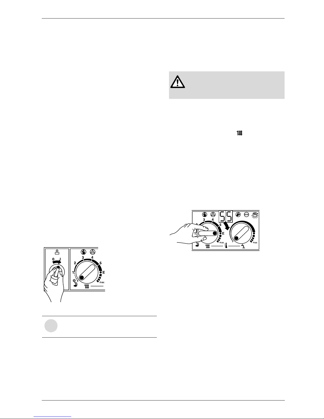
B Switch on the appliance at the master switch (I).
The indicator lamp shows green and the display will
show the central heating flow temperature, when the
appliance is operating in the central heating mode.
Fig. 31
The trap filling programme ensures that the condensation trap is filled after the appliance has been installed
or after the appliance has been out of use for a long
period or the mains supply has been interrupted. For
that reason, the appliance remains at minimum heating
output for 15 minutes.
Switching off the appliance
B Set the master switch to (0).
The green indicator lamp goes out. The optional timer
will continue running until the emergency supply is
exhausted.
5.3 Switching on the central heating
The central heating flow temperature is adjustable
between 35 °C and 88 °C. Refer to table 13, page 31.
B Turn the temperature control to set the flow tem-
perature to a level appropriate to the type of central
heating system:
– Underfloor heating: e.g. setting “3”
(approx. 50 °C)
– Low-temperature heating: setting “E”
(approx. 75 °C)
– Central heating systems for flow temperatures up
to 88 °C: limited “max” setting for low-temperature
operation (see page 31).
When the burner is alight, the red indicator lamp
lights up.
Fig. 32
5.4 System controls
B Set room temperature thermostat/controller (if fitted).
Refer to the instructions with the control.
B Set the thermostatic radiator valves to the desired
settings.
i
If the display alternates between -II- and
the central heating flow temperature, the
trap filling programme is active.
6 720 610 333-04.1O
B Always disconnect the appliance from
the power supply (fuse, circuit breaker)
before carrying out any work on the
electrical systems or components.
6 720 610 333-05.1O
Page 24
6 720 611 447 GB (03.11)
24
Commissioning
5.5 Setting the domestic hot water
temperature and flow rate
5.5.1 Domestic hot water temperature
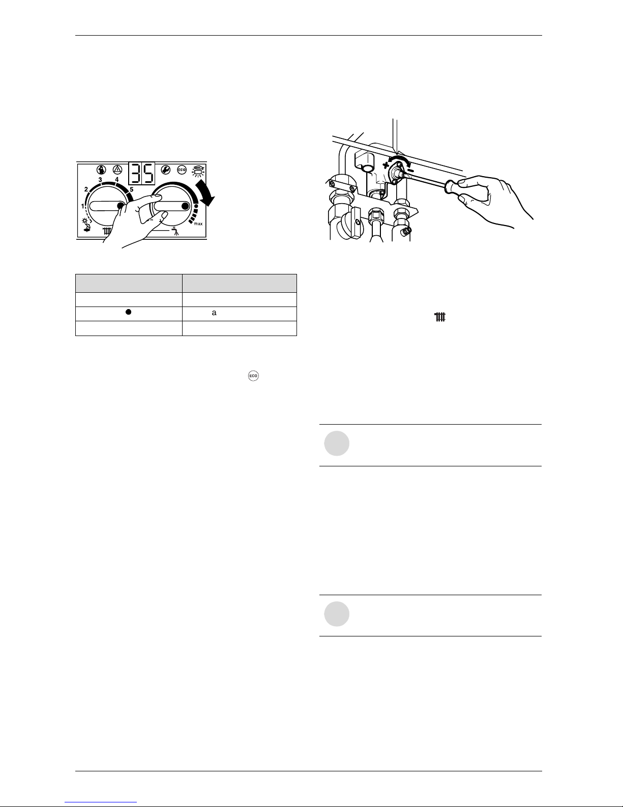
The hot water temperature can be set to between
approx. 40 °C and 60 °C.
This temperature is not shown on the display.
Fig. 33
“ECO” button
By pressing and holding the “ECO” button , until the
display lights, you can switch between Comfort mode
and Economy mode.
Comfort mode: button is not lit (factory setting)
The appliance is held constantly at the set temperature.
This means that hot water is available almost instantaneously at the tap. Consequently the appliance will
switch on at intervals, even if no hot water is being
drawn.
ECO mode with demand detection, button is lit
The demand detection function enables maximum gas
and water economy.
Briefly turning a hot water tap on and then off again signals demand to the appliance which then heats up the
water to the set temperature.
Hot water is thus available in about 1 minute.
ECO mode, button is lit
Water is not heated up until hot water is drawn. This
means that there is a longer waiting period before hot
water is available.
5.5.2 Hot water flow rate
Adjust the flow rate according to model.
Under standard conditions (2 bar) supply pressure, one
full turn is equivalent to approximately 2 l/min.
B To increase the flow rate:
turn screw on flow switch anti-clockwise (+).
The outlet temperature will decrease relative to the
increase in the flow rate.
B To reduce the flow rate (min. 8 l/min):
turn screw on flow switch clockwise (–).
The outlet temperature will increase relative to the
decrease in the flow rate.
Fig. 34
5.6 Summer mode (hot water only)
With room thermostat
B Turn temperature control on the appliance anti-
clockwise as far as the stop.
The central heating is now turned off. The hot water
function and the mains power supply for the heating
programmer and timer remain switched on.
5.7 Frost protection
B Leave master switch switched on.
If the appliance is to be left for long periods switch the
central heating off:
B Add a suitable anti-freeze fluid to the water in the
central heating system.
Suitable products are available from Betz-Dearborn
Tel: 0151-4209563 and Fernox Tel: 01799-
550811.
5.8 Pump anti-seize function
Every time the pump is switched off, (after a CH
demand) a timer is started. If after 24 hours the pump
has not run again, it is switched on for a period of 10
seconds.
Setting Hot Water temperature
Turn fully anti-clockwise approx. 40 °C
approx. 55°C
Turn fully clockwise approx. 60°C
Table 11
6 720 610 333-07.1O
i
Frost protection and constant frost protection modes can be set on the text display module.
i
This function prevents the central heating
pump seizing after long periods of inactivity.
6720 610 332-25.1O
Page 25
6 720 611 447 GB (03.11)
Commissioning
25
5.9 Fault Condition
In the unlikely event of a fault occuring while the appliance is in operation:
The display and the textdisplay then show a fault code
and the button may also flash.
If the button flashes:
B Press and hold the button until the display shows
“––”.
The appliance will then start up again and the display
will show the central heating flow temperature.
If the button does not flash:
B Switch the appliance off and then on again at the
master switch.
The appliance will start up again and the central heating flow temperature will be displayed.
5.10 Appliance Data Monitoring
If an external Gateway module is fitted then the
operating system must be commissioned at this
stage.
Commissioning of ADM and Gateway
Check if Gateway is plugged into the telephone line and
mains.
1. Remove the cover from the gateway.
2. Unplug the power connector from the side of the
gateway.
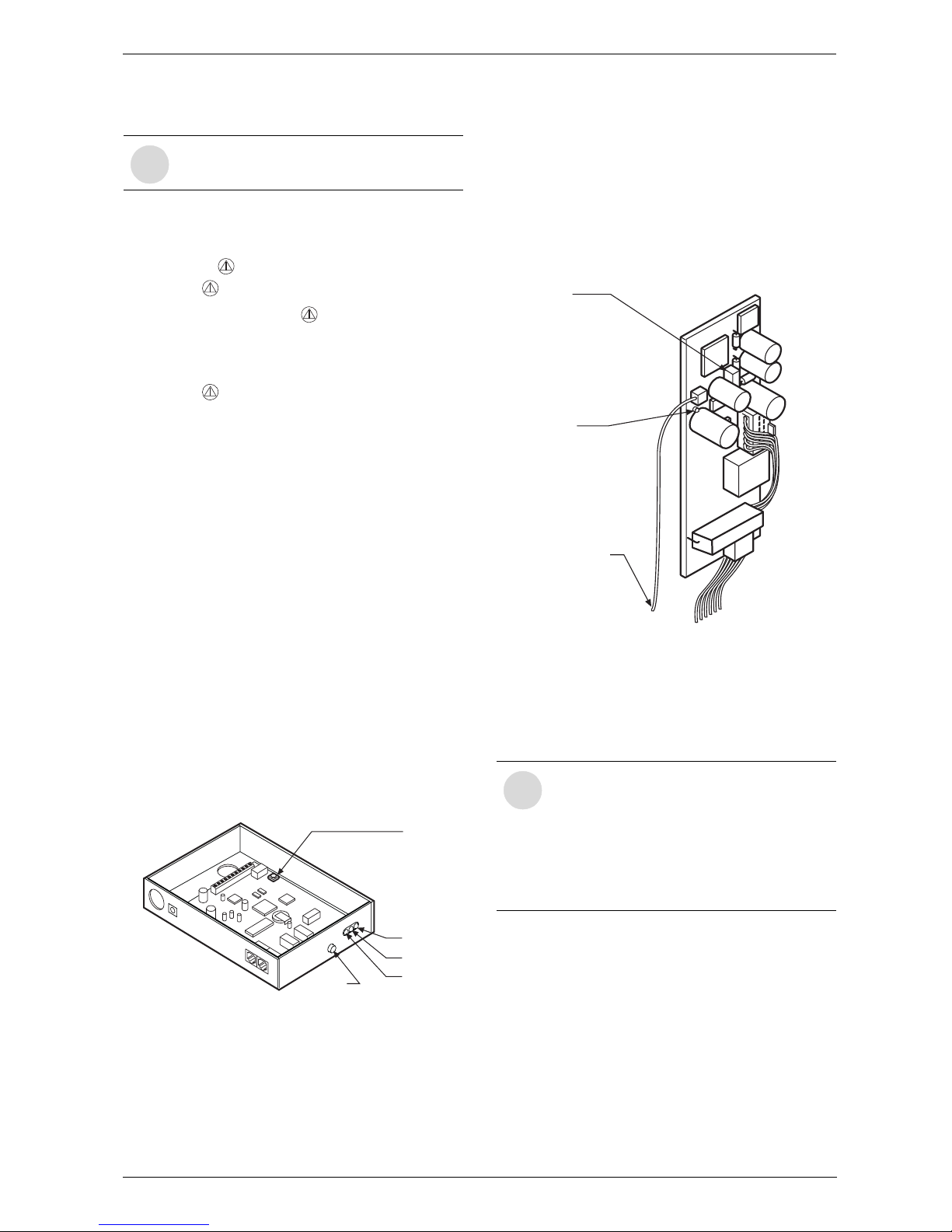
3. Reconnect the power to the gateway. Press and hold
SW1 and SW2 within 5 seconds of powering up,
see Fig. 35.
4. Observe 2 distinct clicks from the relays on the gateway.
Fig. 35 Gateway Module - switches and LED’s
5. Release the switches. Note only the RED LED is ON.
The Gateway is now reset.
6. Press SW1. Observe 0.5 Hz flashing of GREEN
LED. The gateway is now in “House Address Creation mode”. This lasts for approx. 1 minute.
7. Wait until GREEN LED flashes 3 seconds ON and 1
second OFF. The gateway has now Created the
House Address.
8. Make the jumper JP1 on the ADM while powering up
the appliance, see Fig. 36.
Observe LED on ADM flashing. The flashing rate is
0.5 Hz, the ADM is now in “House Address Acquisi-
tion mode”.
Fig. 36 ADM - switches and LED’s
9. Return to the gateway and press SW1. Observe
GREEN LED through the side of the box "House
Address Distribution mode”
10.After 100 seconds from step 8 observe ADM LED
flashing at 2 Hz.
11.After 60 seconds from step 9 observe GREEN LED
on gateway is ON.
12. The ADM will now cause the gateway to dial into
BG. A click of the relay will be heard from the gateway at each end of the dialling in.
13.Now power down the Heatronic, remove JP1,
replace all covers and power up again. The system is
now set up.
i
A list of faults that may occur is given on
page 46.
SW1
LED’s
Red
Yellow
Green
SW2
i
“House Address Acquisition mode” on the
ADM and “House Address Distribution
mode” on the gateway must overlap. Note
the times are as follows, the ADM will stay
in “House Address Acquisition mode” for
100 seconds and the gateway will stay in
and “House Address Distribution mode”
for 60 seconds.
JP1
LED
SENSOR
Page 26
6 720 611 447 GB (03.11)
26
Text Display
6Text Display
6.1 General Description
• The text display is used to display information about
the appliance and the system and to alter the settings
displayed.
• Once the appliance has been in operation for one
day, the text display module has a power buffer
period of about 10 hours during which it will run without the mains power supply. After that period has
elapsed, the clock function shuts down but all other
settings are retained.
6.2 Programming
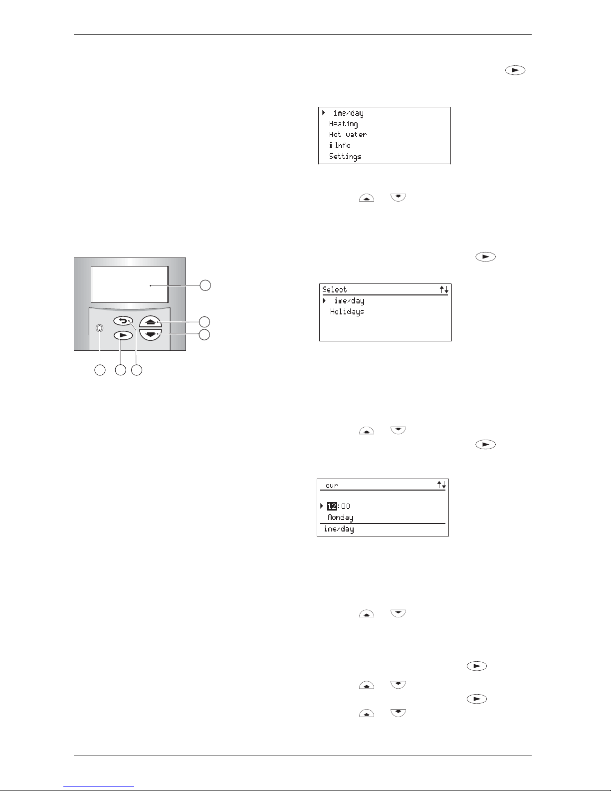
Fig. 37 Controls
a Display
b “Up”/“More” button
c “Down”/“Less” button
d “Back” button
e “Next” button
f “Delete” button
The standard display shows the following information:
•Time
• Room temperature (if TR 2 connected)
• CH flow temperature.
Additional indication if a special programme is active:
•x holidays
• Hot water immediately
• Constant on (comfort, if TR2 is not connected)
• Constant off (economy, if TR2 is not connected).
Other special operating modes may be displayed during commissioning, servicing, etc.
The programming procedure is described in detail
below using the clock function as an example:
B To start programming, press any button, e. g. .
The display lighting switches on and the main menu
is displayed:
Fig. 38 Main menu
B Use the or button to move the cursor
arrow on the left of the menu so that it points to the
desired menu item.
In this example, the cursor is positioned next to the
menu item Time/day/holidays.
B Confirm the selection by pressing the button.
The corresponding submenu is displayed:
Fig. 39 Submenu: Time/day
In the submenus, the top line indicates what action is
required.
The bottom line shows the previous menu level, if applicable (see fig. 40).
B Use the or button to select Time/day.
B Confirm the selection by pressing the button.
The corresponding submenu is displayed:
Fig. 40 Setting the hour
When settings are being entered, the setting to be
altered is indicated on the top line. In addition, the setting being altered is displayed with a dark background.
B Use the or button to set the hour.
– Press and release to change the display by one
unit at a time
– Press and hold to change the display rapidly
B Confirm the setting by pressing the button.
B Use the or button to set the minutes.
B Confirm the setting by pressing the button.
B Use the or button to set the day of the
week.
c
b
a
f
e
d
C
6 720 610 337-08.1R
6 720 610 598-04.2O
T
/holidays
6 720 610 598-05.2O
T
6 720 610 598-06.2O
T
H
Page 27
6 720 611 447 GB (03.11)
Text Display
27
B Press the button to confirm the setting. The
cursor then returns to the top line.
-or-
B Press the button to confirm the setting and
return to the previous menu (fig. 39 page 26).
-or-
B Do not press any other buttons for 15 minutes.
6.2.1 Deleting a setting
Either overwrite the setting or press the button to
delete it.
B Find the setting to be deleted.
B Press and release the button.
The display shows --:--
6.2.2 Resetting all parameters to their original
settings
B Press and hold the button for more than 15 sec-
onds.
After about 5 seconds, the following message
appears on the display:
ATTENTION
Delete all parameters
in x seconds
Once the reset has been completed, the following
message is displayed:
Please wait... Initialising
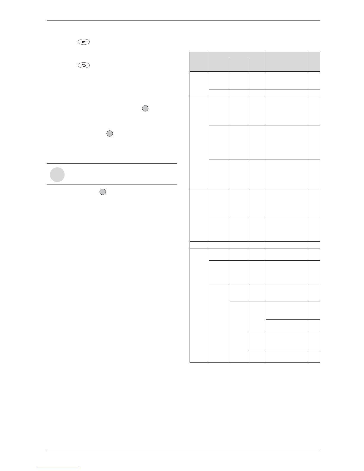
6.3 Menu structure
i
The hours of service can not be reset to 0.
C
C
C
Submenu
Main
menu
1. 2. 3.
Parameters to
change/select
Page
Time/
day/holidays
Time/day--- Hours
- Minutes
- Day of week
28
Holidays--Days holiday 28
Heating Heating
program
--- Day
- 1st operating mode
- 1st switching point
...
- 6th switching point
28
Set economy
temp.
(if TR2 is
connected)
--5...30°C 29
Manual
(if TR2 is
not connected)
- - - Automatic
- Constant on
(comfort)
- Constant off
(economy)
29
Hot
water
Hot
water
program
--- Day
- 1st operating mode
- 1st switching point
...
- 6th switching point
29
Hot
water
immediately
--Off/On 29
Info- --- 29
Settings Heating - - Optimum Start Off/On30
Hot
water
(ZSBRmodels)
--Only charging times/
times and temperatures
29
Service Display
service
param.
-- 30
Further
options
Language
-English/
-Français/
-Deutsch
30
-Time correction
-LCD contrast
30
30
Operating
times
-30
Fault
history
-30
Page 28
6 720 611 447 GB (03.11)
28
Text Display
6.4 Setting the time/day
6.4.1 Setting the time and day
For details of how to set the time and day, refer to
page 26.
6.4.2 Holidays
In the Holiday programme, the central heating runs in
Economy mode and the hot water is switched off (frost
protection function remains active).
B From the main menu, select Time/day/holidays,
and from the first submenu select Holidays.
B Enter the number of days holiday by pressing or
(max. 99 days holiday).
After the set number of days, the text display module
automatically cancels Economy mode at midnight on
the last day and returns to Automatic mode.
To cancel Holiday mode early:
B In the Holidays submenu:
Press the button until the display shows 0 .
6.5 Heating
6.5.1 Heating programme
Comfort Mode:
• With TR2 Room thermostat fitted:
Central heating is on. House will be heated to temperature set on TR2.
• Without TR2 Room thermostat fitted:
Central heating is on. Primary water is heated to temperature set at (radiator symbol) dial.
Economy Mode:
• With TR2 Room thermostat fitted:
Central heating is on. House will be heated to temperature set on ‘’Economy mode’’ of Text Display.
• Without TR2 Room thermostat fitted:
Central heating will be off.
Frost protection:
Central heating is off. Boiler will only fire if sensor registers temperatures below 5°C.
Basic setting (Automatic mode)
• The appliance switches automatically between normal heating, Economy mode and Frost protection
mode according to the timer settings entered.
•Basic setting:
– Heating (Comfort)starts at 6:00 am
– Economy starts at 10:00 pm
Setting options
• Maximum of six switching points per day with three
different operating modes (Comfort, Economy, Frost
protection).
• Same times for Monday to Friday.
• Same times for Saturday and Sunday.
• Different times for every day.
Setting switching times and operating mode
B From the main menu select Heating and then from
the first submenu, select Heating program.
B Select Monday - Friday, Saturday and Sunday or
an individual day of the week.
– Monday - Friday: to have “Comfort” and “Econ-
omy” or “Frost protection” switching on at the
same times every weekday.
– Saturday - Sunday: to have “Comfort” and
“Economy” or “Frost protection” switching on at
the same times Saturday and Sunday.
– Individual day of the week (e. g. Thursday): to
have the relevant program always switching on at
the specified time on that day of the week, i.e.
“Comfort”, “Economy” or “Frost protection” at the
same time every Thursday.
B Press . The display shows Set 1. operating
mode.
B Set the desired first operating mode (Comfort, Econ-
omy or Frost protection).
B Press . The display shows Set 1. time period.
B Set the desired first time period.
B Press . Set the following operating modes and
time periods as described for the first.
B If necessary: select the next day and enter the oper-
ating modes and timer periods as described above.
Timer periods and operating modes are you do not wish
to change can be skipped by pressing .
i
Changing winter and summer time:
B Only adjust the clock! Do not alter the
switching points (for heating, economy, etc.).
i
The day on which you enter the days holiday
counts as the first day of the holiday, i.e. the
unit starts the holiday program immediately.
Only include the day on which you are returning if you don’t want the heating to return to
the normal program on that day!
C
i
If the settings for a particular day of the
week are different from the settings for the
other days, then if Monday - Friday or
Saturday and Sunday is selected, the
display shows
--:--, i.e. there are no common switching
points for those options.
Page 29
6 720 611 447 GB (03.11)
Text Display
29
6.5.2 Setting the Economy temperature (if TR2
is connected)
This option allows you to set the room temperature for
Economy mode (Off (Economy)).
This function is only active if:
• Automatic mode or Economy mode is set on the TR2
room thermostat.
B From the main menu, select Heating and then from
the first submenu, select Set Economy temp..
B Use the or button to set a temperature
between 5 and 30 °C.
6.5.3 Manual operating mode (if TR2 is not connected)
For selecting an operating mode that is different from
the one set in the heating programme (Automatic
mode).
• You can choose between Automatic, Constant on
(comfort) and Constant off (economy).
• The manually selected operating mode starts imme-
diately.
• Constant off (economy) and Constant on (comfort)
are automatically reset at 00.00 (midnight).
• To cancel the manually selected operating mode:
– select the relevant menu and then press the
button,
– or select a different operating mode,
–or set Holiday.
B From the main menu select Heating and then from
the first submenu Manual select required mode.
6.6 Hot water
General description
• Combi models only: The basic settings provide a
straightforward timer programme:
enabling Hot Water pre-heat from 5:00am
disabling Hot Water preheat from 10:00pm.
The ECO button must not be lit.
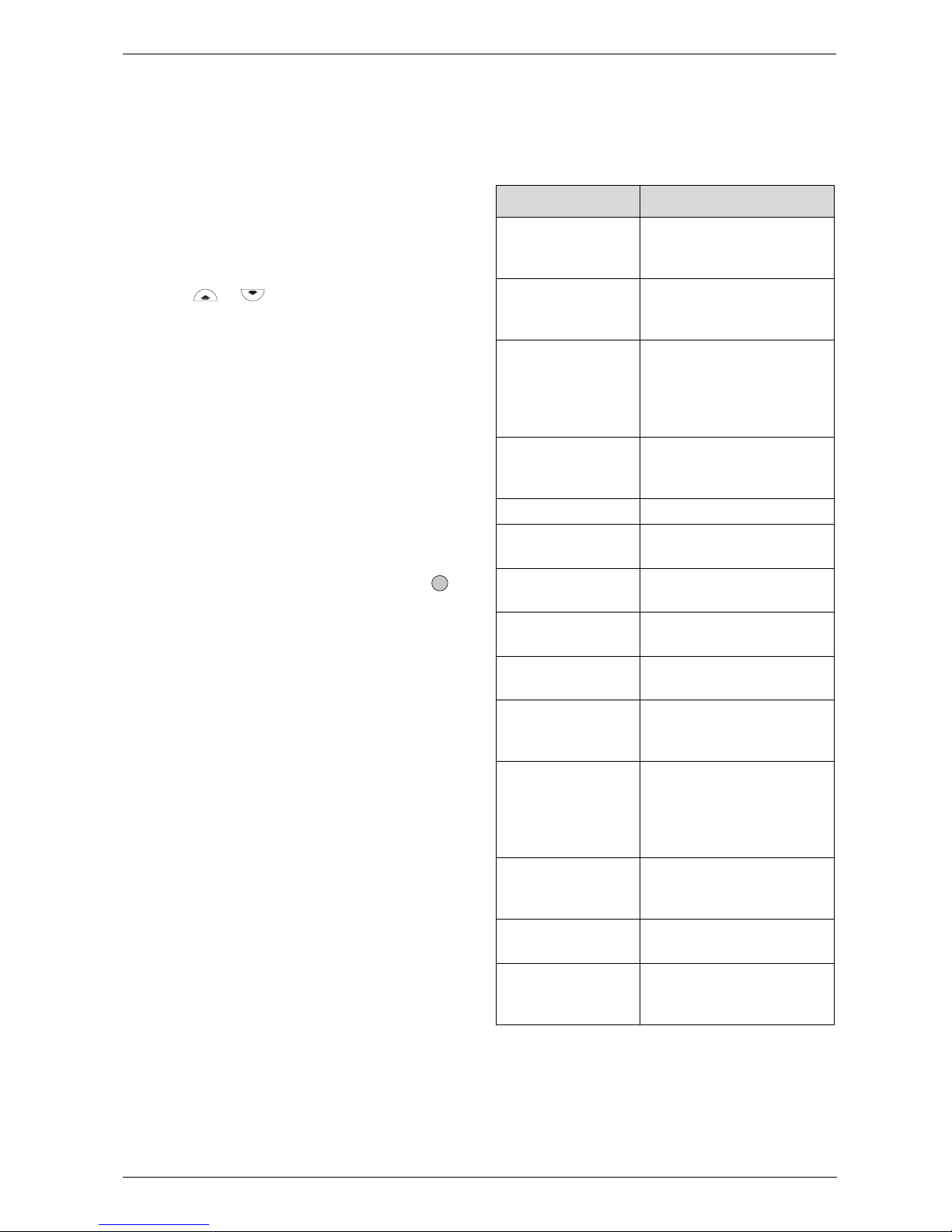
6.7 i Info
B Select Info from the main menu.
You can view the following information:
C
Display text Description
Room temperature
(if TR 2 connected)
Current temperature in the
room where TR 2 is installed
Required room
temperature
(if TR 2 connected)
Required temperature in
room where TR 2 is installed
Operating mode
(if TR 2 connected)
E. g. Heating, Economy in
Automatic mode
or
Economy, Heating, Frost
protection in manual mode
Max. flow temp. Maximum CH flow tempera-
ture set on the temperature
control for CH flow
Actual flow temp. Actual CH flow temperature
Required flow
temp.
Required CH flow temperature
Max HW temp. Maximum permissible hot
water outflow temperature
Required HW
temp.
Required hot water temperature
Actual HW temp. Actual hot water outflow
temperature
Storage Tank
charge released
or blocked
Shows, if hot water is
released or blocked
Storage Tank
charge on or off
or Storage Tank
charge
afterrunning
Shows, if hot water is on or
off, or if the pump for the
Storage Tank afterrunning is
on
Boiler operat.
mode
winter/ summer
Indicates which mode the
CH flow temperature control
is set to
Burner on/off Indicates whether the burner
is alight or not
Pump on/off Indicates whether the inte-
gral pump is switched on or
off
Page 30
6 720 611 447 GB (03.11)
30
Text Display
6.8 Settings
6.8.1 Heating (if TR 2 is connected)
Optimum Start
If the optimum start facility is used:
Set the heating ON time to 1 hour before the house
needs to be at the required temperature.
The boiler will start in heating mode at the optimum
time, which could be at any time during that hour.
B From the main menu, select Settings and from the
first submenu, select Heating.
B Press or to switch Optimum Start on or off.
Basic setting: “ON”
6.8.2 Hot Water (Storage Tank, system models
only)
The text display can control the hot water either with
Times and temperatures or only times.
• Times and temperatures: One can choose up to
six different times with temperatures, see page 29
“Hot water”.
• Only times: During that times the Storage Tank will
be charged to the chosen temperature.
B From the main menu, select Settings and from the
first submenu select hot water.
B Press or to switch Times and temperatures
or only times.
6.8.3 Service
Displaying service functions
This option displays various current settings and statuses of the electrically controlled appliance and system
components for the benefit of the heating engineer.
Service parameters
Language
Available languages are: English, Français (French),
Deutsch (German).
B From the main menu, select Settings, from the first
submenu select Service, from the Second submenu
select Further options, and from the third submenu
select Language.
B Press or to select the desired language.
Two other supplementary functions can be selected
from the third submenu Language:
• Time correction
•LCD contrast.
Time correction:
B Press and hold the button (about 5 seconds)
until the display shows Time correction and LCD
contrast.
B Press or to select Time correction.
B Press the button. The display shows Change
value.
B Press or to set the number of seconds in
24 hours.
Basic setting: “+ 0 s”
LCD contrast:
B Press and hold the button (about 5 seconds)
until the display shows Time correction and LCD
contrast.
B Press or to select LCD contrast.
B Press the button. The display shows Change
value.
B Press or to adjust the LCD contrast.
Basic setting: e. g. “47”
Operating times
This option shows the hours of service (appliance,
burner and hot water) since commissioning.
B From the main menu, select Settings, from the first
submenu select Service, from the Second submenu
select Further options, and from the third submenu
select Operating times.
Fault history
This option displays any faults that have occurred for
the information of the service engineer. The first fault
displayed may still be active. Any other faults displayed
are no longer active.
B From the main menu, select Settings, from the first
submenu select Service, from the Second submenu
select Further options, and from the third submenu
select Fault history.
6.9 Individual timer programmes
Tables for your own timer programmes you find in the
User Manual.
i
Turn the hot water temperature control
always higher than the temperature at the
text display is chosen.
Page 31
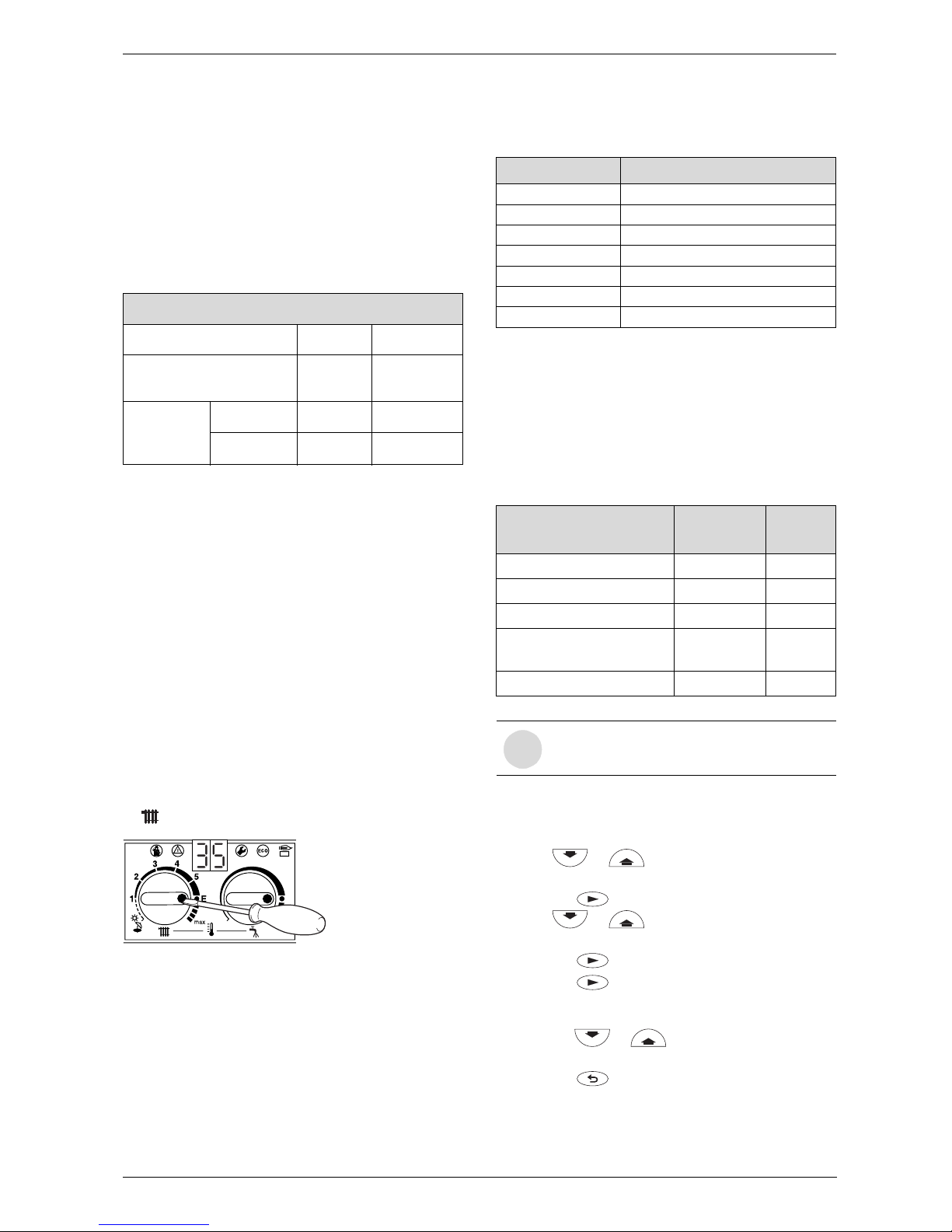
6 720 611 447 GB (03.11)
Individual settings
31
7 Individual settings
7.1 Mechanical settings
7.1.1 Checking the size of the expansion vessel
Maximum pressure at maximum CH flow temperature is
2.5 bar. If the pressure is greater than this then fit an
extra expansion vessel. Refer to table 12.
System Capacity – BS7074:1
7.1.2 Setting the central heating flow temperature
The central heating flow temperature can be set to
between 35 °C and 88°C.
Limited maximum setting for low-temperature
operation
The temperature control is factory limited to setting E,
giving a maximum flow temperature of 75°C.
Adjustment of the heating output to the calculated heat
demand is not required by the heating systems regulations.
Removing the maximum setting limit
For heating systems which require higher flow temperatures, the maximum setting limit can be removed.
B Lift off the yellow button on the temperature control
with a screwdriver.
Fig. 41
B Rotate yellow button through 180° and replace (dot
facing inwards).
The CH flow temperature is no longer limited.
7.2 Settings on the Bosch Heatronic
7.2.1 General description
The text display module provides a convenient means of
setting various appliance functions.
This description is limited to those functions necessary
for commissioning.
Displaying service functions
All service functions are displayed.
B Press any button to activate the main menu.
B Press or button until the arrow cursor is
pointing to Settings.
B Press the button.
B Press or button until the arrow cursor is
pointing to Service.
B Press the button.
B Press the button to select Display service
parameters.
Service function 0.0, Last fault is displayed.
B Press the or button to cycle through the
current settings.
B Press the button to exit the menu.
Expansion Vessel Pressure and System Capacity
Expansion Vessel litres 10
Expansion Vessel Charge
Pressure
bar 0.75
System
pressure and
capacity
1 bar litres 82
1.5 bar litres 46
Table 12
6 720 610 332-27.1O
Control setting CH flow temperature
1approx. 35°C
2approx. 43°C
3approx. 51°C
4approx. 59°C
5approx. 67°C
E approx. 75 °C
max approx. 88°C
Table 13
Service function Code no.
see
page
Anti-cycle time 2.4 32
Max. CH flow temp. 2.5 32
Max. heating output 5.0 32
Constant hot water cycletime
6.8 32
Variable pump settings 7. 0 32
Table 14
i
For a detailed description, refer to Service
Booklet for the Engineer 7 181 465 347.
Page 32
6 720 611 447 GB (03.11)
32
Individual settings
Setting service functions
Only the service functions that can be set are displayed.
B Press any button to activate the main menu.
B Press or button until the arrow cursor is
pointing to Settings.
B Press the button.
B Press oder button until the arrow cursor
is pointing to Service.
B Press the button.
The cursor is pointing to Display service parame-
ters.
B Press and hold the button (for about 5 sec-
onds) until the display shows Adjust service
parameters and the first service function to be set,
e.g. 2.0, Operating mode. If a fault has occurred,
the display will show 0.0 and the last fault.
B Press the or button until the desired
service function is displayed.
B Press the button.
The first line of the display shows Change value.
B Use the or buttons to enter the required
setting.
B Press the button.
The text display shows ATTENTION Store set-
tings?.
B Press or to select yes or no.
B Press to confirm your selection.
The text display shows Please wait ... ..., and the
service function is then displayed with the new setting.
B Press the or button until the next func-
tion you wish to change is displayed.
-or-
B Press the button to exit the menu.
7.2.2 Setting the anti-cycle time
(Service Function 2.4)
This service function is only active if Service Function
2.7, automatic anti-cycle time, is deactivated.
The anti-cycle time can be set to between 0 and 15 minutes (is factory set to 3 minutes).
If the setting 0 is entered, the anti-cycle time is inactive.
The shortest possible anti-cycle time is 1 minute (recommended for single-pipe and hot-air heating systems).
7.2.3 Setting the maximum CH flow temperature (Service Function 2.5)
The maximum CH flow temperature can be set to
between 35°C and 88°C (factory setting).
7.2.4 Setting the heating output
(Service Function 5.0)
The heating output can be set to any level between min.
rated heat output and max rated heat output to limit it to
the specific heat requirements.
The factory setting is the max. rated heat output, 100 %.
B Look up heating output in kW and corresponding
code number on the settings tables for heating output (see page 48).
B Enter the code number on the text display module.
B Measure the gas flow rate and compare with the fig-
ures specified for the code number shown. If different, correct code number.
7.2.5 Constant hot water cycle time
(Service Function 6.8)
In Comfort mode “ECO light off”, the hot water inside
the appliance is held constantly at the set temperature.
For that reason, the appliance switches on if the water
temperature falls below a certain temperature. In order
to prevent it switching on and off too frequently, the
constant hot water cycle time service function allows
you to set the minimum period between switching off
and on again. This function has no effect on normal
demand for hot water and relates only to the constant
hot water function in Comfort mode.
The cycle time can be set to any period between 20 and
60 minutes (is factory set to 20 minutes).
7.2.6 Variable pump settings
(Service Function 7.0)
The pump speed varies automatically to match the
water flow requirement of the system determined by the
position of thermostatic radiator valves. An automatic
by-pass must not be used.
The Service Function 7.0 is factory set to 4 which will
accommodate the majority of heating systems.
Information on the re-settings of this functions can be
found in the Service Booklet for the Engineer
number 7-181-465-349.
7.3 Setting the gas/air ratio
The appliance is set at the factory and adjustment to the
CO
2
settings (gas/air ratio) is only required where the
appliance has been stripped down and assembled or if
the fan, burner or gas valve are replaced or the appliance has been converted to a different gas type, see
section 8.
i
The full rated heat output is still available
for hot water or charging the hot water cylinder even if the heating output has been
limited.
Page 33
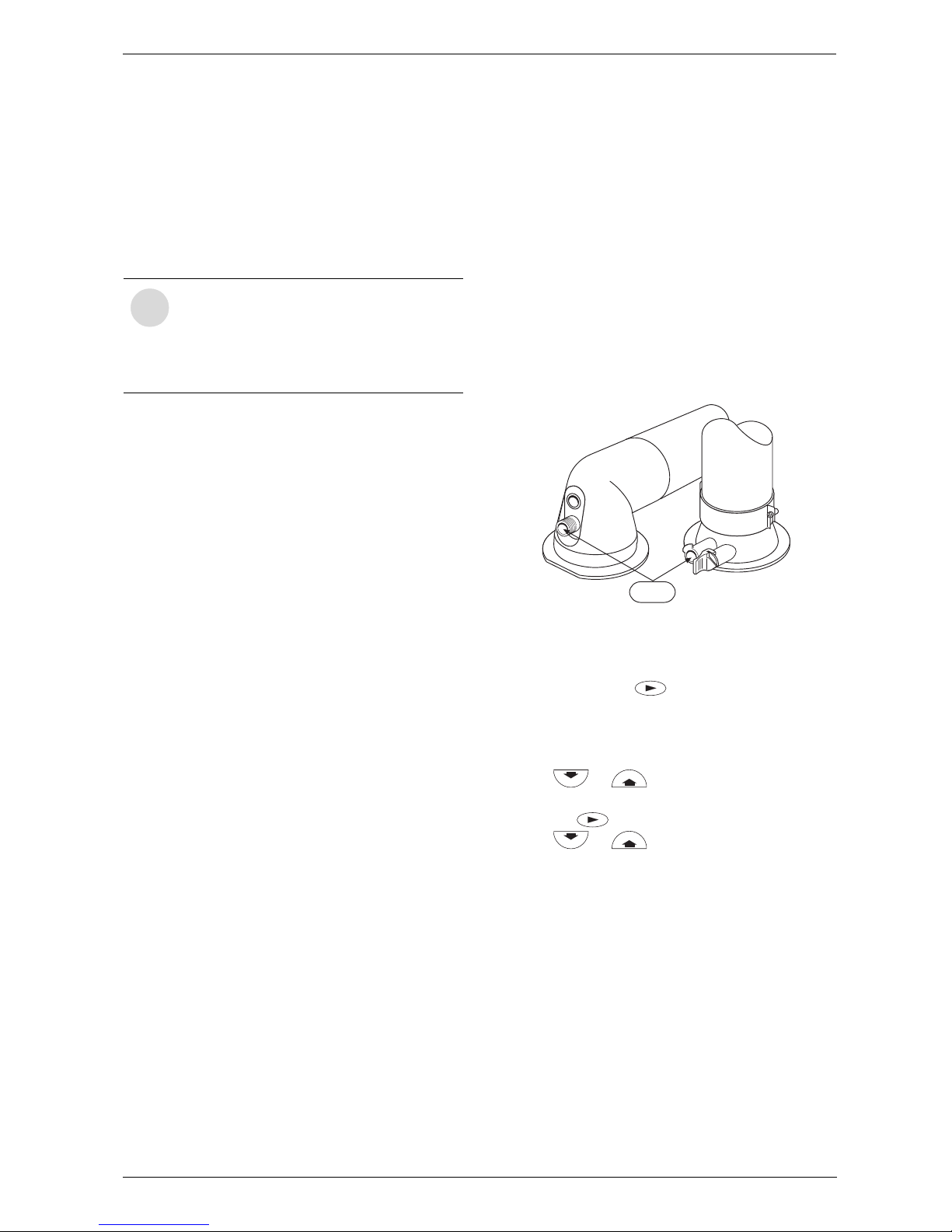
6 720 611 447 GB (03.11)
Converting the appliance to different gas types
33
8 Converting the appliance to different gas types
The setting is factory sealed at maximum. Adjustment to
the rated heat input and min. heat input is not necessary.
Checking the gas supply pressure
B Check the gas supply pressure at the gas supply
pressure testing point.
Natural gas
•Appliances for natural gas type G20 are factory set
to Wobbe-Index 15 kWh/m
3
and 20 mbar supply
pressure and sealed.
8.1 Setting the gas/air ratio
The gas/air ratio may only be adjusted on the
basis of a CO
2
measurement at max. heat output
and min. heat output using an electronic tester.
B Switch off the appliance at the master switch (O).
B Remove the outer case (see page 14, refer to
fig. 13).
B Switch on the appliance at the master switch (I).
B Unscrew sealing plug from flue gas testing
point (234). Refer to fig. 42.
B Insert testing probe about 135 mm into the flue gas
testing point and seal testing point.
Fig. 42
B On the text display unit, select in the main menu Set-
tings, Service, Display service parameters.
B Press and hold the button (for about 5 sec-
onds) until the display shows Adjust service
parameters and the first service function to be set,
2.0 Operating mode. If a fault has occurred, the
display will show 0.0 and the last fault.
B Press or until the display shows 2.0
Operating mode normal.
B Press the button.
B Press or to select Max.
B Measure the CO
2
level.
B Prise off the seal on the gas flow restrictor.
B Adjust the gas flow restrictor (63) to obtain the CO
2
level given in Table 15. Refer to fig. 43
i
Natural gas appliances must not be operated if the gas supply pressure is below
18 mbar or above 24 mbar.
LPG appliances must not be operated if
the supply pressure is below or above
37 mbar.
6 720 610 599 - 01.TD
234
Page 34
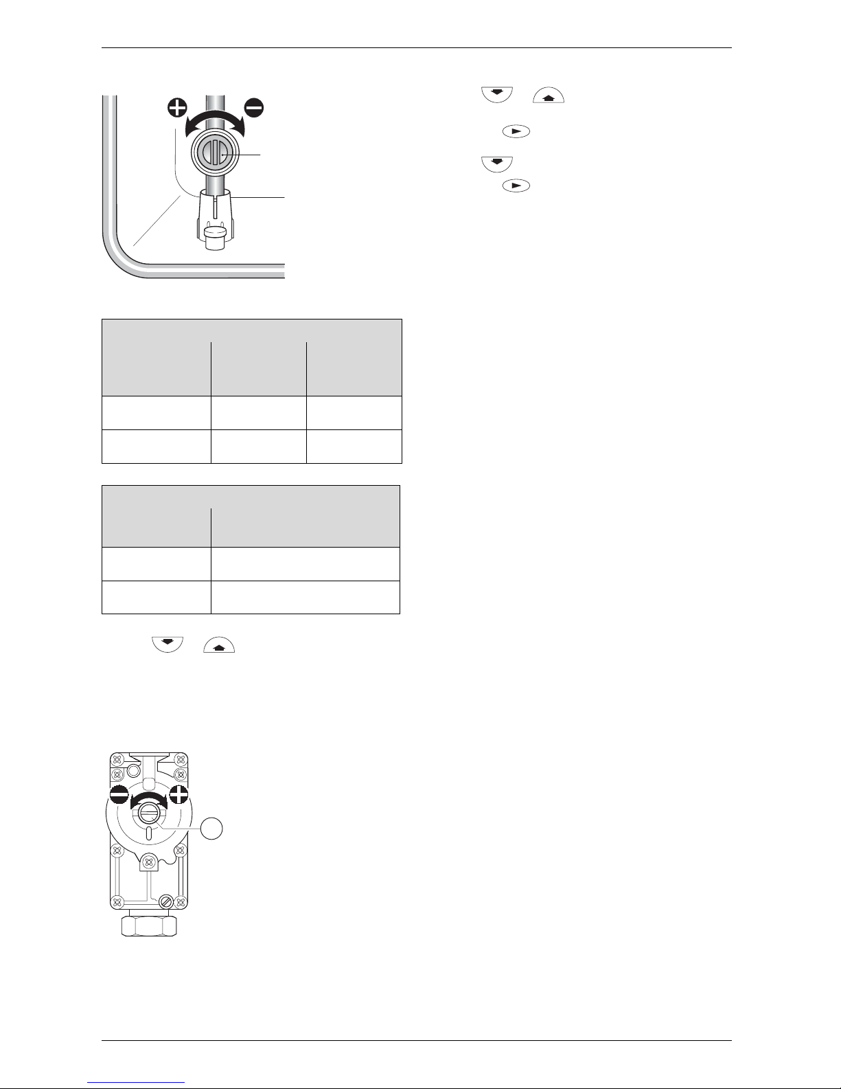
6 720 611 447 GB (03.11)
34
Converting the appliance to different gas types
Fig. 43
B Press or to select Min.
B Measure the CO
2
level.
B Remove the seal from the gas valve adjusting
screw (64) and adjust the CO
2
level to the figure
given in Table 15 for min. rated heat output. Refer to
fig. 44.
Fig. 44
B Recheck the levels at min. and max. rated heat output
and re-adjust if necessary.
B Press or until the display shows
normal.
B Press the button. The text display shows
Store settings.
B Press to select yes.
B Press the button.
B Remove testing probe from the flue gas testing
point (234) and refit sealing plug.
B Re-seal gas valve adjusting screw and gas flow
restrictor.
B Replace the outer case by locating it on the top lugs
and pushing backwards until the bottom clips are
fully engaged. Check that the case is properly
aligned with facia. Refer to fig. 13.
B Secure by replacing the screw at the bottom left.
Refer to fig. 13.
RD532i
Gas Type
CO2 reading
at max. rated
heat output
CO2 reading
at min. rated
heat output
Natural gas type
G20
9.2 % 8.8 %
LPG G31
(propane)
10.8 % 10.5 %
Table 15
RD537i/542i
Gas Type
CO2 reading at max. and min.
rated heat output
Natural gas type
G20
9.2 %
LPG G31
(propane)
10. 8 %
Table 16
63
6 720 610 332-64.1R
6
4
3928-74.1R
Page 35
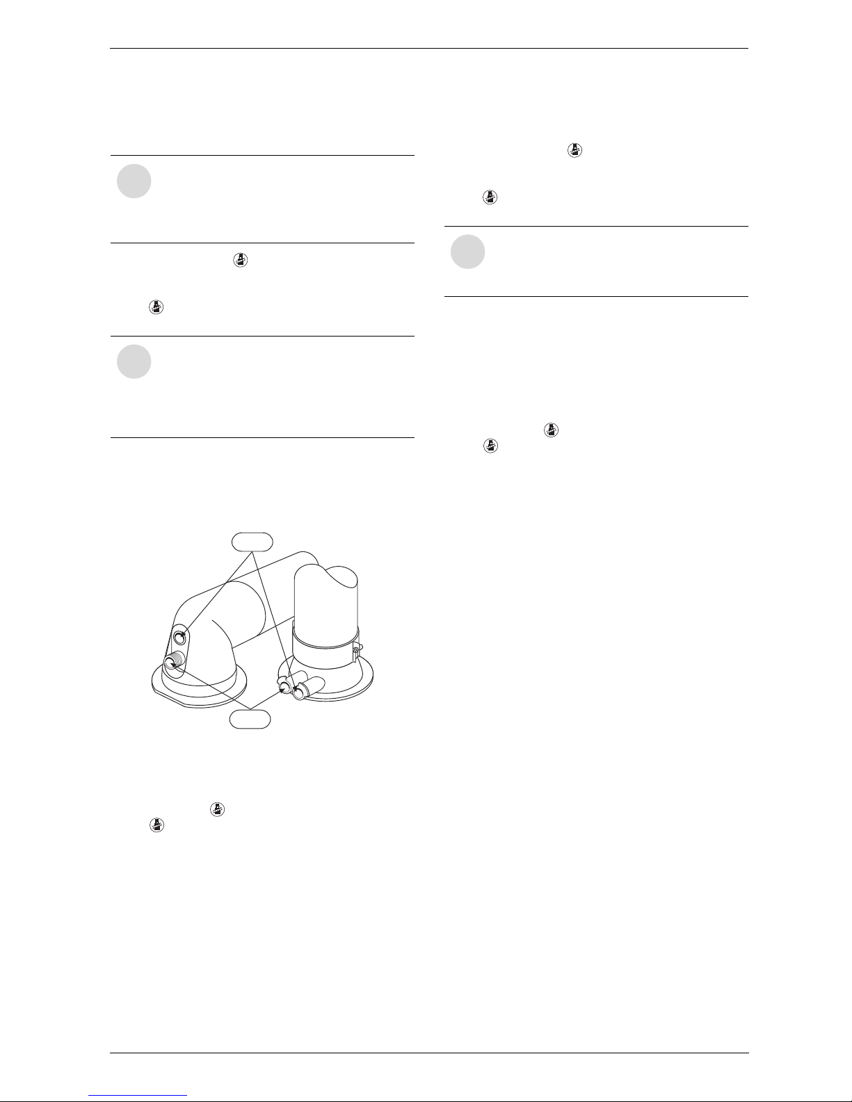
6 720 611 447 GB (03.11)
Converting the appliance to different gas types
35
8.2 Testing combustion air/flue gas at set heat output
8.2.1 Testing the O2 or CO2 level in the
combustion air
B Press and hold the button until the display
shows ––.
“Chimney sweep” mode is now active.
The button will light up and the display shows the
CH flow temperature.
B Remove sealing plug from combustion air testing
point (234.1, fig. 45).
B Insert testing probe about 80 mm into the testing
point and seal testing point.
Fig. 45
B Measure O
2
and CO2 levels.
B Refit sealing plug.
B Press and hold button until the display shows ––.
The button will stop flashing and the display
shows the CH flow temperature.
8.2.2 Testing CO and CO
2
B Press and hold the button until the display
shows ––.
“Chimney sweep” mode is now active.
The button will light up and the display shows the
CH flow temperature.
B Remove sealing plug from flue gas testing point
(234, fig. 45).
B Insert testing probe about 135 mm into the testing
point and seal testing point.
B CO- and CO
2
levels.
B Refit sealing plug.
B Press and hold button until the display shows ––.
The button will stop flashing and the display
shows the CH flow temperature.
i
By testing the O2 or CO2 level in the combustion air the gas tightness of a type C
13
,
C
33
flue system can be checked. The
O
2
level must not be less than 20,6 %.
The CO
2
level must not exceed 0,2 %.
i
In “chimney sweep” mode, the appliance
switches to max. rated heat output or the
set heating output. You then have 15 minutes in which to measure the levels. After
that, the appliance switches back from
“chimney sweep” mode to normal mode.
6 720 610 599 - 01.TD
234.1
234
i
You have 15 minutes in which to measure
the levels. After that, the appliance switches back from “chimney sweep” mode to
normal mode.
Page 36
6 720 611 447 GB (03.11)
36
Maintenance
9 Maintenance
B The User should be recommended to have the appli-
ance serviced regularly by a competent person.
B Use only genuine spare parts
B Refer to the Spare Parts List when ordering spare
parts.
B Always renew seals and O-rings removed during
servicing or repair work.
B Use only the following types of grease:
– Water valve: WRAS approved silicon based
grease
– Unions: approved sealant.
B To drain the appliance shut the system valves and
open the pressure relief valve.
B Upon completion of any electrical work check for
earth continuity, correct polarisation and resistance
to earth.
Replace the text display module or the Heatronic
PCB
If the text display module is replaced, the service function settings are retained.
B The remaining settings have to be re-entered.
If the Heatronic PCB is replaced:
B Re-enter the service function settings as recorded in
the commissioning record.
B Always disconnect the appliance from
the electrical power supply (fuse, circuit
breaker) before carrying out any work on
the electrical systems or components.
B Always turn off the gas cock before car-
rying out any work on components
which carry gas.
i
There is a Service booklet for the Engineer, order no. 7-181-465-349, available
to competent persons.
i
All safety and control systems are monitored by the Bosch Heatronic. In the event
of a component fault, the text display
shows a fault code.
Page 37

6 720 611 447 GB (03.11)
Maintenance
37
9.1 Pre-Service Check List
Date
1 Call up the last fault stored by the text
display, (see page 30).
2 Check ionisation current, Service
Function 3.3, (see page 38).
3 Perform visual check of air/flue duct.
Visual check of diaphragm for soiling
and splits (see page 40).
4 Check gas supply pressure
(see page 33).
mbar
5 Test combustion air/flue gas
(see page 35).
6 Check CO
2
setting for min./
max. (gas/air ratio)
(see page 33).
min. %
max. %
7 Check gas and water systems for
leaks (see page 15).
8 Check hot water outlet temperature
(see page 38).
9 Check heat exchanger
(see page 38).
mbar
10 Check burner (see page 39).
11 Clean condensation trap
(see page 40).
12 Check charge pressure of
expansion vessel matches
static head of heating system.
mbar
13 Check central heating system
pressure.
mbar
14 Check electrical wiring for damage.
15 Check heating programmer settings in
the text display.
16 Check appliances that are part of
the heating system.
Table 17
Page 38
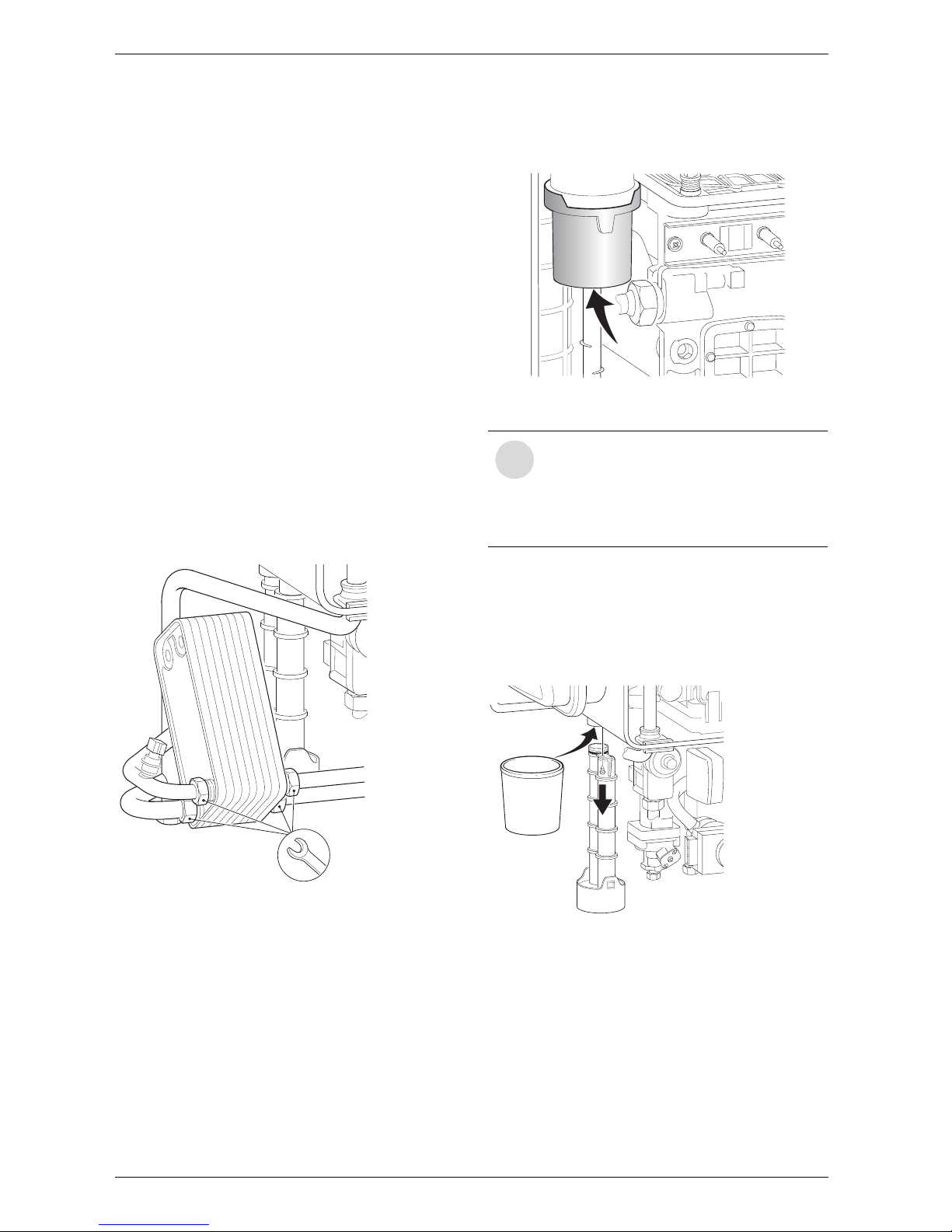
6 720 611 447 GB (03.11)
38
Maintenance
9.2 Description of servicing operations
The combustion performance must be checked before
and after any servicing work on the combustion and
burner components. Refer to section 8.2.
Checking the ionisation current,
Service Function 3.3
B Select Service Function 3.3. (See page 31 “Display-
ing Service Functions”)
If the display shows ‘Meduim’ or ‘High’ while the boiler
is firing, the ionisation current is OK. If the display
shows ‘No’ or ‘Low’ while the boiler is firing, the electrode assembly (32.1, page 6) must be cleaned or
replaced.
Domestic hot water
If, after checking the dynamic pressure, the flow rate is
too slow:
B remove the domestic hot water heat exchanger and
replace,
B Before removing the heat exchanger shut the inlet
valve and drain the hot water circuit.
B Use new seals when replacing the heat exchanger.
Fig. 46
Primary Heat exchanger
There is a special accessory kit (no. 840) for cleaning
the heat exchanger, order no. 7 719 001 996.
B Check control pressure on the air - gas mixer unit at
max. rated heat output using an electronic manometer.
Fig. 47
B Remove cleaning access cover (415, page 6) and
the metal plate below it, if present. Refer to fig. 2.
B Unscrew condensation trap and place suitable con-
tainer underneath. Refer to fig. 48.
B Remove the fan and the burner as described in the
text headed “Burner” (see page 39).
Fig. 48
7 181 465 330-06.1R
i
The heat exchanger should only be
cleaned if the control pressure is
5.2 mbar (RD532i)
5.3 mbar (RD537i)
6.2 mbar (RD542i)
(depression) or less.
6 720 610 332-69.1R
6 720 610 332-72.1R
Page 39
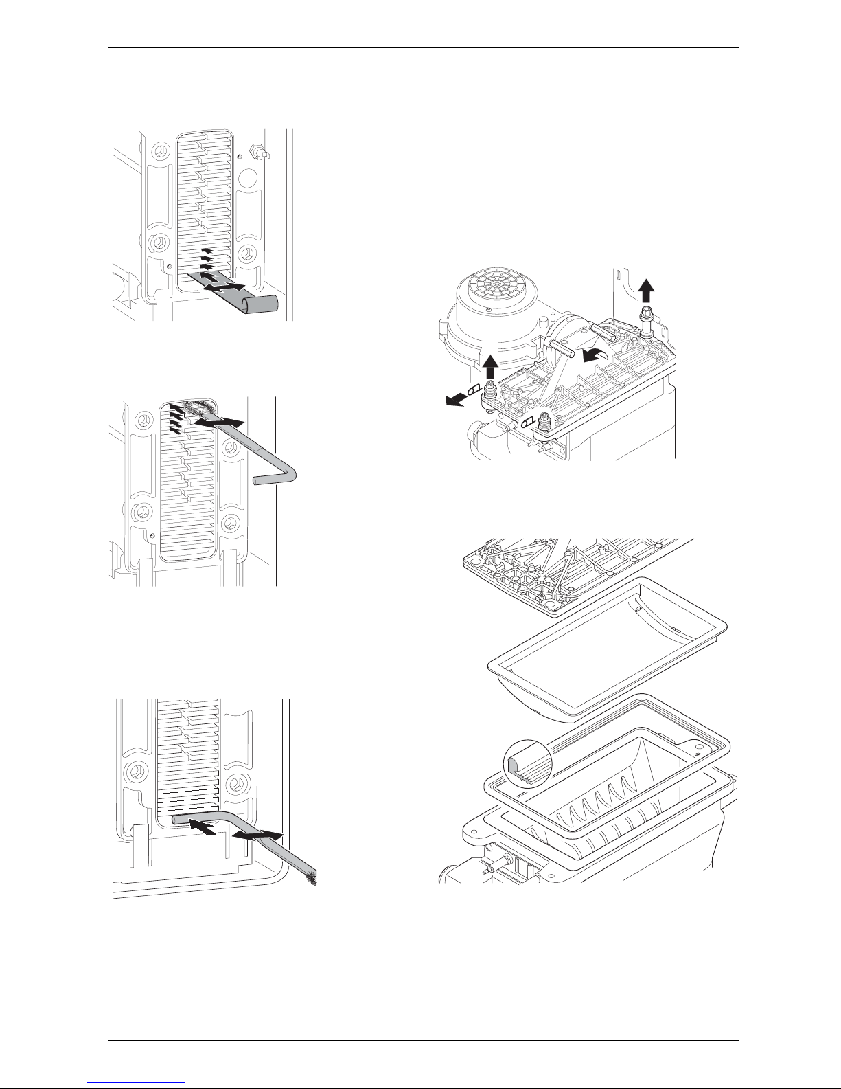
6 720 611 447 GB (03.11)
Maintenance
39
B Loosen any deposits in the heat exchanger from top
to bottom using the cleaning blade. Refer to fig. 49.
Fig. 49
B Clean the heat exchanger from top to bottom using
the brush. Refer to fig. 50.
Fig. 50
B Flush the heat exchanger from the top. Refer to
fig. 51.
B Clean out the condensate collector and trap connec-
tion (with other end of brush).
Fig. 51
B Refit the clean-out cover using a new seal and
tighten screws to torque of approx. 5 Nm.
Burner
B Check that the gas cock is turned off and the master
switch is in the OFF position
B Remove the clips (1) and unscrew the two bolts (2).
Refer to fig. 52.
B Unscrew and remove the two hexagon screws secur-
ing the fan (3).
B Slacken fully the rear securing bolt (4).
B Remove the burner coverplate.
Fig. 52
B Remove the burner skin and clean components. Do
not use a wire brush. Refer to fig. 53.
Fig. 53
B Re-assemble burner in reverse order, inspect seal for
damage and replace if necessary.
B Adjust gas/air ratio. Refer to section 8.2.
6 720 610 332-73.1R
6 720 610 332-74.1R
6 720 610 332-75.2
R
1.
2.
4.
7 181 465 330-04.1R
3.
7 181 465 330-09.2R
Page 40
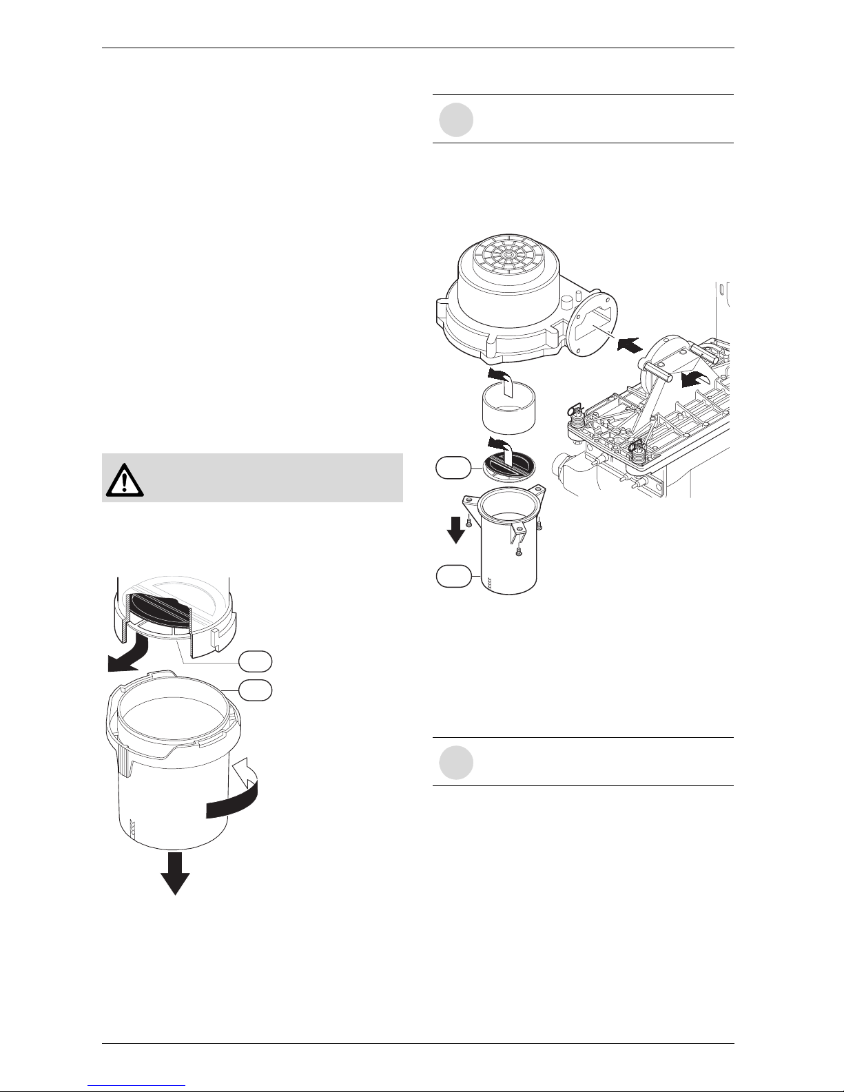
6 720 611 447 GB (03.11)
40
Maintenance
Condensation trap
In order to prevent spillage of condensate the condensation trap should be completely removed, (see
page 38, fig. 48).
B Unscrew condensation trap and check connection to
heat exchanger is clear.
B Remove condensation trap cover and clean.
B Fill condensation trap with approx. 1/4 l of water and
refit.
Electrode assembly
B Switch off the master switch.
B Pull off the leads from the electrodes. Refer to fig. 2.
B Unscrew the two fixing screws and carefully remove
the electrode assembly. Refer to fig. 47.
B Clean the electrodes with a non-metallic brush. (The
spark gap should be 4,5 mm ± 0,5 mm.)
B Replace and re-connect the assembly taking care not
to mislay the inspection window.
Diaphragm in mixer unit for RD532i
B Open mixer unit (29).
B Carefully withdraw diaphragm (443) from fan intake
tube and check for soiling and splits.
Fig. 54
B Carefully refit diaphragm (443) the correct way round
into the fan intake tube.
B Seal the mixer unit (29).
Diaphragm in mixer unit for RD537i/542i
B Remove fan and mixer unit assembly.
Fig. 55
B Unscrew mixer unit (29).
B Remove sleeve.
B Carefully remove diaphragm (443) and check for soil-
ing and cracks.
B Refit diaphragm (443) taking care to ensure it is the
correct way round.
B Refit mixer unit (29) and fan assembly.
B Take care not to damage diaphragm
(443) when removing and refitting it.
1.
2.
3.
44
3
29
6 720 610 790-07.2R
i
The flaps of the diaphragm (443) must
open upwards.
i
The flaps of the diaphragm (443) must
open upwards.
1.
2.
3.
4.
5.
443
6 720 610 910-63.1R
29
Page 41
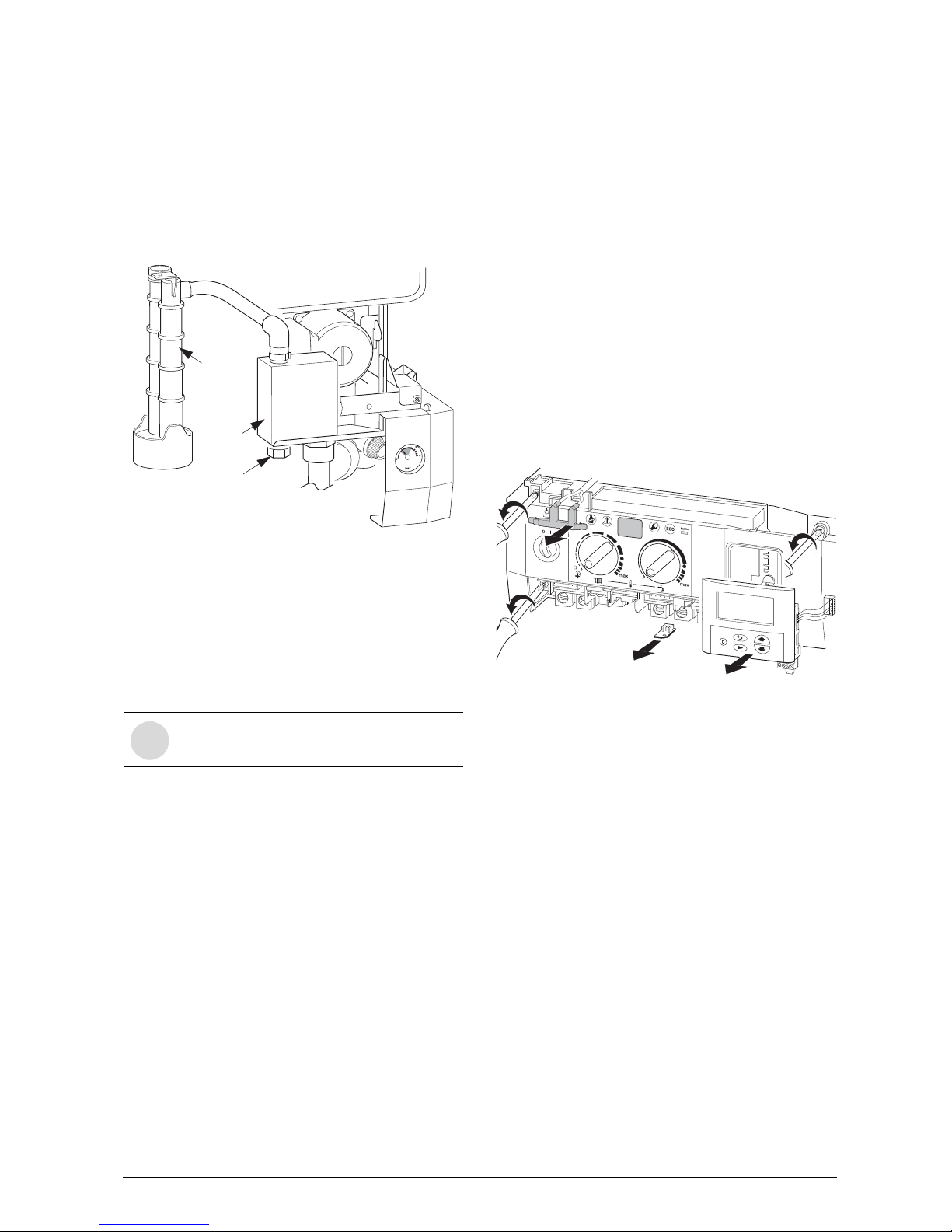
6 720 611 447 GB (03.11)
Maintenance
41
Siphon
B Unscrew the clip and disconnect the pipe to the
siphon.
B Remove the drain plug to drain the siphon.
B Unscrew the securing nut from beneath the side
facia and remove the siphon. Refer to figure below.
B Refit and prime the siphon.
Fig. 56
Expansion vessel
The expansion vessel should be checked once a year.
B Depressurise appliance.
B If necessary, adjust expansion vessel charge pres-
sure to static head of the heating system.
Heating system pressure
B The pointer on the pressure gauge should be 1 bar.
B If the pointer is below 1 bar (when the system is
cold), water should be added until the pointer is
1 bar again.
B Max. pressure of 2.5 bar when the heating system
water is at maximum temperature must not be
exceeded. If this pressure is exceeded then an extra
expansion vessel must be fitted in the system return
as close to the appliance as possible.
B If the system does not retain the pressure, the expan-
sion vessel and the heating system should be
checked for leaks.
9.3 Replacement of Parts
Before changing any components check that the gas is
turned off and that the appliance is electrically isolated.
When necessary close the system valves and drain the
appliance.
Refitting is a reverse of the procedure for removal using
new seals or o-rings as appropriate.
9.3.1 PCB control board and transformer
B Switch off the appliance.
B Disconnect appliance from the power supply.
B Unplug all connectors from the control box (inc.
keyed plug). Access is gained by removing the covers. Refer to fig. 25, 26.
B Remove screw holding power connector earth lead
and remove earth lead.
B Remove two top fixing screws from the control box.
Refer to fig. 57.
Fig. 57
B Lower the control box.
B Unscrew earth lead.
B Unscrew four fixing screws from cover plate. Refer to
fig. 58.
B Prise off cover plate.
B Pull off transformer.
B Remove pcb holder.
i
Fill the system using the WRAS approved
filling loop.
Condensate
Drain
Siphon
Drain Plug
181 465 330-09.1R
1
2
3
4
5
E
1
3
2
4
1
3
2
4
1
3
2
4
Page 42
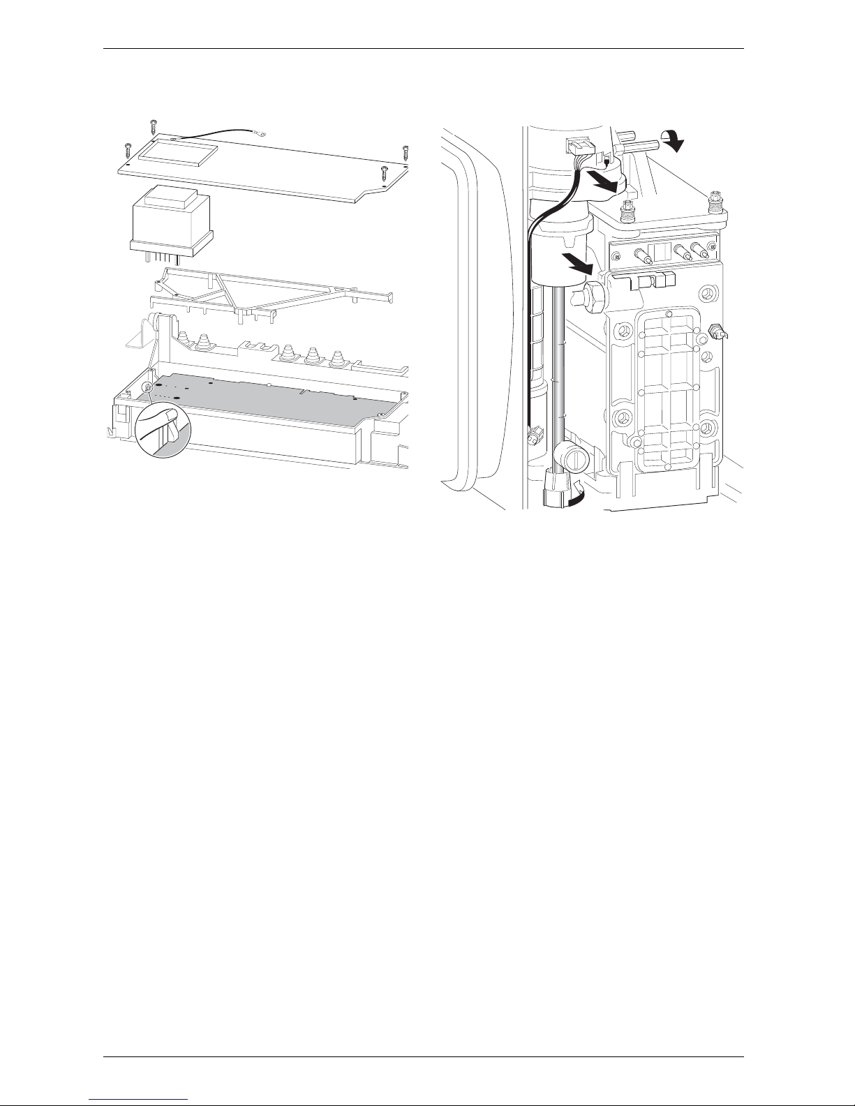
6 720 611 447 GB (03.11)
42
Maintenance
B Remove the pcb control board.
Fig. 58
Fuses
B Remove the connections covers. Refer to fig. 25,
26.
The fuses are located adjacent to the mains connector
block and connector ST18. Refer to fig. 4.
Fuse, item 312, is only replaceable by removing the
pcb.
Spare fuses are fixed to the connections cover.
A fuse pack is available: Part number 8 744 503 010 0.
9.3.2 Fan Assembly
Fig. 59
B Switch off the appliance.
B Undo lower pipe union on gas pipe (1.). Refer to
fig. 59.
B Remove fan lead and earth connector (2.). The earth
connector has a positive clip fixing.
B Remove fixing screws attaching fan to the burner
cover (3.).
B Remove fan together with gas pipe and mixer unit.
B Separate the fan from the pipe and mixer unit by
twisting the mixer unit to release it (4.).
9.3.3 Pump
B Switch off the appliance.
B Disconnect the appliance from the power supply.
B Remove two switch box fixing screws (1.). Refer to
fig. 60.
B Lower switchbacks (2.).
B Remove screw from underside of right-hand plastic
cover plate (3.).
B Pull cover plate forwards to remove (4.).
B Unscrew and remove the siphon by releasing the
jubilee clip. Refer to fig. 56.
B Unscrew the pump union nuts (5.). Refer to fig. 60.
B Carefully remove the pump and disconnect the leads.
7 181 465 330-10.1
R
1.
2.
3.
4.
7 181 465 330-05.1R
Page 43
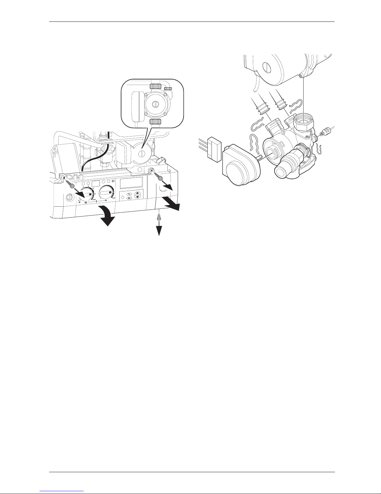
6 720 611 447 GB (03.11)
Maintenance
43
Alternatively
B After removing the siphon release the four Allen
screws and remove and replace the pump head.
Fig. 60
9.3.4 3-way diverter valve
B Switch off the appliance.
B Disconnect appliance from the power supply.
B Turn off service cocks.
B Unplug connector from 3-way valve motor. Refer to
fig. 61.
B Pull out retaining clip.
B Remove motor.
B Disconnect the relief valve drain.
B Disconnect the pressure gauge by withdrawing the
clip and pulling out the capillary head.
B Undo pipe unions by withdrawing the clips.
B Remove 3-way valve.
Fig. 61
After refitting:
B Fill system, bleed and re-pressurise
(see Installation Instructions).
9.3.5 3-way diverter valve motor
B Switch off the appliance.
B Turn off the service cocks.
B Unplug connector from 3-way valve motor. Refer to
fig. 61.
B Pull out retaining clip.
B Remove motor.
9.3.6 Sensors
B Check that the appliance is electrically isolated.
Central Heating Flow Temperature Sensor –
Item 36, fig. 2, 57
B Pull-off the connector.
B Release the sensor clip and withdraw the sensor.
B Apply heat transfer paste to the replacement sensor.
Safety Temperature Limiter – Item 6, fig. 2, 57
B Pull-off the connectors.
B Unscrew the sensor.
Flue Temperature Limiter – Item 9, fig. 2, 57
B Pull-off the connectors.
B Unscrew the sensor.
1.
1.
2.
3.
4.
5.
7 181 465 330-03.1R
7 181 465 330-12.1
R
Page 44
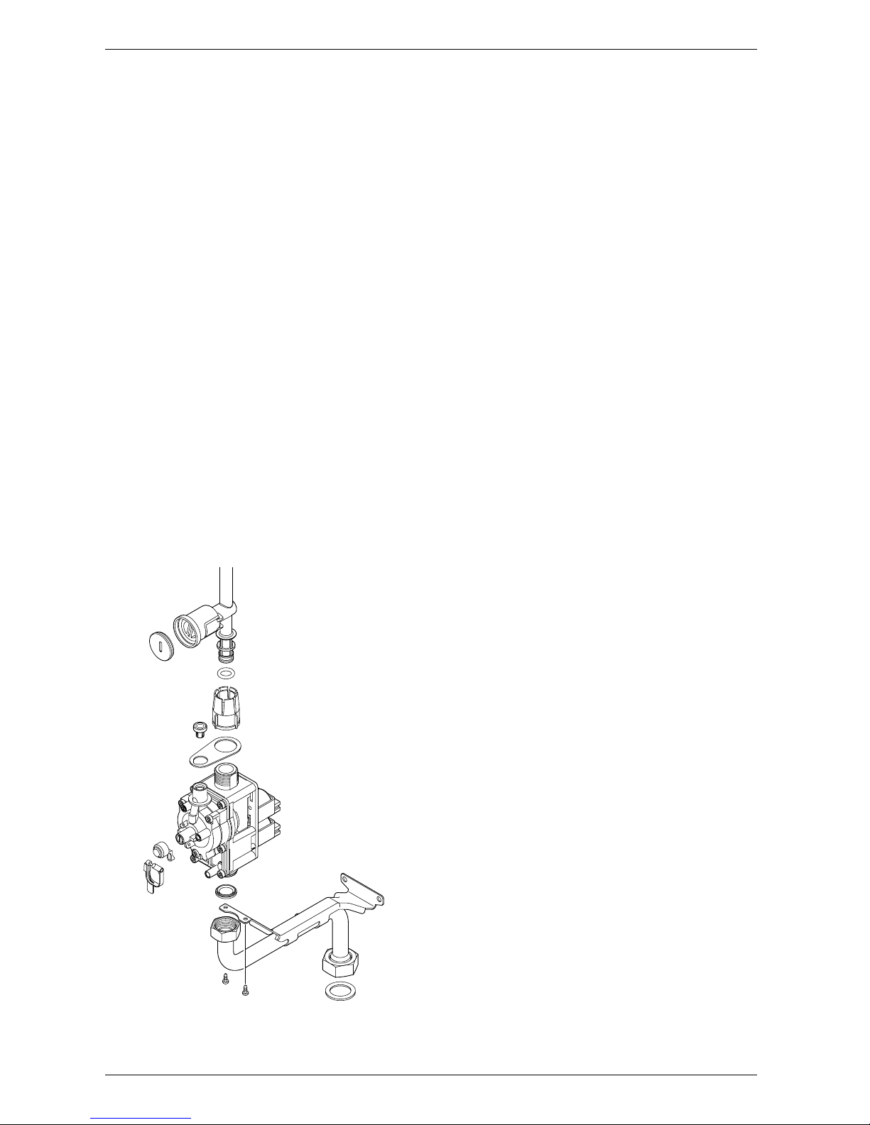
6 720 611 447 GB (03.11)
44
Maintenance
Domestic Hot Water Temperature Sensor –
Item 6.1, fig. 2
B Check that the inlet water valve is closed and the
domestic hot water circuit is drained.
B Release and pull-off the connector.
B Unscrew the sensor.
9.3.7 Gas Valve
B Check that the gas cock is turned off.
B Lower the control panel. Refer to fig. 60.
B Pull off the solenoid connections at the rear of the
valve.
B Undo the union, within the inner casing, securing the
valve to the gas/air tube. Refer to fig. 59.
B Remove the white plastic cap from the gas valve.
B Release the gas inlet union at the manifold assembly.
B Unscrew the two screws securing the gas valve
assembly bracket to the back panel and withdraw the
assembly.
B Transfer the bracket and inlet pipe assembly to the
new gas valve.
B Check for gas soundness when the new gas valve
has been fitted.
B Recheck the combustion performance as described
in section 8.1.
Fig. 62
9.3.8 Domestic Hot Water Heat Exchanger
B Refer to section 9.2.
B Use new seals when fitting the new heat exchanger.
9.3.9 Electrode assembly
B Refer to section 9.2.
B Use a new seal if the existing seal is damaged.
9.3.10 Pressure gauge
B Drain the appliance.
B Lower the facia. Refer to fig. 60.
B Twist the pressure gauge head anti-clockwise to
release it from the casing. Refer to fig. 2.
B Disconnect the capillary head from the rear of the
diverter valve by withdrawing the clip and pulling out
the head. Refer to fig. 61.
9.3.11 Expansion vessel
B Drain the appliance.
B Undo the union connection at the base of the vessel.
Refer to fig. 2.
B Unscrew the top and bottom fixing screws and
remove the vessel.
B Set the pressure of the new vessel to that required by
the system.
9.3.12 Pressure Relief Valve
B Drain the appliance.
B Disconnect the drain pipe from the valve. Refer to
fig. 30.
B Pull-out the clip securing the valve.
B Pull-out the valve.
B Ensure that the replacement valve is fully entered
before fitting the clip.
9.3.13 Burner
B Refer to section 9.2.
6 720 610 602 - 04.1O
Page 45
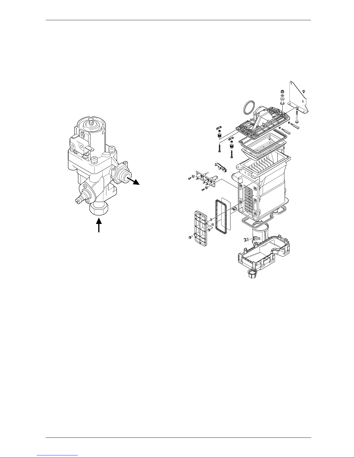
6 720 611 447 GB (03.11)
Maintenance
45
9.3.14 Flow switch
B Shut the mains water inlet valve and drain the domes-
tic hot water circuit.
B Pull-off the connectors from the micro-switch.
B Unscrew the inlet and union connection and remove
the assembly.
B Reset the domestic hot water flow rate on the new
assembly.
Fig. 63
9.3.15 Primary Heat Exchanger
B Drain the appliance.
B Check that the gas supply is turned off.
B Check that the appliance is electrically isolated.
B Remove the fan assembly complete with the gas/air
tube and mixer assembly. Refer to section 9.3.2.
B Remove the burner. Refer to section 9.2.
B Disconnect the sensors. Refer to section 9.3.6.
B Undo the central heating flow union.
B Undo the top connection of the pump. Refer to
fig. 57.
B Undo the grey plastic cap, next to the top pump con-
nection at the base of the heat exchanger.
B Unscrew and remove the condensate trap. Refer to
section 9.2.
B Unscrew and remove the two screws securing the
heat exchanger top bracket to the rear panel.
B Lift up the flue duct, item 271, refer to fig. 2.
B Pull forward from the top and lift the heat exchanger
from the casing.
B Transfer components, as necessary, to the new heat
exchanger.
B Ensure that all the seals are in place and all of the
connections are tight before re-commissioning the
appliance.
Fig. 64
6 720 610 602 - 05.10
INLET
OUTLET
6 720 610 602 - 06.10
Page 46
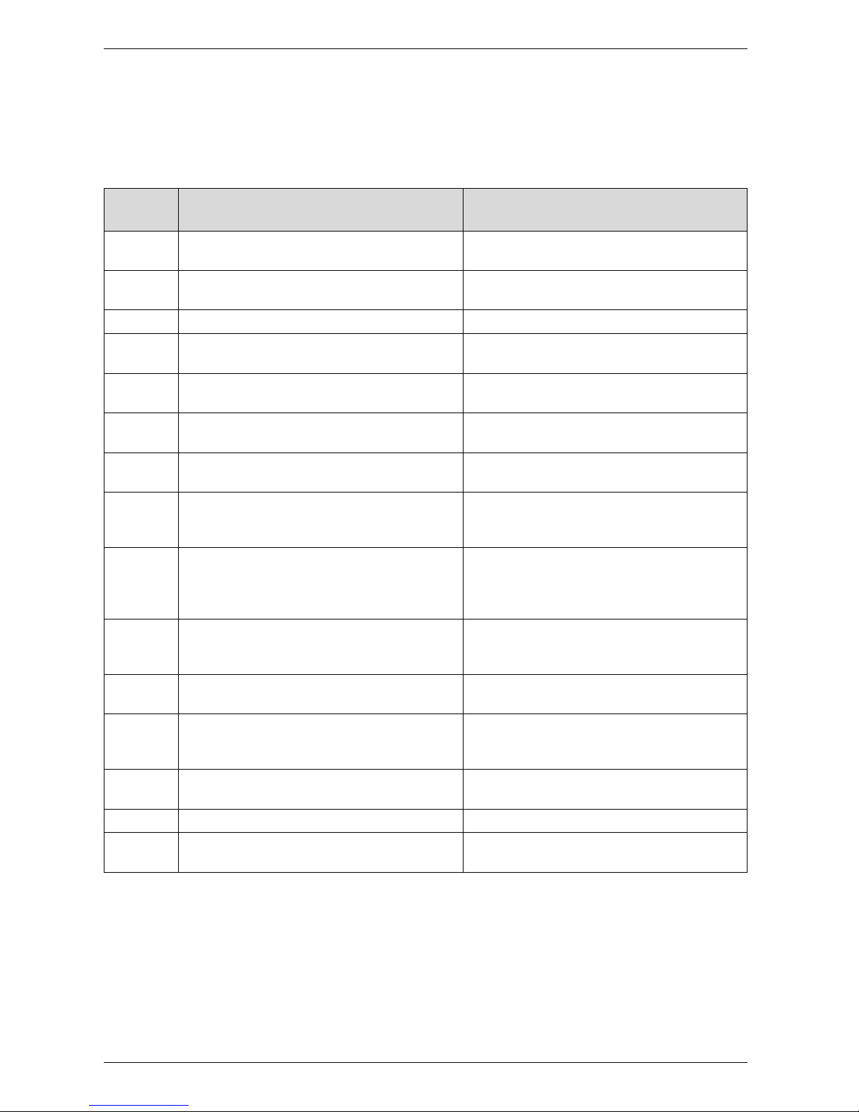
6 720 611 447 GB (03.11)
46
Appendix
10 Appendix
10.1 Fault Codes
More detailed fault finding procedures are described in the Service Booklet for the Engineer number 7 181 465 347.
Display
code
Description Remedy
A1 pump has run dry Check system pressure, add water and bleed
system as necessary
A7 Hot water NTC sensor defective. Check hot water NTC sensor and connecting
lead for circuit breaks/short circuits.
A8 Break in communication Check connecting lead to TR2
b1 Code plug not detected. Insert code plug correctly, test and replace if
necessary.
C1 Fan speed too low. Check fan lead and connector, and fan; replace
as necessary.
d3 Jumper 8-9 not detected. Connector not connected, link missing, under-
floor heating limiter tripped.
E2 CH flow NTC sensor defective Check CH flow NTC sensor and connecting
lead.
E9 Safety temp. limiter in CH flow has tripped. Check system pressure, check safety temp. lim-
iters, check pump operation, check fuse on pcb,
bleed appliance.
EA Flame not detected. Is gas cock turned on? Check gas supply pres-
sure, power supply, igniter electrode and lead,
ionisation sensing electrode and lead, flue duct
and CO2 level.
F0 Internal error. Check electrical connector contacts, program-
mer interface module ignition leads are not
loose; replace pcb if necessary.
F7 Flame detected even though appliance
switched off.
Check electrode assembly, dry pcb. Flue clear?
FA Flame detected after gas shut off. Check gas valve and wiring to gas valve. Clean
condensation trap and check electrode assembly. Flue clear?
FC Text display not detected. Check connecting lead between Text display
and Heatronic, replace Text display if necessary
Fd Reset button pressed by mistake. Press reset button again
P1, P2,
P3, P1...
Please wait, initialisation in progress. 24 V fuse blown. Replace fuse.
Table 18
Page 47
6 720 611 447 GB (03.11)
Appendix
47
10.2 Short parts list
Key Description Qty GC Spare part number
1 Sensor - Flue gas temp. 1 8 722 963 858 0
2 Sensor - CH flow temp. 1 8 714 500 087 0
3 Sensor - DHW flow temp. 1 8 714 500 054 0
4 Control board pcb 1 8 748 300 495 0
5 Gas valve ZWBR 8-30 1 8 747 003 516 0
5.1 Gas valve ZWBR 11-37 1 8 747 003 515 0
6 Fan assembly 1 8 717 204 325 0
7 Fan washer 1 8 729 000 183 0
8 Expansion vessel 1 8 715 407 246 0
9 Relief valve 1 8 717 401 012 0
10 Electrode assembly 1 8 718 107 077 0
11 Electrode lead 1 8 714 401 999 0
12 Pump 1 8 717 204 350 0
13 Pressure gauge 1 8 717 208 079 0
14 Burner skin seal 1 8 711 004 168 0
15 Transformer - facia 1 8 747 201 358 0
16 Flow switch 1 8 717 002 110 0
17 3-way diverter valve 1 8 717 010 062 0
18 Heat exchanger washer 1 8 710 103 153 0
19 Washer set Condensation
Tr ap
1 8 710 10 3 15 4 0
20 Fuse set 1 8 744 503 010 0
21 Service set Water Valve 1 8 710 503 031 0
22 Domestic Hot Water Heat
Exchanger
1 8 715 406 659 0
23 Text Display 1 8 747 208 103 0
24 Primary heat exchanger 1 8 715 406 615 0
25 Diaphragm 1 8 715 505 801 0
Table 19
Page 48
6 720 611 447 GB (03.11)
48
Appendix
10.3 Heating/hot water output settings
RD532i N.G.
10.4 Heating/hot water output settings
RD532i L.P.G
10.5 Heating/hot water output settings
RD537i N.G.
10.6 Heating/hot water output settings
RD537i L.P.G
Natural gas G20
Display
code
Heat
output,
kW
Heat
input,
kW
Gas vol. flow rate
(l/min at
t
V/tR
= 80/60°C)
30 9.1 9.2 16.0
40 12.1 12.2 21.4
50 15.1 15.3 26.7
60 18.1 18.3 32.0
70 21.1 21.4 37.4
80 24.2 24.4 42.7
90 27.2 27.5 48.0
100 30.2 30.5 53.4
Table 20
Propane
Display
code
Heat output kW Heat input kW
40 12.1 12.2
50 15.1 15.3
60 18.1 18.3
70 21.1 21.4
80 24.2 24.4
90 27.2 27.5
100 30.2 30.5
Table 21
Natural gas G20
Display
code
Heat
output,
kW
Heat
input,
kW
Gas vol. flow rate
(l/min at t
V/tR
=
80/60°C)
30 11.1 11.3 19.7
40 14.9 15.0 26.3
50 18.6 18.8 32.8
60 22.3 22.5 39.4
70 26.0 26.3 45.9
80 29.7 30.0 52.5
90 33.4 33.8 59.1
100 37.1 37.5 65.6
Table 22
Propane
Display
code
Heat output, kW Heat input, kW
40 14.9 15.0
50 18.6 18.8
60 22.3 22.5
70 26.0 26.3
80 29.7 30.0
90 33.4 33.8
100 37.1 37.5
Table 23
Page 49
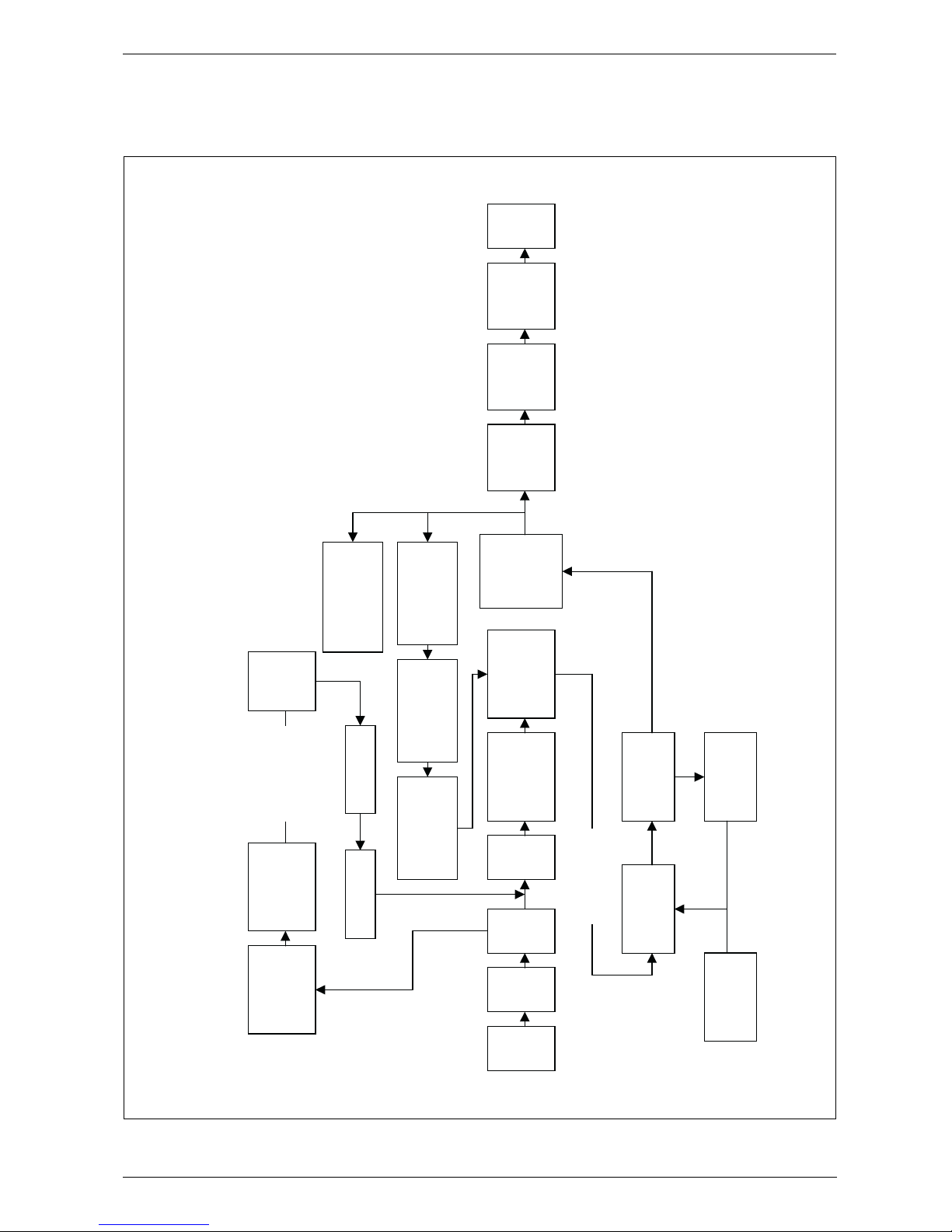
6 720 611 447 GB (03.11)
Appendix
49
10.7 Operational Flow diagrams
10.7.1 Domestic hot water function
Fig. 65
6 720 610 576 - 25.TD
Repeats 5 times
(N.G.) or 3 times
(L.P.G.) before
lock-out.
Ye s
No
Pump ON
Diverter valve
operates.
Fan to start
speed.Gas
valve opens.
Ignition sequence
Ignition
spark
5 secs
Pre-heat satisfied.
Burner lights.
Red light ON.
Burner shut-down if
primary temperature
exceeds 94°C remains
OFF until 78°C
Burner remains OFF
until flow
temperature is below
set value.
Gas valve shuts.
Pump remains ON.
Over temperature
shut down if water
temperature is 8°C
above set value.
** NOTE:
The appliance controls can be set to one of 2
modes of operation.
1. “Comfort“ mode -
Full pre-heat
2. “ECO“ mode -
a) Operates as an instantaneous combination boiler.
b) Demand Detection: a short demand (less than 5
seconds) switches the control to “Comfort“ mode
for 5 mins. Mini pre-heat. The Factory setting is
“Comfort“ mode.
Mains
switch
ON.
Green
light
ON.
Pre-heat
mode.**
Hot
water
demand.
Pump ON
Diverter valve
operates.
Fan to start
speed. Gas valve
opens.
Heat input
modulates to
maintain the
delivery
temperature.
Demand
ends.
Gas valve
closes. Red
light OFF.
Fan runs for
up to 3 mins.
Pump runs for
30secs.
Pre-heat
mode.**
Ignition sequence
Ignition
spark
5 secs
Burner lights.
Red light ON.
Fan runs to purge
gas from burner.
Page 50
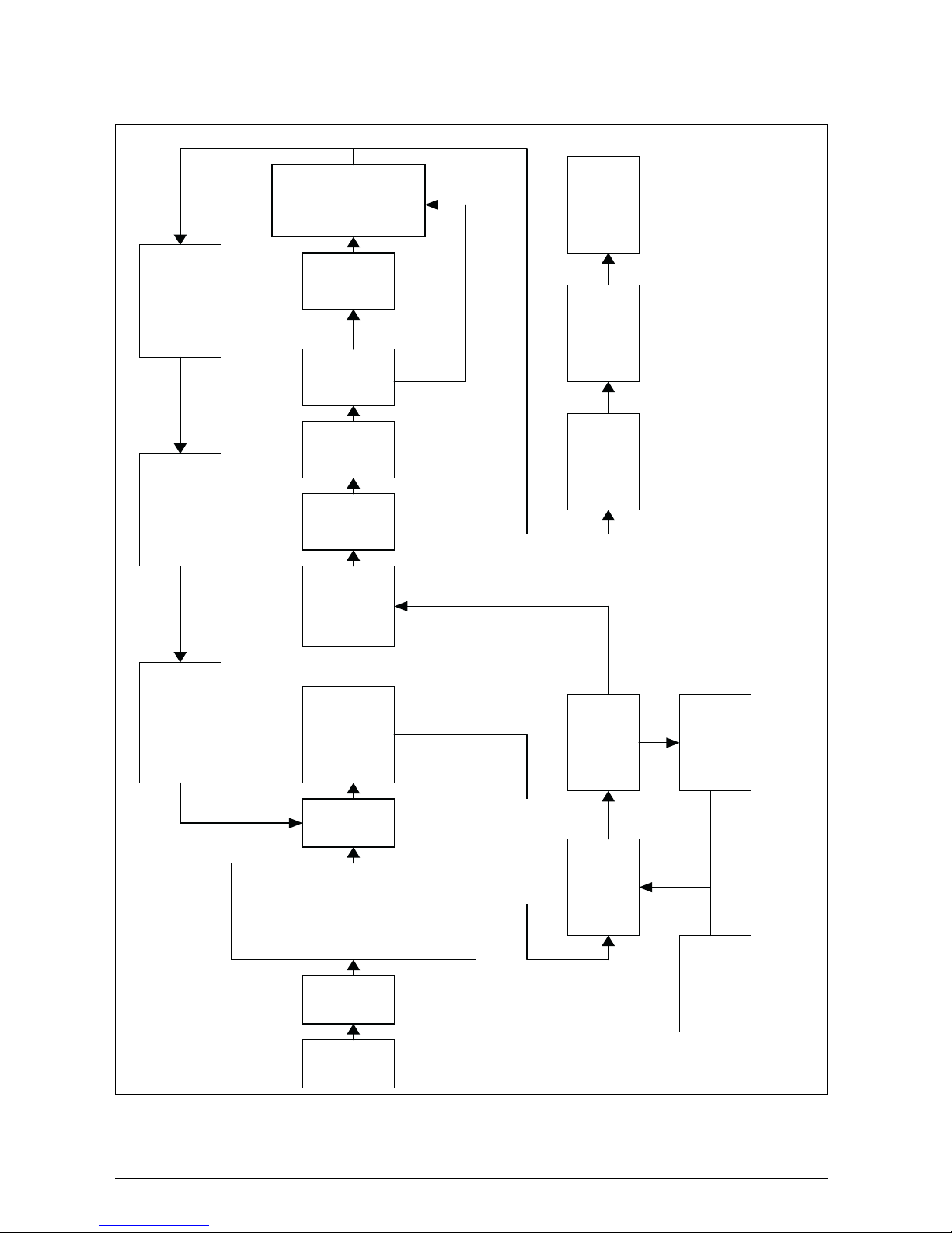
6 720 611 447 GB (03.11)
50
Appendix
10.7.2 Central heating function
Fig. 66
6 720 610 576 - 26.TD
Ye s
No
Ye s
No
Mains
switch
ON.
Green
light
ON.
Room
thermostat
and/or mains
programmer or
link ON AND
Electronic facia
programmer (if
fitted) ON AND
CH control
knob ON.
CH
demand.
Burner remains OFF
until flow temperature
is below set value.
Gas valve shuts.
Pump remains ON.
Over temperature
shut down if water
temperature is 5°C
above set value.
Pump ON Fan to
start speed. Gas
valve opens.
Burner
stabilises at
start speed for
5-10 secs
Fan speed
reduces
over 15
secs.
Fan min.
speed for
90 secs.
Boiler
unused
for long
period.*
*Minimum
heat
input for
15min.
Boiler
operates to
match
system load
and CH
control
setting.
Ignition sequence
Ignition spark for
5 seconds.
Burner lights. Red
light ON.
Repeats 5 times
(N.G.) or 3 times
(L.P.G.) before
lock-out.
Fan runs to
purge gas from
burner.
CH demand
satisfied.
Gas valve closes.
Red light OFF.
Pump and Fan
run for up to 3
mins.
* NOTE: The sequence ensures that the condensate siphon is not empty
after long
OFF
periods. (More than 24 hours without a demand).
Page 51

6 720 611 447 GB (03.11)
Appendix
51
Page 52

AppendixAppendix
EXCELLENCE COMES AS STANDARD
Manufactured exclusively for British Gas by The Bosch Group
Bosch Group, Worcester Heat Systems, Cotswold Way, Warndon, Worcester WR4 9SW.
Telephone: (01905) 754624 Fax: (01905) 754619
Page 53
Users Instructions and
Customer Care Guide
RD 532i/RD 537i/RD 542i combi Condensing boiler
RD 430i system Condensing boiler
6 720 610 598 - 00.2O
ZWBR 7-32 RD 532i GC-Number: 47 108 10
ZWBR 11-37 RD 537i GC-Number: 47 108 11
ZWBR 11-42 RD 542i GC-Number: 47 108 12
System boiler 7-30 RD 430i GC-Number: 41 108 06
6 720 610 604 GB (03.06) OSW
Page 54

Contents
Contents
Excellence comes as standard 4
Safety precautions 5
1 General notes 7
2 Controls 11
3 Operating the Appliance 12
3.1 Preparation 12
3.2 Switching the Appliance On/Off 14
3.3 Switching on the Central Heating 15
3.4 Controlling Central Heating 15
3.5 Combination Boilers: Setting Hot Water Temperature 16
3.6 System boiler with Storage Tank 17
3.7 Summer Mode, Hot Water Only (Combi Appliances) 18
3.8 Frost protection (Combi Appliances) 19
3.9 Fault Condition 19
4 Text Display 20
4.1 General Description 20
4.2 Programming 20
4.2.1 Deleting a setting 23
4.2.2 Resetting all parameters to their original settings 23
4.3 Menu structure 24
4.4 Setting the time/day 25
4.4.1 Setting the time and day 25
4.4.2 Holidays 25
4.5 Heating 27
2
6 720 610 604 GB (03.06)
Page 55

Contents
4.5.1 Heating program 27
4.5.2 Setting the Economy temperature (if TR2 is connected) 28
4.5.3 Manual operating mode (if TR2 is not connected) 29
4.6 Hot water 30
4.6.1 Hot water program 31
4.6.2 Hot water immediately (System models) 31
4.7 i Info 32
4.8 Settings 33
4.8.1 Heating (if TR 2 is connected) 33
4.8.2 Hot Water (Storage Tank, System boiler models only) 33
4.8.3 Service 33
4.9 Individual timer programmes 36
5Fault finding 37
6 Tips on saving energy 38
7 General Information 39
8 Maintaining your appliance 40
9Service 40
10 Fault or breakdown 41
11 Your guarantee 42
12 Guarantee registration 43
13 Operating Instructions Quick Reference 44
6 720 610 604 GB (03.06)
3
Page 56

Excellence comes as standard
Excellence comes as standard
Thank you for purchasing an RD 532i/RD 537i/RD 542i /RD 430i
condensing appliance.
The RD 532i/RD 537i/RD 542i /RD 430i Series has been developed by the Bosch Group and the strictest quality control standards are demanded throughout every stage of production.
Indeed, the Bosch Group have led the field in innovative appliance
design and performance for many years.
The result is that your new RD 532i/RD 537i/RD 542i /RD 430i
appliance offers you the very best of everything – quality, efficiency, economical running costs, proven reliability and value for
money.
What’s more, you also have the assurance of our no nonsense
2 year parts and labour guarantee.
And it’s backed up by British Gas - Offering a complete maintenance scheme to keep your boiler operating at peak condition and
efficiency.
No wonder that more and more people are agreeing that when it
is gas, it has to be a British Gas/Scottish Gas Condensing appliance.
Benchmark
The “Benchmark” initiative is the new code of practice to encourage the correct installation, commissioning and servicing of
domestic central heating boilers and system equipment.
The “log-book” is a vital document that must be completed by the
installer at the time of installation. It confirms that the boiler has
been installed and commissioned according to the manufacturers
instructions.
Without the completion of the “log-book”, manufacturers may
refuse to respond to a call–out from a householder, who will be
advised that he or she must call back the installer, who has not fulfilled his obligations to record the information required by the initiative.
4
6 720 610 604 GB (03.06)
Page 57

Safety precautions
Safety precautions
Gas Safety (Installation and Use) Regulations 1998
It is the law that all gas appliances are installed by a competent
person in accordance with the above regulations. Failure to install
appliances correctly could lead to prosecution. It is in your interest, and that of safety, to ensure compliance with the law.
If you smell gas:
B Turn off gas service cock at the meter.
B Open all doors and windows.
B Do not operate any electrical switches.
B Do not smoke.
B Extinguish any naked flames.
B Call your gas company.
If you smell fumes from the appliance:
B Switch off appliance.
B Open windows and doors.
B Inform your heating engineer.
Fitting and modifications
B Fitting of the appliance or any modifications to the appliance
may only be carried out by a competent person.
B Flue systems must not be modified in any way.
Maintenance
B We recommend that you take out a maintenance contract
with a competent installer and have the appliance serviced at
regular intervals.
B Ensure that your Service Engineer uses only genuine spare
parts!
6 720 610 604 GB (03.06)
5
Page 58

Safety precautions
Combustible materials
B Do not store or use any combustible materials (paper, thin-
ners, paints etc.) in the vicinity of the appliance.
Health and safety
B This appliance contains no asbestos products.
B There is no potential hazard due to the appliance being electri-
cally unsafe.
B There are no substances used in the construction that are a
potential hazard in relation to the COSHH Regulations (Control of Substances Hazardous to Health Regulations 1988).
Ventilation Air/Ambient Air
B Keep ventilation air/ambient air free of corrosive substances
(e. g. halogenated hydrocarbons which contain chlorine or fluorine compounds). In this way corrosion can be prevented.
6
6 720 610 604 GB (03.06)
Page 59

General notes
1 General notes
To get the best from your appliance please read these instructions
carefully.
Sealed heating systems
The appliance is fitted to a sealed heating system which is prepressurised. Your installer will tell you of the minimum and maximum pressure which must be indicated on the pressure gauge.
Check regularly that the pressure is maintained and contact your
installer or maintenance engineer if there is a permanent significant drop in the pressure. If the system loses pressure it should
be repressurised and the cause of the fall investigated.
Central heating systems
During the first few hours of operation of the central heating system, check that all radiators are being heated at an even rate. If the
top of a radiator is at a lower temperature than the bottom then it
should be vented by releasing air through the venting screw at the
top of the radiator. Ask your installer to show you how this is done.
Repeated venting will reduce the quantity of water in the system
and this must be replenished for safe and satisfactory operation
of the appliance.
Should water leaks be found in the system or excessive venting is
required then a service engineer must be contacted to inspect the
installation and rectify any fault.
Only additives that are compatible with aluminium may be used in
the system. Any incompatible additive used will invalidate the
guarantee.
Condensate drain
This is a condensing appliance and the terminal will, at times, give
out a plume of water vapour. This is quite normal.
The appliance produces quantities of condense which is discharged regularly through the siphon.
6 720 610 604 GB (03.06)
7
Page 60
General notes
Clearances
Your installer will have provided adequate space around the appliance for safety and servicing access. Do not restrict this space
with the addition of cupboards, shelves etc. next to the appliance.
Left-hand side 10 mm
Right-hand side 10 mm
In Front 600 mm
Above Casing (Vert. Flue) 75 mm
Above Flue Turret 30 mm
Below 200 mm
Table 1
Room thermostat
A room temperature controller is may be fitted to control the central heating. Refer to the instructions supplied with the thermostat
for information on siting and setting.
Cylinder thermostat - System boilers
The cylinder thermostat should be set to 60°C which will be satisfactory for bathing/washing in normal circumstances.
Thermostatic radiator valves
It is recommended that this type of valve is fitted to all the radiators
except one, usually the radiator where the room temperature controller is fitted. They should conform to the requirements of
BS2767:10.
Showers, bidets, taps and mixing valves – Combination
Boilers
Standard hot and cold taps and mixing valves must be suitable for
operating at mains pressure. Thermostatically controlled or pressure equalising shower valves will guard against the flow of water
at too high a temperature.
Hot and cold mains fed water can be supplied directly to an overrim flushing bidet subject to local water company requirements.
8
6 720 610 604 GB (03.06)
Page 61

General notes
With all mains fed systems the flow of water from individual taps
will vary with the number of outlets operated simultaneously and
the cold water mains supply pressure to the property.
Flow balancing using “ball-o-fix” type valves is recommended to
avoid an excessive reduction in flow to individual outlets.
For further information contact British Gas Technical Services
Department.
Hot and cold flow – Combination Boilers
The flow of water demanded from both hot and cold service outlets is dependent upon the mains supply, it may not be possible in
some installations to operate all outlets simultaneously.
Water mains failure – Combination Boilers
If there is a failure of the mains water supply then no water will be
available at a tap or shower until the mains supply is restored. The
appliance will still operate in the central heating mode.
Use in hard water areas – Combination Boilers
In exceptionally hard water areas a device to prevent scale formation may be fitted. Installation of a scale inhibitor assembly should
be in accordance with the requirements of the local water company. An isolating valve should be fitted to allow for servicing.
Alternatively the maximum temperature of the domestic hot water
may be reset to about 45 °C which will reduce the risk of scale
formation in these hard water areas.
Ventilation
This is a room sealed appliance and does not require any air for
combustion from inside the house. If the appliance is fitted into a
cupboard or a compartment is built around the appliance after
installation then the compartment must be separated from the
boiler space by a perforated non-combustible partition as
described in BS 6798.
Notwithstanding the requirements of BS 6798, there is no need
for ventilation openings to be provided in the compartment
because of the low heat loss from the casing.
6 720 610 604 GB (03.06)
9
Page 62

General notes
Do not allow the flue terminal fitted on the outside wall to become
obstructed or damaged.
Pump
The pump is a fully modulating type to which the parameters have
been set by the manufacturer and must not be adjusted.
10
6 720 610 604 GB (03.06)
Page 63
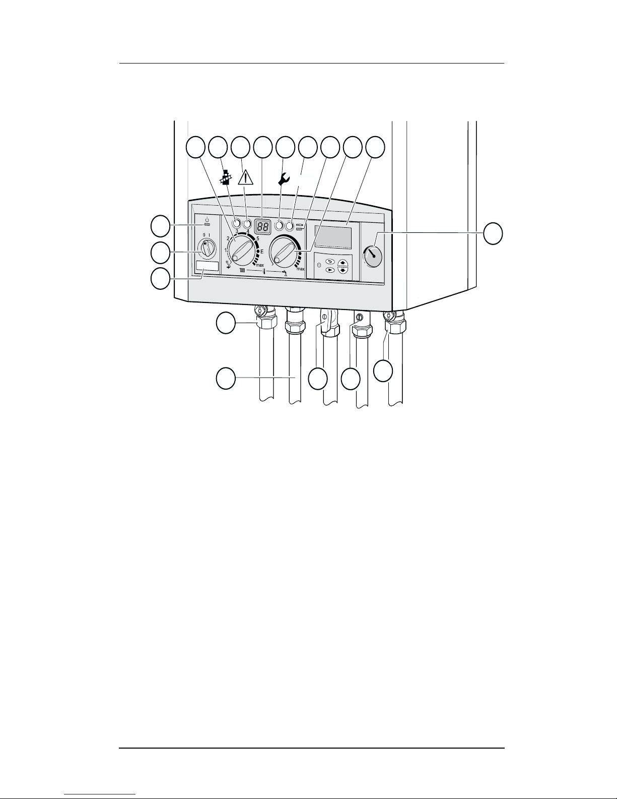
2 Controls
Controls
364
135
295
61
365136
170
171
317 366 367
ECO
172
310363
173
400
8.1
170
6 720 610 598 - 01.2O
Fig. 1
8.1 System Pressure gauge
61 Reset button
135 Master switch
136 Central heating temperature control
170 Service valves in CH flow and return
171 Hot water
172 Gas isolation valve (open)
173 Cold water inlet
295 Identification sticker
310 Hot water temperature control
317 Display
363 Indicator lamp for “burner on”
364 Indicator lamp for “off/on”
365 “Chimney sweep” button
366 Service button
367 “ECO” button
400 Text Display
6 720 610 604 GB (03.06)
11
Page 64
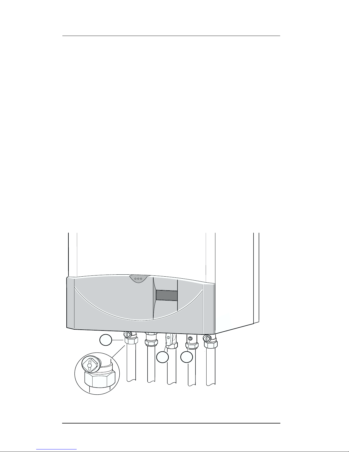
Operating the Appliance
3 Operating the Appliance
3.1 Preparation
Turn on the gas cock (172).
B Press in the handle and turn it anti-clo ckwise as far as the stop
(when handle is in line with direction of flow, the cock is open).
Central heating system valves (170)
B Using a spanner, turn square nut until groove is in line with
direction of flow (see detail).
Groove at right angles to direction of flow = off.
Cold water inlet valve (173)
B Turn handle so that it is in line with direction of flow.
When handle is at right angles to direction of flow, the valve is
closed.
170
172
173
Fig. 2
12
6 720 610 598-02.2O
6 720 610 604 GB (03.06)
Page 65
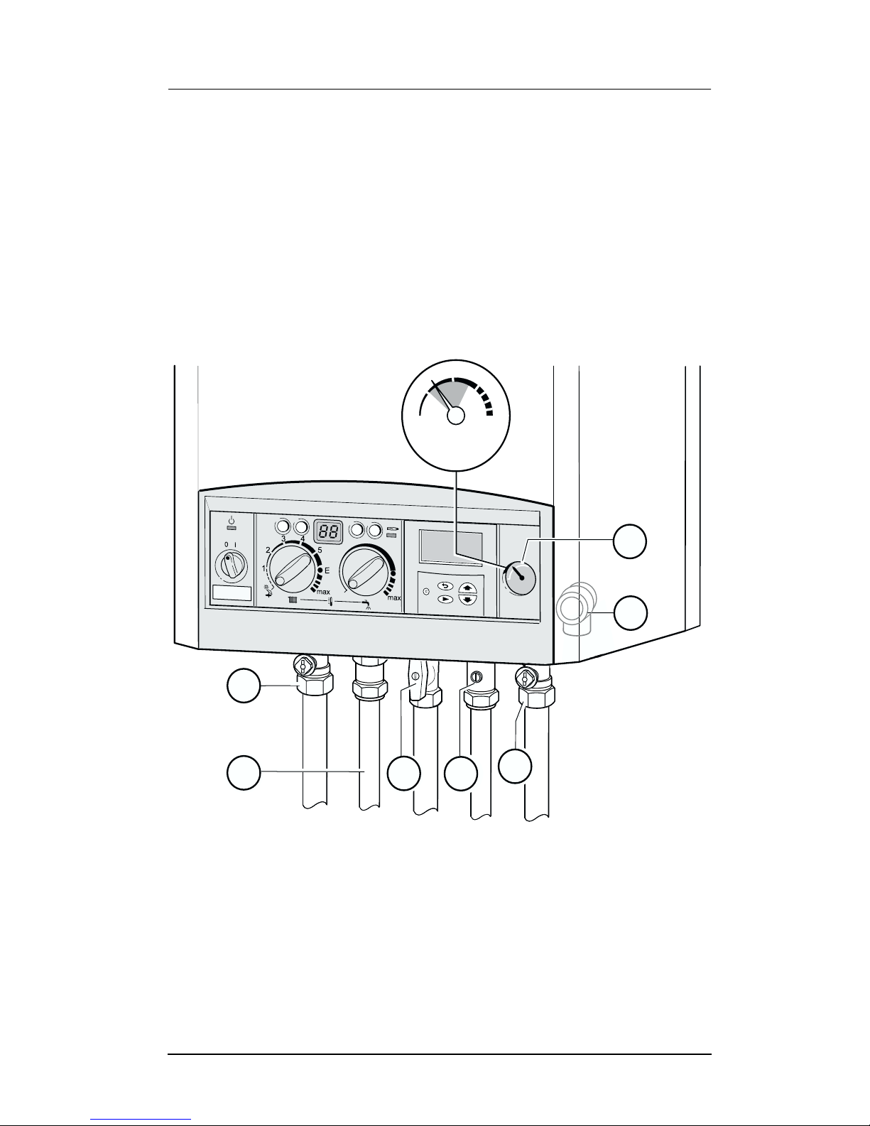
Operating the Appliance
Check the central heating system pressure
B The pointer on the pressure gauge (8.1) should be about 1 bar.
B If the pointer is below 1 bar (when the system is cold), top up
the system with water until the pointer is 1 bar. Your installer
will have shown you how to do this.
B The maximum operating pressure of 2.5 bar at maximum
central heating flow temperature must not be exceeded. If the
pressure increases to 3 bar then the relief valve (15) opens.
2
1
3
170
171
172
0
bar
4
8.1
15
173
170
6 720 610 598 - 03.2O
Fig. 3
6 720 610 604 GB (03.06)
13
Page 66
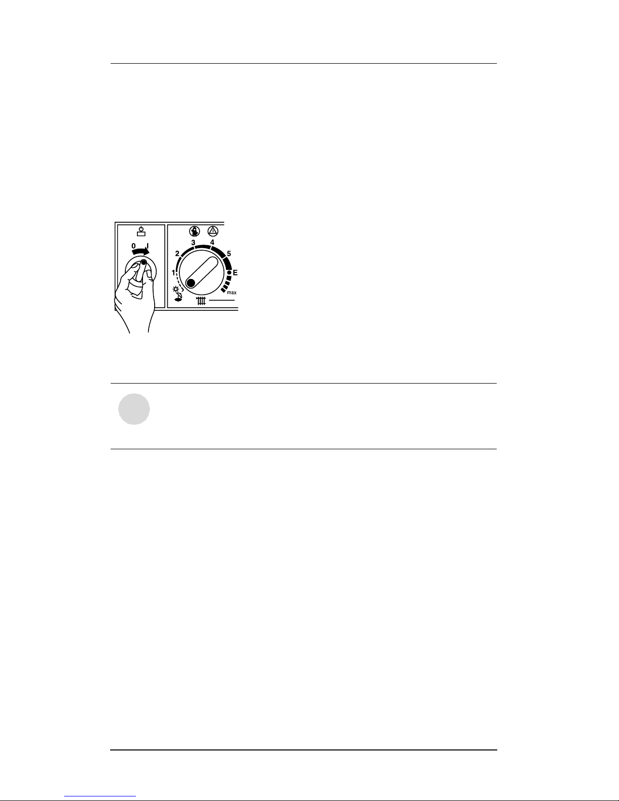
Operating the Appliance
3.2 Switching the Appliance On/Off
Switching on
B Switch on the appliance at the master switch (I).
The indicator lamp shows green and the display will show the
central heating flow temperature, when the appliance is operating in the central heating mode.
6 720 610 333-04.1O
Fig. 4
If the display alternates between -II- and the cen-
i
The trap filling programme ensures that the condensation trap is
filled after the appliance has been installed or after the appliance
has been out of use for a long period. For that reason, the appliance remains at minimum heating output for 15 minutes.
Switching off
B Switch off the appliance at the master switch (0).
The green indicator lamp goes out. The optional timer will continue running until the emergency supply is exhausted.
tral heating flow temperature, the trap filling programme is active.
14
6 720 610 604 GB (03.06)
Page 67
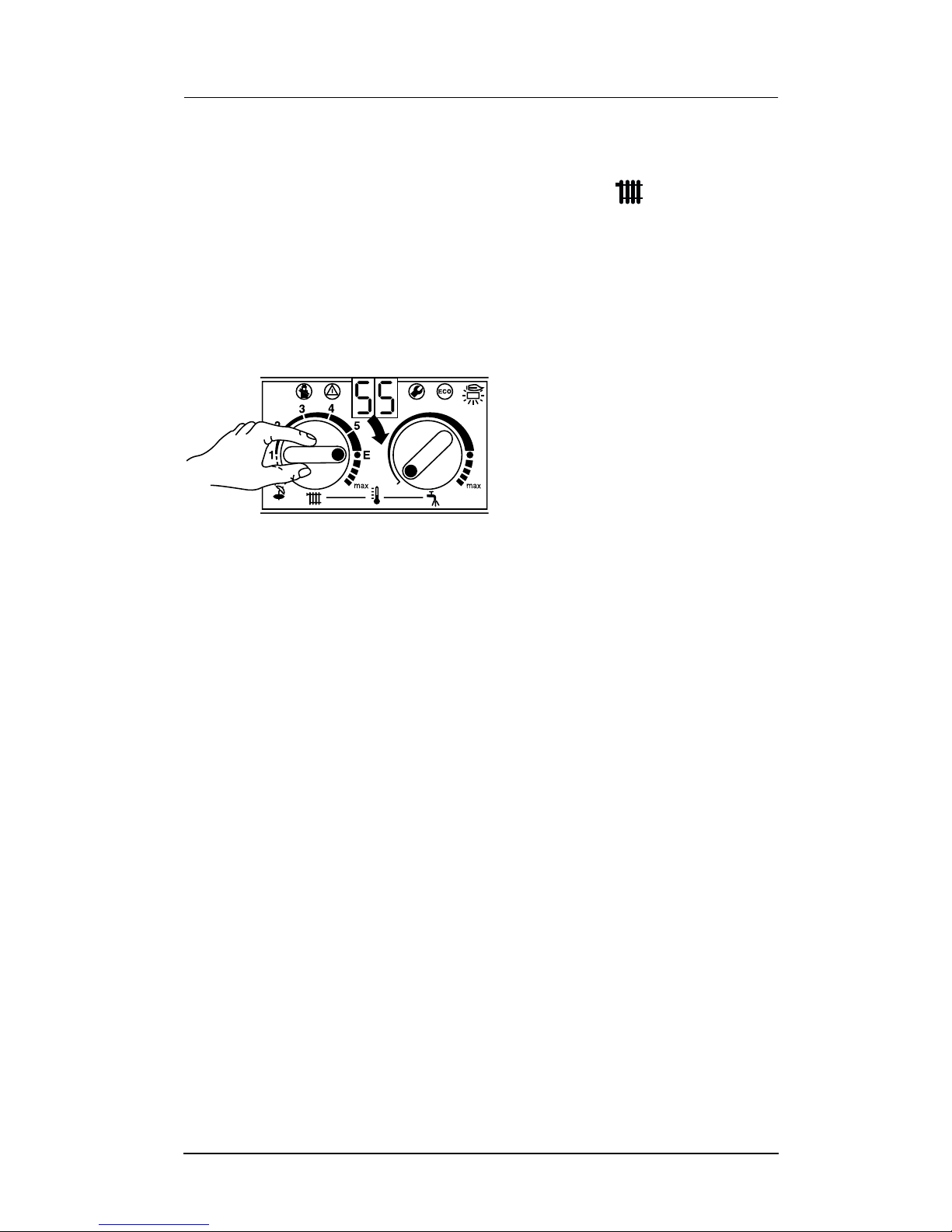
Operating the Appliance
3.3 Switching on the Central Heating
B Turn the central heating temperature control to the desired
level:
–“Min” setting: 35°C
– Low-temperature heating: setting “E” (approx. 75°C)
–“Max” setting: 88°C
When the burner is lit, the red indicator lamp is illuminated.
6 720 610 333-05.1O
Fig. 5
3.4 Controlling Central Heating
B Set the timer to the correct time.
B Set room thermostat to the desired room temperature.
B Set temperature driven control unit, if fitted. Refer to the
instructions with the control.
B Set the thermostatic radiator valves to the desired settings.
6 720 610 604 GB (03.06)
15
Page 68
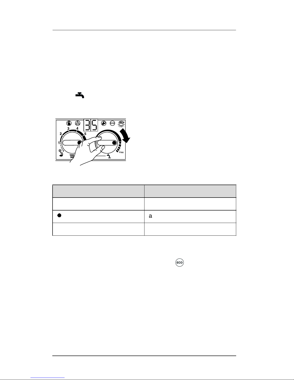
Operating the Appliance
3.5 Combination Boilers: Setting the Hot Water
Temperature
Hot water temperature
On combi models, the hot water temperature can be set to
between approx. 40°C and 60°C using the temperature
control .
The domestic hot water temperature is not shown on the display.
6 720 610 333-07.1O
Fig. 6
Control Setting Water Temperature
Anti-clockwise limit approx. 40°C
approx. 55°C
Clockwise limit approx. 60 °C
Table 2
“ECO” button
By pressing and holding the “ECO” button , until the display
lights, you can switch between Comfort mode and Economy
mode.
Comfort mode: button is not lit (factory setting)
The appliance is held constantly at the set temperature. This
means that hot water is available almost instantaneously at the
tap. Consequently the appliance will switch on at intervals, even if
no hot water is being drawn.
16
6 720 610 604 GB (03.06)
Page 69
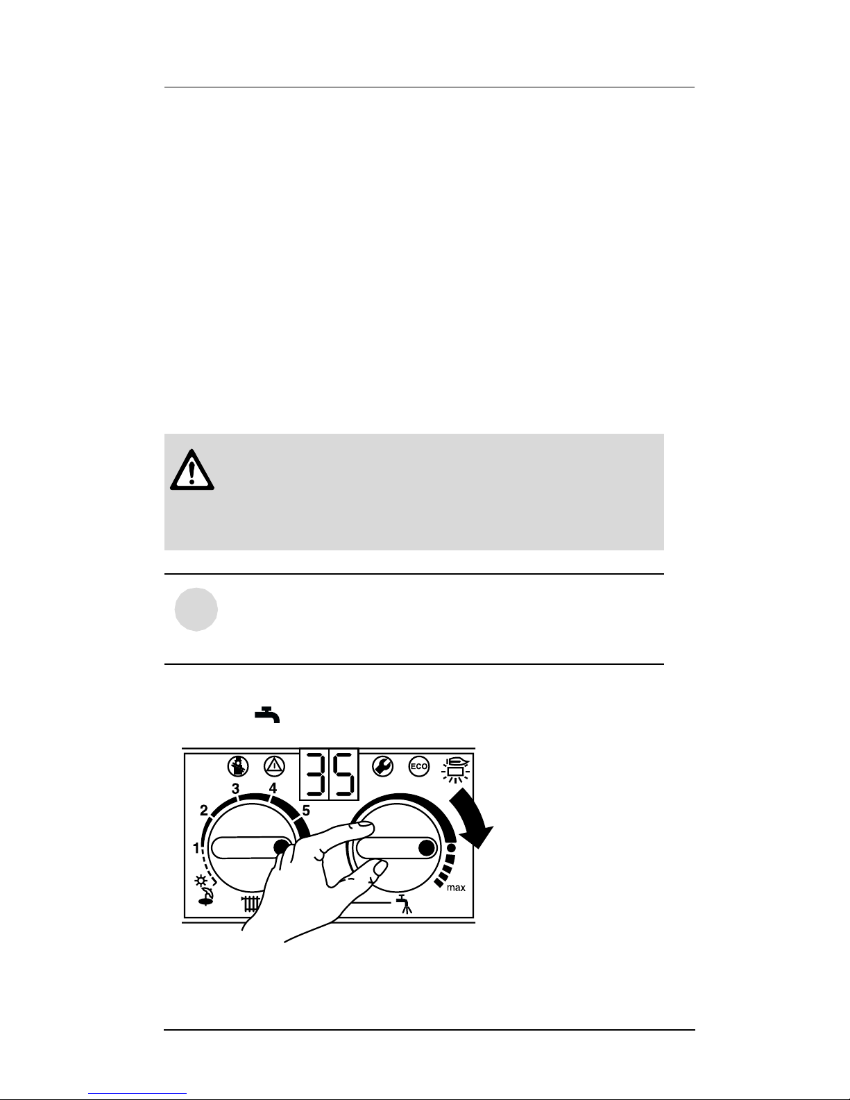
Operating the Appliance
ECO mode with demand detection, button is lit
The demand detection function enables maximum gas and water
economy.
Briefly turning a hot water tap on and then off again signals
demand to the appliance which then heats up the water to the set
temperature.
Hot water is thus available in about 1 minute.
ECO mode, button is lit
Water is not heated up until hot water is drawn. This means that
there is a longer waiting period before hot water is available.
3.6 System boiler with Storage Tank
B Do not set the temperature higher than
60°C for normal operation.
B Only use temperatures of up to 70 °C tempo-
rarily for thermal disinfection purposes.
With the text display you can additional set hot
i
B Set the hot water temperature by means of the temperature
control on the appliance.
water charging times or times and temperatures.
Fig. 7
6 720 610 604 GB (03.06)
6 720 610 333-07.1O
17
Page 70
Operating the Appliance
Control Setting Water Temperature
Anti-clockwise limit approx. 10°C
(frost protection)
l approx. 60°C
Clockwise limit approx. 70°C
Table 3
ECO button
Pressing and holding the ECO button , until it lights up
switches from Comfort mode to ECO-mode.
Comfort mode, ECO button is not lit (factory setting)
In Comfort mode the hot water tank has priority. The hot water cylinder is first heated up to the set temperature. The appliance then
switches to central heating mode.
ECO mode, button is lit
In ECO mode the appliance switches between central heating
mode and cylinder charging mode every 12 minutes.
3.7 Summer Mode, Hot Water Only
(Combi Appliances)
With room temperature controller
B Turn temperature control on the appliance anti-clockwise
as far as the stop.
The central heating is now turned off. The hot water function
and the mains power supply for the heating programmer and
timer remain switched on.
18
6 720 610 604 GB (03.06)
Page 71

Operating the Appliance
3.8 Frost protection (Combi Appliances)
B Leave master switch switched on.
If the appliance is to be left for long periods switch the central
heating on and set the room temperature controller at 6°C.
B Add a suitable anti-freeze fluid to the water in the central heat-
ing system.
Suitable products are available from Betz-Dearborn Tel.: 0151
4209563, Fernox Tel.: 01799 550811 and Salamander Tel.:
0121 378 0952.
3.9 Fault Condition
In the unlikely event of a fault occuring while the appliance is in
operation:
The display and the text display then shows a fault code and the
button may also flash.
If the button flashes:
B Press and hold the button until the display shows “––”.
The appliance will then start up again and the display will show
the central heating flow temperature.
If the button does not flash:
B Switch the appliance off and then on again at the master
switch.
The appliance will start up again and the central heating flow
temperature will be displayed.
If the fault remains and can not be cleared:
B Call British Gas for assistance, giving a description of the fault
and, if possible, the fault code from the facia display.
6 720 610 604 GB (03.06)
19
Page 72
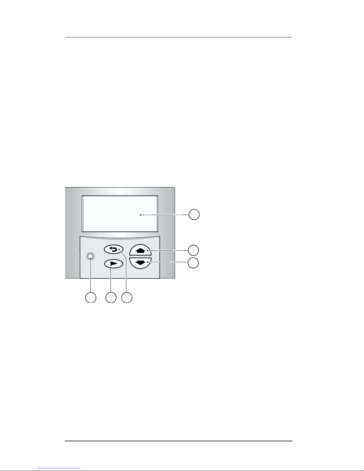
Text Display
4Text Display
4.1 General Description
• The text display is used to display information about the appli-
ance and the system and to alter the settings displayed.
• Once the appliance has been in operation for one day, the text
display module has a power buffer period of about 10 hours
during which it will run without the mains power supply. After
that period has elapsed, the clock function shuts down but all
other settings are retained.
4.2 Programming
a
C
b
c
6 720 610 337-08.1R
e
f
Fig. 8 Controls
a Display
b “Up”/“More” button
c “Down”/“Less” button
d “Back” button
e “Next” button
f “Delete” button
The standard display shows the following information:
d
•Time
• Room temperature (if TR 2 connected)
• CH flow temperature
20
6 720 610 604 GB (03.06)
Page 73
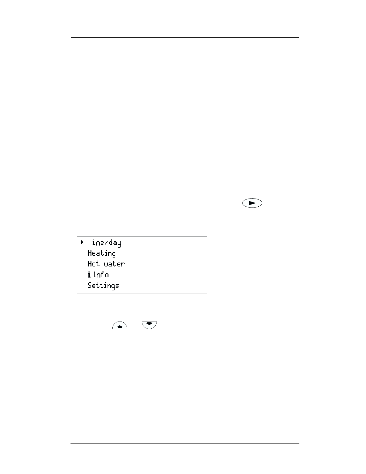
Text Display
• Domestic Hot Water temperature (System boiler if a Storage
Tank is accorded).
Additional indication if a special programme is active:
•x holidays
• Hot water immediately
• Constant on (comfort, if TR2 is not connected)
• Constant off (economy, if TR2 is not connected).
Other special operating modes may be displayed during commissioning, servicing, etc.
The programming procedure is described in detail below using
the clock function as an example:
B To start programming, press any button, e. g. .
The display lighting switches on and the main menu is displayed:
T
/holidays
6 720 610 598-04.2O
Fig. 9 Main menu
B Use the or button to move the cursor arrow on the
left of the menu so that it points to the desired menu item.
In this example, the cursor is positioned next to the menu item
Time/day/holidays.
6 720 610 604 GB (03.06)
21
Page 74
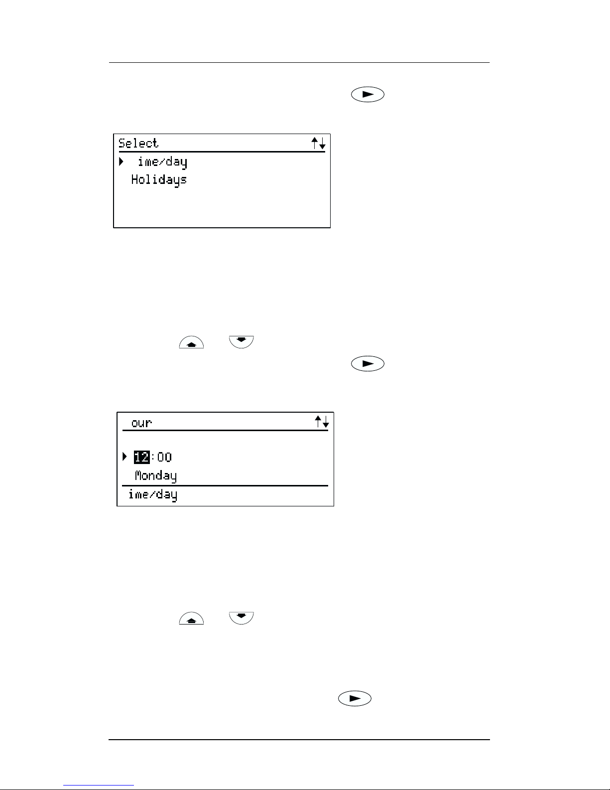
Text Display
B Confirm the selection by pressing the button.
The corresponding submenu is displayed:
T
6 720 610 598-05.2O
Fig. 10 Submenu: Time/day
In the submenus, the top line indicates what action is required.
The bottom line shows the previous menu level, if applicable (see
Fig. 10).
B Use the or button to select Time/day.
B Confirm the selection by pressing the button.
The corresponding submenu is displayed:
H
T
6 720 610 598-06.2O
Fig. 11 Setting the hour
When settings are being entered, the setting to be altered is indicated on the top line. In addition, the setting being altered is displayed with a dark background.
B Use the or button to set the hour.
– Press and release to change the display by one unit at a
time
– Press and hold to change the display rapidly
B Confirm the setting by pressing the button.
22
6 720 610 604 GB (03.06)
Page 75
Text Display
B Use the or button to set the minutes.
B Confirm the setting by pressing the button.
B Use the or button to set the day of the week.
B Press the button to confirm the setting. The cursor then
returns to the top line.
-or-
B Press the button to confirm the setting and return to the
previous menu (Fig. 9 page 22).
-or-
B Do not press any other buttons for 15 minutes.
4.2.1 Deleting a setting
Either overwrite the setting or press the button to delete it.
B Find the setting to be deleted.
B Press and release the button.
The display shows --:--
4.2.2 Resetting all parameters to their original settings
The hours of service can not be reset to 0.
C
C
i
B Press and hold the button for more than 15 seconds.
After about 5 seconds, the following message appears on the
display:
ATTENTION
Delete all parameters
in x seconds
Once the reset has been completed, the following message is
C
displayed:
Please wait... Initialising
6 720 610 604 GB (03.06)
23
Page 76
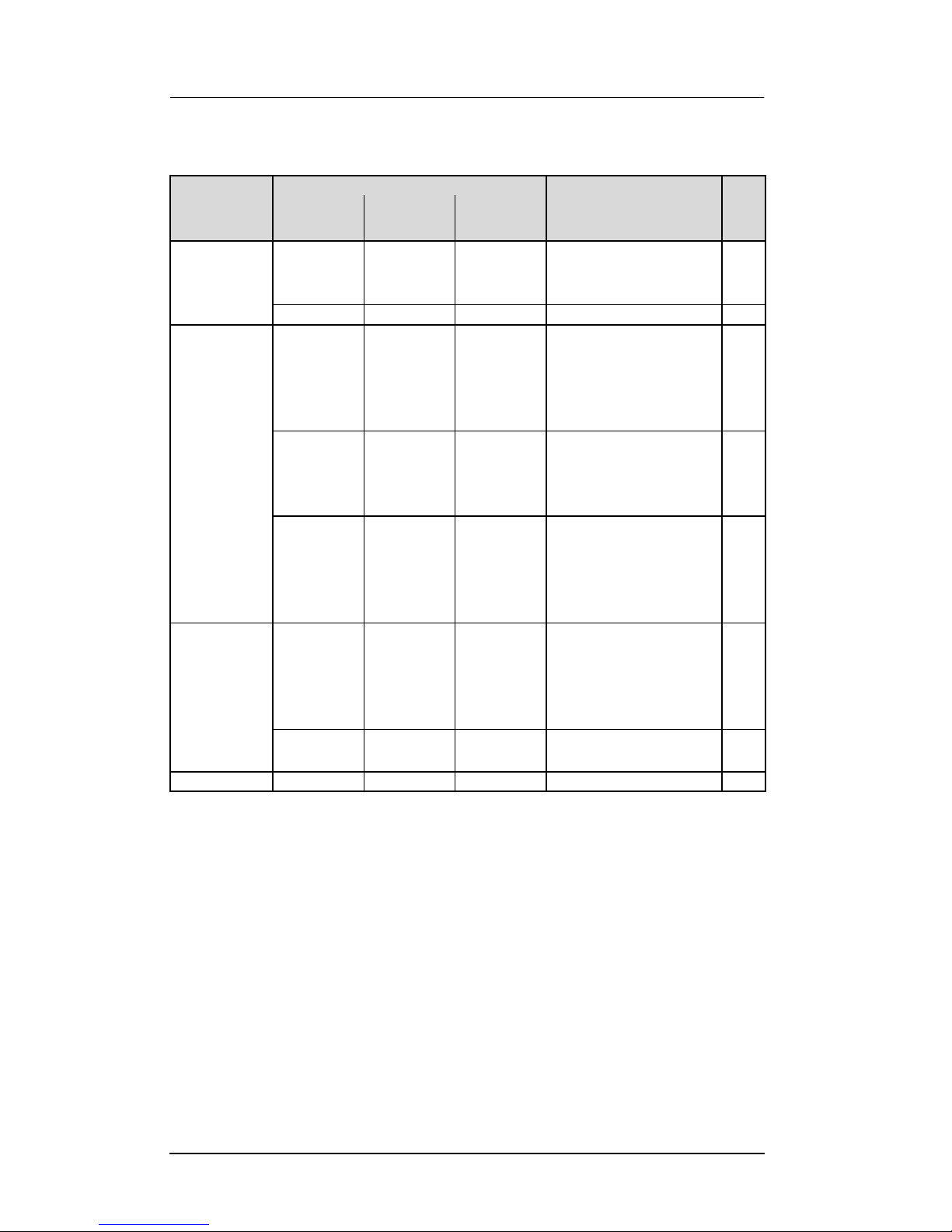
Text Display
4.3 Menu structure
Submenu
Parameters to
Main menu 1. 2. 3.
Time/day/holidays
Heating Heating
Hot water Hot water
Info---- 32
Time/day - - - Hours
Holidays - - Days holiday 25
--- Day
program
Set economy temp.
(if TR2 is
connected)
Manual
(if TR2 is
not connected)
program
Hot water
immediately
- - 5...30°C 28
- - - Automatic
--- Day
- - Off/On 31
change/select
- Minutes
- Day of week
- 1st operating mode
- 1st switching point
...
- 6th switching point
- Constant on
(comfort)
- Constant off
(economy)
- 1st operating mode
- 1st switching point
...
- 6th switching point
Page
25
27
29
31
24
6 720 610 604 GB (03.06)
Page 77
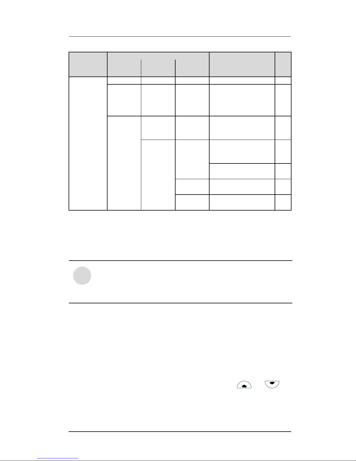
Text Display
Submenu
Parameters to
Main menu 1. 2. 3.
Settings Heating - - Optimum Start Off/On 33
Hot water
(System
boiler-models)
Service Display
- - Only charging times/
-- 33
service
param.
Further
options
Language -English/
Operating
times
Fault
history
change/select
30
times and temperatures
34
-Français/
-Deutsch
-Time correction
-LCD contrast
-34
-35
34
34
Page
4.4 Setting the time/day
4.4.1 Setting the time and day
For details of how to set the time and day, refer to page 21.
Changing winter and summer time:
i
B Only adjust the clock! Do not alter the switching
points (for heating, economy, etc.).
4.4.2 Holidays
In the Holiday programme, the central heating runs in Economy
mode and the hot water is switched off (frost protection function
remains active).
B From the main menu, select Time/day/holidays, and from the
first submenu select Holidays.
B Enter the number of days holiday by pressing or
(max. 99 days holiday).
After the set number of days, the text display module automat-
6 720 610 604 GB (03.06)
25
Page 78

Text Display
ically cancels Economy mode at midnight on the last day and
returns to Automatic mode.
The day on which you enter the days holiday
i
To cancel Holiday mode early:
B In the Holidays submenu:
counts as the first day of the holiday, i.e. the unit
starts the holiday program immediately. Only include the day on which you are returning if you
don’t want the heating to return to the normal program on that day!
Press the button until the display shows 0 .
C
26
6 720 610 604 GB (03.06)
Page 79

Text Display
4.5 Heating
4.5.1 Heating program
Basic setting (Automatic mode)
• The appliance switches automatically between normal heating,
Economy mode and Frost protection mode according to the
timer settings entered.
• Basic setting:
– Heating starts at 6:00 am
– Economy starts at 10:00 pm
Setting options
• Maximum of six switching points per day with three different
operating modes (Heating, Economy, Frost protection).
• Same times for Monday to Friday.
• Same times for Saturday and Sunday.
• Different times for every day.
Setting switching times and operating mode
B From the main menu select Heating and then from the first
submenu, select Heating program.
B Select Monday - Friday, Saturday and Sunday or an individual
day of the week.
– Monday - Friday: to have “Heating” and “Economy” or
“Frost protection” switching on at the same times every
weekday.
– Saturday - Sunday: to have “Heating” and “Economy” or
“Frost protection” switching on at the same times Saturday
and Sunday.
– Individual day of the week (e. g. Thursday): to have the rel-
evant program always switching on at the specified time on
that day of the week, i.e. “Heating”, “Economy” or “Frost
protection” at the same time every Thursday.
6 720 610 604 GB (03.06)
27
Page 80
Text Display
B Press . The display shows Set 1. operating mode.
B Set the desired first operating mode (Heating, Economy or
Frost protection).
B Press . The display shows Set 1. time period.
B Set the desired first time period.
B Press . Set the following operating modes and time peri-
ods as described for the first.
B If necessary: select the next day and enter the operating
modes and timer periods as described above.
If the settings for a particular day of the week
i
are different from the settings for the other
days, then if Monday -Friday or Saturday
and Sunday is selected, the display shows
--:--, i.e. there are no common switching points
for those options.
Timer periods and operating modes are you do not wish to
change can be skipped by pressing .
4.5.2 Setting the Economy temperature (if TR2 is connected)
This option allows you to set the room temperature for Economy
mode (Off (Economy)).
This function is only active if:
• Automatic mode or Economy mode is set on the TR 2 room
thermostat.
B From the main menu, select Heating and then from the first
submenu, select Set Economy temp..
B Use the or button to set a temperature between 5
and 30 °C.
28
6 720 610 604 GB (03.06)
Page 81

Text Display
4.5.3 Manual operating mode (if TR2 is not connected)
For selecting an operating mode that is different from the one set
in the heating programme (Automatic mode).
• You can choose between Automatic, Constant on (comfort)
and Constant off (economy).
• The manually selected operating mode starts immediately.
• Constant off (economy) and Constant on (comfort) are automatically reset at 00.00 (midnight).
• To cancel the manually selected operating mode:
– select the relevant menu and then press the button,
C
– or select a different operating mode,
–or set Holiday.
B From the main menu select Heating and then from the first
submenu Manual select required mode.
6 720 610 604 GB (03.06)
29
Page 82

Text Display
4.6 Hot water
General description
• Combi models only: The basic settings provide a straightfor-
ward timer programme: enabled from 5:00 am, disabled from
10:00 pm. The ECO button must not be lit (Comfort mode).
• System models (with Storage Tank): The basic settings pro-
vide a timer programme: enable from 5:00 am, disable from
10:00 pm. With the menu Hot water (see page 33) you can
choose a timer-/temperature programme with the basic settings: 60°C from 5:00 am, 10°C from 10:00 pm.
30
6 720 610 604 GB (03.06)
Page 83

Text Display
4.6.1 Hot water program
• Up to six switching points per day can be set.
• There are two operating modes: Blocked and Released.
B From the main menu, select Hot water and then from the first
submenu, select Hot water program.
B Set the days of the week, Blocked/Released (operating mode)
in the same way as for the switching points and modes for
heating as described on page 27.
4.6.2 Hot water immediately (System models)
• Hot water immediately ON:
– Comfort mode is active for 2 hours.
• Comfort mode is active for 2 hours: normal automatic pro-
gram (Hot water mode according to timer programme
entered).
B From the main menu, select Hot water and then from the first
submenu, select Hot water immediately.
B Press or to switch Hot water immediately on or off.
6 720 610 604 GB (03.06)
31
Page 84
Text Display
4.7 i Info
B Select Info from the main menu.
You can view the following information:
Display text Description
Room temperature
(if TR 2 connected)
Required room temperature (if TR 2 connected)
Operating mode
(if TR 2 connected)
Max. flow temp. Maximum CH flow temperature set on
Actual flow temp. Actual CH flow temperature
Required flow temp. Required CH flow temperature
Max HW temp. Maximum permissible hot water out-
Required HW temp. Required hot water temperature
Current temperature in the room
where TR 2 is installed
Required temperature in room where
TR 2 is installed
E. g. Heating, Economy in Automatic
mode
or
Economy, Heating, Frost protection in
manual mode
the temperature control for CH flow
flow temperature
Actual HW temp. Actual hot water outflow temperature
Storage Tank charge
released or blocked
Storage Tank charge on
or off or Storage Tank
charge afterrunning
Boiler operat. mode
winter/ summer
Burner on/off Indicates whether the burner is alight
Pump on/off Indicates whether the integral pump is
32
Shows, if hot water is released or
blocked
Shows, if hot water is on or off, or if
the pump for the Storage Tank afterrunning is on
Indicates which mode the CH flow
temperature control is set to
or not
switched on or off
6 720 610 604 GB (03.06)
Page 85
Text Display
4.8 Settings
4.8.1 Heating (if TR 2 is connected)
Optimum Start
B From the main menu, select Settings and from the first sub-
menu, select Heating.
B Press or to switch Optimum Start on or off.
4.8.2 Hot Water (Storage Tank, System boiler models only)
The text display can control the hot water either with Times and
temperatures or only times.
• Times and temperatures: One can choose up to six different
times with temperatures, see page 30 “Hot water”.
• Only times: During that times the Storage Tank will be
charged to the choosed temperature.
B From the main menu, select Settings and from the first sub-
menu select hot water.
B Press or to switch Times and temperatures or only
times.
Turn the hot water temperature control al-
i
4.8.3 Service
Displaying service functions
This option displays various current settings and statuses of the
electrically controlled appliance and system components for the
benefit of the heating engineer.
ways higher than the temperature at the text
display is choosen.
6 720 610 604 GB (03.06)
33
Page 86

Text Display
Service parameters
Language
Available languages are: English, Français (French), Deutsch
(German).
B From the main menu, select Settings, from the first submenu
select Service, from the Second submenu select Further
options, and from the third submenu select Language.
B Press or to select the desired language.
Two other supplementary functions can be selected from the third
submenu Language:
• Time correction
•LCD contrast.
Time correction:
B Press and hold the button (about 5 seconds) until the
display shows Time correction and LCD contrast.
B Press or to select Time correction.
B Press the button. The display shows Change value.
B Press or to set the number of seconds in 24 hours.
Basic setting: “+ 0 s”
LCD contrast:
B Press and hold the button (about 5 seconds) until the
display shows Time correction and LCD contrast.
B Press or to select LCD contrast.
B Press the button. The display shows Change value.
B Press or to adjust the LCD contrast.
Basic setting: e. g. “47”
Operating times
This option shows the hours of service (appliance, burner and hot
34
6 720 610 604 GB (03.06)
Page 87

Text Display
water) since commissioning.
B From the main menu, select Settings, from the first submenu
select Service, from the Second submenu select Further
options, and from the third submenu select Operating times.
Fault history
This option displays any faults that have occurred for the information of the service engineer. The first fault displayed may still be
active. Any other faults displayed are no longer active.
B From the main menu, select Settings, from the first submenu
select Service, from the Second submenu select Further
options, and from the third submenu select Fault history.
6 720 610 604 GB (03.06)
35
Page 88
Text Display
4.9 Individual timer programmes
Heating periods for central heating
Switching point 1. 2. 3. 4. 5. 6.
Status
Monday
Tuesday
Wednesday
Thursday
Friday
Saturday
Sunday
Enable/disable hot water function
Switching point 1. 2. 3. 4. 5. 6.
Operating mode
Time
Operating mode
Time
Operating mode
Time
Operating mode
Time
Operating mode
Time
Operating mode
Time
Status
Monday
Tuesday
Wednesday
Thursday
Friday
Saturday
Sunday
36
Operating mode
Time
Operating mode
Time
Operating mode
Time
Operating mode
Time
Operating mode
Time
Operating mode
Time
6 720 610 604 GB (03.06)
Page 89
5 Fault finding
Problem Cause Remedy
Fault finding
Desired room
temperature is not
reached
Desired room
temperature
exceeded by large
amount
Temperature rises
instead
Thermostatic
valve(s) set too
low
Temperature control for CH flow
set too low
Air trapped in
heating system
Radiators are too
hot
Clock is incorrectly set
Increase thermostatic valve setting(s)
Increase CH flow
temperature control setting
Bleed radiators
and heating system
Turn down thermostatic valves
Check setting
of falling
Room temperature too high in
Economy mode
No display or display unit does not
respond
Storage Tank
doesn’t warm up
6 720 610 604 GB (03.06)
Building retains
heat well
Momentary power
failure
Temperature control is too low
Start Economy
mode sooner
Switch off appliance at master
switch, wait a few
seconds and
switch on again
Turn the temperature control to the
desired temperature
37
Page 90

Tips on saving energy
6 Tips on saving energy
Heating economically
The boiler is designed to provide a high level of comfort while
keeping gas consumption and the resulting environmental effect
as low as possible. The gas supply to the burner is controlled
according to the level of demand for heat. The boiler continues to
operate with a low flame if the demand for heat reduces. The technical term for this process is modulating control. Modulating control keeps temperature fluctuations small and provides even
distribution of heat throughout the home. This means that the
boiler may stay on for relatively long periods but will use less gas
than an appliance that continually switches on and off.
Central heating systems with room thermostats/thermostatic
radiator valves
The central heating control on the boiler should be set to the maximum rated temperature of the central heating system or to position “E”, when the maximum central heating water temperature
obtained is 75°C.
The temperature can be set individually in each room (except primary room with the room thermostat) using the thermostatic radiator valves. If you wish to have a lower temperature in the primary
room than in the other rooms, leave the room thermostat at the set
temperature and turn down the radiator using the radiator valve.
Reduced-output operation
Considerable fuel savings can be made by slightly reducing the
room temperature. Lowering the temperature by 1 °C can bring
about energy savings of up to 5 %. However, it is not advisable to
allow any room temperature to fall below +15 °C. The room temperature for reduced-output mode can be set separately on the
room thermostat. Instructions are given in the control unit operating instructions.
38
6 720 610 604 GB (03.06)
Page 91

General Information
Hot water
A lower setting on the hot water temperature control can result in
considerable energy savings.
For combi appliances:
The on-demand activation using the ECO-button makes possi-
ble the maximum savings of gas and water.
Now you know how to heat your home economically with the RD
532i/RD 537i/RD 542i /RD 430i gas condensing boiler. If you
have any other questions, please contact your installer – or write
to us.
7 General Information
Cleaning the Outer Case
Wipe down the outer case with a damp cloth. Do not use abrasive
or caustic cleaning agents.
Appliance details
If you ever need to call Customer Service it helps us a great deal
if you can provide precise details of your appliance.
The information is printed on the appliance identification plate/
sticker (see page 11, item 295).
Your installer will have completed the Benchmark “log-book” giving details of the boiler together with name, address and registration number. Have the “log-book” to hand when calling a Service
Engineer.
6 720 610 604 GB (03.06)
39
Page 92

Maintaining your appliance
8 Maintaining your appliance
Your new RD 532i/RD 537i/RD 542i /RD 430i gas-fired appliance represents a long-term investment in a reliable, high quality
product.
In order to realise its maximum working life, and to ensure it continues to operate at peak efficiency and performance, it is essential that your boiler receives regular, competent servicing and
maintenance checks beyond the initial 2 year guarantee period.
To arrange for a British Gas three star cover agreement please
call 08459605040.
9 Service
If your RD 532i/RD 537i/RD 542i /RD 430i appliance should fail
to operate correctly or requires servicing please call British Gas
on: 08459605040.
40
6 720 610 604 GB (03.06)
Page 93

Fault or breakdown
10 Fault or breakdown
This product is supported in the UK by Worcester Heat Systems
Ltd. – part of the Bosch Group.
A specialist factory trained field SERVICE ENGINEER is available
to attend a breakdown or manufacturing fault occuring on this
appliance.
No charge will be made for parts and/or labour providing:
• An appliance fault is found and the appliance has been
installed within the past 24 months. Reasonable evidence of
this must be supplied on request.
A call-out charge will be made where:
• The appliance has been installed for over 24 months.
OR
• Our Field Service Engineer finds no fault with the appliance
(see NOTE).
OR
• The cause of breakdown is misuse or with other parts of your
plumbing/heating system, or with equipment not supplied by
Worcester.
NOTE: No appliance fault is found on over 30 % of all service call
outs.
If in doubt contact our British Gas on 0845 9 60 50 40.
IN THE EVENT OF AN APPLIANCE FAULT OR BREAKDOWN
please contact your Service Centre (see over). Your service
administrator will arrange for an engineer to call with the minimum
of delay; under normal circumstances this will be within the period
1-3 working days (excluding weekends) for priority breakdown situations (no hot water and/or heating service).
INVOICES FOR ATTENDANCE AND REPAIR WORK CARRIED
OUT ON THIS APPLIANCE BY ANY THIRD PARTY WILL NOT
BE ACCEPTED.
6 720 610 604 GB (03.06)
41
Page 94

Your guarantee
11 Your guarantee
This appliance is guaranteed against faulty material or workmanship for a period of 24 calendar months from the date of installation subject to the following conditions and exceptions.
• That during the currency of this guarantee any components of
the unit which are proved to be faulty or defective in manufacture will be exchanged or repaired free of material charges and
free of labour charges by Worcester Heat Systems Limited.
• That the householder may be asked to prove the date of installation, that the appliance was correctly commissioned and,
where appropriate, the first 2 year service has been carried out
to the satisfaction of Worcester Heat Systems Limited when
requested.
• That any product or part thereof returned for servicing under
the guarantee any components of the unit which are proved to
be faulty guarantee must be accompanied by a claim stating
the Model, Serial Number, Date of Installation.
• That Worcester Heat Systems Limited will not accept responsibility for damage caused by faulty installation, neglect, misuse
or accidental damage, the non observance of the instructions
contained in the Installation and Users Instructions Leaflets.
• That the appliance has been used only for normal domestic
purposes for which it was designed.
• That this guarantee applies only to equipment purchased and
used in Great Britain.
This guarantee is given in addition to all your normal statutory
rights.
42
6 720 610 604 GB (03.06)
Page 95

Guarantee registration
12 Guarantee registration
You should complete and return the postpaid Guarantee Registration Card within 14 days of purchase.
The card will register you as the owner of your new RD 532i/RD
537i/RD 542i /RD 430i appliance and will assist us in maintaining
an effective and efficient customer service by establishing a reference and permanent record for your boiler.
This will not affect your statutory rights in any way.
Important:
For your own record:
Model
.......................................................................................................................
Serial number:.............................................................................................
(See identity label inside appliance casing)
Type/size:.....................................................................................................
Date of installation:....................................................................................
Check that the Benchmark “log-book” has been completed by
your installer or service engineer.
SERIAL NUMBER. Copy the number off the Guarantee Card.
6 720 610 604 GB (03.06)
43
Page 96
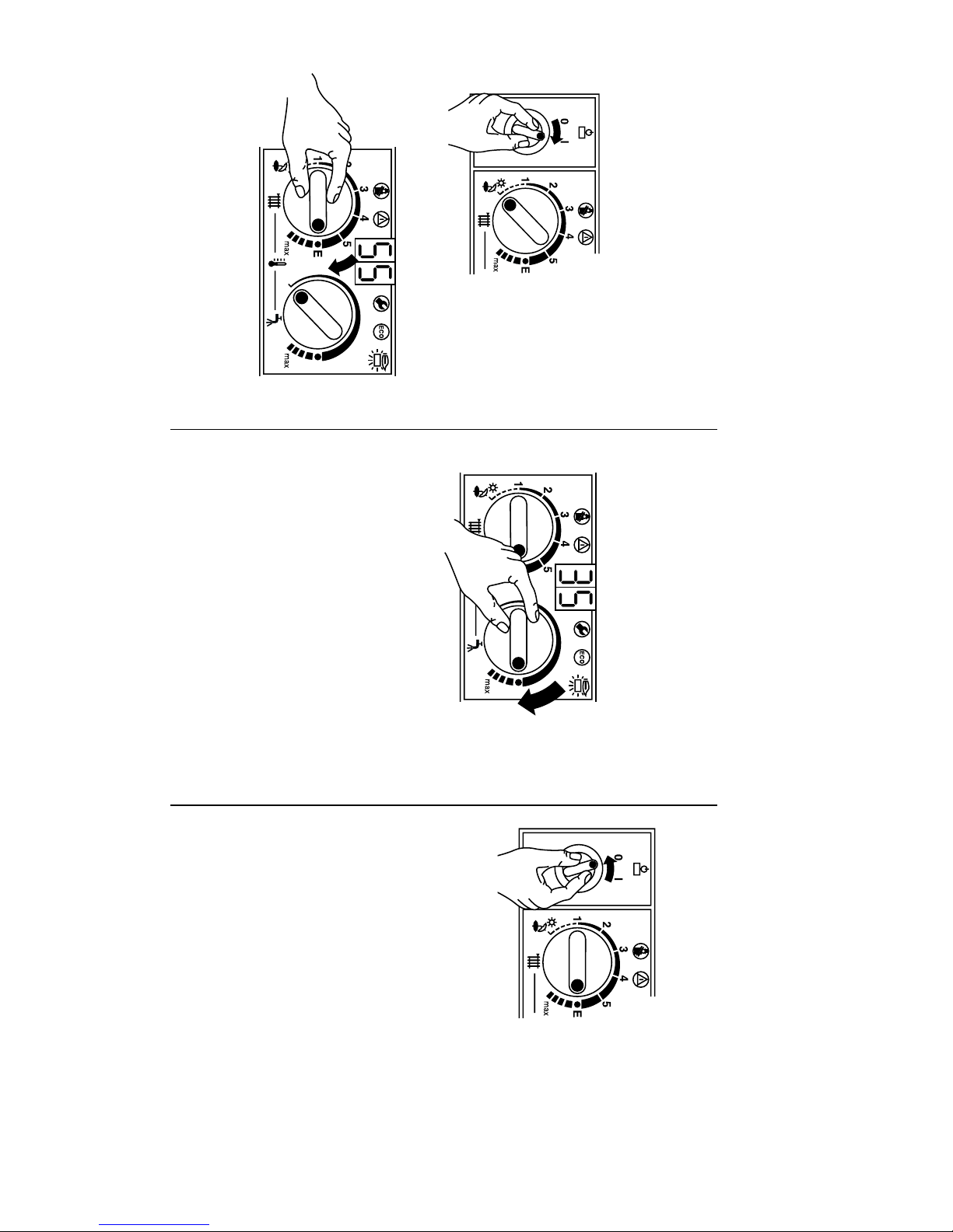
6 720 610 333-05.1O
Comfort mode
tions Quick Refer-
13 Operating Instruc-
Text Display
Set switching times and operating
Switching the central heating on
Switching on
ence
6 720 610 333-04.1O
mode within the text display.
Hot water temperaeture – Combi-
“ECO”-button lit –
Economy mode.
“ECO”-button not lit –
nation boiler only
6 720 610 333-07.1O
6 720 610 333-11.1O
Switching off
Fault Condition
Refer to page 19.
Page 97
Users Instructions and
Customer Care Guide
RD 532 Condensing boiler
RD 428 Condensing boiler
720 610 577- 01.10
6
ZWB 7-32 RD 532 GC-Number: 41 108 13
ZB 7-28 RD 428 GC-Number: 41 108 07
6 720 610 600 GB (03.06) OSW
Page 98

Contents
Contents
Excellence comes as standard 4
Safety precautions 5
1 General notes 6
2Controls 10
3 Operating the Appliance 11
3.1 Preparation 11
3.2 Switching the Appliance On/Off 14
3.3 Switching on the Central Heating 15
3.4 Controlling Central Heating 15
3.5 RD 532 Boilers: Setting the Hot Water Temperature 15
3.6 Summer Mode, Hot Water Only
(RD 532 Appliances) 17
3.7 Frost protection (RD 532 Appliances) 18
3.8 Fault Condition 18
4 Tips on saving energy 19
5 General Information 21
6 Maintaining your appliance 21
7 Service 22
2
6 720 610 600 GB (03.06)
Page 99

Contents
8 Fault or breakdown 23
9 Your Bosch guarantee 24
10 Guarantee registration 25
11 Operating Instructions Quick Reference 27
6 720 610 600 GB (03.06)
3
Page 100

Excellence comes as standard
Excellence comes as standard
Thank you for purchasing an RD 532/RD 428 condensing appliance.
The RD 532/RD 428 Series has been developed by the Bosch
Group and the strictest quality control standards are demanded
throughout every stage of production.
Indeed, the Bosch Group have led the field in innovative appliance
design and performance for many years.
The result is that your new RD 532/RD 428 appliance offers you
the very best of everything – quality, efficiency, economical running costs, proven reliability and value for money.
What’s more, you also have the assurance of our no nonsense
2 year parts and labour guarantee.
And it’s backed up by British Gas - Offering a complete maintenance scheme to keep your boiler operating at peak condition and
efficiency.
No wonder that more and more people are agreeing that when it
is gas, it has to be a British Gas/Scottish Gas Condensing appliance.
Benchmark
The “Benchmark” initiative is the new code of practice to encourage the correct installation, commissioning and servicing of
domestic central heating boilers and system equipment.
The “log-book” is a vital document that must be completed by the
installer at the time of installation. It confirms that the boiler has
been installed and commissioned according to the manufacturers
instructions.
Without the completion of the “log-book”, manufacturers may
refuse to respond to a call–out from a householder, who will be
advised that he or she must call back the installer, who has not fulfilled his obligations to record the information required by the initiative.
4
6 720 610 600 GB (03.06)
 Loading...