

Page 1
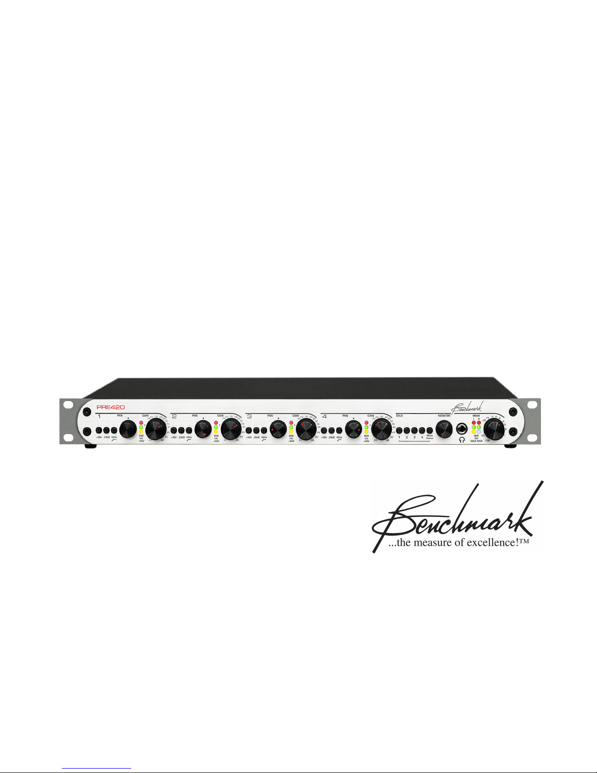
Benchmark PRE420
Instruction Manual
4-Channel Microphone Preamplifier/Mixer
Page 2

Safety Information
Voltage Selection
CAUTION: THE FUSE DRAWER INCLUDES
A VOLTAGE SELECTION SWITCH WITH
TWO SETTINGS: “110” AND “220”.
CHECK TO SEE THAT IT IS PROPERLY
CONFIGURED FOR YOUR LOCATION
BEFORE CONNECTING AC POWER.
Incorrect configuration may blow fuses or
cause erratic operation.
Repairs
CAUTION: DO NOT SERVICE OR REPAIR
THIS PRODUCT UNLESS PROPERLY
QUALIFIED. ONLY A QUALIFIED
TECHNICIAN SHOULD PERFORM
REPAIRS.
Fuses
CAUTION: FOR CONTINUED FIRE
HAZARD PROTECTION ALWAYS REPLACE
THE FUSES WITH THE CORRECT SIZE
AND TYPE (0.5A 250 V SLO-BLO
MM – LITTELFUSE® HXP218.500 OR
EQUIVALENT).
®
5 X 20
Modifications
CAUTION: DO NOT SUBSTITUTE PARTS
OR MAKE ANY MODIFICATIONS
WITHOUT THE WRITTEN APPROVAL OF
BENCHMARK MEDIA SYSTEMS, INC.
MODIFICATION MAY CREATE SAFETY
HAZARDS AND VOID THE WARRANTY.
NOTICE: CHANGES OR MODIFICATIONS
NOT EXPRESSLY APPROVED BY
BENCHMARK MEDIA SYSTEMS COULD
VOID THE USER'S AUTHORITY TO
OPERATE THE EQUIPMENT UNDER FCC
REGULATIONS.
Page 3

Contents
Safety Information 2
Voltage Selection 2
Repairs 2
Fuses 2
Modifications 2
Contents 3
Overview 4
Features 6
Connections 7
Microphone Inputs (1-4) 7
Balanced Outputs – Overview 7
Driving Unbalanced Loads 8
Output Signal Levels 8
Direct Outputs (1-4) 8
Control Room Outputs (L&R) 8
Main Outputs (L&R) 8
AC Power Entry Connector 8
Fuse Holder 8
Preamp Section 9
Preamp Overview 9
Input Topology 9
Microphone Gain Controls 9
Blocking RF, EMI, and Noise 9
Phantom Power Switches 9
Input Protection 9
MirrorPan™ Pan Controls 11
20 dB Pads 11
Terminating Unused Inputs 11
40 Hz High-Pass Filters 11
LED Meters – Direct Outputs 11
Solo Bus 12
Solo Switches 12
Stereo/Mono Solo Switch 12
Control Room Outputs 13
Control Room Mute Switch 13
Driving Unbalanced Loads 13
Monitor Fader 13
HPA2™ Headphone Output 14
“0-Ohm” Output Impedance 14
Headphone Performance 14
Mix Outputs 15
Driving Unbalanced Loads 15
Main Fader 15
LED Meters – Mix Outputs 15
Rack Mounting 16
Mounting Near Other Equipment 16
Performance Graphs 17
Frequency Response 17
High-Pass Filter - Frequency Response 18
Inter-Channel Phase Response 19
THD+N vs. Frequency 20
Wideband THD+N vs. Frequency 21
Equivalent Input Noise vs. Gain 22
Noise Spectrum 23
THD Spectrum at 1 KHz 24
THD Spectrum at 10 KHz 25
Specifications 26
Microphone Preamps 26
Direct Outputs 27
Control Room and Main Outputs 27
MirrorPan™ Constant-Power Pan Circuit 28
HPA2™ Headphone Amplifier 28
LED Status Indicators and Meters 29
AC Power Requirements 29
Dimensions 30
Weight 30
Regulatory Compliance 31
FCC Notice 31
RoHS Compliant Information 31
CE Certificate of Conformity 32
Warranty Information 33
Benchmark Extended Warranty 34
Calibration 35
Required Equipment 35
+48V Adjustment 35
Microphone Gain and Metering 35
Monitor Gain Balance 35
Microphone Pan Balance 35
Main Gain Balance 36
Peak LED Adjust – Main Outputs 36
Page 4

Overview
The PRE420 is a 4-channel microphone
preamplifier/mixer and is designed to achieve
the highest performance available in a
microphone preamplifier. The PRE420 is
designed for maximum transparency, wide
bandwidth, low-noise, low-distortion, and
superior RF immunity. It is well suited for the
most demanding applications in studios and
live venues.
The PRE420 is the next evolution of
Benchmark’s legendary MPS-420 microphone
preamplifier. We have improved the
performance while adding meters, a mix bus,
a solo bus, and an internal power supply. The
added features do not compromise the
performance of the classic Benchmark design.
In all respects, the PRE420 meets or exceeds
the performance of the MPS series preamps.
The PRE420 features an astonishingly lownoise stereo mix bus driven by Benchmark's
proprietary MirrorPan™ circuitry to achieve
precise, distortion-free, constant-power
panning. The mix bus allows pristine directto-stereo recording from up to 4
microphones. The balanced stereo outputs
are equipped with meters and a master level
control.
A solo bus allows monitoring of individual
microphones as well as any stereo or mono
mix of microphones. The solo bus is routed
to the balanced control room outputs and to
the headphone amplifier. The control room
outputs have a switch that enables mute on
headphone insertion.
The PRE420 includes the HPA2™ Benchmark's signature high-current, 0-Ohm
headphone amplifier. The HPA2™ is capable
of delivering the full performance of the
PRE420 into the difficult loading presented by
many headphones.
Each of the PRE420's four microphone inputs
includes switches for +48V Phantom power, a
20dB pad, and a 40Hz high-pass filter. The
PRE420 achieves outstanding performance
over a wide range of input levels. Gain is
controlled by matched 41-detent pots and is
adjustable over a range of 22dB to 60dB
(without pad), or 2dB to 40dB (with pad
enabled). The mix bus can provide an
additional gain of up to 6 dB.
The PRE420 has four direct outputs, two
control room outputs, and two stereo outputs.
All outputs feature low-distortion, highcurrent drivers that easily handle long cables
and other less-than-ideal loads.
A rugged 1 RU enclosure includes an internal
power supply that supports all international
voltages and has generous margins for overvoltage and under-voltage conditions. It
features a core-banded toroidal transformer
in a shielded enclosure.
The entire signal path of the PRE420 has a
generously wide bandwidth: 500 kHz. This
creates a significant demand for exceptional
RF filtering and shielding – a demand
Benchmark fulfills.
All signal paths in the PRE420 are
aggressively protected from RF and magnetic
interference. For example, a special
construction technique is employed with the
multi-layer printed circuit board to create a 3-
PRE420 Instruction Manual – rev. E Page 4
Page 5

dimensional shield surrounding the
microphone-level signal traces to block RF
interference. Also, the microphone-level
traces are arranged in a star-quad layout to
prevent magnetic interference. Benchmark's
innovative shielding and filtering techniques
have given Benchmark microphone-preamps
a proven track record for exceptional
performance in difficult, RF-intensive
locations.
This RF-immunity is coupled with ultra-low
distortion performance at high-frequencies,
beyond that of most mic-preamps, giving
your audio remarkable realism. With an
amazingly low THD+N of 0.00024% (see
specs), we encourage you to compare the
PRE420's performance specifications and
sonic performance with any other micpreamp.
Microphone pre-amplifier circuits usually
suffer from non-linear performance at ultrasonic frequencies. This non-linearity causes
inter-modulation distortion (IMD) components
that fold down to audible frequencies. Unlike
harmonic distortion (THD), IMD produces
distortion tones that are very un-natural and
non-musical. IMD also masks and alters the
subtle details of delicate high-frequency
transients such as those produced by bells.
Benchmark MPS series preamps have always
had outstanding high-frequency performance
as well as freedom from IMD. The PRE420
takes the Benchmark design one step further,
and achieves the lowest IMD that we have
ever measured in a microphone preamplifier.
We believe that you will enjoy the sonic
performance and features of the PRE420.
PRE420 Instruction Manual – rev. E Page 5
Page 6

Features
• Four Transformerless Microphone Inputs
• Four Balanced Direct Outputs (XLR)
• Balanced Left and Right Main Outputs (XLR)
• Balanced Left and Right Control Room Outputs (XLR)
• HPA2™ “0-Ohm” 1/4” TRS Headphone Output
• Precision-Matched Monolithic Low-Noise Transistor Quads on Each Microphone Input
• High-Current High-Speed Low-Capacitance Phantom Protection Circuits
• Fully Protected Against Phantom Hot-Plug and Cable-Shorting Scenarios
• Balanced Transformerless Inputs and Outputs
• +48v Phantom Power Switch on Every Microphone Input
• 40 Hz High-Pass Filter Switch on Every Microphone Input (12 dB/octave)
• 20 dB Pad Switch on Every Microphone Input
• Matched 41-Detent First-Stage Gain Controls on Every Microphone Input
• 60 dB Maximum First-Stage Gain, Adjustable to 70 dB
• 22 to 60 dB Gain (pad off), 2 to 40 dB (pad on)
• +27 dBu Maximum Input Level (with pad), +7 dBu (without pad)
• +29.5 dBu Maximum Output Level on all Balanced Outputs
• + 23.5 dBu Maximum Headphone Output Level
• MirrorPan™ Low-Distortion Constant-Power Pan Controls (1 per input channel)
• Solo Switches (1 per input channel)
• Mono/Stereo Solo Switch for Flexible Monitoring
• 41-Detent Control Room/Headphone Level Control
• 41-Detent Main Output Level Control
• Control Room “Mute on Headphone Insertion” Mode Switch (rear panel)
• Intensity Modulated Signal Presence LEDs (Green - 4 on direct outputs plus 2 on main outputs)
• +24 dBu Warning LED (Red – 4 on direct outputs plus 2 on main outputs)
• Solo Warning LED (Yellow)
• +48V Phantom Warning Indicators (Yellow - 1 per input channel)
• Power LED (Blue)
• Ultra-Quiet Linear Power Supply with Rear-Panel Input Voltage Selector
• Complies with FCC and CE Regulations
• RoHS Compliant
PRE420 Instruction Manual – rev. E Page 6
Page 7

Connections
Microphone Inputs (1-4)
The balanced transformerless microphone
inputs use locking Neutrik™ gold-pin female
XLR jacks with both pin 1 (Ground) and the
XLR shell directly bonded to the chassis. This
direct bonding is important for maximum RF
shielding and for immunity to hum due to
shield currents.
• XLR pin 2 = + Audio In
• XLR pin 3 = - Audio In
• XLR pin 1 = Cable Shield – bonded to
chassis
• XLR shell – bonded to chassis
The microphone inputs have a wide operating
range. With the pad enabled, maximum input
level is +28 dBu. With the pad off, maximum
input level is +8 dBu.
All inputs are equipped with +48V phantom
power, and each input has its own phantom
power switch. Under certain circumstances,
phantom power can cause large voltage
transients. The PRE420 is equipped with
high-current input protection circuits that
protect the sensitive low-noise input
transistors from the worst-case phantominduced transients. Large transients are
produced when a microphone is connected or
disconnected while phantom power is on. The
worst possible transients occur when a
microphone cable has an intermittent short to
ground from either pin 2 or pin 3. The
PRE420 is very well protected against both of
the above. For the protection of your
microphones (and your ears), we strongly
recommend shutting off phantom power
several seconds before connecting or
disconnecting a microphone.
The first generation of PRE420’s (with fivedigit serial numbers) featured a commonmode choke for RF immunity. These choke
filters were designed for balanced microphone
or balanced line-level inputs. When using the
PRE420 with unbalanced sources, the user
should insert the internal jumpers that bypass
the choke (J5-J12). The frequency response
of the PRE420’s is 500 kHz, but the choke will
limit the frequency response of an unbalanced input to 26 kHz if the choke is not
bypassed. This difference is because of the
nature of common-mode chokes. RF
interference signals tend to be common-mode
signals, and the choke filter has excellent
common-mode rejection at ultrasonic and RF
frequencies. The common-mode rejection of
the choke filter is 60 dB at 1 MHz.
The second generation (with eight- or ninedigit serial numbers) features a new RF and
EMI filtering mechanism (the same used in
the Benchmark MPA1 microphone
preamplifier). The RF performance of the
second generation is nearly identical to the
first generation PRE420, with the added
advantage that the new design is compatible
with unbalanced sources without the need to
use jumpers. The newer design works
equally with balanced and unbalanced
sources. It features star-quad signal
distribution between the microphone input
jacks and the preamplifier circuit. This starquad signal path is immune to magnetic
interference that may be caused by adjacent
equipment in a tightly packed rack.
Balanced Outputs ---- Overview
The PRE420 has 8 balanced outputs including
four direct outputs, two control room outputs,
and two main outputs. All outputs use gold-
PRE420 Instruction Manual – rev. E Page 7
Page 8

pin Neutrik™ male XLR connectors with direct
chassis bonding of both pin 1 and the
connector shell. This direct bonding is
important for maximum RF shielding and for
immunity to hum due to shield currents.
Direct Outputs (1-4)
Each microphone preamp has its own direct
output. Each output has a dual-segment LED
meter.
All outputs are transformerless and have an
impedance of 60 Ohms balanced or 30 Ohms
unbalanced. All outputs are equipped with
high-performance drivers that can drive high
signal levels into load impedances as low as
300 Ohms without an increase in distortion.
These outputs are well suited for driving long
lines.
• XLR pin 2 = + Audio Out
• XLR pin 3 = - Audio Out
• XLR pin 1 = Cable Shield – bonded to
chassis
• XLR shell – bonded to chassis
Driving Unbalanced Loads
Special cables are required for driving
unbalanced loads:
• Connect XLR pin 2 to audio in
• Connect XLR pin 1 to shield
• Make no connection to XLR pin 3 – this pin
must be left floating when driving
unbalanced loads
Output Signal Levels
The maximum output level on all balanced
outputs is 29.5 dBu. The four direct outputs
and the two main outputs are equipped with
two-segment LED meters. The green LED
shows signal presence with varying intensity
based on signal level over a range of -8 dBu
to +24 dBu. The green LED reaches half
brightness at an output level of about +4
dBu, and is near full brightness at +24 dBu.
The red LED is factory preset to illuminate at
an output level of precisely +24 dBu, but may
be adjusted to other levels between 20 dBu
and 29 dBu. The red LED is driven by a peak
detection and stretching circuit so that very
short transients can be observed. The red
LED is a warning indicator; it is not a clip
indicator.
Control Room Outputs (L&R)
The solo bus is routed post-fader to the
Control Room Outputs. A rear-panel switch
allows these outputs to mute upon headphone
insertion if desired.
Main Outputs (L&R)
The mix bus is routed post fader to the main
outputs. Both outputs have a dual-segment
LED meter.
AC Power Entry Connector
The AC power input uses a standard IEC type
connector and includes a power switch.
Factory-configured 110V units ship with a
power cord. 220V units ship without a power
cord, as they are location-specific and may be
purchased from a local source.
Fuse Holder
The fuse holder is built into a drawer next to
the IEC power connector. The drawer requires
two 5 x 20 mm 250 V Slo-Blo
The drawer includes a voltage selection switch
with two settings: “110” and “220”. Both
settings use a 0.5 Amp fuse.
The AC input has a very wide input voltage
range and can operate over a frequency
range of 50 to 60 Hz. At the “110” setting,
the PRE420 will operate normally over a
range of 105 to 140 VAC. At the “220”
setting, the PRE420 will operate normally
over a range of 200 to 285 VAC.
CAUTION: FOR CONTINUED FIRE
HAZARD PROTECTION ALWAYS REPLACE
THE FUSES WITH THE CORRECT SIZE
AND TYPE (0.5A 250 V SLO-BLO
MM – LITTELFUSE® HXP218.500 OR
EQUIVALENT).
®
Type fuses.
®
5 X 20
PRE420 Instruction Manual – rev. E Page 8
Page 9
Preamp Section
Blocking RF, EMI, and Noise
The entire signal path of the PRE420 has a
generously wide bandwidth: 500 kHz. This
creates a significant demand for exceptional
RF filtering and shielding – a demand
Benchmark fulfills.
Preamp Overview
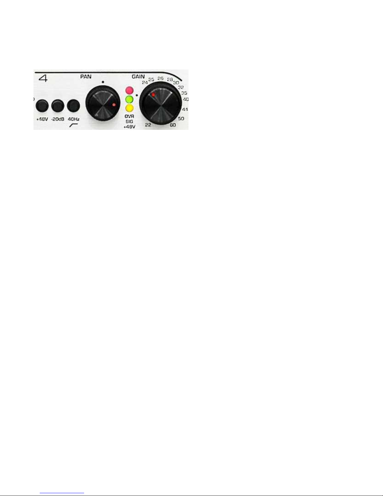
Each preamp channel includes switches for
phantom power, a 20 dB pad, and a 40 Hz
high-pass filter. Each channel also has a
center-detent MirrorPan™ control, a 41detent gain control, a Phantom warning LED,
and a 2-segment output level meter. Inputs
are fully protected against overloads and
phantom power transients.
Input Topology
The first gain stage on each microphone input
is built around precision-matched monolithic
low-noise transistor quads. Bandwidth is 500
kHz, IMD and THD are virtually non-existent.
The PRE420 is designed to achieve faithful
and transparent microphone amplification.
Microphone Gain Controls
These controls are a 41-detent pots that
accurately set the first-stage gain of each
preamplifier. These controls are calibrated for
precise minimum and maximum gain. This
calibration provides accurate channel-tochannel matching, and allows precise control
of stereo microphone pairs.
Maximum gain is calibrated for exactly 60 dB,
but may be adjusted to any value between 50
and 70 dB using the calibration procedure in
this manual. Minimum gain is 22 dB without
the pad, and 2 dB with the pad enabled.
TIP: ENGAGE THE PAD ON ANY UNUSED
INPUT AND TURN THE MICROPHONE
GAIN CONTROL TO MINIMUM TO REDUCE
NOISE AT THE MIXER OUTPUTS.
All signal paths in the PRE420 are
aggressively protected from RF and EMI
(electro-magnetic interference). For example,
the multi-layer printed circuit board uses a
special construction technique that creates a
3-dimensional shield surrounding each miclevel signal-trace to block RF interference.
Star-quad trace layouts prevent magnetic
interference. Benchmark's innovative
shielding and filtering techniques have given
Benchmark mic-preamps a proven track
record for exceptional performance even in
the most difficult environments.
Common mode signals in the audio band are
removed with a precisely trimmed differential
amplifier. The PRE420 even includes a
subsonic common-mode trim adjustment on
each microphone input that eliminates
sensitivity to +48V ripple caused by power
supply noise and/or the loading of
microphone electronics.
Phantom Power Switches
• In = Phantom On
• Out = Phantom Off
Each channel has a +48V warning LED that
will illuminate when +48V is present on the
microphone inputs.
CAUTION: ALWAYS TURN OFF PHANTOM
POWER AND WAIT FOR THE +48V LED TO
GO OUT BEFORE CONNECTING OR
DISCONNECTING MICROPHONES.
Input Protection
Under certain circumstances, phantom power
can cause large voltage transients. The
PRE420 is equipped with high-speed high-
PRE420 Instruction Manual – rev. E Page 9
Page 10

current low-capacitance input protection
circuits that protect the sensitive low-noise
input transistors from the worst-case
phantom-induced transients.
Large transients are produced when a
microphone is connected or disconnected
while phantom power is on. The worst
possible transients occur when a microphone
cable has an intermittent short to ground
from either pin 2 or pin 3. The PRE420 is
very well protected against both of the above.
For the protection of your microphones (and
your ears), we strongly recommend shutting
off phantom power several seconds before
connecting or disconnecting a microphone.
PRE420 Instruction Manual – rev. E Page 10
Page 11

MirrorPan™ Pan Controls
The PRE420 incorporates Benchmark’s new
MirrorPan™ constant-power pan control. The
advantages of MirrorPan™ include:
• Accurate 3-dB constant-power pan law
• Accurate balance at center detent
• Excellent channel separation when fully
panned
• Ultra-low distortion
• Ultra-low noise
Benchmark’s MirrorPan circuit eliminates the
distortion and pan-law errors caused by panpot wiper current. The center detent is
precisely calibrated for an accurate center
pan, and channel separation is excellent when
fully panned.
20 dB Pads
• In = Pad Enabled
• Out = Pad Off
The 20dB pad applies a 150-Ohm resistor
across the inputs of the preamplifier.
Engaging the pad on an unused input
terminates the preamplifier with
approximately the same resistance as a
typical microphone, and drops the EIN of the
preamplifier to its specified value. If a
microphone is not connected, engage the pad
to terminate the input.
TIP: ENGAGE THE PAD ON ANY UNUSED
INPUT AND TURN THE MICROPHONE
GAIN CONTROL TO MINIMUM TO REDUCE
NOISE AT THE MIXER OUTPUTS.
40 Hz High-Pass Filters
• In = Filter Enabled
• Out = Filter Off
The 40 Hz high-pass filter is a second-order
filter with a slope of 12 dB per octave. This
filter is intended to remove unwanted
subsonic noise and rumble caused by sources
such as HVAC, air currents, and vibration.
The 20 dB Pad allows the connection of line
level signals as high as 27 dBu. Without the
pad, the maximum input level is 7 dBu. The
input impedance of the PRE420 is 1.37k
Ohms with the pad enabled and 8.13k Ohms
when the pad is off. The pad is constructed
from two 750 Ohm series resistors plus one
150 Ohm shunt resistor.
Terminating Unused Inputs
The pad should be used to apply a 150 Ohm
termination to an unused microphone input.
Microphone preamplifiers will amplify the
Johnson noise from the source resistance
connected to the input. Most microphones
have a source resistance of about 150 Ohms.
But, an un-terminated preamplifier sees only
its own input impedance. The input
impedance of the PRE420 is 8.13k Ohms.
The Johnson noise of a 150-Ohm resistor is
-130.8 dBu while the Johnson noise from an
8.13k-Ohm resistor is -113.5 dBu. An unterminated microphone input will be about 17
dB noisier than an input that is properly
terminated.
LED Meters ---- Direct Outputs
Each preamp channel has a direct output.
Each direct output is equipped with a twosegment LED meter.
The green LED shows signal presence. The
intensity of the green LED varies with signal
level over a range of -8 dBu to +24 dBu. The
green LED reaches half brightness at an
output level of about +4 dBu, and is near full
brightness at +24 dBu.
The red LED is factory preset to illuminate at
an output level of precisely +24 dBu, but may
be adjusted to other levels between 20 dBu
and 29 dBu. The red LED is driven by a peak
detection and stretching circuit so that very
short transients can be observed.
The red LED is a warning indicator not a clip
indicator. The direct outputs have 5.5 dB of
remaining headroom when the red LED is just
illuminated. The mix amps have a minimum
of 2 dB of headroom when all channels are
just illuminating the red LEDs.
PRE420 Instruction Manual – rev. E Page 11
Page 12
Solo Bus
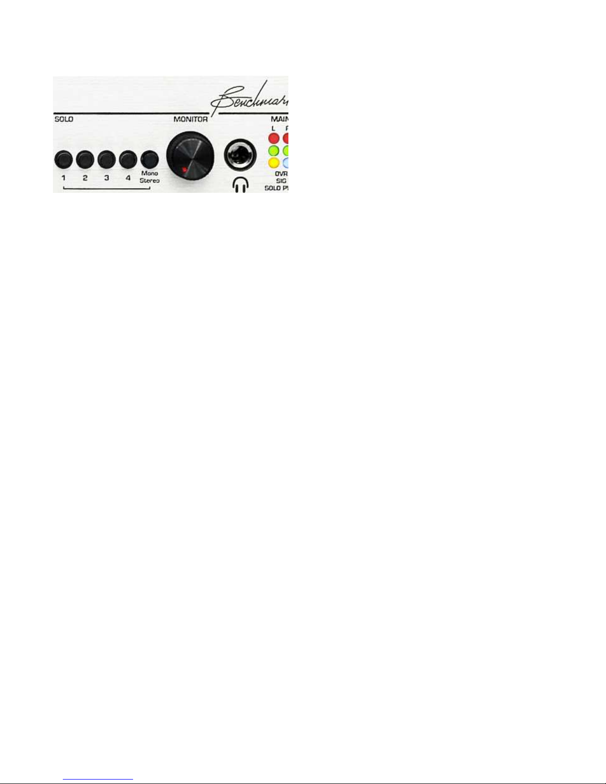
The PRE420 has a flexible solo bus that
allows:
• Mono monitoring of any mix of
microphones
• Stereo (post pan) monitoring of any
combination of microphones
• Stereo monitoring of the main mix bus
• Mono monitoring of the main mix bus
The output of the solo bus is directed to the
“monitor” fader and then to the headphone
and “control room” outputs.
Stereo/Mono Solo Switch
Microphones may be monitored before the
pan control (mono) or after the pan control
(stereo). Press the “Mono/Stereo” switch for
stereo solo. Stereo monitoring can be used
to check the pan position of a single
microphone or any combination of
microphones.
If none of the 4 microphone solo buttons are
pressed, the main stereo mix is directed to
the solo bus.
NOTE: The “Mono/Stereo” switch is only
functional when one or more microphone solo
buttons are pressed. This makes it easy to
toggle between the main stereo mix and a
mono solo of a single microphone.
TIP: TO CHECK A MIX FOR MONOCOMPATIBILITY, PRESS ALL 4
MICROPHONE SOLO BUTTONS. THEN,
USE THE “MONO/STEREO” BUTTON TO
TOGGLE BETWEEN THE MONO MIX AND
THE MAIN STEREO MIX.
Solo Switches
The solo bus has one solo button for each of
the 4 channels. These can be pressed in any
combination to create a mix of microphones.
If any microphone solo button is pressed, the
“Solo” indicator will illuminate.
PRE420 Instruction Manual – rev. E Page 12
Page 13

Control Room
Monitor Fader
Outputs
The output of the solo bus is directed to the
“monitor” fader and then to the headphone
and “control room” outputs.
Maximum output level is 29.5 dBu. All drivers
are high-current low-distortion amplifiers.
These are capable of driving loads as low as
300 Ohms without an increase in distortion.
Control Room Mute Switch
TIP: THE “CONTROL ROOM” OUTPUTS
CAN BE SET TO AUTOMATICALLY MUTE
WHENEVER A HEADPHONE IS INSERTED.
PRESS THE REAR-PANEL BUTTON TO
ENABLE THE AUTO-MUTE FUNCTION.
Driving Unbalanced Loads
CAUTION: ALWAYS LEAVE XLR PIN 3
FLOATING WHEN DRIVING UNBALANCED
LOADS.
The “monitor” fader is located to the right of
the solo buttons. It controls the output level
of the headphone jack and the balanced
control room outputs.
This stereo fader has factory-adjusted
balance trim circuitry to provide accurate L/R
balance.
XLR to RCA Wiring:
1. Connect XLR pin 2 (+) to RCA center pin.
2. Connect XLR pin 1 (GND) to RCA shield.
3. Make no connection to XLR pin 3 (-).
XLR to ¼” TS Wiring:
1. Connect XLR pin 2 (+) to Tip.
2. Connect XLR pin 1 (GND) to Sleeve.
3. Make no connection to XLR pin 3 (-).
PRE420 Instruction Manual – rev. E Page 13
Page 14

HPA2™ Headphone
Output
The output of the solo bus is directed to the
“monitor” fader and then to the headphone
and “control room” outputs.
The headphone output is driven by
Benchmark’s signature HPA2™ headphone
amplifier. This high-current, high-output
amplifier has an output impedance of 0Ohms. It is designed to drive loads as low as
30-Ohms without any increase in distortion.
It also has sufficient amplitude to drive lowsensitivity 600-Ohm headphones.
The HPA2™ includes current-limiting circuits
that fully protect against damage from short
circuits. This is important because the right
channel of a headphone amplifier will
experience a short whenever a mono phone
plug is inserted into the stereo headphone
jack. Shorts may also occur when a plug is
partially inserted.
impedance decreases. This distortion can be
eliminated with a properly designed 0-Ohm
headphone amplifier.
The performance of the HPA2™ does not
change when headphones are driven. THD+N
measurements for no-load, 30-Ohm resistive
load, and 30-Ohm headphone load, and 600Ohm headphone load are virtually identical.
The HPA2™ will substantially improve the
sound of 30 and 60-Ohm headphones. It will
make very noticeable improvements with
600-Ohm headphones.
‘‘0-Ohm’’ Output Impedance
Most headphone amplifiers use series
resistors to maintain stability and protect
against short-circuit conditions. These
resistors are usually at least 30-Ohms, and
have a negative impact on performance. A
headphone amplifier with series resistors may
measure very well when driving resistive
loads. However, the same amplifier will
measure very poorly when driving a
headphone load. Unfortunately most
manufacturers do not specify headphone
amplifier performance with anything other
than ideal resistive loads. Our measurements
show that headphones do not behave like
resistive loads.
Headphone Performance
In our tests we have measured substantial
distortion across resistors that are wired in
series with headphones. We conducted
measurements with a variety of headphones.
In general, distortion increases as headphone
PRE420 Instruction Manual – rev. E Page 14
Page 15
Mix Outputs
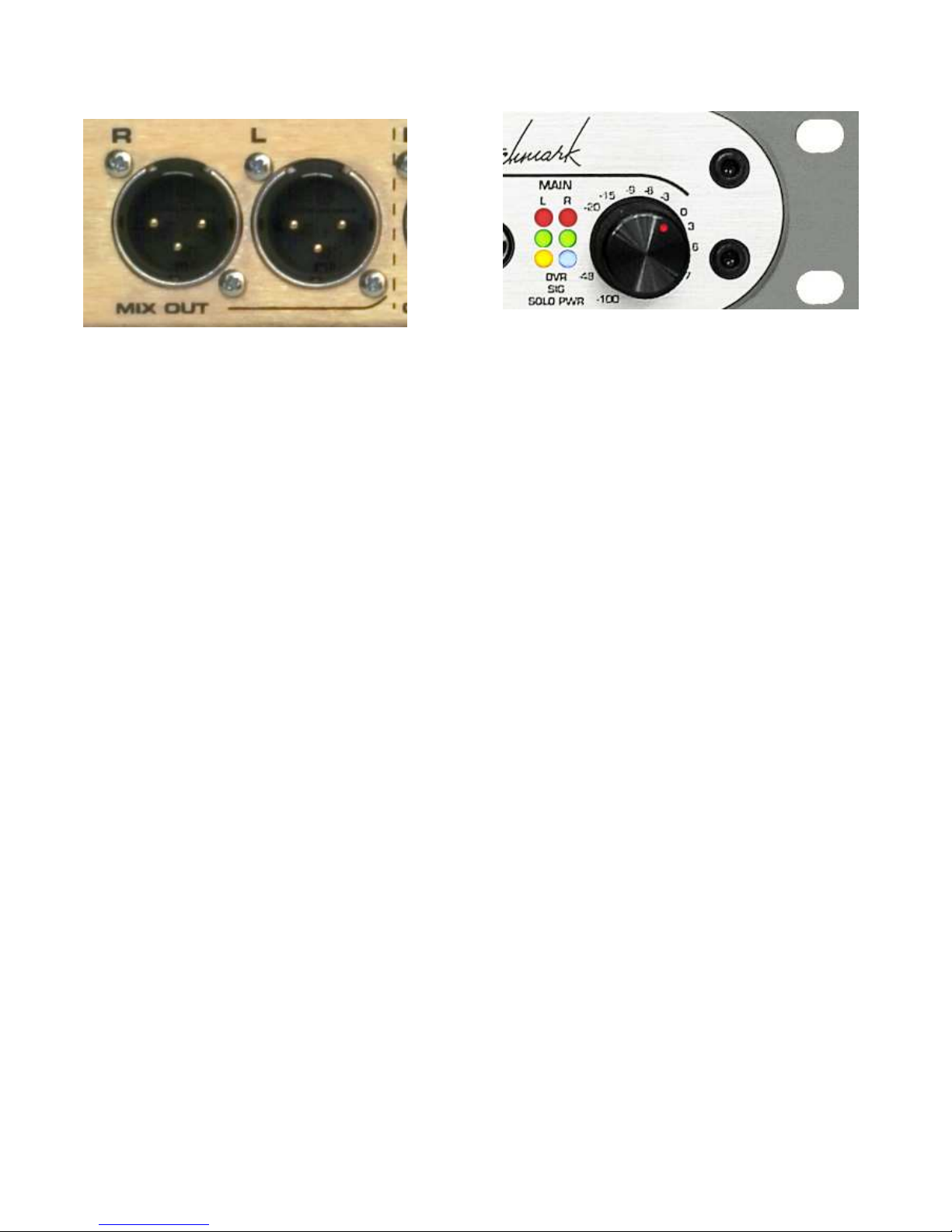
The output of the mix bus is directed to the
“Main” fader and then to the “Main” outputs.
Maximum output level is 29.5 dBu. All drivers
are high-current low-distortion amplifiers.
These are capable of driving loads as low as
300 Ohms without an increase in distortion.
TIP: ENGAGE THE PAD ON ANY UNUSED
INPUT AND TURN THE MICROPHONE
GAIN CONTROL TO MINIMUM TO REDUCE
NOISE AT THE MIXER OUTPUTS.
Driving Unbalanced Loads
CAUTION: ALWAYS LEAVE XLR PIN 3
FLOATING WHEN DRIVING UNBALANCED
LOADS.
XLR to RCA Wiring:
1. Connect XLR pin 2 (+) to RCA center pin.
2. Connect XLR pin 1 (GND) to RCA shield.
3. Make no connection to XLR pin 3 (-).
XLR to ¼” TS Wiring:
1. Connect XLR pin 2 (+) to Tip.
2. Connect XLR pin 1 (GND) to Sleeve.
3. Make no connection to XLR pin 3 (-).
Main Fader
The “main” fader is located at the far right of
the front panel. This stereo fader has factory
adjusted balance trim circuitry to provide
accurate L/R balance.
LED Meters ---- Mix Outputs
The left and right mix outputs are equipped
with two-segment LED meters located to the
left of the main fader.
The green LED shows signal presence. The
intensity of the green LED varies with signal
level over a range of -8 dBu to +24 dBu. The
green LED reaches half brightness at an
output level of about +4 dBu, and is near full
brightness at +24 dBu.
The red LED is factory preset to illuminate at
an output level of precisely +24 dBu, but may
be adjusted to other levels between 20 dBu
and 29 dBu. The red LED is driven by a peak
detection and stretching circuit so that very
short transients can be observed.
The red LED is a warning indicator not a clip
indicator. The direct outputs have 5.5 dB of
remaining headroom when the red LED is just
illuminated.
.
PRE420 Instruction Manual – rev. E Page 15
Page 16

Rack Mounting
To enable rack mounting, the front panel of
the PRE420 has rack-mount holes that are
machined to conform to standard rack mount
dimensions. The PRE420 ships with rubber
feet that should be removed whenever
another device will be mounted directly below
the PRE420.
Mounting Near Other
Equipment
CAUTION: STRAY MAGNETIC FIELDS
FROM ADJACENT EQUIPMENT MAY
CAUSE MAGNETICALLY INDUCED HUM IN
THE SENSITIVE HIGH-GAIN PREAMP
CIRCUITS.
The PRE420 may be mounted directly above
or below other PRE420 preamps. It may also
be mounted directly above or below
Benchmark DAC1 and ADC1 converters. The
Pre420 is well shielded but we cannot
guarantee that unknown pieces of equipment
will not cause interference if mounted too
close to the PRE420. Follow the procedure
below when mounting near other equipment:
TIP: TO CHECK FOR MAGNETIC
INTERFERENCE FROM ADJACENT
EQUIPMENT:
• Disconnect all microphones
• Turn on all pads (to back-terminate
microphone inputs)
• Set all preamp gain controls at maximum
• Listen to headphone output
• Unplug adjacent equipment to determine
if there is any magnetic interference
TIP: IN MANY CASES, POWER SWITCHES
DO NOT TURN OFF ALL OF THE
MAGNETIC COMPONENTS IN AN
ELECTRONIC DEVICE. THEREFORE, WHEN
PERFORMING MAGNETIC INTERFERENCE
TESTS, IT IS IMPORTANT TO UNPLUG
THE ADJACENT EQUIPMENT TO INSURE
THAT THESE DEVICES ARE TRULY OFF.
PRE420 Instruction Manual – rev. E Page 16
Page 17
Performance Graphs
Audio Precision
Frequency Response
+3
+2.8
+2.6
+2.4
+2.2
+2
+1.8
+1.6
+1.4
+1.2
+1
+0.8
+0.6
+0.4
d
+0.2
B
+0
r
-0.2
A
-0.4
-0.6
-0.8
-1
-1.2
-1.4
-1.6
-1.8
-2
-2.2
-2.4
-2.6
-2.8
-3
10 200k20 50 100 200 500 1k 2k 5k 10k 20k 50k 100k
02/19/07 11:33:00PRE420 - Frequency Response
Hz
ColorSweep Trace Line Style Th ick Data Axis Comm ent
1 1 Red Solid 4 Anlr.Level A Left HP Filter Off
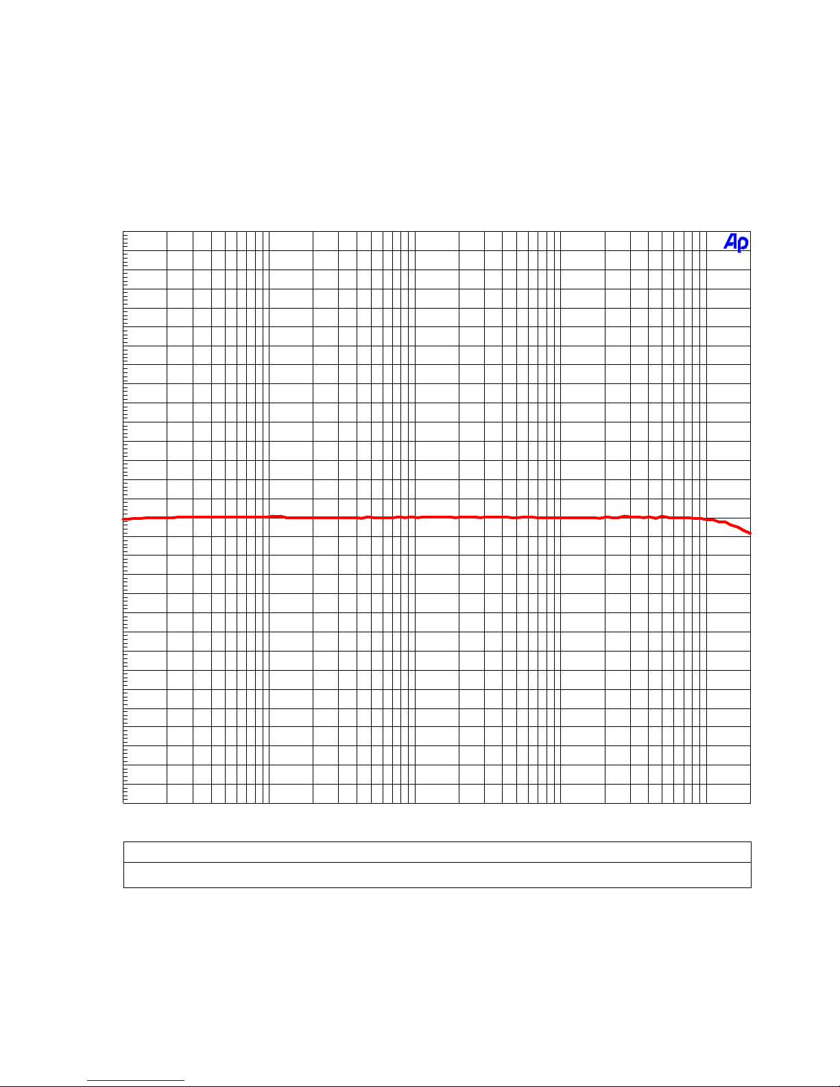
The above graph shows the frequency response of the PRE420 with the 40 Hz high-pass filter off.
The amplitude response measures -0.020 dB at 10 Hz and -0.165 dB at 200 kHz. The bass
response extends well below the 10-Hz limitation of the test equipment, and the high-frequency
response extends well above the 200 kHz limit of the test equipment.
PRE420 Instruction Manual – rev. E Page 17
Page 18
Audio Precision
High-Pass Filter - Frequency Response
+3
+2.8
+2.6
+2.4
+2.2
+2
+1.8
+1.6
+1.4
+1.2
+1
+0.8
+0.6
+0.4
d
+0.2
B
+0
r
-0.2
A
-0.4
-0.6
-0.8
-1
-1.2
-1.4
-1.6
-1.8
-2
-2.2
-2.4
-2.6
-2.8
-3
10 200k20 50 100 200 500 1k 2k 5k 10k 20k 50k 100k
Hz
02/19/07 11:33:00PRE420 - Frequency Response
ColorSweep Trace Line Style Th ick Data Axis Comm ent
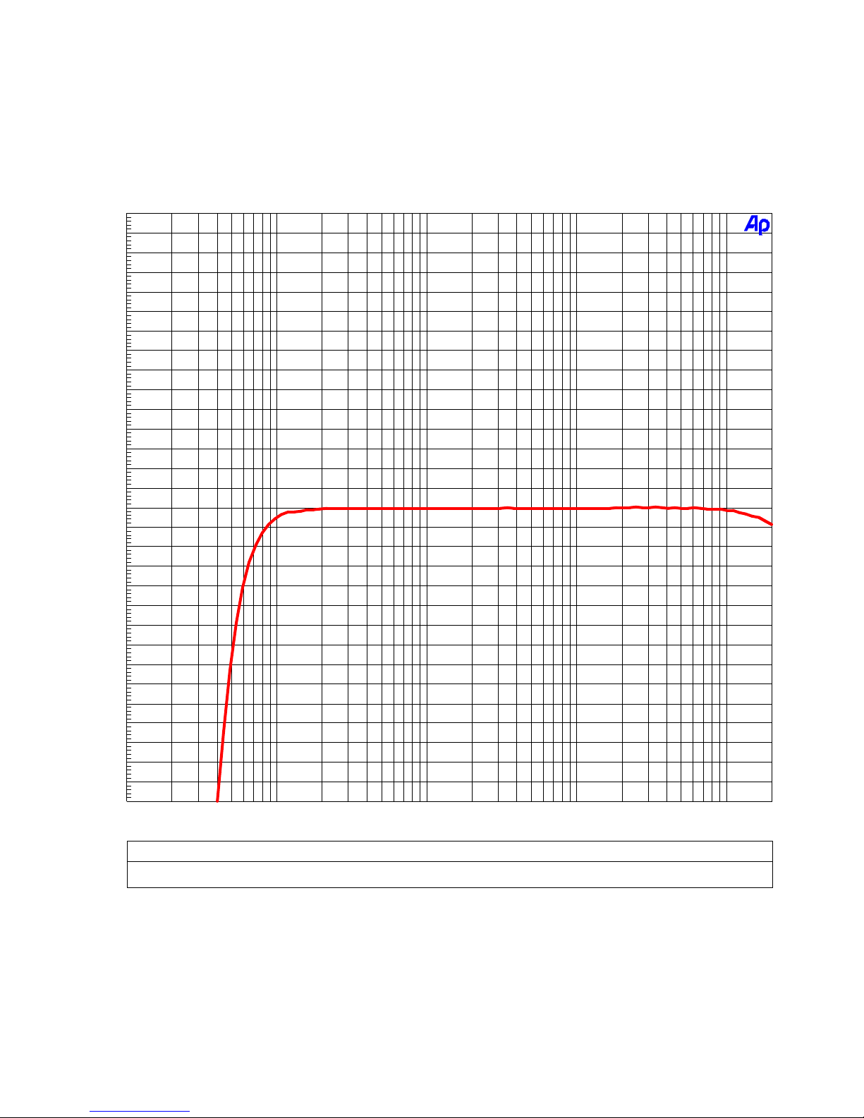
2 1 Red Solid 4 Anlr.Level A Left HP Filter On
The above graph shows the response of the 40 Hz high-pass filter. Response is -3 dB at 40 Hz with
a slope of 12 dB/octave.
PRE420 Instruction Manual – rev. E Page 18
Page 19
Inter-Channel Phase Response
Audio Precision
+1
+0.9
+0.8
+0.7
+0.6
+0.5
+0.4
+0.3
+0.2
+0.1
d
+0
e
g
-0.1
02/19/07 11:35:37PRE420 - Inter-Channel Phase Response
-0.2
-0.3
-0.4
-0.5
-0.6
-0.7
-0.8
-0.9
-1
10 100k20 50 100 200 500 1k 2k 5k 10k 20k 50k
Hz
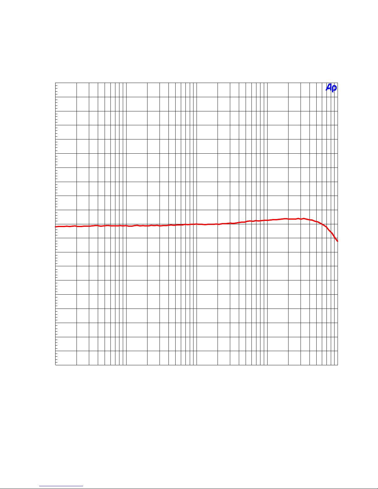
This graph shows that the differential phase is significantly better than ± 0.05 degrees from 10 Hz
to 20 kHz.
PRE420 Instruction Manual – rev. E Page 19
Page 20
THD+N vs. Frequency
Audio Precision
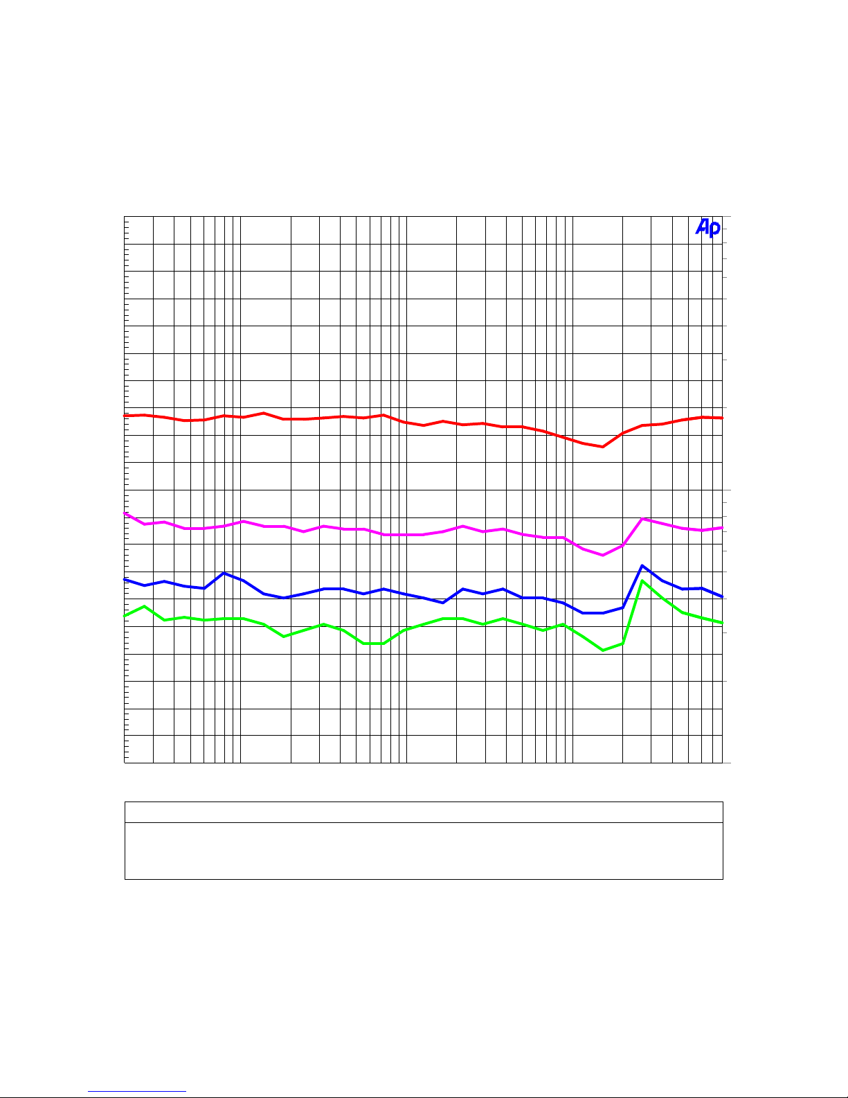
Measurement Bandwidth = 10Hz to 80 kHz, Gain = 30 to 60 dB, Output Level = +4 dBu
02/21/07 09:56:41PRE420 - THD+N vs Frequency at 60 dB Gain, BW=80 kHz
-80
-82
-84
-86
-88
-90
-92
-94
-96
-98
d
-100
B
-102
-104
-106
-108
0.01
0.005
0.002
0.001
0.0005
%
-110
-112
-114
-116
-118
-120
20 80k50 100 200 500 1k 2k 5k 10k 20k 50k
Hz
ColorSweep Trace Li ne Style Thick Data Axis Comm ent
1 1 Red Solid 4 Anl r.THD+N Ratio Left 60 dB Gain (top trace)
2 1 Magenta Soli d 4 Anlr.THD+N Ra tio Left 5 0 dB Gain
3 1 Blue Soli d 4 Anlr.THD+N Ra tio Left 40 dB Gain
4 1 Green Solid 4 Anlr.THD+N Ratio Left 30 dB Gain (bottom trace)
This graph shows that THD+N does not rise with frequency – even at maximum gain.
0.0002
0.0001
PRE420 Instruction Manual – rev. E Page 20
Page 21
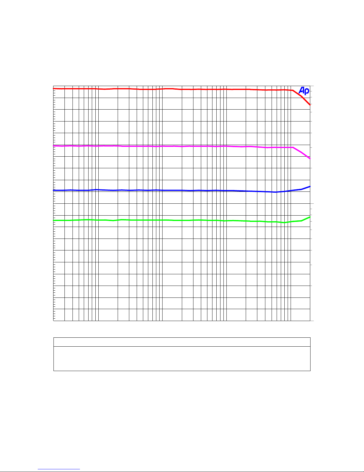
Wideband THD+N vs. Frequency
Audio Precision
Measurement Bandwidth = 10 Hz to 500 kHz, Gain = 30 to 60 dB, Output Level = +4 dBu
02/19/07 16:16:11PRE420 - Wideband THD+N vs Frequency, BW=500 kHz
-60
-62
-64
-66
-68
-70
-72
-74
-76
-78
d
-80
B
-82
-84
-86
-88
0.1
0.05
0.02
0.01
0.005
%
-90
-92
-94
-96
-98
-100
20 200k50 100 200 500 1k 2k 5k 10k 20k 50k 100k
Hz
ColorSweep Trace Li ne Style Thick Data Axis Comm ent
1 1 Red Solid 4 Anl r.THD+N Ratio Left 60 dB Gain (top trace)
2 1 Magenta Soli d 4 Anlr.THD+N Ra tio Left 5 0 dB Gain
3 1 Blue Soli d 4 Anlr.THD+N Ra tio Left 40 dB Gain
4 1 Green Solid 4 Anlr.THD+N Ratio Left 30 dB Gain (bottom trace)
0.002
0.001
This graph shows that THD+N does not rise above noise – even at very high frequencies. The 500
kHz measurement bandwidth elevates the noise by 28 dB relative to a 20 kHz measurement
bandwidth.
PRE420 Instruction Manual – rev. E Page 21
Page 22
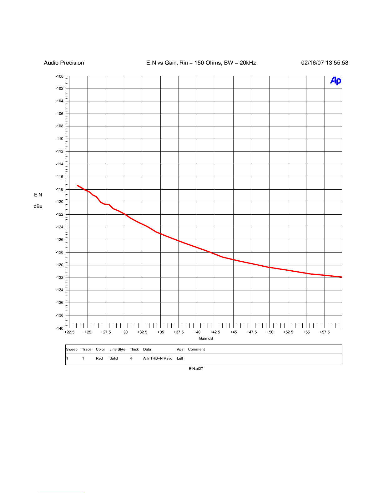
Equivalent Input Noise vs. Gain
The above plot shows the Equivalent Input Noise (EIN) of the PRE420 as a function of gain.
Measurement bandwidth is 20 Hz to 20 kHz. Input termination is 150 Ohms.
PRE420 Instruction Manual – rev. E Page 22
Page 23
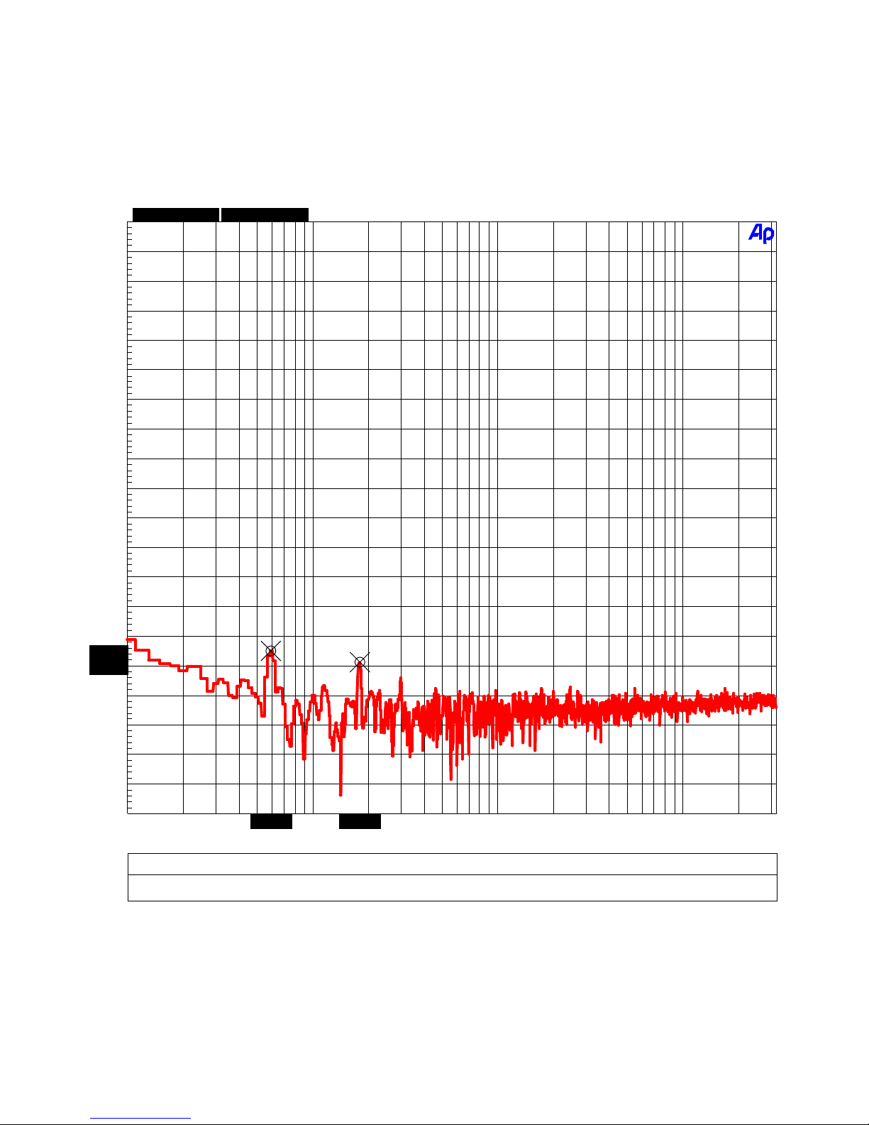
Noise Spectrum
Audio Precision
dx=120.996 Hz
dy=-3.948 dB
32k B-H FFT, Gain = 60 dB, 0 dBr = 0 dBu at input
+0
-10
-20
-30
-40
-50
-60
-70
-80
-90
d
B
-100
r
A
-110
02/19/07 11:27:19Noise Spectrum, Gain = 60 dB, 0 dBr = 0 dBu at Input
-120
-130
-140
-145.066
-150
-149.014
-160
-170
-180
-190
-200
10 30k20 50 100 200 500 1k 2k 5k 10k 20k
ColorSweep Trace Line Style Thick Data Axis C omm ent Cu rsor1 Curs or2
1 1 Red Solid 4 Fft.C h.1 Ampl L eft *-145 .066 dBr A * -149.014 dBr A
59.6606 180.657
Hz
The above graph demonstrates that the PRE420 is free of hum and noise. The highest tone is 60Hz line-related hum and is at a level equivalent to an input level of -145 dBu. 180-Hz hum is at an
equivalent input level of -149 dBu.
PRE420 Instruction Manual – rev. E Page 23
Page 24
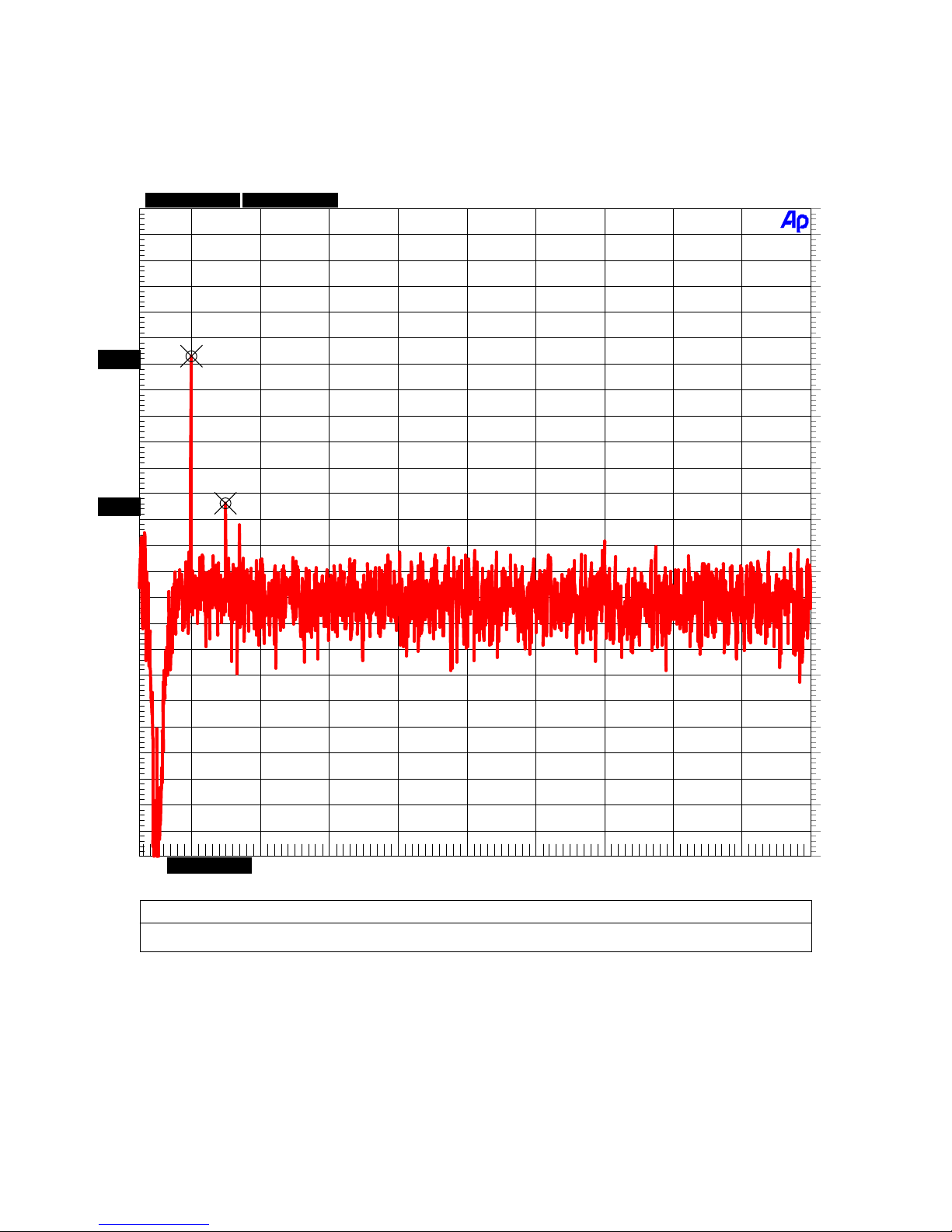
THD Spectrum at 1 KHz
Audio Precision
dx=1.00024 kHz
dy=-11.343 dB
02/21/07 09:43:491 kHz FFT at 60 dB Gain, Output Level = +24 dBu, 0 dBr = +24 dBu
-111.404
-122.747
d
B
r
A
-100
-102
-104
-106
-108
-110
-112
-114
-116
-118
-120
-122
-124
-126
-128
-130
-132
-134
-100
-102
-104
-106
-108
-110
-112
-114
-116
-118
-120
-122
-124
-126
-128
-130
-132
-134
d
B
r
A
-136
-138
-140
-142
-144
-146
-148
-150
2.00513k3.00537k
2k 20k4k 6k 8k 10k 12k 14k 16k 18k
Hz
ColorSweep Trace Line Style Thick Data Axis C omm ent Cu rsor1 Curs or2
1 1 Red Solid 4 Fft.C h.2 Ampl L eft *-111 .404 dBr A * -122.747 dBr A
-136
-138
-140
-142
-144
-146
-148
-150
The above FFT plot shows that the PRE420 has very little harmonic distortion. The 1 kHz test tone
is notched out with a THD analyzer to improve the resolution of the test. Distortion is exceptionally
low. 2
nd
-harmonic distortion measures better than -111 dB. 3rd-harmonic distortion measures
better than -122 dB. Note the absence of higher-order harmonics.
PRE420 Instruction Manual – rev. E Page 24
Page 25

THD Spectrum at 10 KHz
Audio Precision
dx=10.0073 kHz
dy=-9.515 dB
-100
-102
-104
-106
-108
-109.271
-110
-112
-114
-116
-118
-118.787
-120
-122
d
-124
B
r
-126
A
-128
-130
-132
-134
02/19/07 11:09:3010 kHz FFT at 60 dB Gain, Output Level = +24 dBu, 0 dBr = +24 dBu
-136
-138
-140
-142
-144
-146
-148
-150
2k 32k4k 6k 8k 10k 12k 14k 16k 18k 20k 22k 24k 26k 28k 30k
Hz
ColorSweep Trace Line Style Thick Data Axis C omm ent Cu rsor1 Curs or2
1 1 Red Solid 4 Fft.C h.2 Ampl L eft *-109 .271 dBr A * -118.787 dBr A
20.022k 30.0293k
The above FFT plot shows that the PRE420 has very little harmonic distortion at high frequencies.
The 10 kHz test tone is notched out with a THD analyzer to improve the resolution of the test. The
20-kHz 2
nd
-harmonic distortion measures better than -109 dB. The 30-kHz 3rd-harmonic distortion
measures better than -118 dB.
PRE420 Instruction Manual – rev. E Page 25
Page 26

Specifications
Microphone Preamps
Number of Preamps 4
Connectors Gold-Pin Neutrik™ female XLR with
direct ground feature
Grounding Direct bonding of pin 1 to chassis
Input Impedance (pad off) 8.1k Ohms
Input Impedance (pad on) 1.37k Ohms
Gain Range (with pad off) 22 dB to 60 dB (to direct outputs)
Gain Range (with pad on) 2 dB to 40 dB (to direct outputs)
Maximum Input Level (pad off) +7 dBu (+4.8 dBV, 1.7 Vrms)
Maximum Input Level (pad on) +27 dBu (+24.8 dBV, 17.4 Vrms)
Phantom Power +48V w/individual switches
High-Pass (rumble filter) 40 Hz second-order 12-dB/octave
Preamp Bandwidth -0.02 dB at 10 Hz
-0.17 dB at 200 kHz
- 3 dB at 500 kHz
EIN at 60 dB Gain (20 Hz to 20 kHz) – to any output -128 dBu at 150 Ohms
-131 dBu at 40 Ohms
-133 dBu at 0 Ohms
THD+N (1 kHz, BW=20 kHz, to any output at +27 dBu) -112 dB, 0.00024% at 22 dB Gain
-110 dB, 0.0003% at 35 dB Gain
-108 dB, 0.00038% at 40 dB Gain
-101 dB, 0.00085% at 55 dB Gain
IMD (50Hz and 7 kHz, to any output at +24 dBu) -104 dB, 0.0006% at 35 dB Gain
-104 dB, 0.0006% at 40 dB Gain
PRE420 Instruction Manual – rev. E Page 26
Page 27

Direct Outputs
Number of Outputs 4
Connectors Gold-Pin Neutrik™ male XLR with
direct ground feature
Output Impedance 60 Ohms Balanced
30 Ohms Unbalanced (pin 3 floating)
Maximum Output Level without clipping +29.5 dBu
Drive capability at rated THD+N 300 Ohms
Output Type Transformerless
Voltage and Impedance Balanced
Control Room and Main Outputs
Number of Outputs 4, (2 control room + 2 main)
Connectors Gold-Pin Neutrik™ male XLR with
direct ground feature
Output Impedance 60 Ohms Balanced
30 Ohms Unbalanced (pin 3 floating)
Maximum Output Level without clipping +29.5 dBu
Monitor Gain Control L/R Balance +/- 0.01 dB at full clockwise rotation
+/- 0.3 db at middle of rotation
Drive capability at rated THD+N 300 Ohms
Output Type Transformerless
Voltage and Impedance Balanced
PRE420 Instruction Manual – rev. E Page 27
Page 28

MirrorPan™ Constant-Power Pan Circuit
Number of pan controls 4
Pan Law 3-dB (constant power to stereo out)
Deviation from Constant Power +/- 0.25 dB
Channel Separation when Fully Panned > 71 dB
Balance at Center Detent +/- 0.25 dB
THD+N Better than -112 dB, 0.00024%
HPA2™ Headphone Amplifier
Number of Outputs 1
Connector ¼” TRS with switch contacts
Output Impedance < 0.11 Ohms, 10 Hz to 200 kHz
Maximum Output Level at 0.001% THD+N +23.5 dBu into 600 Ohms (0.24 W)
+19.5 dBu into 30 Ohms (1.78 W)
Maximum Output Current 250 mA
Drive capability at rated THD+N 30 Ohms
Overload Protection (independent per channel) Current limited at 300 mA
Thermal Shutdown
Bandwidth > 500 kHz
-0.014 dB at 10 Hz
-0.013 dB at 200 kHz
THD+N -106 dB, 0.0005% into 30 Ohms at
+18dBu (1.26 W)
PRE420 Instruction Manual – rev. E Page 28
Page 29

LED Status Indicators and Meters
+48V Phantom Indicators 4
Solo Warning Indicator 1
Power Indicator 1 Blue
Meter Indicators 6 Dual LED Meters
Meter Locations 4 – microphone inputs
2 – main outputs
Meter Specifications Green LED – intensity modulated
signal presence, threshold = -8 dBu,
full brightness at +24 dBu
Red LED – threshold = +24 dBu
adjustable, includes peak-responding
pulse stretch circuit for viewing fast
transients
AC Power Requirements
Input Operating Voltage Range (VAC RMS) 120 V setting: 105 V min, 140 V max
220 V setting : 200 V min, 285 V max
Frequency 50-60 Hz
Power 27 Watts Idle
27 Watts Typical Program
35 Watts Maximum
Fuses 5 x 20 mm (2 required)
0.5 A 250 V Slo-Blo®
Littelfuse® HXP218.500 or Equivalent
PRE420 Instruction Manual – rev. E Page 29
Page 30

Dimensions
Form Factor 19” Rack Mount, 1 RU High
Depth behind front panel 11.75” (298.5 mm)
Overall depth including knobs and connectors but without
power cord
Width excluding 19” rack ears 17.5” (445 mm)
Height excluding removable feet 1.725” (43.8 mm)
12.625” (321 mm)
Weight
PRE420 only 8.05 lb. (3.65 kg)
PRE420 with power cord, extra fuses, and manual 9 lb. (4.1 kg)
Shipping weight 11 lb. (5 kg)
PRE420 Instruction Manual – rev. E Page 30
Page 31

Regulatory Compliance
FCC Notice (U.S. Only)
NOTICE: This equipment has been tested and found to comply with the limits for a Class B
digital device, pursuant to Part 15 of the FCC Rules. These limits are designed to provide
FCC Notice
reasonable protection against harmful interference in a residential installation. This equipment
generates, uses, and can radiate radio frequency energy and, if not installed and used in
accordance with the instructions, may cause harmful interference to radio communications.
However, there is no guarantee that interference will not occur in a particular installation. If
this equipment does cause harmful interference to radio or television reception, which can be
determined by turning the equipment off and on, the user is encouraged to try to correct the
interference by one or more of the following measures:
• Reorient or relocate receiving antenna.
• Increase the separation between the equipment and receiver.
• Connect the equipment into an outlet on a circuit different from that to which the receiver is
connected.
• Consult the dealer or an experienced radio/TV technician for help.
This device complies with Part 15 of the FCC rules. Operation is subject to the following two
conditions:
1. This device may not cause harmful interference.
2. This device must accept any interference received including interference that may cause
undesired operation.
NOTICE: Changes or modifications not expressly approved by the party responsible for
compliance could void the user's authority to operate the equipment.
RoHS Compliant Information
This statement clarifies Benchmark Media Systems, Inc. product compliance with the EU’s
(European Union) directive 2002/95/EC, or, RoHS (Restrictions of Hazardous Substances).
As of July 01, 2006, All Benchmark Media Systems, Inc. products placed on the European Union
market are compliant (containing quantity limit weight less than or equal to 0.1% (1000 ppm)
of any homogeneous Lead (Pb), Mercury (Hg), Hexavalent Chromium (Cr VI), and flame
RoHS Compliant Information
retardant Polybrominated Biphenyls (PBB) or Polybrominated Diphenyl Ethers (PBDE)).
PRE420 Instruction Manual – rev. E Page 31
Page 32
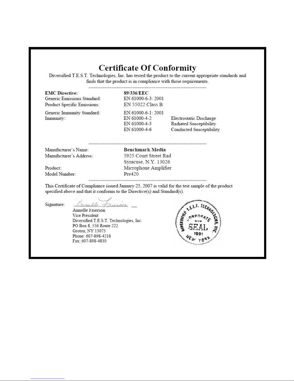
CE Certificate of Conformity
PRE420 Instruction Manual – rev. E Page 32
Page 33

Warranty Information
The Benchmark 1 Year Warranty
Benchmark Media Systems, Inc. warrants its products to be free from defects in material and
workmanship under normal use and service for a period of one (1) year from the date of
delivery.
This warranty extends only to the original purchaser. This warranty does not apply to fuses,
lamps, batteries, or any products or parts that have been subjected to misuse, neglect,
accident, modification, or abnormal operating conditions.
In the event of failure of a product under this warranty, Benchmark Media Systems, Inc. will
repair, at no charge, the product returned to its factory. Benchmark Media Systems, Inc. may,
at its option, replace the product in lieu of repair. If the failure has been caused by misuse,
neglect, accident, or, abnormal operating conditions, repairs will be billed at the normal shop
rate. In such cases, an estimate will be submitting before work is started, if requested by the
customer.
Attempts to deliberately deface, mutilate, or remove the product's label will render this
warranty void. Any PRE420 returned from the European Union for warranty repair must have
the required RoHS logo on the product label; otherwise, repairs will be billed at the normal
shop rate. Benchmark will not honor warranties for any products disingenuously purchased on
the US or Canadian markets for sale outside the US or Canada.
The foregoing warranty is in lieu of all other warranties, expressed or implied, including but not
limited to any implied warranty of merchantability, fitness or adequacy for any particular
purpose or use. Benchmark Media Systems, Inc. shall not be liable for any special, incidental,
or consequential damages, and reserves the right to charge this information without notice.
This limited warranty gives the consumer-owner specific legal rights, and there may also be
other rights that vary form state to state.
Notes on Warranty Repairs
An RMA (return merchandise authorization) number, issued by our Customer Service
Department, is required when sending products for repair.
They must be shipped to Benchmark Media Systems prepaid and preferably in their original
shipping carton with the RMA number clearly visible on the exterior of the packaging. A letter
should be included giving full details of the difficulty.
PRE420 Instruction Manual – rev. E Page 33
Page 34

Benchmark Extended Warranty
The Benchmark Extended 5* Year Warranty
Benchmark Media Systems, Inc. optionally extends the standard one (1) year warranty to a
period of five (5)* years from the date of delivery.
*For the extended warranty to become effective, the original purchaser must register the
product at the time of purchase either by way of the prepaid registration card or through the
product registration section of the Benchmark Media Systems, Inc. website. This optional
warranty applies only to products purchased within the US and Canada and is extended only to
the original purchaser.
Attempts to deliberately deface, mutilate, or remove the product's label will render this
warranty void. Benchmark will not honor warranties for any products disingenuously purchased
on the US or Canadian markets for export. The terms of the extended warranty are subject to
change without notice. For products purchased outside the US and Canada, please refer to the
Extended Two (2)** Year International Warranty.
The Benchmark’s Extended 2** Year International Warranty
Benchmark Media Systems, Inc. optionally extends the standard one (1) year warranty to a
period of two (2)** years from the date of delivery.
**For the extended warranty to become effective, the original purchaser must register the
product at the time of purchase either by way of the prepaid registration card or through the
product registration section of the Benchmark Media Systems, Inc. website. This optional
warranty applies only to products purchased outside the US and Canada and is extended only
to the original purchaser.
Attempts to deliberately deface, mutilate, or remove the product's label will render this
warranty void. Benchmark will not honor warranties for any products disingenuously purchased
on the US or Canadian markets for export. The terms of the extended warranty are subject to
change without notice. For products purchased in within the US and Canada, please refer to the
Extended Five (5)* Year Warranty.
PRE420 Instruction Manual – rev. E Page 34
Page 35

Calibration
CAUTION: ROUTINE CALIBRATION
SHOULD NOT BE REQUIRED. THE
FOLLOWING PROCEDURE SHOULD ONLY
BE USED BY A QUALIFIED TECHNICIAN.
This procedure will restore the PRE420 to
factory calibration if controls have been
moved from factory settings.
Required Equipment
Calibration requires an audio generator, an
audio level meter, and a VOM (multimeter).
ALL ADJUSTMENTS SHOULD BE MADE BY
A QUALIFIED TECHNICIAN IN THE
ORDER LISTED BELOW:
1. Unless otherwise noted, set all
microphone “Gain” controls fully
clockwise, all “Pan” controls on center
detent, “Monitor” level fully clockwise,
and “Main” level fully clockwise.
+48V Adjustment
2. Using a DC voltmeter, measure the
voltage across D23 and adjust “+48V
Adjust” (R107) until the meter reads
48V.
7. Connect audio level meter to channel 1
direct output.
8. Adjust channel 1 “Max Gain Lim”
(R53) until output level is +24 dBu at
channel 1 direct output.
9. Adjust channel 1 “Meter Threshold”
(R13) so that CH1 red LED just turns
on. This sets the meter to the factory
default threshold of +24 dBu.
10. Repeat steps 6 - 9 for channels 2
through 4 to adjust “Max Gain Lim”
(R112, R170, and R253) and “Meter
Threshold” (R71, R131, and R203).
Monitor Gain Balance
11. Press “Solo 1” button. All other
buttons must be released. This feeds a
mono signal to the solo bus.
12. Microphone 1 “Gain” control must be
fully clockwise.
13. Set “Monitor” level control at
maximum gain (fully clockwise).
14. Set audio tone generator to 1 kHz with
an output level of -36 dBu (or level
used in step 3).
15. Connect tone generator to microphone
1 input.
Microphone Gain and Metering
3. Release all push buttons on front
panel.
4. Turn all microphone “Gain” controls
fully clockwise.
5. Set audio tone generator to 1 kHz with
an output level of -36 dBu if you wish
to set maximum gain to 60 dB (factory
default). Set generator to -46 dBu if
you wish to set maximum gain to 70
dB, or -26 dBu if you wish to set
maximum gain to 50 dB.
6. Connect tone generator to microphone
1 input.
PRE420 Instruction Manual – rev. E Page 35
16. Connect audio level meters to control
room L & R outputs.
17. Adjust “Monitor Gain Bal” (R284) until
the control room L & R outputs are
balanced.
Microphone Pan Balance
18. Release all push buttons on front
panel.
19. Set “Pan” controls on center detent.
20. Microphone “Gain” controls should be
fully clockwise.
Page 36

21. Set audio tone generator to 1 kHz with
an output level of -36 dBu (or level
used in step 3).
22. Connect tone generator to microphone
1 input.
23. Connect audio level meters to “Control
Room” L & R outputs.
24. Adjust Channel 1 “Pan Bal” (R27) until
the “Control Room” L & R outputs are
balanced.
25. Move generator to microphone 2 input
and adjust Channel 2 “Pan Bal” (R81).
Repeat for channels 3 and 4 (R142
and R219).
Main Gain Balance
26. Release all push buttons on front
panel.
27. Microphone 1 “Gain” control must be
fully clockwise.
35. Set audio tone generator to 1 kHz with
an output level of -36 dBu (or level
used in step 3).
36. Connect tone generator to microphone
1 input.
37. Connect audio level meters to “Main” L
& R outputs.
38. Adjust “Main” level control until output
levels are exactly +24 dBu.
39. Adjust “L Meter Threshold” (R296)
and “R Meter Threshold” (R304) until
the “Main” L & R red LEDs just turn on.
28. Set “Main” level control at maximum
gain (fully clockwise).
29. Set audio tone generator to 1 kHz with
an output level of -36 dBu (or level
used in step 3).
30. Connect tone generator to microphone
1 input.
31. Connect audio level meters to “Main” L
& R outputs.
32. Adjust “Main Gain Bal” (R338) until
the “Main” L & R outputs are balanced.
Peak LED Adjust ---- Main
Outputs
33. Release all push buttons on front
panel.
34. Microphone 1 “Gain” control must be
fully clockwise.
PRE420 Instruction Manual – rev. E Page 36
Page 37

Copyright © 2007 Benchmark Media
Systems, Inc.
All rights reserved.
Benchmark Media Systems, Inc.
203 Hampton Place, Ste. 2
Syracuse, NY 13206
USA
+1-315-437-6300, FAX +1-315-437-8119
www.benchmarkmedia.com
PRE420 Instruction Manual – rev. E Page 37
 Loading...