

Page 1
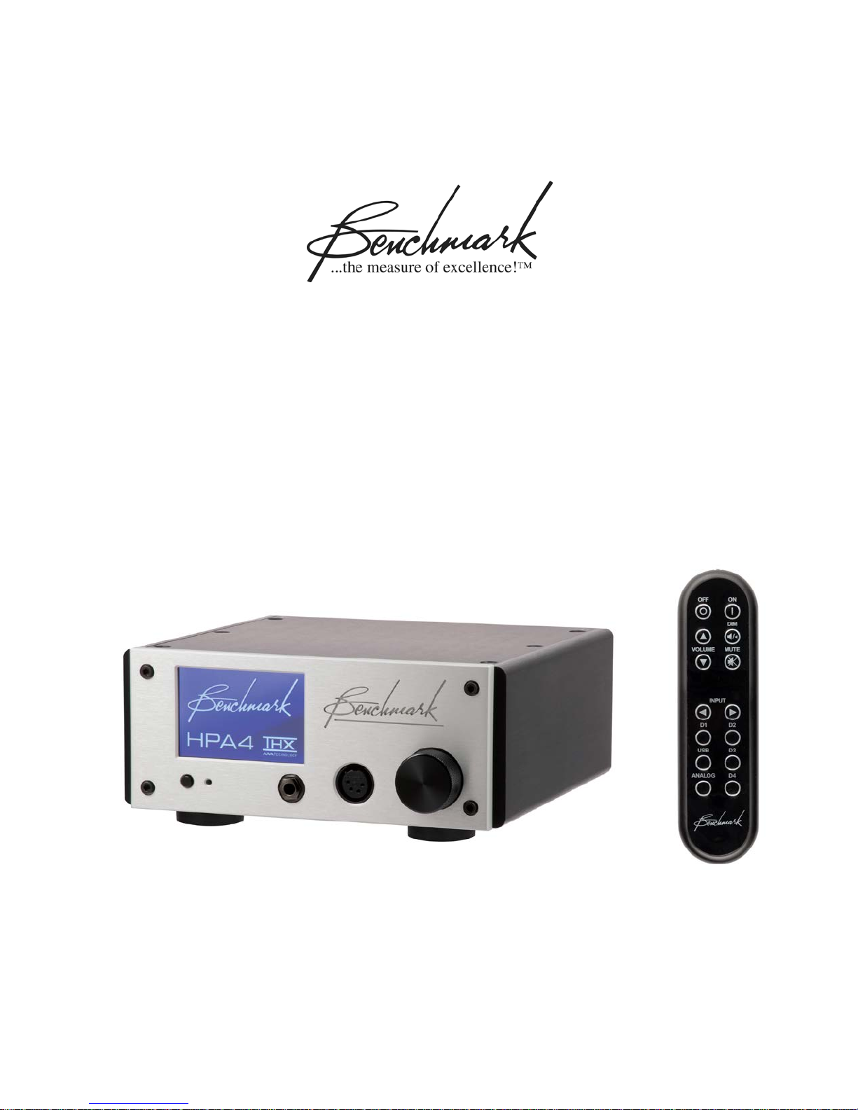
Benchmark HPA4
Instruction Manual
Reference Stereo Headphone Ampli f ier
and
Reference Line Amplifier
with
Relay Gain and Input Contr o l
Page 2

Safety Information
Fuses
CAUTION: FOR CONTINUED FIRE
HAZARD PROTECTION ALWAYS REPLACE
THE FUSES WITH THE CORRECT SIZE
AND TYPE (T 0.5A 250V 5 X 20 MM –
LITTELFUSE® SLO-BLO
EQUIVALENT). THE FUSE DRAWER
INCLUDES TWO FUSES. ALWAYS
REPLACE BOTH FUSES AT THE SAME
TIME.
AC Input Voltage Range
NOTE: THE HPA4 IS EQUIPPED WITH A
UNIVERSAL POWER SUPPLY. THERE IS
NO VOLTAGE SELECTION SWITCH. AC
VOLTAGE RANGE IS 88-264 VAC, 50-60
HZ. THE PRODUCT MAY ALSO BE
OPERATED FROM DC POWER OVER A
VOLTAGE RANGE OF 125-373 VDC.
Power Cord
CAUTION: ALWAYS USE A GROUNDED
POWER CORD. THE PRODUCT IS
EQUIPPED WITH A STANDARD IEC
POWER ENTRY MODULE. USE AN IEC
POWER CORD THAT IS EQUIPPED WITH
THE APPROPRIATE CONNECTOR FOR
YOUR LOCATION. CORDS ARE AVAILABLE
FROM YOUR DEALER.
®
HXP218.500 OR
Modifications
CAUTION: DO NOT SUBSTITUTE PARTS
OR MAKE ANY MODIFICATIONS
WITHOUT THE WRITTEN APPROVAL OF
BENCHMARK MEDIA SYSTEMS, INC.
MODIFICATION MAY CREATE SAFETY
HAZARDS AND VO I D THE WARRANTY.
CAUTION: CHANGES OR MODIFICATIONS
NOT EXPRESSLY APPROVED BY
BENCHMARK MEDIA SYSTEMS COULD
VOID THE USER'S AUTHORITY TO
OPERATE THE EQUIPMENT UNDER FCC
REGULATIONS.
Repairs
CAUTION: DO NOT SERVICE OR REPAIR
THIS PRODUCT UNLESS PROPERLY
QUALIFIED. ONLY A QUALIFIED
TECHNICIAN SHOULD PERFORM
REPAIRS.
Instruction Manual for HPA4 with 1.0.X Firmware – REV B Page 2
Page 3

Contents
Safety Information 2
Fuses 2
AC Input Voltage Range 2
Power Cord 2
Modifications 2
Repairs 2
Front Panel 5
Rear Panel 5
Features 6
Quick Start Guide 7
Main Screen 7
Balance Controls 8
Screen Navig a t ion 9
Display Settings 10
Remote Control 11
Front Panel Controls 12
Connecting Other Audio Components 13
Use Balanced Interfaces When Possible 13
Balanc ed XLR Signal Levels 13
Selecting Components for Your System 13
Use the 12V Trigger Connections 13
Connecting Benchmark Components 14
Benchmark AHB2 Power Amp 14
Benchmark DAC 14
HPA4 System Overview 24
The Ultimate Headphone Amplifier 24
The Ultimate Line Amplifier 24
Relay-Controlled Gain Stages 24
Balance Controls 24
100% Analog Signal Path 24
Fully-Balanced Signal Paths 24
Differential Amplifiers 24
Powerful Headphone Output 25
Dual Headphone Outputs 25
Ultra-Wide Bandwidth 25
Rotary Encoder 25
Convenience Features 25
12V Trigger 26
Auto-On Function 26
Casework 26
Equipment Placement 26
Auto-Ranging Power Supply 26
Audio Line Inputs 27
Balanced XLR Interfaces 27
Unbalanced RCA Interfaces 27
Input Level Matching 27
Audio Line Outputs 27
Unity Gain at 0 dB 27
15.8 dB Offset Balanced vs. Unbalanced 27
Headphone Outputs 28
Driving Two Sets of Headphones 28
Standard 1/4" TRS Connector 28
High Performance XLR4 Connector 28
Basic Features 15
Input Selection 15
Volume Control 15
Balance Adjust 15
MUTE Function 15
-20 dB DIM Function 15
Advanced Features (Settings Screens) 16
Settings Menu Screens 16
DISPLAY Settings 17
INPUT SETUP 19
RENAME INPUT 19
VOLUME SETUP 19
SETTINGS LOCK 19
POWER Settings 20
REMOTE Settings 21
ABOUT Screens 22
SPLASH SCREEN 22
RESET Screens 23
THX-888 Amplifier 29
Headphone and Hearing Warnings 29
Soft-Start Circuit 29
Protection Circuits 29
Advanced Feature Details 30
PRESET Mode 30
Auto-On Function 30
Bi-directional 12V Trigger 30
Software Version Identification 31
Performance Graphs 32
Instruction Manual for HPA4 with 1.0.X Firmware – REV B Page 3
Page 4

Specifications 50
THX-888 Headphone Outputs 50
Balanced Analog Outputs 50
Unbalanced Analog Outputs 51
Balanced Analog Inputs 51
Unbalanced Analog Inputs 51
Status Display 52
AC Power Requirements 52
Dimensions 52
Weight 52
Model Numbers 52
AC Power-Entry and Fuse Module 53
Regulatory Compliance 54
FCC Notice (U.S. Only) 54
RoHS Compliant Information 54
CE Certificate of Compliance 55
Warranty Inf o rmation 56
Benchmark 1-Year Warranty 56
Benchmark Ext en ded Warranty Options 57
Notes on Warranty Repairs 57
Instruction Manual for HPA4 with 1.0.X Firmware – REV B Page 4
Page 5
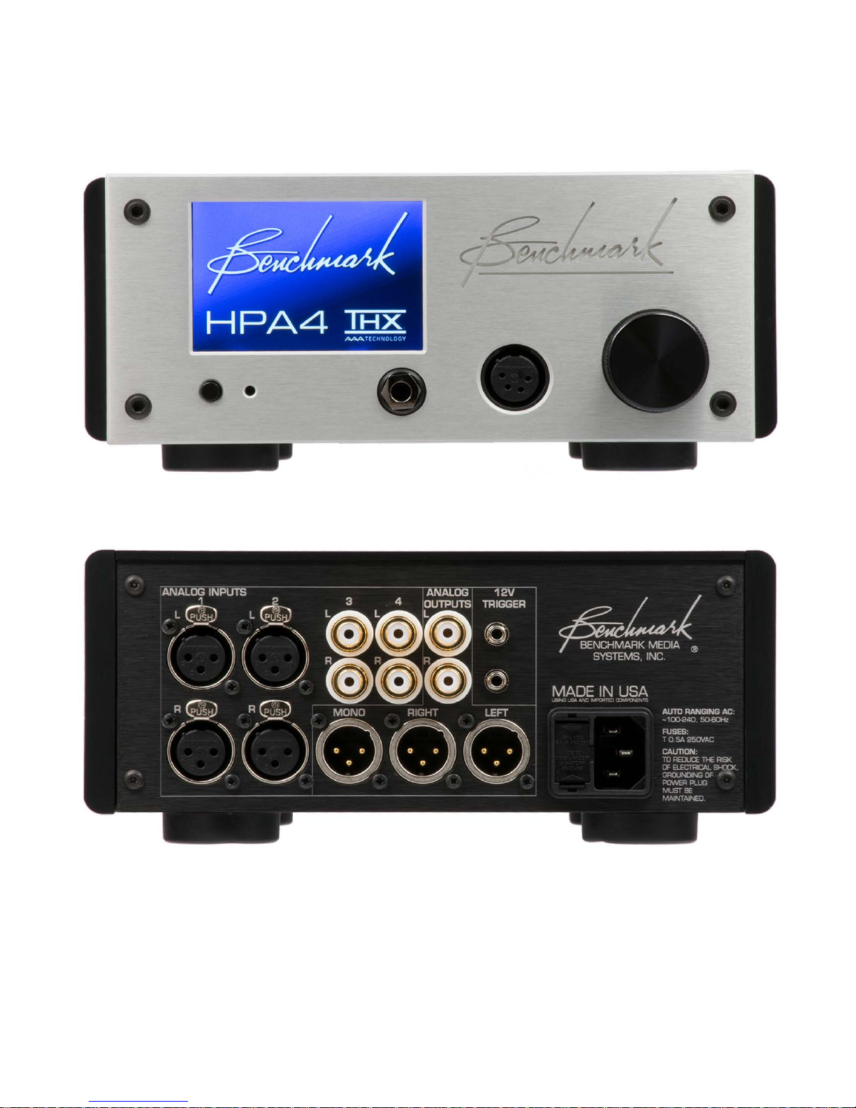
Front Panel
Rear Panel
Instruction Manual for HPA4 with 1.0.X Firmware – REV B Page 5
Page 6

Features
THX-888 Headphone Amplifier with THX AAA™ Technology
Benchmark Line Amplifier
256-Step Fully-Balanced Relay Gain Contro l , 0.5 dB Steps
Precision Timed Relay Closures
Precision Metal Film Resistors
Gold-Contact Relays
Balanced and Unbalanced I/O
6 Watts into 16 Ohm Headphones
11.5 Vrms into 300 Ohm Headphones
0.1 Hz to 500 kHz frequency respon se
SNR > 135 dB
THD < 125 dB (0.00006%) under full load
Short-Circuit Protection on Headphone Amplifier
DC Protection on Headphone Amplifier
Over-Voltage Protection on Headphone Amplifier
Over-Current Protection on Headphone Amplifier
Thermal Protection on Headphone Amplifier
Full-Color 3.5" Capacitive Touch Screen
IR Remote Control (optional)
2 Balanced Stereo Line Inputs
2 Unbalanced Stereo Line Inputs
Balanced Stereo Line Output
Unbalanced Stereo Line Output
Balanced Mono Sum Output
12V Trigger I/O – two bi-directional 12V trigger ports
AUTO-ON Function - can be programmed to turn on when AC is applied
Power Switch – very low standby power , <0.5 W at 120 VAC
High-Efficiency Low-Noise Power Supplies – 100-240 VAC, 50-60 Hz
Meets FCC Class B and CE emissions requirements
Tested for immunity to radiated and conducted RF interference
Instruction Manual for HPA4 with 1.0.X Firmware – REV B Page 6
Page 7
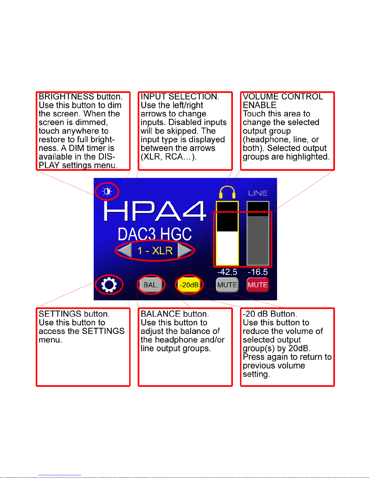
Quick Start Guide
Main Screen
Instruction Manual for HPA4 with 1.0.X Firmware – REV B Page 7
Page 8
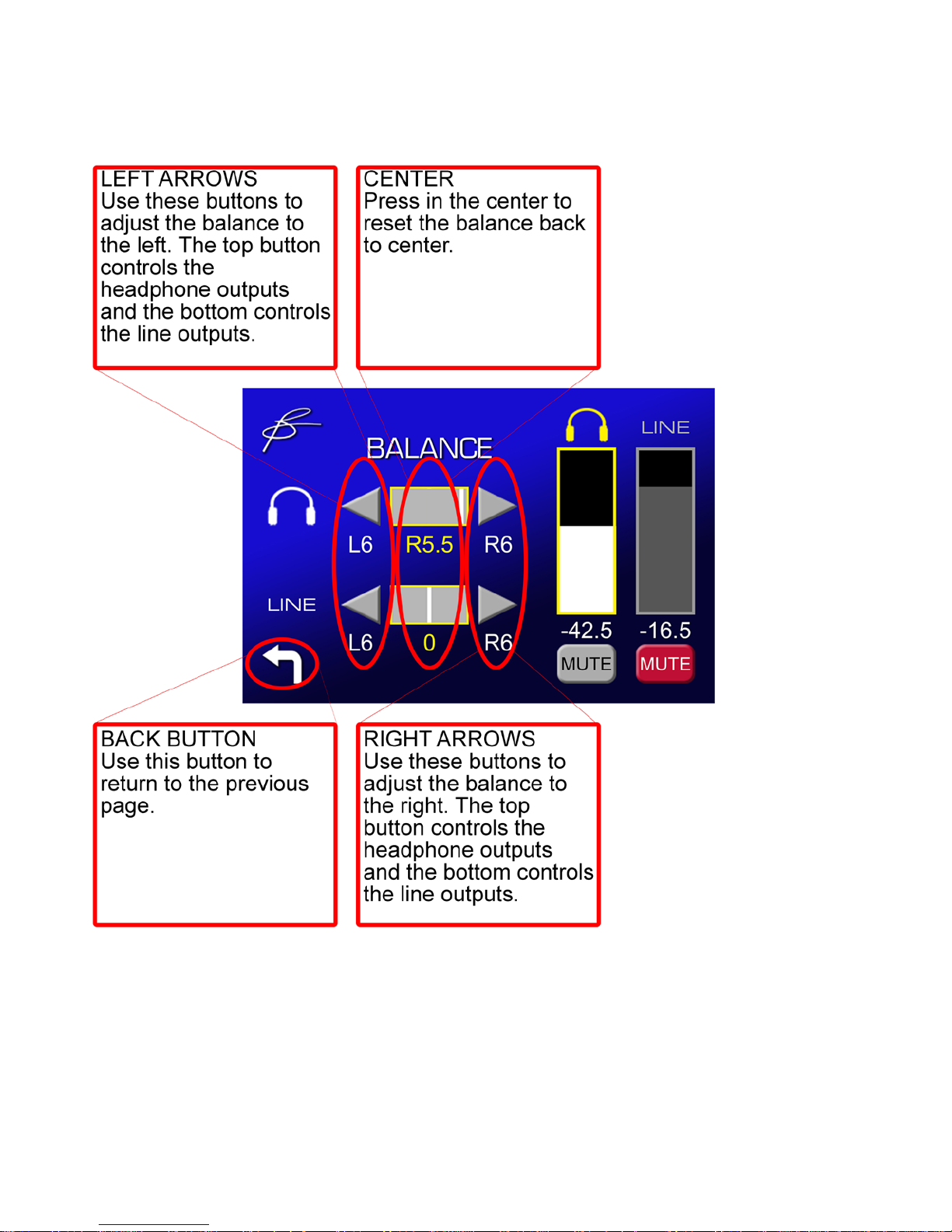
Balance Controls
Instruction Manual for HPA4 with 1.0.X Firmware – REV B Page 8
Page 9
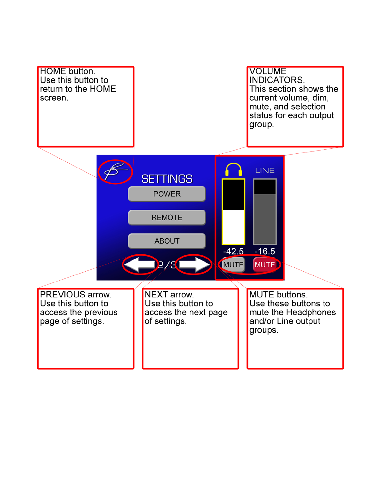
Screen Navigation
Instruction Manual for HPA4 with 1.0.X Firmware – REV B Page 9
Page 10
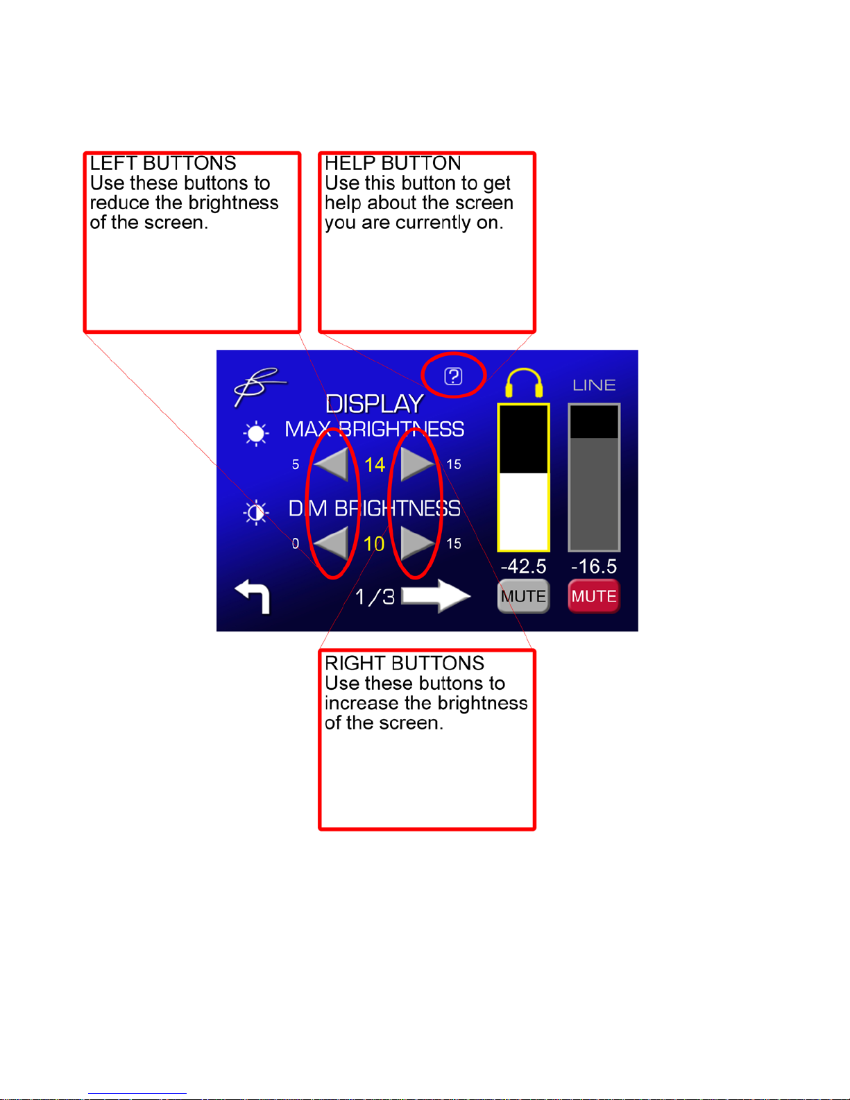
Display Settings
Instruction Manual for HPA4 with 1.0.X Firmware – REV B Page 10
Page 11
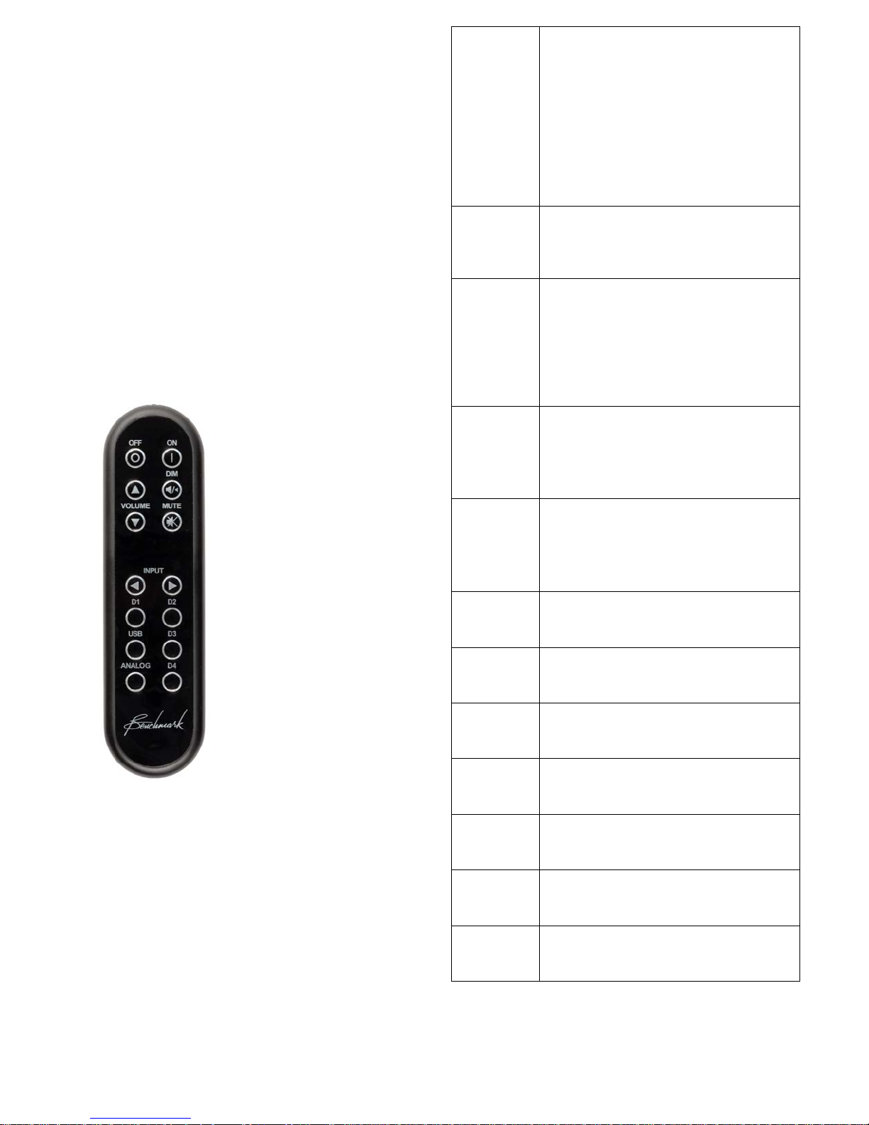
Remote Control
ON
Turns the HPA4 on. Any devices
both).
OFF
Turns the unit off. A ny devices
turn off in a controlled sequence.
VOLUME
Turns the volume up or down.
selected output group(s).
-20 dB
Toggles the -20 dB DIM function.
selected output group(s).
MUTE
Toggles the MUTE function.
selected output group(s).
INPUT
ARROWS
Scrolls through the enabled
inputs on the HPA4.
D1
Selects input D1 on DAC if
connected.
D2
Selects input D2 on DAC if
connected.
D3
Selects input D3 on DAC if
connected.
D4
Selects input D4 on DAC if
connected.
USB
Selects USB input on DAC if
connected.
Analog
Selects analog input(s) on DAC if
connected.
The remote control is designed to control the
HPA4 and any Benchmark D/A converter that
supports remote control.
The bottom six input selection buttons select
the DAC inputs if the DAC MODE is enabled
(on the REMOTE setup screen).
The HPA4 inputs are controlled with the
INPUT ARROWS.
slaved to the 12V TRIGGER will
also turn on in a controlled
sequence.
If the HPA4 is ON, this button
toggles the OUTPUT GROUP
SELECTION (headphone, line, or
slaved to the 12V TRIGGER will
The chart at the right summarizes the
functions of the IR remote control.
ARROWS
DIM
Volume up cancels MUTE and
DIM.
Volume will only be adjusted on
DIM will only be toggled on
MUTE will only be toggled on
Instruction Manual for HPA4 with 1.0.X Firmware – REV B Page 11
Page 12
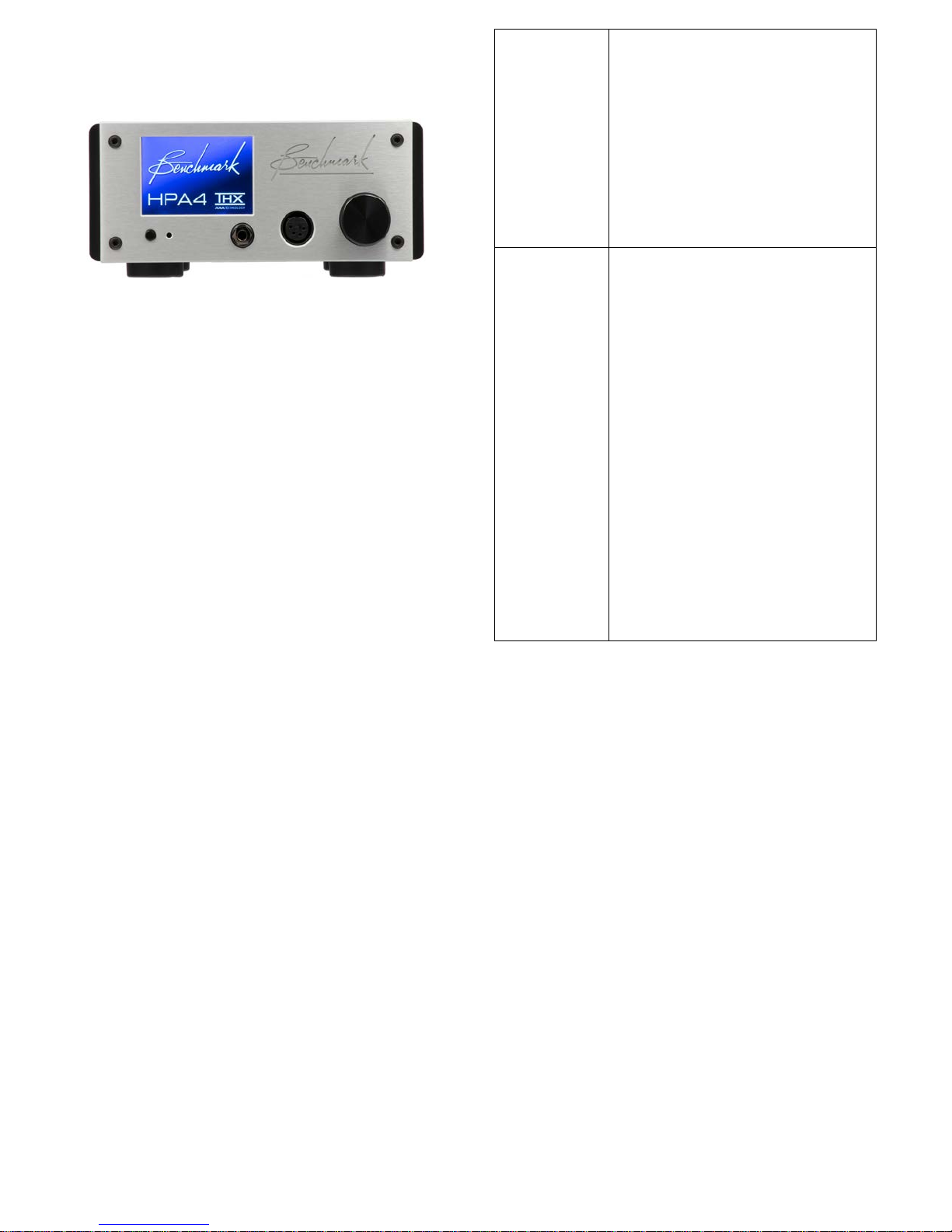
Front Panel Controls
POWER
Turns the unit on or of f.
remain on at all times) .
VOLUME
Adjusts the volume in 0.5 dB
both).
The front panel features a color touch screen,
a power switch and a volume knob.
The volume knob includes a push switch that
can be used to select which output group will
be controlled by the knob rotation.
(button)
(knob)
Any devices slaved to the 12V
TRIGGER will also turn on or
off in a controlled sequence.
If AUTO-ON is enabled, the
POWER button will toggle
MUTE on and off (the unit will
steps.
The knob features an
acceleration function. Rotate
the knob quickly and the
volume will change in larger
steps.
Tip: The IR remote sensor is located just to
the right of the power switch. Keep this
sensor unobstructed if you will be using the
optional remote control.
Tip: When AUTO-ON is enabled, a switched
AC outlet can be used to turn your system on
and off. The 12V TRIGGER I/O can be used
as a trigger output to control the power state
of additional components.
The chart at the right summarizes the
functions of the power button and
volume knob.
Volume up automatically
cancels DIM and MUTE.
Volume will only be adjusted on
selected output group(s).
Push the volume knob to select
which output group(s) will be
controlled (headphone, line, or
Instruction Manual for HPA4 with 1.0.X Firmware – REV B Page 12
Page 13

Connecting Other Audio
Components
Use Balanced Interfaces When
Possible
When possible, use balanced interfaces to
connect the primary devices in your system.
Balanced interfaces offer significant
performance advantages due to the
diffe rential signals and higher voltage lev els.
In most cases, balanced interfaces will reduce
noise in your system.
Balanced XLR Signal Levels
The HPA4 Supports Professional Signal
Levels
The XLR line inputs and ou t p ut s on the HPA4
support very hig h +28 dBu signal levels.
These high levels are used in professional
studio environments because of the high
performance that comes with using higher
voltages. All Benchmark products support
professional signal levels. Benchmark DACs
and power amplifiers wil l in t e rface to the
HPA4 using peak signal levels between +22
dBu and +24 dBu.
When possible, select devices that have
professional-level XLR interfaces. These will
usually have better SNR specifications than
devices with consumer-level XLR interfaces.
This difference in SNR is often about 10 dB.
Look for high signal levels when purchasing
audio components and check the SNR
specifications.
Use the 12V Trigger Connections
Trigger ports can be used to sequence the
power-up and power-down operations so that
all of your components turn on and off with a
single switch. The trigger ports can also
eliminate the loud pops that can occur when
devices are turned on or off in the wrong
sequence.
The trigger ports on the HPA4 are bidirectional and can be connected to inputs or
outputs on other devices. All Benchmark
trigger ports are bi-directional. Most other
products will have dedicated trigger inputs or
outputs.
If you want the HPA4 to control your system,
connect the HPA4 trigger ports to the trigger
inputs on the other dev i ces. When the HPA4
turns on, the other dev ices will follow.
The HPA4 Also Supports Consum er S ig n a l
Levels
The stepped gain controls in the HPA4 have
excellent noise performance and provide a
wide dynamic range. This allows the
simultaneous use of consumer-level and
professional-level balanced interfaces.
Professional XLR interfaces are usually 10 dB
hotter than consumer-level XLR interfaces.
The stepped gain control in the HPA4 can
easily provide a 10 dB boost or cut without
sacrificing performance.
If you want to use another device as a trigger
master, connect its trigger output to one of
the trigger ports on the HPA4. When this
other device turns on or off, the HPA4 will
follow.
In an all-Benchmark system, jus t connect the
trigger ports in a star or daisy chain. The
system can be turned on or off using the
power switch on any Benchma rk device. This
is one of the advantages provided by
Benchmark's bi-directional trigger ports.
Selecting Components for Your
System
Select devices with balanced XLR inputs and
outputs. Balanced interfaces are vastly
superior to unbalanced RCA interfaces.
Instruction Manual for HPA4 with 1.0.X Firmware – REV B Page 13
Page 14

Connecting Benchmark
Components
Benchmark AHB2 Power Amp
1. Set the SENSITIVITY switch on the
AHB2 to 22 dBu (switch in the down
position).
2. Connect either trigger port on the
AHB2 to eith er trigger port on the
HPA4. If you are using two AHB2
amplifiers in bridged mono, the second
amplifier can be connected to an
unused trigger port on the HPA4 or
the other amplifier.
3. C onnect the left and right XLR outputs
on the HPA4 to the left and right XLR
inputs on the amplifier. If you are
using two amplifiers in bridged mono
mode, connect the cables to the
MONO input on each amplifier.
4. If you are using a single AHB2, set
the MODE switch on the back of the
amplifier to STEREO. If you are using
two AHB2 amplifiers, set the MODE
on each to MONO.
Tip: If you turn the system on or off using
the HPA4 or the remote control, the
amplifier s will follow. If you will be listening to
headphones and you wish t o turn off the
amplifiers, you can d o this: Just press the
POWER buttons on each amplifier and they
will turn off without turning off the HPA4.
Tip: If you want to shut down the entire
system using the POWER switch on an
amplifier, you will need to press and hold the
switch for 3 seconds.
can be used to turn the entire system
on or off in a sequenced fashion.
3. Use XLR cables to connect the DAC to
Input 1 on the HPA4. This input
supports a special DAC compatibility
mode.
4. If your DAC has a 'DAC-ONLY MODE',
enable this mode. This will bypass the
VOLUME, MUTE and DIM controls on
the DAC.
5. If your DAC does not have a 'DACONLY MODE', set every input on the
DAC to 'HT' mode, or 'CALIBRATED'
mode. This will bypass the volume
control on the DAC, but IR remote
MUTE and DIM controls may still be
active on some DAC models.
If you have a Benchmark DAC with remote
control, the HPA4 has a special mode of
operation that allows both devices to be
controlled from a single remote. If your
Benchmark DAC has remote control, follow
this additional step:
6. Go to the REMOTE settings screen on
the HPA4 and select 'BENCHMARK
DAC ON XLR1'. The Benchmark IR
remote control will now control both
devices. The HPA4 will pro v id e
volume control and switching between
analog inputs. The DAC will provide
switching between digital inputs.
Tip: Use the dedicated digital input select
buttons (USB, D1, D2, D3 and D4) to select
digital inputs on the DAC. Use the INPUT
scroll buttons on the remote to select analog
inputs on the HPA4. Use the dedicated
ANALOG button on the remote to sel ect the
analog inputs on the DAC (if a ny).
Benchmark DAC
1. Set the XLR output attenuators in the
DAC to 0 dB. You will need to open
the cover on the DAC if these jumpers
need to be changed.
2. If your DAC has a trigger port, connect
it to either port on the HPA4. This
trigger connection provides a control
link so that the remote, DAC or HPA4
Instruction Manual for HPA4 with 1.0.X Firmware – REV B Page 14
Tip: We recommend using the direct analog
inputs on the HPA4 before using the analog
inputs on the back of the DAC. The direct
connections on the back of the HPA4 will
provide better performance.
Tip: Use the VOLUME UP key on the remote
if you wish to release the MUTE and DIM on
all devices.
Page 15

Basic Features
MUTE Function
Input Selection
Use the input selection arrows to scroll
through the enabled inputs. These arrows are
displayed on the HOME screen and are also
available on the REMOTE.
Volume Control
The volume of the headphone and line output
groups can be adjusted independently. The
bar graphs show the current volume settings.
The volume controls are enabled when the
bar graph(s) are highlighted.
Select the OUTP UT G R OUP(S)
Press the volume knob or touch the bar
graphs to select the OUTPUT GROUP that
you would like to adjust (headphones, line or
both). If you are using the remote, press the
ON button to toggle between output groups.
The headphone output and line output groups
have separate MUTE buttons on the touch
screen. Each MUTE button is highlighted in
red when the output group is muted.
When MUTE is toggled on, the audio is
immediately muted. When MUTE is toggled
off, the volume will fade back up to the
original level.
The MUTE key on the remote will mute the
selected output group(s).
Tip: Turn the VOLUME up to release MUTE
and return to the prior volume setting.
-20 dB DIM Function
The DIM function reduces the level of the
selected output group(s) by 20 dB. When
DIM is toggled on, the volume fades down by
exactly 20 dB. When DIM is toggled off, the
volume fades back up to the original lev e l.
Adjust the volume
Rotate the volume knob or use the remote
control to adjust the volume of the selected
output group(s).
Balance Adjust
Press the BAL button on the HOME screen to
change the L/R balance of the headphone
and/or line outputs. These are independently
adjustable.
The volume bar graph will be displayed in
yellow when DIM is on.
Tip: Turn the VOLUME up to release DIM
and return to the prior volume setting.
Instruction Manual for HPA4 with 1.0.X Firmware – REV B Page 15
Page 16
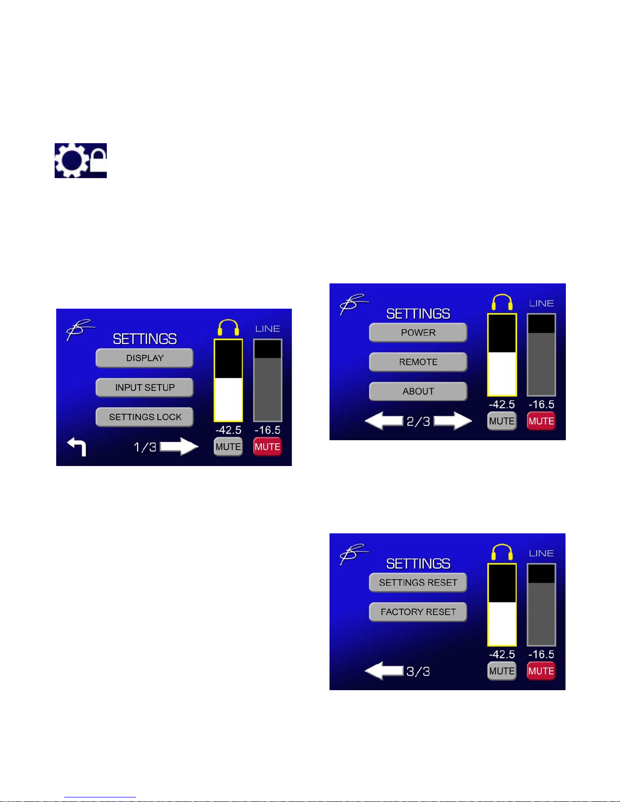
Advanced Features (Settings Screens)
Press the gear icon on the HOME screen to access the advanced features.
If the advanced features have been locked, a locked gear icon will be displayed on the
HOME screen. Press and hold the locked gear icon for 3 seconds to access the advanced
features.
Settings 2
Settings Menu Screens
• Power (Auto-On, Trigger)
Settings 1
• Display Settings
• Input Setup
• Lock/Unlock Advanced Settings
• Remote (IR Enable, DAC Mode)
• About (System Information)
Settings 3
• Reset Advanced Settings
• Full Factory Reset
Instruction Manual for HPA4 with 1.0.X Firmware – REV B Page 16
Page 17
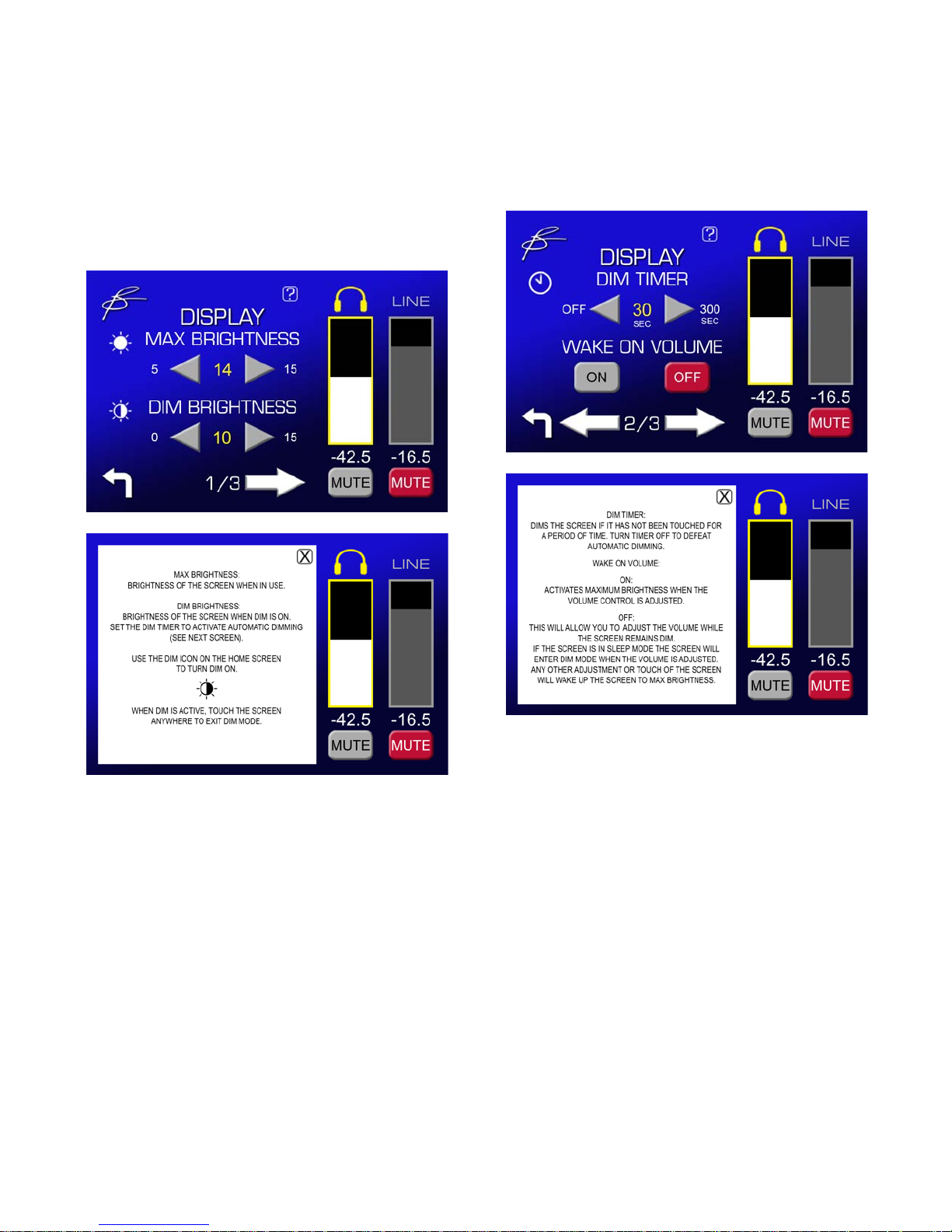
DISPLAY Settings
Display Settings 1
• Maximum Screen Brightness
• Screen Brightness when Dimmed
DISPLAY Settings 2
• Screen Dim Timer
• 'WAKE ON VOLUME' Function
Instruction Manual for HPA4 with 1.0.X Firmware – REV B Page 17
Page 18
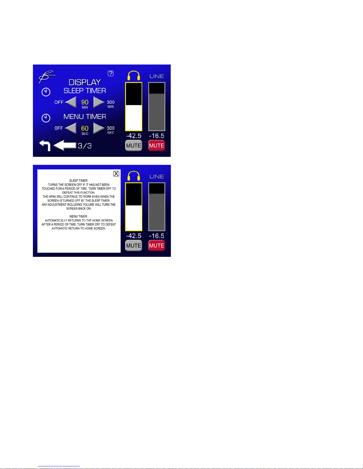
DISPLAY Settings 3
• Display Sleep Timer (screen off)
• Menu Timer (return to home page)
Instruction Manual for HPA4 with 1.0.X Firmware – REV B Page 18
Page 19
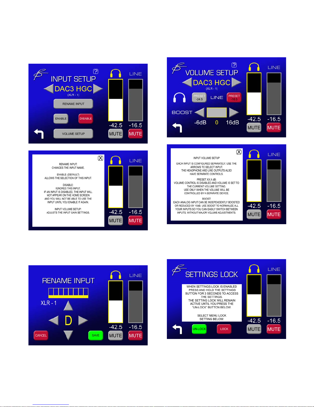
INPUT SETUP
VOLUME SETUP
• Rename Inputs
• Disable/Enable Inputs
• Volume Setup for Each Input
• Volume Preset - Enable/Disable
• Boost Adjust (input volume offset)
RENAME INPUT
• Input Name Edit
SETTINGS LOCK
• Lock/Unlock Advanced Settings
Instruction Manual for HPA4 with 1.0.X Firmware – REV B Page 19
Page 20
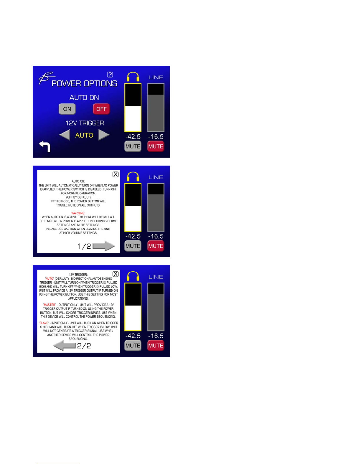
POWER Settings
• Auto-On - Enable/Disable
• 12V Trigger Mode
Instruction Manual for HPA4 with 1.0.X Firmware – REV B Page 20
Page 21
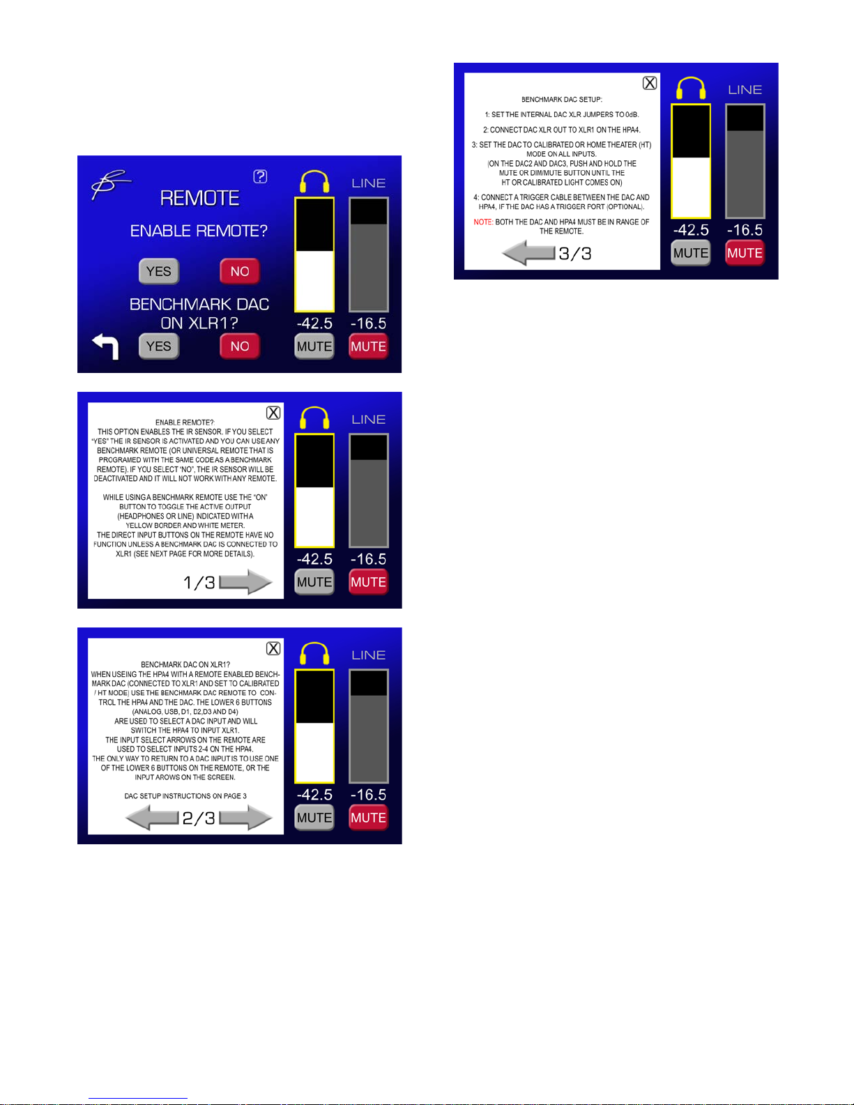
REMOTE Settings
• Enable IR Remote Control
• Integrate with Benchmark DAC
Instruction Manual for HPA4 with 1.0.X Firmware – REV B Page 21
Page 22
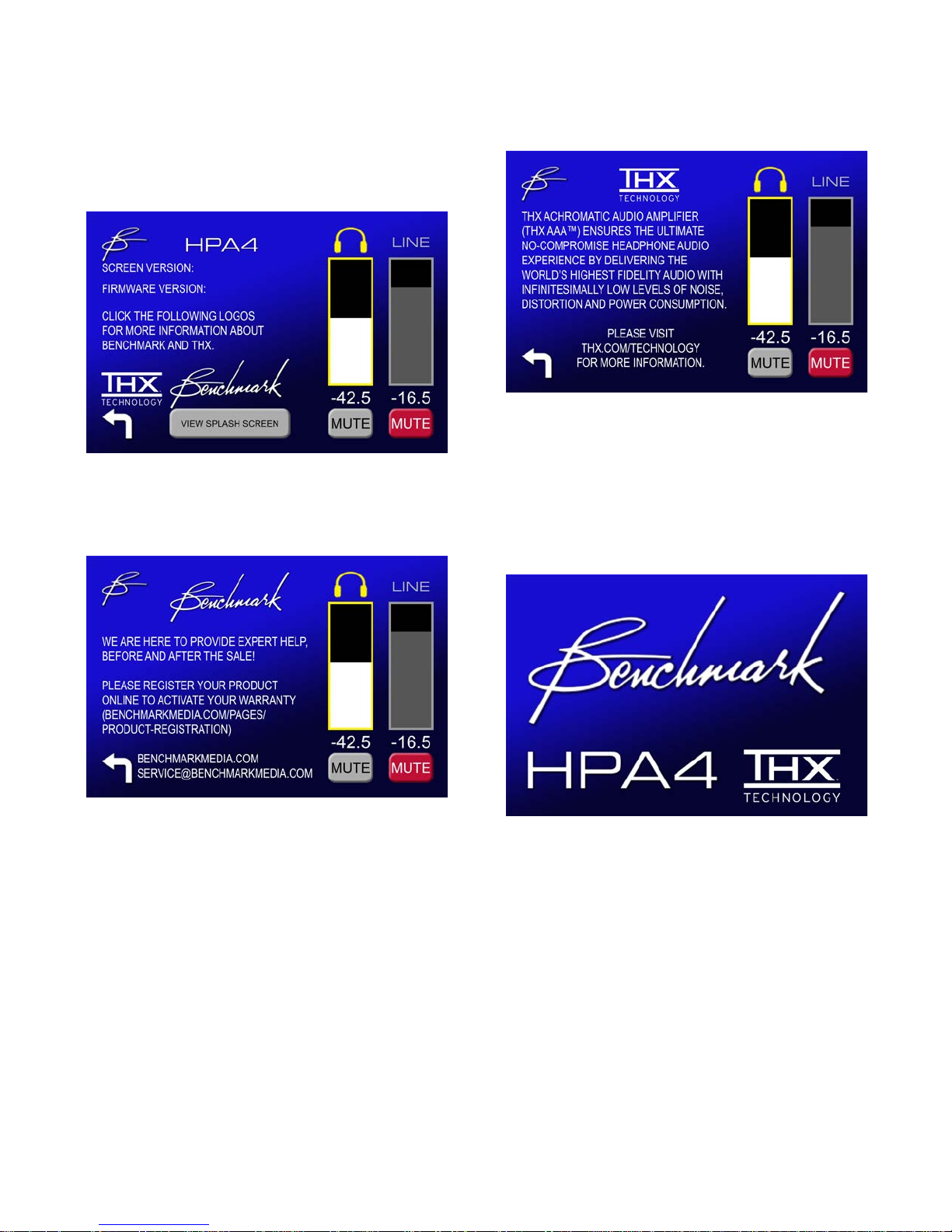
ABOUT Screens
ABOUT THX
ABOUT
• Firmware Version (hardware drivers)
• Software Version (touch screen)
ABOUT BENCHMARK
• Benchmark Contact Information
• THX AAA™ Technology Information
SPLASH SCREEN
• Unit is Turning On or Off, Audio is
Muted
• May be manually enabled from ABOUT
screen (this does not mute the audio,
touch the screen to exit).
Instruction Manual for HPA4 with 1.0.X Firmware – REV B Page 22
Page 23
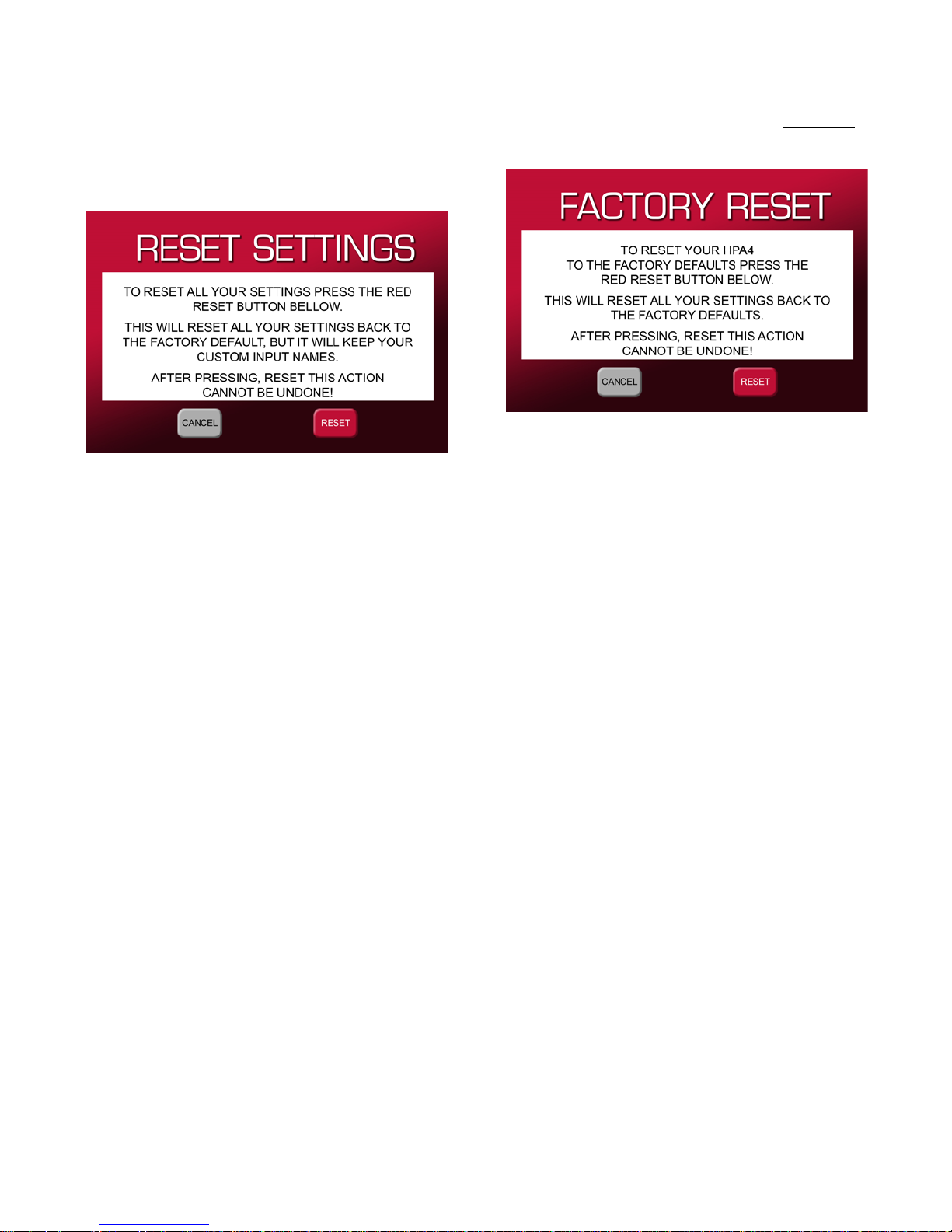
RESET Screens
FACTORY RESET
RESET SETTINGS
• Reset all Advanced Settings Except
Input Names
• Reset all Advanced Settings Including
Input Names
Instruction Manual for HPA4 with 1.0.X Firmware – REV B Page 23
Page 24

HPA4 System Overview
The Ultimate Headphone Amplifier
Benchmark Media Systems, Inc. and THX,
Ltd. have partnered to introduce the
Benchmark HPA4 headphone/line amplifier
featuring TH X Achromatic Audio Amplifier
(AAA™) technology.
THX AAA™ reduces harmonic,
intermodulation, and crossover distortion by
20 to 40 dB to guarantee a realistic and
fatigue-free listening experience. It
accomplishes this using a patented feedforward topology to null conventional
distortion and noise mechanisms, resulting in
the world's most linear amplifier. THX
AAA™ allows the amplifier to reach its
maximum output power and sound pressure
level (SPL) without producing the distortion
that normally accompanies increased output
levels in traditional amplifiers.
Featuring the flagship THX-888 amplifier
design, the revolutionary HPA4 headphone
amplifier incorporates the same THX
AAA™ technology that Benchmark uses in the
AHB2 power amplifier. The HPA4 delivers
sonic perfection. Hear the music without any
contamination from electronic noise or
distortion. The HPA4 delivers power, audio
fidelity, speed and accuracy over an utterly
silent background.
The Ultimate Line Amplifier
The THX-888 amplifier is driven by a
Benchmark line amplifier that features relay
gain control, relay input selection, and relay
muting. It is designed to deliver the lowest
possible distortion and noise over a wide
range of volum e set tings. We believe that the
HPA4 line amplifier is the fin est available at
any price.
Relay-Controlled Gain Stages
The relay-controlled gain stages provide 256
volume steps in precise 0.5 dB increments.
These gain stages feature the finest goldcontact relays available.
Relay closures are precisely timed to deliver
silky-smooth volume changes. No other relaycontrolled gain stage offers this level of
precision or performance.
The HPA4 includes 4 independent fullybalanced 256-step volume controls: two for
the L&R headphone outputs, and two for the
L&R line outputs. To make this all happen, the
HPA4 includes a total of 64 precision relays.
Balance Controls
The line and headphone outputs feature
independent balance controls that are
adjustable in 0.5 dB steps.
100% Analog Signal Path
The HPA4 is 100% analog. It is designed to
be driven from an external D/A converter or
an external analog so urce. The HPA4 is
designed to provide the ultimate analog signal
path between inputs and outputs. The HPA4
eclipses the performance of typical high-end
preamplifiers by achieving much lower noise
and distortion.
Fully-Balanced Signal Paths
The internal signal paths are fully balanced.
The inputs are routed to a balanced pair of
precision differential amplifier s. These drive
two sets of fully-balanced 256-step volume
controls. The balanced outputs from the
volume controls drive the headphone
amplifier and line output drivers.
Differential Amplifiers
The HPA4 features precision differential
amplifiers on all inputs. These reject
common-mode noise, common-mode
distortion and common-mode interference.
This feature is especially important when
using D/A converters that lack their own
differential amplifiers.
Benchmark D/A converters include differential
amplifiers, but many competing converters
Instruction Manual for HPA4 with 1.0.X Firmware – REV B Page 24
Page 25

lack these stages which remove the commonmode distortion produced by D/A chips.
Powerful Headphone Output
The THX-888 amplifier in the HPA4 can
cleanly deliver high power and current into
low-impedance headphones. It can also
deliver the high voltage required by very lowsensitivity headphones.
High Power
The HPA4 delivers 6 Watts into 16 Ohms.
Best of all, there is no increase in THD when
driving low-impedance h eadphones. The THX
AAA™ technology keeps the output distortion
free while driving very difficult low-impedance
loads.
High Current
Low-impedance headphones may also require
high current due to difficult phase a ngles
presented by non-resistive driver loading. The
HPA4 can provide peak currents exceeding
1.5 amps. This is more than enough current
to drive difficult headphones with ease.
Ultra-Wide Bandwidth
The frequency response of the HPA4 extends
from 0.1 Hz to 500 kHz. This extended range
keeps the phase response extremely accurate
over the entire audio band. The entire audio
spectrum is delivered with the proper timing.
Bass is delivered with the correct timing
relative to other frequencies. Most audio
products deliver the bass slightly late. Bass
that arrives late tends to mask highfrequency details. In contrast, bass that
arrives with the correct timing will sound
deep, full and well damped. For this reason,
all Benchmark products feature low-frequency
extension to 0.1 Hz.
The extreme 500 kHz high-frequency
extension delivered virtually perfect timing at
the high end of the audio spectrum. High
frequencies are delivered with precise timing
relative to low and mid frequencies. In
addition, the left-right differential phase is
virtually perfect at 20 kHz. These timing
characteristics preserve the precise placement
of voices within a well-defined 3D stereo
image.
High Voltage
High-impedance headphones may not draw
much power or much current, but they may
demand high drive voltages. The HPA4
delivers 11.9 Vrms into 300-Ohm
headphones. This is plenty of voltage to drive
headphones with very low sen sitivities.
Dual Headphone Outputs
The HPA4 features a traditional 1/4" TRS
headphone jack and a 4-pin XLR jack.
The 4-pin jack provides separate r eturns for
the left and right channels. Each output
channel is driven differentially relative to its
return pin on the 4-pin jack.
We recommend using the 4-pin jack because
the XLR connector provides lower contact
resistance than the TRS connector.
Rotary Encoder
The volume control knob features a highquality optical encoder that is rated for he a vy
use. An acceleration feature makes it easy to
move through the 256 volume steps while
maintaining 0.5 dB/step resolution. A press of
the control knob toggles between headphone
volume, line volume, or both.
Convenience Features
The HPA4 includes independent on-screen
mute buttons for the headphone and line
outputs. Both can also be muted with the
volume knob or with the optional remote
control.
The HPA4 includes an on-screen -20 dB dim
button that fades the level down by 20dB.
This function provides a temporary volume
reduction and an easy return to the previous
Instruction Manual for HPA4 with 1.0.X Firmware – REV B Page 25
Page 26

listening level. This control makes it easy to
transition between a normal listenin g level
and a background level. The DIM function is
also accessible from the optional remote
control.
Inputs may be renamed and unused inputs
may be disabled. Input levels can be trimmed
to provide input-to-input level matching.
Screen brightness is adjustable and timers
can be set to dim or shut off the display. The
setup screen can be locked to prevent access
to advanced features.
12V Trigger
Equipment Placement
Locate the HPA4 where the side panels are
exposed to air. These panels help dissipate
heat and should not be obstructed.
The IR sensor for the remote control is
located to the right of the power switch on
the front panel. Make sure this is visible from
your listening position.
The HPA4 does not emit strong magnetic
fields and for this reason, it will not create
interference with audio devices that are
placed above or below the HPA4.
The HPA4 has two trigger ports. These can
be connected to other audio components so
that the entire audio syst em can turn on and
off in a sequenced f as hio n. The HPA4 will pull
the trigger I/O to 12 volts DC while the HPA4
is on. If the HPA4 is off and an external
device pulls the trigger I/O to 12 volts, the
HPA4 will turn on.
The trigger ports are bi-directional by default,
but they can be configured as inputs or
outputs.
Auto-On Function
The HPA4 can be programmed to
automatically turn on when AC power is
applied.
Casework
The HPA4 is available with a black or silver
faceplate and is designed to match the
Benchmark AHB2 power amplifier. It
occupies the same footprint as the
Benchmark DAC1, DAC2 and DAC3
converters. The case features a milled
faceplate and milled sides. Top, bottom, and
rear panels are made from thick aluminum
and feature a brushed texture. The HPA4 is
built to last and will be a fine addition to your
listening space.
Please note that most power amplifiers emit
strong magnetic fields. In most cases, the
HPA4 should not be stacked directly above or
below a power amplifier. Allow at least a few
inches of space above or below a power
amplifier. The magnetic fields produced by
the power amplifier may interfere with the
HPA4. One exception is the Benchmark
AHB2 power amplifier. The HPA4 can be
stacked directly above or below an AHB2
without any risk of m agnetic interference
from the power amplifier.
The HPA4 can also be stacked directly above
or below Benchmark DAC2 or DAC3
converters. The older DAC1 series converte rs
emit stronger magnetic fields and should not
be stacked directly above or below the HPA4.
Auto-Ranging Power Supply
The internal power supply automatically
senses the AC line voltage. There are no
settings or fuses to change for international
operation. Select a grounded IEC power cord
that matches the AC outlets in your country.
Instruction Manual for HPA4 with 1.0.X Firmware – REV B Page 26
Page 27

Audio Line Inputs
The HPA4 features two stereo balanced XLR
analog inputs and two stereo unbalanced RCA
analog inputs.
Balanced XLR Interfaces
Balanced interfaces use higher signal levels
and for this reason, they provide better signal
to noise ratios. Balanced interfaces also
provide immunity from ground loop induced
hum and buzz. In general, balanced
interfaces are vastly superior to unbalanced.
Select products with balanced interfaces a nd
avoid the use of unbalanced interfaces
whenever possible.
Unbalanced RCA Interfaces
Given the widespread consumer use of
unbalanced RCA inter connects, we have made
every effort to extract the highest possible
performance from these antiquated consumer
audio interconnects.
The unbalanced RCA inputs on the HPA4 are
connected to balanced receivers. These
balanced receivers provide significant
immunity to ground loop induced hum and
buzz. This topology provides the RCA inputs
with some of the advantages of fully-balanced
interfaces. Nevertheless, unbalanced
interfaces can never match the full
performance of professional-grade balanced
interfaces.
15.8 dB default boost doesn't work in your
system, individual inputs can be trimmed by
+/- 10 dB in 0.5 dB steps using the BOOST
function. The boost value does not impact the
audio performance. It is equivalent to
automatically rotating the volume control
when the input is changed. The boost value
changes the way the vo lume is numerically
displayed.
Tip: We recommend using professional-grade
balanced XLR interconnects that provide +24
dBu at 0 dBFS. Consumer-grade balanced
XLR interconnects operate at levels that are
about 10 dB lower (4 Vrms or +14.2 dBu at 0
dBFS). Consumer RCA interconnects operate
at levels that are about 16 dB lower (2 Vrms
or 8.2 dBu at 0 dBFS). High signal levels and
diffe rential signal ing are essential in highresolution audio systems. RCA interconnects
will limit system performance.
Audio Line Outputs
The HPA4 features a stereo pair of balanced
XLR outputs and a stereo pair of unbalanced
RCA outputs. It also includes a balanced
mono sum output. The mono sum can be
used to drive a powered subwoofer.
The balanced outputs are designed to operate
at professional levels (+24 dBu at 0 dBFS).
The unbalanced outputs are designed to
operate at consumer levels (2 Vrms at 0
dBFS).
If your D/A converter and/or power amplifier
lack balanced interfaces, it is a good
indication that these devices are not true
high-resolution audio products. Look for
professional-grade balanced interfaces that
support 24 dBu signal levels.
Input Level Matching
By default, the unbalanced inputs on the
HPA4 are automatically boosted by 15.8 dB
so that they will match the level of the
professional-grade balanced inputs. If the
Instruction Manual for HPA4 with 1.0.X Firmware – REV B Page 27
Unity Gain at 0 dB
If the volume control is set to 0 dB, the XLR
output levels will be identical to the XLR input
levels feeding the system. Likewise, the RCA
output levels will be identical to the RCA input
levels feeding the system.
15.8 dB Offset Balanced vs.
Unbalanced
Balanced outputs are 15.8 dB hotter than the
unbalanced outputs. Balanced inputs are
assumed to be 15.8 dB hotter than
unbalanced.
Page 28
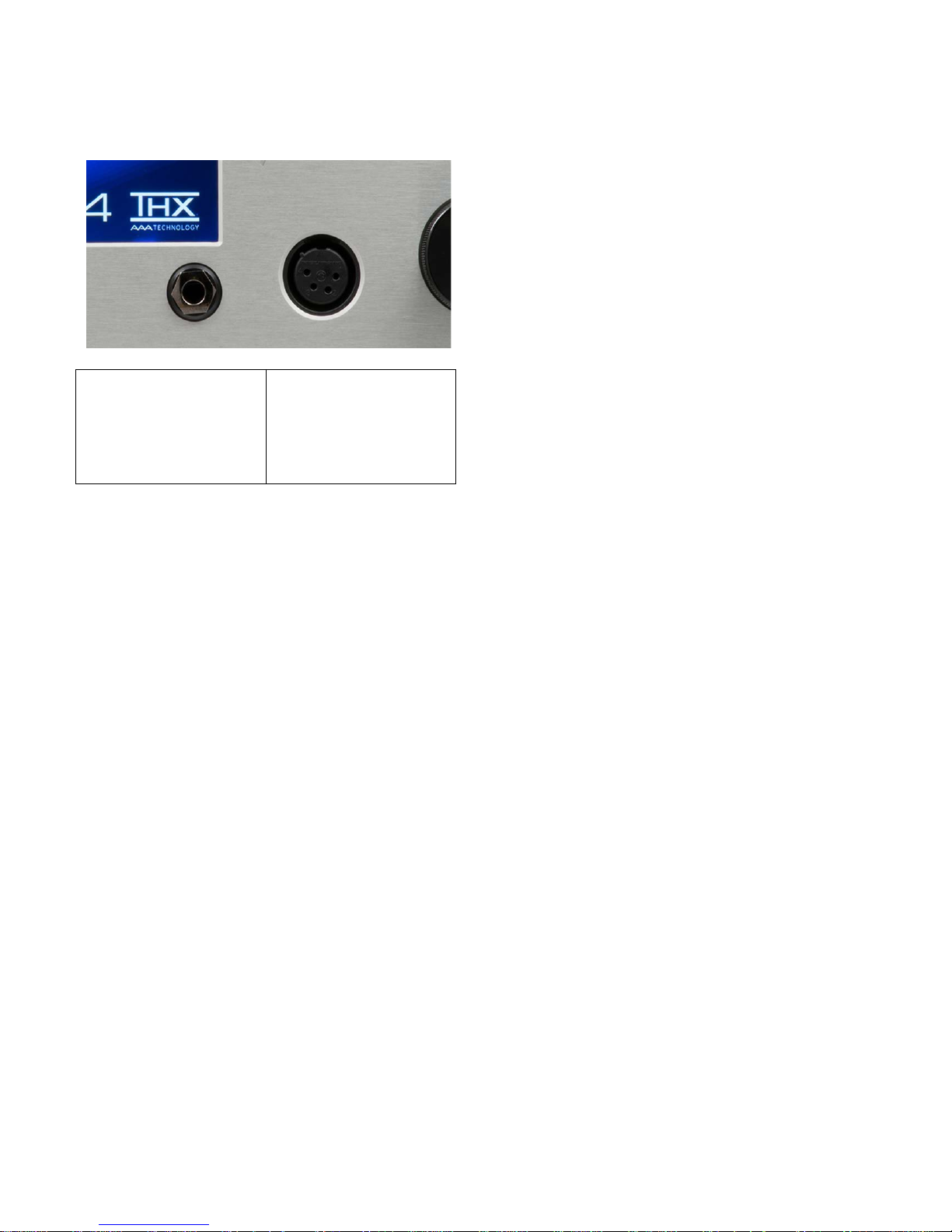
Headphone Outputs
The left-hand jack is
The right-hand jack is
channel.
the headphone plug. Gold plated plugs are
highly recommended.
The traditional 1/4" TRS connector uses the
sleeve as a common ground for the left and
right channels. This connection carries twice
the current carried by the other contacts.
High contact resistance at the sleeve
connection can cause distortion on both
channels.
a traditional 1/4" TRS
headphone jack. The
L & R channels share
a common return.
a 4-pin XLR
headphone jack that
features dedicated
returns for each
Driving Two Sets of Headphones
The HPA4 has more than enough power and
output current to drive two sets of
headphones simultaneously. The two
headphone jacks can be used simultaneously,
but the two sets of headphones need to have
simila r sensitivities. If the sensitivities are
different, one set of headphones will play
louder than the other.
The main purpose of the second connector is
to provide a high-performance alternative to
the traditional TRS phone jack.
Standard 1/4" TRS Connector
With many TRS plugs we have found that the
tip connectio n is somewhat less reliable than
the ring connection. This means that there is
a higher chance of distortion being added to
the left channel.
Tip: If the TRS plug is gold plated, clean and
in good condition, the TRS jack can match the
performance of the XLR4. When conditions
are less than ideal, the TRS contact resistance
can be the largest source of distortion in the
entire HPA4 headphone system.
High Performance XLR4 Connector
The 4-pin XLR connector provides dedicated
pins for the left and right returns. There are
no shared connections . In the HPA4, the left
and right outputs are differentially driven
relative to their respective returns.
The separate returns eliminate any interaction
between the channels. More importantly, the
XLR4 connector provides much lower contact
resistance than the traditional 1/4" TRS
connector.
The HPA4 included a traditional 1/4" tip-ringsleeve (TRS) headphone jack. This provides a
convenient output that is compatible with
most headphone cords. Slightly higher
performance is available from the XLR4
connector.
In our tests we have found that the TRS
contacts can occasionally produce more
distortion than the entire HPA4 headphone
amplifier. We have selected one of the
highest quality TRS jacks available, but the
performance of the TRS jack is highly
dependent upon the quality and condition of
Instruction Manual for HPA4 with 1.0.X Firmware – REV B Page 28
Our tests have shown that XLR jack and plug
combinations provide very reliable electrical
connections. No measurable distortion was
produced by the XLR4 connector in any of our
tests.
Tip: The Volume Control simultaneously
adjusts the level for both headphone jacks. If
two listeners will be simultaneously using the
headphone outputs, we recommend using
headphones with identical or very similar
voltage sens itivitie s.
Page 29

THX-888 Amplifier
Protection Circuits
The headphone outputs are driven by the
flagship THX-888 amplifier. This headphone
amplifier incorporates the same patented THX
AAA™ technology that Benchmark uses in the
AHB2 power amplifier. The HPA4 is designed
to deliver power, audio fidelity, speed and
accuracy over an utterly silent background.
THX AAA™ reduces harmonic,
intermodulation, and crossover distortion by
20 to 40 dB to guarantee a realistic and
fatigue-free listening experience. It
accomplishes this using a patented feedforward topology to null conventional
distortion and noise mechanisms. THX
AAA™ allows the amplifier to reach its
maximum output power and sound pressure
level (SPL) without producing the distortion
that normally accompanies increased output
levels in traditional amplifiers.
Headphone and Hearing Warnings
CAUTION: The THX-888 headphone
amplifier in the HPA4 is cap able of d elivering
peak-to-peak voltages of about 25 Volts. It is
also capable of delivering 1.5 Amps. These
levels are high enough to damage most
headphones (and your ears). Use caution
when adjusting playback levels.
CAUTION: Do not drive a set of headphones
while they are sitting on a desk or stand. It is
easy to accidentally overdrive them. This is
especially true when you have set the
headphones aside while listening to speakers.
Mute or unplug your headp hones when they
are not in use!
The THX-888 headphone amplifier has
several circuits that are intended to protect
the amplifier from overloads and short
circuits. Fault cond itions will disable a pair of
output relays which wi ll disconnect the
amplifier from the output jacks. The output
relays are only energized when all conditions
are normal.
Over Current Protection
If the output current exceeds 1.5 Amps on
either output channel, the protection re lays
will disconnect the amplifier from the output
jacks. The connection will be restored after a
few seconds. The protection cycle will repeat
if necessary. This protection mode may
engage if headphones are plugged into the
1/4" TRS jack while audio is playing. TRS
plugs can cause a temporary short-circuit
condition while the plug is being inserted.
Clip Detection
If the headphone amplifier is driven into
clipping, the protection relays will disconne ct
the amplifier from the output jacks. If clipping
ceases, the connection will be restored after a
few seconds.
DC Detection
If DC is detected on the output of the
headphone amplifier, the protection relays
will disconnect the amplifier from the o utput
jacks. This protection circuit is intended to
protect the headphones in the unlikely event
of a catastrophic component failure.
Soft-Start Circuit
The THX-888 uses relays to mute the
headphone output until the power supplies
have reached normal voltages.
Instruction Manual for HPA4 with 1.0.X Firmware – REV B Page 29
Temperature Limiting
If the THX-888 is severely overloaded for a
period of time, component temperatures may
start to climb. If safe operating temperatures
are exceeded, the protection relays will
disconnect the amplifier from the output
jacks. After the drivers have cooled, the
connection will be restored. This cooling cycle
may take several minutes.
Page 30

Advanced Feature Details
PRESET Mode
The 12V TRIGGER I/O can be connected to
the trigger input or output ports on a D/A
converter, power amplifier, or both.
The PRESET mode sets the output level to a
fixed level. There are separate presets for the
headphone and line outputs. Each input has
two preset buttons. One for the headphone
outputs and one for the line outputs. These
can be set on the VOLUME SETUP screen
which is accessed from the INPUT SETUP
screen.
Auto-On Function
The HPA4 can be programmed to
automatically turn on whenever AC power is
applied. This function allows automation using
switched AC outlets. When AUTO-ON is
enabled, the HPA4 cannot be turned off
without removing AC power.
The AUTO-ON function is programmed on
the POWER screen.
If AUTO-ON is enabled, the power switch will
mute all of the outputs, but will not turn the
unit off. Likewise, the OFF button on the
remote will mute all of the outputs.
Tip: Turn the VOLUME up to release MUTE
and return to the prior volume setting.
Bi-directional 12V Trigger
Benchmark has reinvented the 12 volt trigger
by adding bi-directional signaling. The trigger
connection on the HPA4 can be used as an
input, an output, or both. It is compatible
with any common 12 volt trigger input or
output.
The HPA4 can send a 12 Volt DC trigger
signal to start other components in the
system, or it can wake up in response to an
externally generated trigger signal.
The trigger modes can be set using the
POWER screen.
Auto Trigger Mode
By default, the trigger ports are set to AUTO
TRIGGER mode. In this mode, the HPA4
automatically configures its trigger I/O ports
as inputs (slave) or outputs (master) as
needed. This mode is recommended for most
applications. In AUTO TRIGGER mode, the
HPA4 will always turn other devices on and
off. It will also respond when other devices
force the trigger line high or low.
Master Trigger Mode - (Output Only)
In MASTER TRIGGER mode, the HPA4 will
ignore external inputs to the trigger ports.
The HPA4 will force the trigger ports to 12
volts DC when the unit is ON, and will force
the ports to 0 volts while the unit is turning
OFF.
Slave Trigger Mode - (Input Only)
In SLAVE TRIGGER mode, the HPA4 will not
drive the trigger ports. The ports will be
configured for input only. The HPA4 will turn
on and off in response to the trigger signal
supplied by other system devices.
Typical Trigger Applications
The 12V TRIGGER I/O can be used to turn
other audio components on when the HPA4
turns on. The HPA4 can also turn on and off
in response to other connected components.
The Benchmark bi-directional 12V Trigger is
compatible with virtually all trigger systems.
Instruction Manual for HPA4 with 1.0.X Firmware – REV B Page 30
Typical trigger applications:
• HPA4 → Amplifier
• HPA4 → Amplifier → Amplifier
• HPA4 → DAC → Amplifier
Page 31

Bi-Directional Trigger Applications
Benchmark products support bi-directional
communications over the trigger bus. Any
Benchmark product connected to the bus can
turn the entire system on or off. Be cause of
the bi-directional design, any power butto n on
a Benchmark HPA4, AHB2, or DAC can be
used to start or stop the system.
The Benchmark device that starts the system
will become the trigger master. If the trigger
master is turned off, all slave devices will
follow. If a slave device is turned off, all other
devices will stay on.
If the HPA4 is used to turn the system on,
any connected AHB2 amplifiers will become
slave devices and they can be turned off
without shutting down the HPA4. This feature
makes it easy to turn the AHB2 amplifier(s)
off when listening to headphones.
Slave devices can force the entire trigger bus
to shut down if the POWER button or OFF
button is pressed and held for 3 seconds.
Tip: Press and hold the POWER button on
any Benchmark device for 3 seconds to force
a shutdown of the entire trigger-connected
system.
Trigger Specifications
The Benchmark 12V TRIGGER I/O has a
wide operating range to allow interfacing with
most other DC trigger systems. It should only
be used with trigger inputs that are designed
to tolerate 12 VDC.
• 12 VDC 200 mA current-limited output
• Input responds to 3.3 V logic and
higher
• Maximum input voltage = 30 VDC
• Maximum reverse input voltage = -0.3
VDC
• Input Impedance = 20 k Ohms
• 1/8" (3.5 mm) TRS jack
• Tip = 12 Volt Trigger I/O
• Ring = no connection
• Sleeve = chassis ground
Caution: The 12V TRIGGER I/O is not an
audio connection! This i s a 12V DC connection
for synchronizing the on and off sequencing of
an entire audio system.
Tip: The trigger ports can be connected with
2-conductor or 3-conductor 1/8" (3.5 mm)
cables. The 3rd conductor is not used.
Benchmark products are supplied with 3conductor cables, but any mix of 2 and 3
conductor cables can be used.
Software Version Identification
The software and firmware versions are
displayed on the ABOUT screen. The software
drives the touch screen and the firmware
programs the Xilinx FPGA hardware control
system. The FPGA controls the power
supplies, trigger ports, rotary volume knob,
remote control and relays. The FPGA has the
speed and precision required to execute
precise timing of the make-before-break relay
closures in the stepped volume control.
Instruction Manual for HPA4 with 1.0.X Firmware – REV B Page 31
Page 32
Performance Graphs
Audi o Precision
07/17/18 10:57:37
Attenuator_THDvsGain_P15toN15.at27
ColorSweep Trace
Line Style Thick
Data Axis
Comment
1 1 Cya n Solid 4 Anlr.Level B
Left G ain dB r A
1 2
Green Solid 4
Distortion.Ch.1 Harm Sum1 Ratio Right THD dB
-140
+0
-130
-120
-110
-100
-90
-80
-70
-60
-50
-40
-30
-20
-10
d
B
-14
+14
-12
-10
-8
-6
-4
-2
+0
+2
+4
+6
+8
+10
+12
d
B
r
A
-14
+14
-12 -10
-8 -6 -4
-2
-0 +2
+4 +6
+8
+10
+12
dBr A
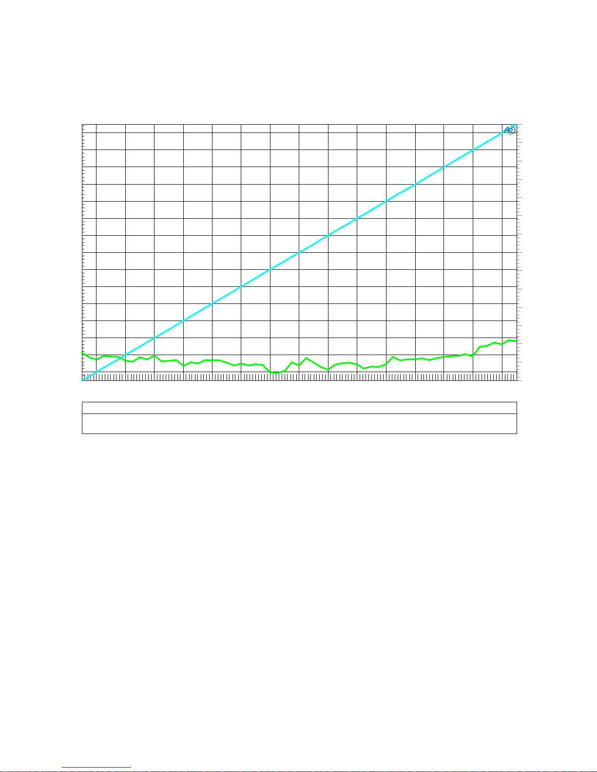
Graph 1 - Stepped Gain Control - THD vs. Gain (-15 dB to +15 dB)
The relay-controlled stepped gain controls are a key feature of the HPA4. The headphone and line
outputs have fully-independent controls. These stepped gain controls are designed to provide
volume control over a wide operating range without adding any significant noise or distortion.
This plot shows that the stepped gain control produces almost no measureable THD. Over a range
of -15 dB to +15 dB, the THD is between -120 dB (0.0001%) and -140 dB (0.00001%) and is near
the measurement limits of the AP2722 test system! This measurement includes the balanced input
and output buffers. This is a virtually distortion-free signal path with gain control.
Notes:
• The cyan curve shows the gain and uses the left-hand (dBr A) scale to show the gain in dB.
This scale is dB relative to the input level. The input level was 10 dBu throughout the test.
• The green curve shows the THD using a 1 kHz test tone. The THD is plotted in dB relative to
the output level and uses the right-hand (dB) scale. The output level was adjusted from -5
dB to +25 dBu using the stepped attenuator.
• Balanced inputs to balanced outputs.
Instruction Manual for HPA4 with 1.0.X Firmware – REV B Page 32
Page 33
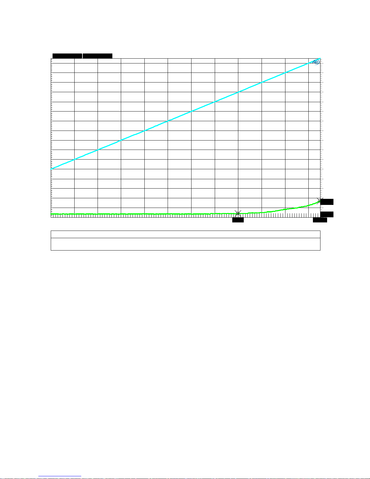
Graph 2 - Stepped Gain Control - Output Noise vs. Gain Setting
Audi o Precision
07/17/18 10:41:20
Attenuator_SNR.at27
ColorSweep Trace Line Style
Thick Data Axis Comment Cursor1
Cursor2
1
1 Cya n Solid
4 Anlr. Level A
Left Gain -20.070 dBr A
+14.947 dBr A
1
2 Green Solid
4 Anlr.Am pl Right A-Weighted Output Noise
*-146.039 dBr *-133.045 dBr
-150
+10
-140
-130
-120
-110
-100
-90
-80
-70
-60
-50
-40
-30
-20
-10
+0
-146.039
-133.045
d
B
r
B
-150
+10
-140
-130
-120
-110
-100
-90
-80
-70
-60
-50
-40
-30
-20
-10
+0
d
B
r
A
-100
+10
-90
-80
-70
-60
-50
-40
-30
-20
-10
+0
-20.07 +14.947
dBr A
dx=+35.017 dB
dy=-12.994 dB
The stepped gain control has a gain range of -112.5 to +15 dB in 0.5 dB steps. This plot shows the
A-weighted output noise over a gain range of -100 dB to + 15 dB. The A-weighted output noise is
plotted relative to the maximum balanced output level of 28 dBu. The signal to noise ratio at any
gain setting is the difference between the two curves. At maximum gain, the SNR is 15 dB - (-133
db) = 148 dB. At a gain of -20 dB, the SNR is -20 dB - (-146 dB) = 126 dB. This test demonstrates
the wide operating range of the fully-balanced low-impedance stepped gain controls.
Below a gain of -20 dB, the noise is determined by the thermal noise (Johnson noise) produced by
the resistors in the stepped attenuator. Ea ch side of the balanced attenuator has an impedance of
just 1210 Ohms. This means that the balanced output impedance of the attenuator is 2420 Ohms.
This resistance determines the output noise of the balanced attenuators. At any gain less than -20
dB, the A-weighted noise floor of the stepped gain control in combination with the balanced output
buffers is -146.5 dB relative to +28 dBu. In other words, the A-weighted output noise is -118.5
dBu. This is approximately equivalent to the thermal noise produced by a single 2.5 kOhm resistor.
This shows that the active balanced output buffers d o not add any significant noise to the stepped
gain control. The active output buffers are important because they provide low impedance drive to
downstream devices (such as power amplifiers and the internal THX-888 headphone amplifier).
Instruction Manual for HPA4 with 1.0.X Firmware – REV B Page 33
Page 34
Audi o Precision
07/16/18 09:26:27
THDvsPowerl_BAL_IN_HPA_Out_16_Ohms.at27
ColorSweep Trace
Line Style Thick Data
Axis Comment
1
1 Green Solid
4
Distortion.Ch.1 Harm Sum1 Ratio Left
-130
-100
-128
-126
-124
-122
-120
-118
-116
-114
-112
-110
-108
-106
-104
-102
d
B
0
6 500m
1
1.5 2 2.5 3 3.5
4
4.5 5
5.5
W
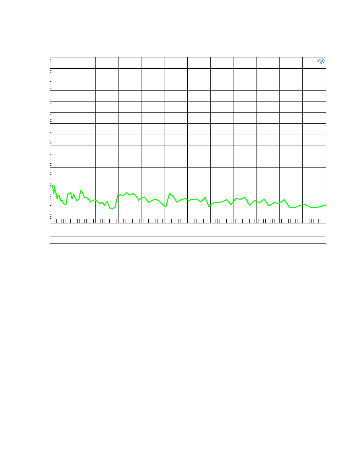
Graph 3 - THD vs. Output Power - Headphone Amplifier - 0 to 6 W into 16-Ohms
The THX-888 headphone amplifier is designed to drive heavy loads at high levels without an
increase in THD. It is also virtually distortion-free at low signal levels and/or light loads.
This output power sweep shows that THD does not increase with output power. The THX-888
headphone amplifier stays extremely clean as the output power is swept from 60 mWatts to 6
Watts. Over this 100:1 range of power, the THD is virtually unchanged! The THD measures better
than about -125 dB (0.000056%) over this wide range of output power into a 16-Ohm load. At the
maximum rated output power or 6 Watts, THD measures about -127 dB (0.00004%).
This test demonstrates the effectiveness of the THX AAA™ technology in the THX-888 amplifier.
Notes:
• The scale on the left is dB THD relative to the output level.
• The test tone is 1 kHz. The test tone level was varied to sweep the output power from 0.06
Watts to 6 Watts.
• Balanced inputs to headphone outputs, volume control set at 0 dB.
Instruction Manual for HPA4 with 1.0.X Firmware – REV B Page 34
Page 35
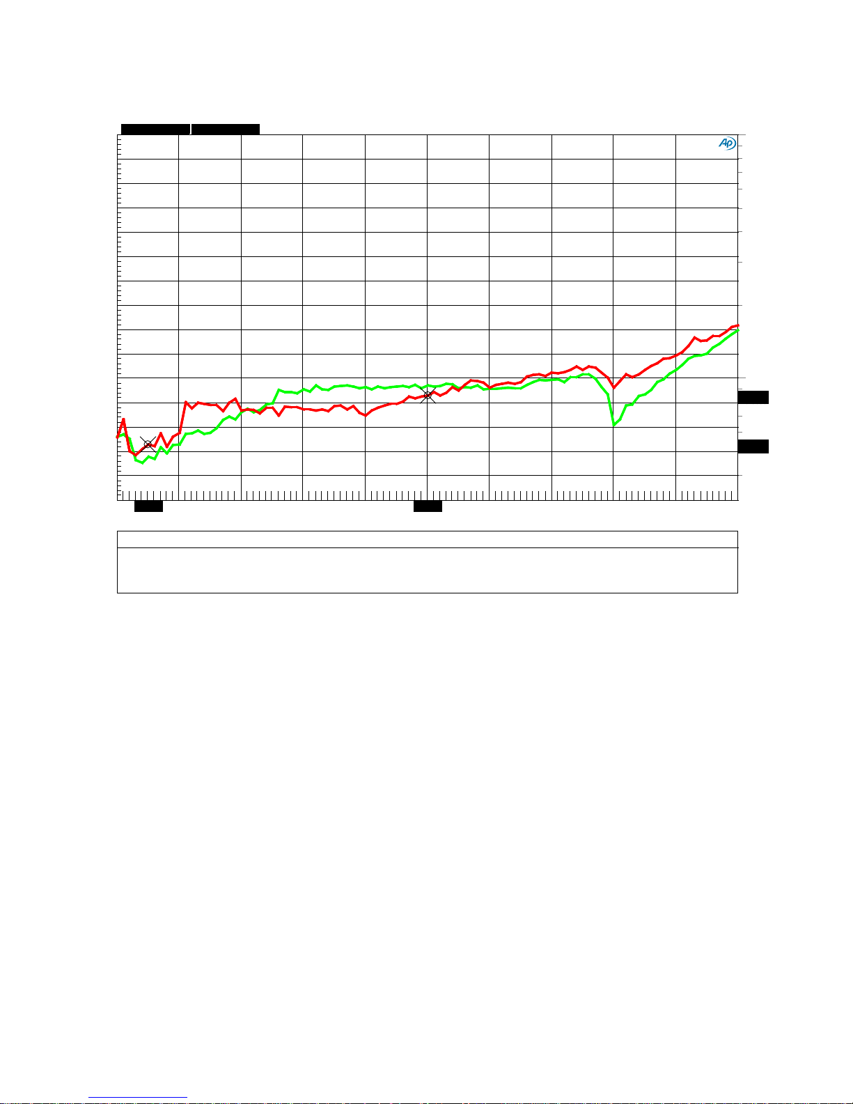
Audi o Precision
07/16/18 12:27:53
THDvsFreq_BAL_IN_HPA_Out_16_Ohms_1Watt.at27
ColorSweep
Trace Line Style Thick
Data
Axis Comment
Source 2 Cursor1 Curs or2
1 2
Green Solid 4
Distortion.Ch.1 Harm Sum1 Ratio Left
L dB : 7.00000 =Swr.Ch. A Input -126.430 dB -120.588 dB
1 3
Green Solid 4 Distortion.Ch.1 Har m Sum1 Ratio
Right L % : 7.00000 =S wr .Ch. A Input
0.00005 % 0.00009 %
2 2 Red Solid
4 Distortion.Ch.1 Har m Sum1 Ratio Left
R dB : 8.00000 = S wr . Ch. A Input -125.405 dB - 121.412 dB
2
3 Red
Solid 4
Distortion.Ch.1 Harm Sum1 Ratio Right
R % : 8.00000 =Swr. Ch. A Input
*0.00005 % *0.00008 %
0.00004
0.001
0.00005
0.00006
0.00007
0.00008
0.00009
0.0001
0.0002
0.0003
0.0004
0.0005
0.0006
0.0007
0.0008
0.0009
0.00005
0.00008
%
-130
-100
-128
-126
-124
-122
-120
-118
-116
-114
-112
-110
-108
-106
-104
-102
d
B
2k
20k 4k 6k 8k
10k
12k 14k
16k
18k
1.019k
10.01k
Hz
TTTT
dx=8.99100 kHz
dy=0.00003 %
Graph 4 - THD vs. Output Frequency - Headphone Amplifier - 20 Hz to 20 kHz Sweep
This frequency sweep shows that the THD remains extremely low when the frequency increases.
The THX-888 headphone amplifier delivered this performance while driving a 16-Ohm load.
Notes:
• The scale on the left is dB THD relative to the output level.
• The output level is 1 Watt into 16-Ohms (4 Vrms, 14.3 dBu).
• The THD measurement bandwidth is 48 kHz.
• The test tone is swept from 20 Hz to 20 kHz.
• Balanced inputs to headphone outputs, volume control set at 0 dB.
Instruction Manual for HPA4 with 1.0.X Firmware – REV B Page 35
Page 36
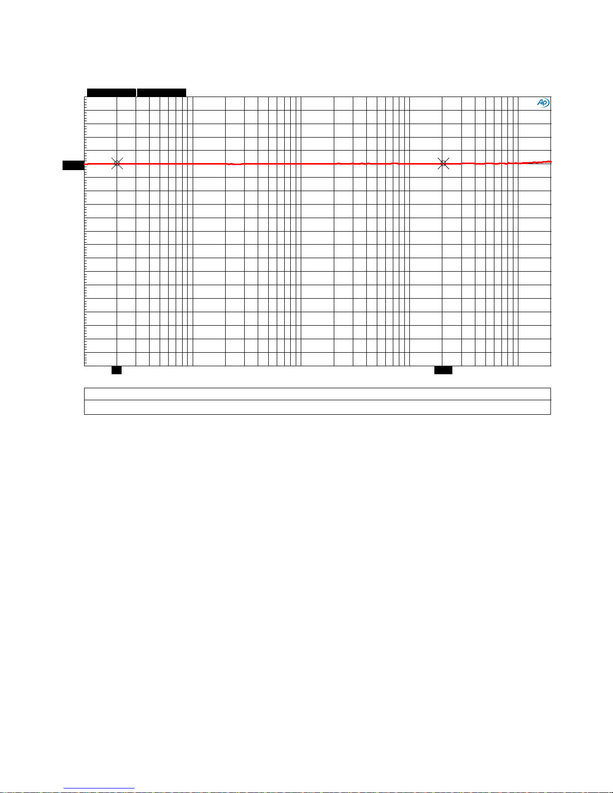
Graph 5 - Frequenc y Respo nse - Line Amplifier
Audi o Precision
07/16/18 09:46:56
Freq_Resp_Bal_Bal.at27
ColorSweep
Trace
Line Style Thick
Data Axis Comment
Cursor1 Cursor2
1
1 Red Solid
4 Anlr. Level A Left Line Out
*+0.003 dBr *+0.003 dBr
-3
+1
-2.8
-2.6
-2.4
-2.2
-2
-1.8
-1.6
-1.4
-1.2
-1
-0.8
-0.6
-0.4
-0.2
+0
+0.2
+0.4
+0.6
+0.8
+0.003+0.003
d
B
r
A
10
200k
20 50
100
200
500
1k
2k
5k
10k 20k 50k 100k
20.5k
20
Hz
dx=-20.480 kHz
dy=+0.000 dB
The -3 dB frequency response of the line amplifier extends from about 0.1 Hz to 500 kHz. This is
well beyond the 10 Hz to 200 kHz range of our AP2722 measurement system. Over our 10 Hz to
200 kHz measurement range, the frequency response is perfectly flat.
The primary advantage of this wide frequency response is that it delivers a very precise phase
response. Low bass is delivered with precise timing relative to the highest audible frequencies (and
everything in between). Furthermore, the extreme bandwidth keeps the L/R differential phase
nearly perfect. The result is an unrivaled stereo image with accurate placement of musical voices
within a 3D sound stage.
Notes:
• The scale on the left (dBr A) is dB relative to the output level at 1 kHz. The test used a
0-dBu test tone. The small +/- 0.003 dB random variations shown are due to the
measurement limitations of the AP2722.
• Balanced inputs to balanced line outputs, volume contro l set at 0 dB.
Instruction Manual for HPA4 with 1.0.X Firmware – REV B Page 36
Page 37
Audi o Precision
07/16/18 11:52:07
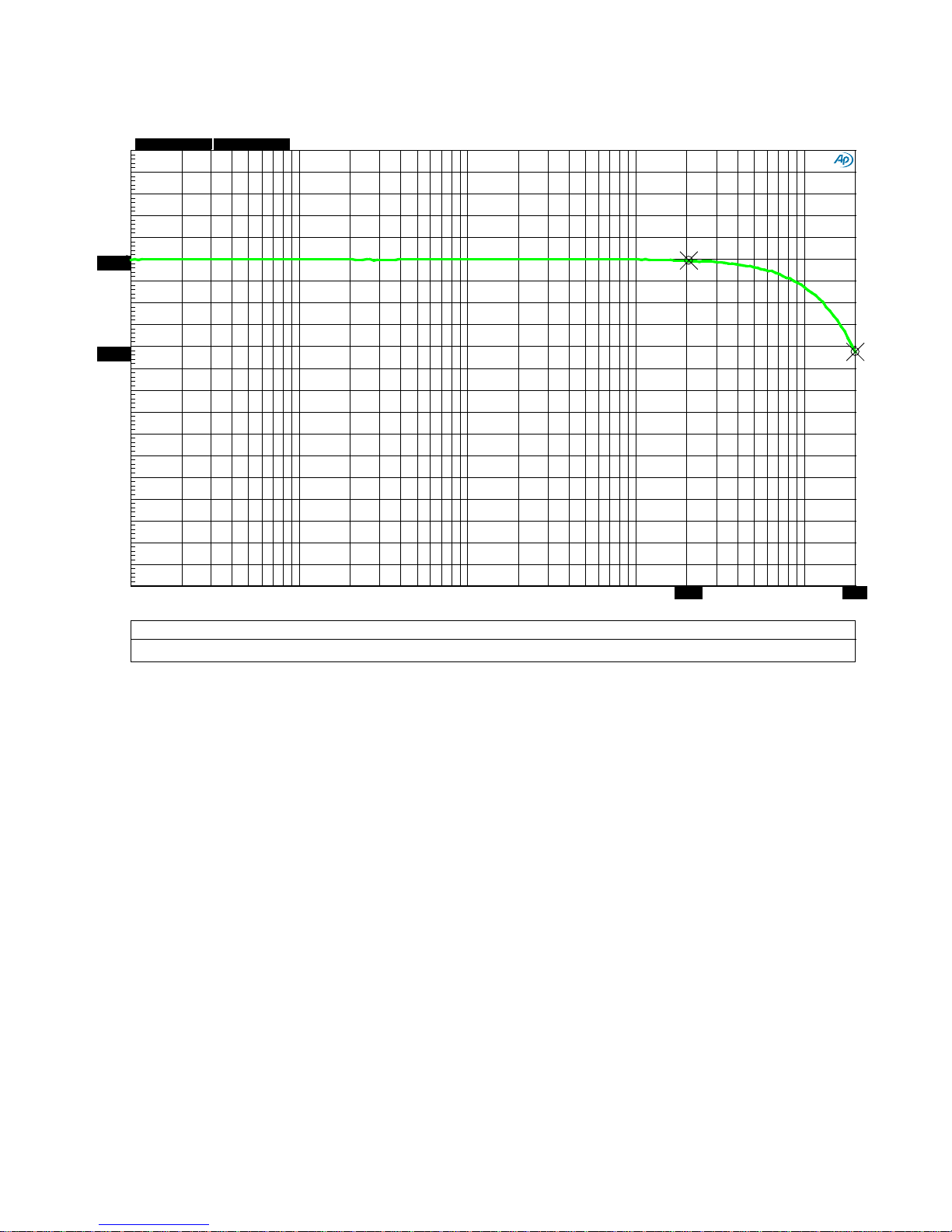
Freq_Resp_Bal_HPA_300-Ohms.at27
ColorSweep Trace
Line Style Thick Data Axis
Comment Cursor1
Cursor2
1 1
Green Solid
4 Anlr.Level A
Left HP Out into 300 O hms
*-0.014 dBr *-0.850 dBr
-3
+1
-2.8
-2.6
-2.4
-2.2
-2
-1.8
-1.6
-1.4
-1.2
-1
-0.8
-0.6
-0.4
-0.2
+0
+0.2
+0.4
+0.6
+0.8
-0.014
-0.85
d
B
r
A
10
200k 20
50
100 200 500 1k 2k 5k
10k
20k 50k
100k
20.5k
200k
Hz
dx=179.500 kHz
dy=-0.836 dB
Graph 6 - Frequenc y Respo nse - Headphone Amplifier - 300-Ohm Load
This plot is included to show that the frequency response of the headphone amplifier changes very
little when the load impedance changes. The 16-Ohm re sponse (shown in Graph 7) is nearly
identical to the 300-Ohm response shown in this graph.
Notes:
• The scale on the left (dBr A) is dB relative to the output level at 1 kHz. The test used a
0-dBu test tone.
• Balanced inputs to headphone outputs, volume control set at 0 dB.
Instruction Manual for HPA4 with 1.0.X Firmware – REV B Page 37
Page 38
Audi o Precision
07/16/18 11:55:30
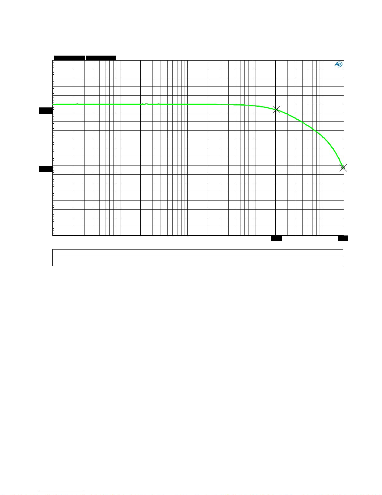
Freq_Resp_Bal_HPA_16-Ohms.at27
ColorSweep Trace
Line Style Thick Data Axis
Comment Cursor1
Cursor2
1 1
Green Solid
4 Anlr.Level A
Left HP Out into 16 O hms
*-0.125 dBr *-1.453 dBr
-3
+1
-2.8
-2.6
-2.4
-2.2
-2
-1.8
-1.6
-1.4
-1.2
-1
-0.8
-0.6
-0.4
-0.2
+0
+0.2
+0.4
+0.6
+0.8
-0.125
-1.453
d
B
r
A
10
200k 20
50
100 200 500 1k 2k 5k
10k
20k 50k
100k
20.5k
200k
Hz
dx=179.500 kHz
dy=-1.328 dB
Graph 7 - Frequenc y Respo nse - Headphone Amplifier - 16-Ohm L oad
The -3 dB frequency response of the headphone amplifier extends well beyond the 10 Hz to 200
kHz range of our AP2722 measurement system. The response is -0.125 dB at 20 kHz and -1.45 dB
at 200 kHz when driving a heavy 16-Ohm load. Compare this to Graph 6 (frequency response into
300 Ohms). The difference in frequency response due to the heavy 16-Ohm loading is minimal. The
difference due to loading is only 0.1 dB at 20 kHz and 0.6 dB at 200 kHz.
Notes:
• The scale on the left (dBr A) is dB relative to the output level at 1 kHz. The test used a
0-dBu test tone.
• Balanced inputs to headphone outputs, volume control set at 0 dB.
Instruction Manual for HPA4 with 1.0.X Firmware – REV B Page 38
Page 39
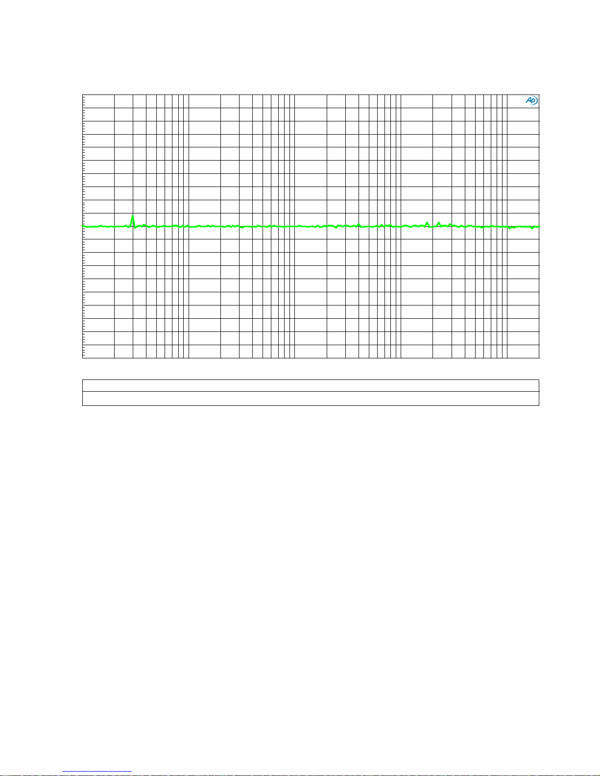
Graph 8 - Differential P hase - Line Amplifier
Audi o Precision
07/13/18 12:26:48
Differential_Phase_Bal_Bal.at27
ColorSweep Trace Line Style Thick Data Axis Comment
1 1 Green Solid 4 Anlr.Phase!Delta Left
-1
+1
-0.9
-0.8
-0.7
-0.6
-0.5
-0.4
-0.3
-0.2
-0.1
+0
+0.1
+0.2
+0.3
+0.4
+0.5
+0.6
+0.7
+0.8
+0.9
d
e
g
10 200k
20 50 100
200 500
1k 2k 5k 10k 20k
50k
100k
Hz
This plot shows the differential phase between the left and right channels. The extended 0.1 Hz to
500 kHz frequency resp onse keeps the phase response of the two channels well matched over the
audio band. This plot shows that the differential phase is virtually perfect! Notice that the scale is
highly expanded (+/- 1 degree). The slight bumps in the curve are due to the measurement limits
of the AP2722 test station. This L/R phase matching is much be tter than the L/R phase matching in
the AP2722 test station. To make this measurement, we had to create a correction curve for the
AP2722. The correction curve removes the phase errors produced by the test equipment, allowing
measurement of the line amplifier.
Notes:
• The vertical scale is the phase difference between the left and right channels.
• Balanced inputs to balanced outputs, volume control set at 0 dB.
Instruction Manual for HPA4 with 1.0.X Firmware – REV B Page 39
Page 40
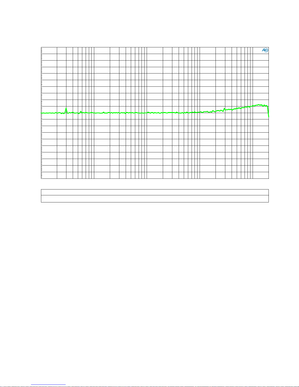
Graph 9 - Differential P hase - Headphone Amp lifier - 300-Ohm Load
Audi o Precision
07/13/18 12:30:10
Differential_Phase_Bal_HP_300_Ohms.at27
ColorSweep
Trace
Line Style Thick
Data Axis Comment
1 1
Green Solid 4 Anlr.Phase!Delta Left
-1
+1
-0.9
-0.8
-0.7
-0.6
-0.5
-0.4
-0.3
-0.2
-0.1
+0
+0.1
+0.2
+0.3
+0.4
+0.5
+0.6
+0.7
+0.8
+0.9
d
e
g
10
200k
20 50
100
200
500
1k
2k
5k
10k 20k 50k 100k
Hz
This plot shows the differential phase betwee n the le ft and right headphone channels. The
extended frequency response keeps the phase response of the two channels well matched over the
audio band. This plot shows that the differential phase is virtually perfect! At 200 kHz, the
differential phase error is only about 0.1 degree.
Notes:
• The vertical scale is the phase difference between the left and right channels.
• Balanced inputs to headphone outputs, volume control set at 0 dB.
Instruction Manual for HPA4 with 1.0.X Firmware – REV B Page 40
Page 41
Audi o Precision
07/13/18 15:49:14
FFT_Idle_Unity_Gain_Bal_Bal.at27
ColorSweep
Trace Line Style
Thick Data Axis
Comment Source 2
1
2 Green
Solid 4 Fft.Ch.1 Ampl Left
Left Line O utput : 1.00000 =S wr .Ch. A Input
1
3
Green Solid 4 Fft.Ch.1 Ampl Right
: 1.00000 =S wr .Ch. A Input
2
2 Red Solid 4 Fft.Ch.1 Ampl Left Right Line Output
: 2.00000 =S wr .Ch. A Input
2
3
Red
Solid 4
Fft.Ch.1 Ampl Right
: 2.00000 =S wr .Ch. A Input
3
2 Yellow
Solid 4
Fft.Ch.1 Ampl Left Mono Line Out put
: 3.00000 =S wr .Ch. A Input
3 3
Yellow Solid 4
Fft.Ch.1 Ampl Right : 3. 00000 = S wr.Ch. A Input
-180
+0
-170
-160
-150
-140
-130
-120
-110
-100
-90
-80
-70
-60
-50
-40
-30
-20
-10
d
B
r
B
-190
+0
-180
-170
-160
-150
-140
-130
-120
-110
-100
-90
-80
-70
-60
-50
-40
-30
-20
-10
d
B
r
A
2.5k 47.5k 5k 7.5k 10k 12.5k 15k 17.5k 20k 22.5k 25k
27.5k
30k
32.5k
35k 37.5k 40k 42.5k 45k
Hz
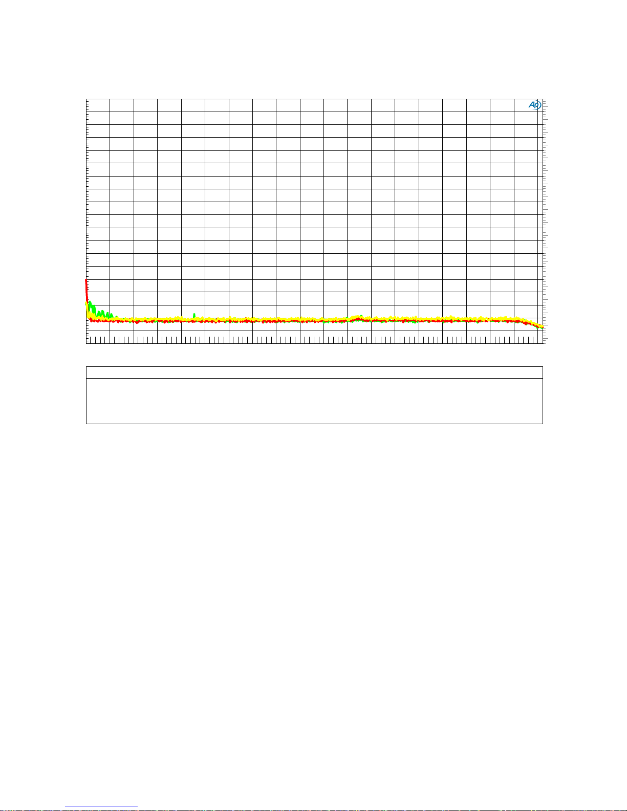
Graph 10 - FFT Idle Channel Noise - Balanced In to Balanced Out
The HPA4 is an exceptionally quiet line amplifier. This allows it to be inserted between a
Benchmark DAC3 and an AHB2 power amplifier without degrading the noise performance of the
system. This same line stage is used in front of the THX-888 headphone amplifier. The line stage
provides volume control without degrading the perform a nce of the headphone amplifier.
Notes:
• The scale on the left (dBr A) is dB relative to +28 dBu. This is the maximum input and
output level supported by the HPA4 line stage.
• The scale on the right (dBr B) is dB relative to +22 dBu. This is the input level required to
drive an external AHB2 power amplifier to full output power. It is also the level required to
drive the internal THX-888 to full output power.
• Balanced inputs to balanced line outputs, volume control set at 0 dB.
Instruction Manual for HPA4 with 1.0.X Firmware – REV B Page 41
Page 42
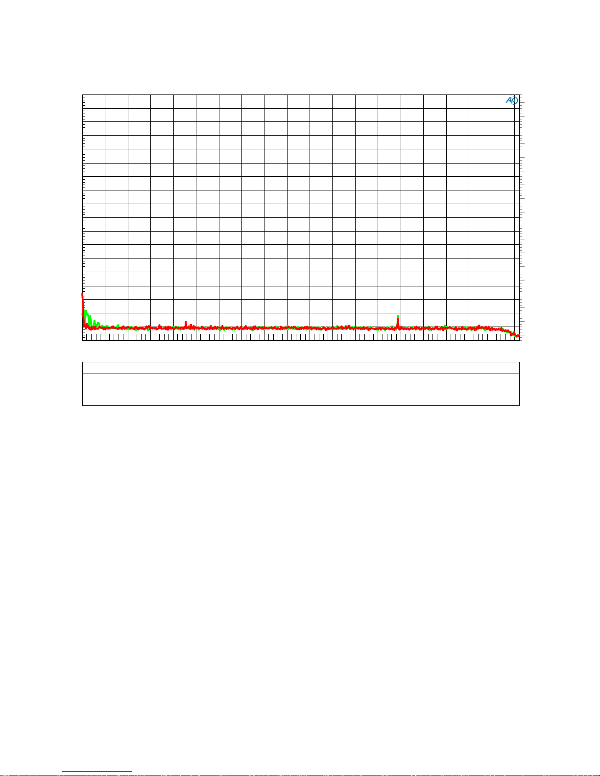
Graph 11 - FFT Idle Channel Noise - Balanced In to Headphone Out
Audi o Precision
07/13/18 10:03:10
FFT_Idle_Unity_Gain_Bal_HPA.at27
Color
Sweep
Trace Line Style Thick
Data Axis Comment
Source 2
1 2 Green Solid 4
Fft.Ch.1 Ampl Left Left HP Output : 7.00000 =S wr .Ch. A Input
1
3 Green
Solid 4
Fft.Ch.1 Ampl Right
: 7.00000 =S wr .Ch. A Input
2 2
Red Solid 4
Fft.Ch.1 Ampl Left Right HP Output
: 8.00000 =S wr .Ch. A Input
2
3 Red Solid
4 Fft.Ch.1 Ampl Right
: 8.00000 =S wr .Ch. A Input
-170
+0
-160
-150
-140
-130
-120
-110
-100
-90
-80
-70
-60
-50
-40
-30
-20
-10
d
B
r
B
-180
+0
-170
-160
-150
-140
-130
-120
-110
-100
-90
-80
-70
-60
-50
-40
-30
-20
-10
d
B
r
A
2.5k 47.5k 5k 7.5k
10k
12.5k 15k
17.5k 20k
22.5k 25k
27.5k
30k 32.5k
35k 37.5k 40k 42.5k 45k
Hz
This graph shows the noise performance of the HPA4 from the balanced inputs to the output of the
THX-888 headphone amplifier. This extraordinary performance keeps noise at inaudible levels,
even when using high-efficiency headphones.
Notes:
• The scale on the left (dBr A) is dB relative to +28 dBu. This is the maximum input and
output level supported by the HPA4 line stage.
• The scale on the right (dBr B) is dB relative to +22 dBu. This is the input level required to
drive an external AHB2 power amplifier to full output power. It is also the level required to
drive the internal THX-888 to full output power.
• Balanced inputs to headphone outputs, volume control set at 0 dB.
Instruction Manual for HPA4 with 1.0.X Firmware – REV B Page 42
Page 43
Audi o Precision
07/13/18 10:02:46
FFT_Idle_Unity_Gain_Bal_Bal_Low_Freq.at27
ColorSweep
Trace Line Style
Thick Data Axis
Comment Source 2
Cursor1 Cursor2
1 2
Green Solid
4 Fft.Ch.1 Ampl Left
Left Line O ut : 1.00000 =Swr. Ch. A Input
-150.645 dBr A -150.464 dBr A
1
3
Green Solid 4 Fft.Ch.1 Ampl Right
: 1.00000 =S wr .Ch. A Input *-144.645 dBr
*-144.464 dBr
2 2 Red Solid 4
Fft.Ch.1 Ampl Left Right Line Out : 2.00000 =Swr.Ch. A Input -149.889 dBr A
-149.685 dBr A
2
3
Red Solid
4
Fft.Ch.1 Ampl Right
: 2.00000 =S wr .Ch. A Input -143.889 dBr B -143.685 dBr B
3
2 Yellow Solid
4 Fft.Ch.1 Ampl
Left Mono Line Out
: 3.00000 =S wr .Ch. A Input -150.113 dBr A -150.050 dBr A
3 3 Yellow
Solid 4 Fft.Ch.1 Ampl Right
: 3.00000 =S wr .Ch. A Input -144.113 dBr B
-144.050 dBr B
-180
+0
-170
-160
-150
-140
-130
-120
-110
-100
-90
-80
-70
-60
-50
-40
-30
-20
-10
-144.645-144.464
d
B
r
B
-190
+0
-180
-170
-160
-150
-140
-130
-120
-110
-100
-90
-80
-70
-60
-50
-40
-30
-20
-10
d
B
r
A
20 400 40 60 80 100 120 140 160 180 200 220
240
260
280
300 320 340 360 380
180.196 300.02
Hz
dx=119.824 Hz
dy=+0.182 dB
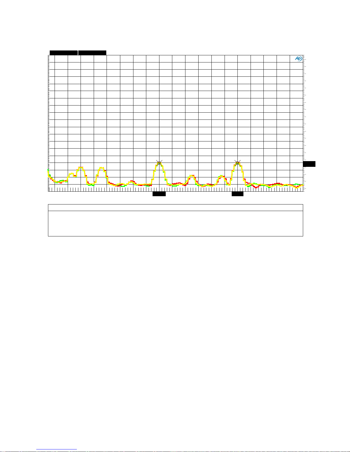
Graph 12 - AC Line-Related Hum - Line Amplifier
This FFT plot shows that AC line-related hum is 150 dB below the maximum output level of +28
dBu (use the left-hand dBr A scale)! The AC line frequency was 60 Hz in this test.
This plot also shows that AC line-related hum is 144 dB below the maximum input level of the
internal THX-888 and an externally connected AHB2 power amplifier. These levels are so low that
they will not impact the system SNR through the internal THX-888 or an external AHB2.
Notes:
• The scale on the left (dBr A) is dB relative to +28 dBu. This is the maximum input and
output level supported by the HPA4 line stage.
• The scale on the right (dBr B) is dB relative to +22 dBu. This is the input level required to
drive an external AHB2 power amplifier to full output power. It is also the level required to
drive the internal THX-888 to full output power.
• Balanced inputs to balanced line outputs, volume control set at 0 dB.
Instruction Manual for HPA4 with 1.0.X Firmware – REV B Page 43
Page 44
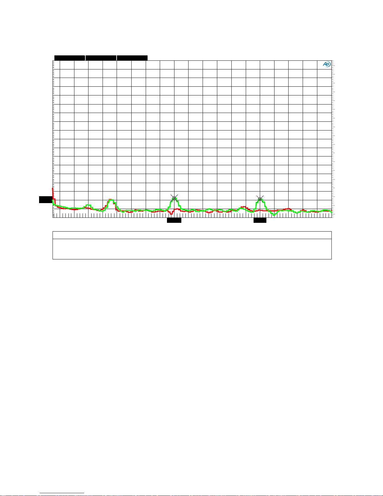
Graph 13 - AC Line-Related Hum - Headphone Output
Audi o Precision
07/13/18 16:47:12
FFT_Idle_Unity_Gain_Bal_HPA_Low_Freq.at27
Color
Sweep
Trace Line Style Thick
Data Axis Comment
Source 2 Cursor1
Cursor2
1 2 Green Solid
4 Fft.Ch.1 Ampl Left Left HP Output : 7.00000 =Swr. Ch. A I nput
*-157.763 dBr *-159.010 dBr
1 3
Green
Solid 4
Fft.Ch.1 Ampl Right
: 7.00000 =S wr .Ch. A Input -151.763 dBr B -153.010 dBr B
2
2 Red
Solid 4
Fft.Ch.1 Ampl Left Right HP Output
: 8.00000 =S wr .Ch. A Input -170.357 dBr A -171.347 dBr A
2 3
Red Solid 4
Fft.Ch.1 Ampl Right : 8. 00000 = S wr.Ch. A Input
-164.357 dBr B -165.347 dBr B
-170
+0
-160
-150
-140
-130
-120
-110
-100
-90
-80
-70
-60
-50
-40
-30
-20
-10
d
B
r
B
-180
+0
-170
-160
-150
-140
-130
-120
-110
-100
-90
-80
-70
-60
-50
-40
-30
-20
-10
-157.763
-159.01
d
B
r
A
20 400
40
60
80 100
120 140
160 180
200
220 240
260 280
300 320 340 360 380
180.196 300.02
Hz
dx=119.824 Hz
dy=-1.247 dB
7.00000
This FFT plot shows that AC line-related hum is at least 152 dB below the THX-888 headphone
amplifier's maximum output level of +22 dBu (use the r ight-hand dBr B scale)!
Notes:
• The scale on the left (dBr A) is dB relative to +28 dBu. This is the maximum input and
output level supported by the HPA4 line stage.
• The scale on the right (dBr B) is dB relative to +22 dBu. This is the input level required to
drive an external AHB2 power amplifier to full output power. It is also the level required to
drive the internal THX-888 to full output power.
• Balanced inputs to headphone outputs, volume control set at 0 dB.
Instruction Manual for HPA4 with 1.0.X Firmware – REV B Page 44
Page 45
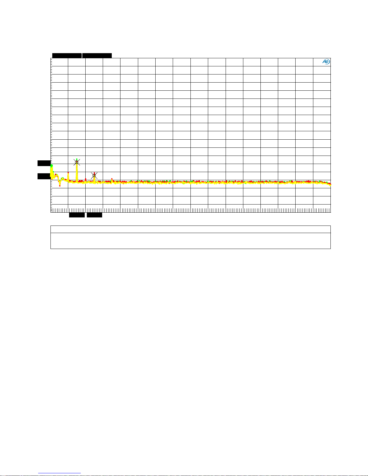
Graph 14 - FFT 1 kHz Tone at 22 dBu - Line Amplifier - Balanced to Balanced
Audi o Precision
07/13/18 10:57:04
FFT_1kHz_Bal_Bal.at27
ColorSweep
Trace Line Style Thick Data Axi s
Comment
Source 2 Cursor1
Cursor2
1
2
Green
Solid 4
Fft.Ch.1 Ampl Left Left Line Out
: 1.00000 =S wr .Ch. A Input -124.094 dBr B
-146.609 dBr B
2 2
Red Solid 4
Fft.Ch.1 Ampl Left Right Line Out
: 2.00000 =S wr .Ch. A Input -126.729 dBr B
-141.285 dBr B
3
2 Yellow Solid 4
Fft.Ch.1 Ampl Left Mono Line Out
: 3.00000 =S wr .Ch. A Input *-128.219 dBr *-144.566 dBr
-190
+0
-180
-170
-160
-150
-140
-130
-120
-110
-100
-90
-80
-70
-60
-50
-40
-30
-20
-10
-128.219
-144.566
d
B
r
B
2k 32k
4k 6k 8k 10k
12k 14k
16k
18k 20k
22k
24k 26k
28k 30k
3.01493k
5.01822k
Hz
dx=2.00329 kHz
dy=-16.347 dB
This plot shows that the THD produced by the line amplifier is extremely low, even when delivering
a very high 22 dBu output. The third harmonic measures better than -124 dB (0.00006%) on all
balanced outputs! The 5th harmonic measures better than -141 dB (0.000009%) on all balanced
outputs!
Notes:
• The scale on the left (dBr B) is dB relative to +22 dBu. This is the signal level required to
drive an external AHB2 power amplifier to full output power. It is also the level required to
drive the internal THX-888 to full output power. It is also the level of the test tone.
• Balanced inputs to balanced line outputs, volume control set at 0 dB.
• The 1 kHz fundamental has b een removed using a notch filter . This filter increases the
resolution of the AP2722 test system.
Instruction Manual for HPA4 with 1.0.X Firmware – REV B Page 45
Page 46
Audi o Precision
07/13/18 11:45:55
FFT_1kHz_Ubal_Ubal.at27
ColorSweep Trace Line Style
Thick Data Axis Comment Source 2
Cursor1 Cursor2
1
2 Green
Solid 4
Fft.Ch.1 Ampl Left L RCA Out
: 5.00000 =S wr .Ch. A Input *-119.172 dBr *-118.128 dBr
2 2
Red Solid 4
Fft.Ch.1 Ampl Left R RCA Out : 6.00000 =Swr.Ch. A Input
-118.981 dBr B -118.977 dBr B
-190
+0
-180
-170
-160
-150
-140
-130
-120
-110
-100
-90
-80
-70
-60
-50
-40
-30
-20
-10
-119.172
-118.128
d
B
r
B
2k
32k
4k
6k
8k
10k
12k
14k
16k
18k
20k
22k
24k
26k
28k
30k
2.01329k3.01493k
Hz
dx=1.00164 kHz
dy=+1.044 dB
Graph 15 - FFT 1 kHz Tone at 1.6 Vrms - Li ne Amplifier - Unbalanced to Unbalanced
This plot shows the performance of the unba lanced inputs and outputs. The input level is 1.6 Vrms
which is the level required to produce 22 dBu on the balanced o utputs. This level was selected to
match the operating point used in Graph 14.
If you compare Graph 6 (unbalanced) to Graph 5 (balanced) you can see that the unbalanced
inputs and outputs perform very well in terms of THD. However, the SNR is slightly reduced due to
the much lower signal levels used with unbalanced interconnects.
Notes:
• The scale on the left (dBr B) is dB relative to 1.6 Vrms. It is also the level of the test tone.
• Unbalanced inputs to unbalanced line outputs, volume control set at 0 dB.
• The 1 kHz fundamental has b een removed using a notch filter . This filter increases the
resolution of the AP2722 test system.
Instruction Manual for HPA4 with 1.0.X Firmware – REV B Page 46
Page 47
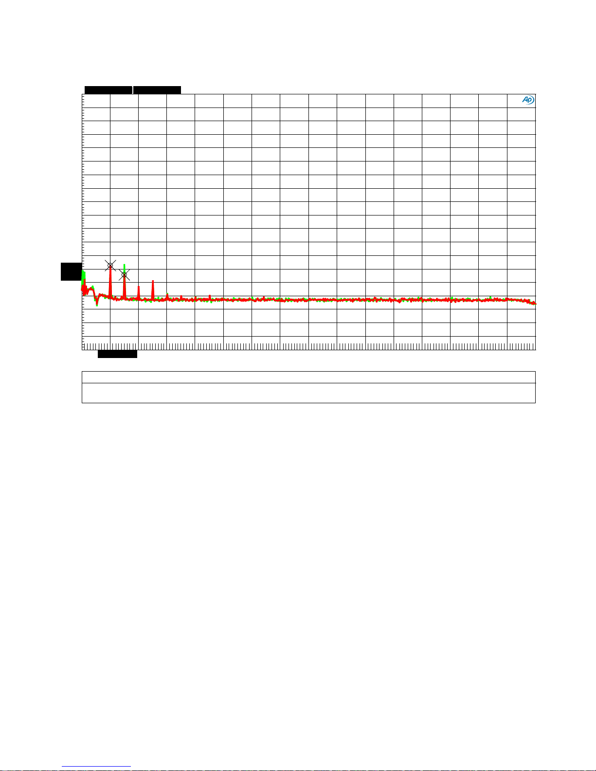
Audi o Precision
07/13/18 10:40:31
FFT_1kHz_Bal_HPA_16_Ohms.at27
ColorSweep Trace Line Style
Thick Data Axis Comment Source 2
Cursor1 Cursor2
1
2 Green
Solid 4
Fft.Ch.1 Ampl Left L HP Out into 16 O hms
: 7.00000 =S wr .Ch. A Input -130.396 dBr B -126.744 dBr B
2 2
Red Solid 4
Fft.Ch.1 Ampl Left R HP Out into 16 O hms : 8.00000 =S wr .Ch. A Input
*-127.591 dBr *-134.156 dBr
-190
+0
-180
-170
-160
-150
-140
-130
-120
-110
-100
-90
-80
-70
-60
-50
-40
-30
-20
-10
-127.591
-134.156
d
B
r
B
2k
32k
4k
6k
8k
10k
12k
14k
16k
18k
20k
22k
24k
26k
28k
30k
2.01329k3.01493k
Hz
dx=1.00164 kHz
dy=-6.565 dB
Graph 16 - FFT 1 kHz Tone at 22 dBu - Hea dphone Amplifier - 6 W into 16-Ohms
This plot shows that the THD produced by the THX-888 headphone amplifier is ex tremely low,
even when delivering a very high 22 dBu output into a low-impedance 16-Ohms load. The output
power is 6 Watts per channel. The 2nd harmonic measures better than -127.5 dB (0.00004%)
under full rated load! The 3rd harmonic measures better than -126.5 dB (0.000005%)! This test
demonstrates the effectiveness of the THX AAA™ with feed-forward error correction.
Notes:
• The scale on the left (dBr B) is dB relative to +22 dBu. This is the signal level required to
drive an external AHB2 power amplifier to full output power. It is also the level required to
drive the internal THX-888 to full output power. It is also the level of the test tone.
• Balanced inputs to headphone outputs, volume control set at 0 dB.
• The 1 kHz fundamental has been removed using a notch filter. This filter increases the
resolution of the AP2722 test system.
Instruction Manual for HPA4 with 1.0.X Firmware – REV B Page 47
Page 48
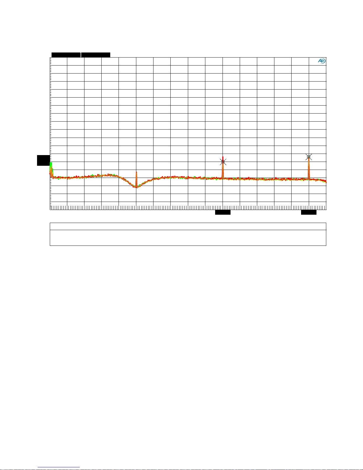
Graph 17 - FFT 10 kHz Tone at 22 dBu - L i ne Amplifier
Audi o Precision
07/13/18 10:59:10
FFT_10kHz_Bal_Bal.at27
ColorSweep
Trace Line Style Thick Data Axi s
Comment
Source 2 Cursor1
Cursor2
1
2
Green
Solid 4
Fft.Ch.1 Ampl Left Left Line Out
: 1.00000 =S wr .Ch. A Input *-130.406 dBr
*-124.343 dBr
2 2
Red Solid 4
Fft.Ch.1 Ampl Left Right Line Out
: 2.00000 =S wr .Ch. A Input -124.132 dBr B
-125.049 dBr B
3
2 Yellow Solid 1
Fft.Ch.1 Ampl Left Mono Line Out
: 3.00000 =S wr .Ch. A Input -130.115 dBr B -124.568 dBr B
-190
+0
-180
-170
-160
-150
-140
-130
-120
-110
-100
-90
-80
-70
-60
-50
-40
-30
-20
-10
-130.406
-124.343
d
B
r
B
2k 32k
4k 6k 8k 10k
12k 14k
16k
18k 20k
22k
24k 26k
28k 30k
20.0429k 29.9967k
Hz
dx=9.95384 kHz
dy=+6.064 dB
This plot shows that the THD produced by the line amplifier is extre mely low, even when delivering
a very high 22 dBu output. The 2nd and 3rd harmonics each measure better than -124 dB
(0.00006%)! This test shows that THD does not increase when reprod ucing high frequencies.
Notes:
• The scale on the left (dBr B) is dB relative to +22 dBu. This is the signal level required to
drive an external AHB2 power amplifier to full output power. It is also the level required to
drive the internal THX-888 to full output power. It is also the level of the test tone.
• Balanced inputs to balanced line outputs, volume control set at 0 dB.
• The 10 kHz fundamental has been removed using a notch filter. This filter increases the
resolution of the AP2722 test system.
Instruction Manual for HPA4 with 1.0.X Firmware – REV B Page 48
Page 49
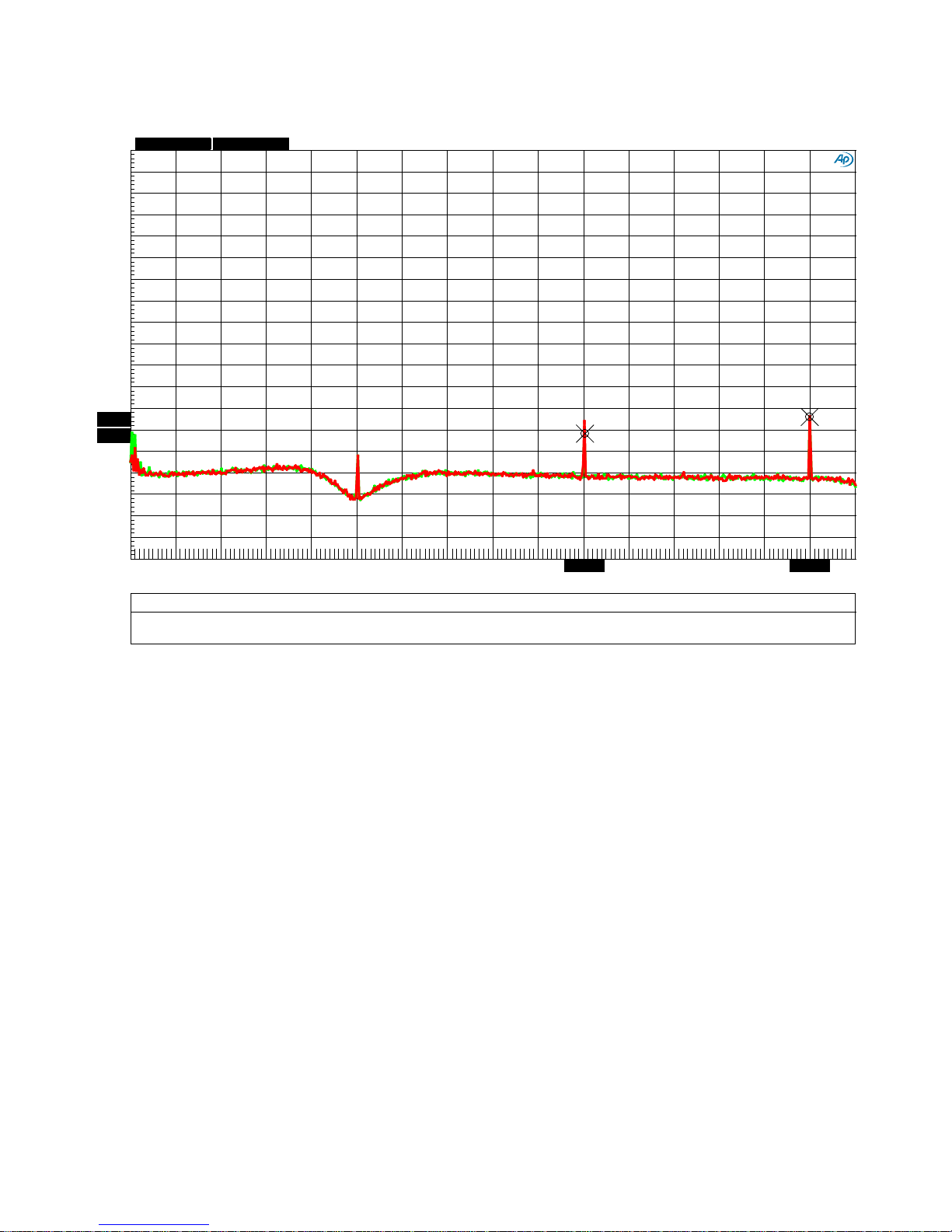
Audi o Precision
07/13/18 11:03:28
FFT_10kHz_Bal_HPA_16_Ohms.at27
ColorSweep Trace Line Style
Thick Data Axis Comment Source 2
Cursor1 Cursor2
1
2 Green
Solid 4
Fft.Ch.1 Ampl Left L HP Out into 16 O hms
: 7.00000 =S wr .Ch. A Input *-131.738 dBr *-123.982 dBr
2 2
Red Solid 4
Fft.Ch.1 Ampl Left R HP Out into 16 O hms : 8.00000 =S wr .Ch. A Input
-125.997 dBr B -123.818 dBr B
-190
+0
-180
-170
-160
-150
-140
-130
-120
-110
-100
-90
-80
-70
-60
-50
-40
-30
-20
-10
-131.738
-123.982
d
B
r
B
2k
32k
4k
6k
8k
10k
12k
14k
16k
18k
20k
22k
24k
26k
28k
30k
20.0429k
29.9967k
Hz
dx=9.95384 kHz
dy=+7.755 dB
Graph 18 - FFT 10 kHz Tone at 22 dBu - Headphone Amplifier - 6 W into 16-Ohms
This plot shows that the THX-888 headphone amplifier stays extremely clean, even when
delivering 6 Watts at 10 kHz! The output level is 22 dBu (9.8 Vrms). The load impedance is 16
Ohms. Under these extreme high slew rate conditions, the 2nd and 3rd harmonics measure better
than about -124 dB (0.00006%) into a difficult 16-Ohm load! This test demonstrates the
effectiveness of the THX AAA™ technology which includes feed-forward error correction.
Notes:
• The scale on the left (dBr B) is dB relative to +22 dBu. This is the signal level required to
drive an external AHB2 power amplifier to full output power. It is also the level required to
drive the internal THX-888 to full output power. It is also the level of the test tone.
• Balanced inputs to headphone outputs, volume control set at 0 dB.
• The 10 kHz fundamental has been removed using a notch filter. This filter increases the
resolution of the AP2722 test system.
Instruction Manual for HPA4 with 1.0.X Firmware – REV B Page 49
Page 50

Specifications
THX-888 Headphone Outputs
Test conditions: 1 kHz test tone, Output Level = +21 dBu, Unity Gain (unless noted)
Number of Headphone Outputs
2
Output Connector - Differential Drive
Gold-Pin Neutrik™ XLR4 - female
Output Connector - Common Ground Return
1/4" Neutrik™ TRS Jack
SNR
135 dB, A-Weighted
131 dB, 20 Hz to 20 kHz
Output Noise
< 2.45 uV, 20 Hz to 20 kHz
Frequency Response
-0.006 dB at 10 Hz
-3 dB at 0.1 Hz and 500 kHz
Output Impedance
Near 0 Ohms
Maximum Output Power and Voltage
6 Watts into 16 Ohms, 9.8 Vrms
440 mW into 300 Ohms, 11.5 Vrms
Maximum Output Current (protection thres hold)
1.5 Amps
Crosstalk, XLR4 Output
-133 dB@1kHz, -115 dB@10kHz
THD, 16-Ohm Load
-125 dB, 0.00006%, 16-Ohm Load
THD+N, 20 kHz BW, 16-Ohm load
-115 dB, 0.00018%
Volume Control Range
Mute, -112 dB to +15 dB in 0.5 dB
steps
Balance Control Range
+/- 6 dB in 0.5 dB steps
Balanced Analog Outputs
Test conditions: 1 kHz test tone, Output Level = +24 dBu, Unity Gain (unless noted)
Number of Balanced Analog Outputs
3 (left, right, mono sum)
Output Connectors
Gold-Pin Neutrik™ XLR - male
SNR
137 dB, A-Weighted
135 dB, 20 Hz to 20 kHz
Output Noise
< 2.1 uV, 20 Hz to 20 kHz
Frequency Response
-0.005 dB at 10 Hz
-3 dB at 0.1 Hz and 500 kHz
Output Impedance
60 Ohms
Maximum Output Level
+28 dBu, 19.5 Vrms
THD
-126 dB, 0.00005%
THD+N, 20 kHz BW
-115 dB, 0.00018%
Volume Control Range (with 0 dBFS digita l in put)
Mute, -112 dB to +15 dB in 0.5 dB
steps
Balance Control Range
+/- 6 dB in 0.5 dB steps
-0.014 dB at 20 kHz
2.6 Watts into 45 Ohms, 10.8 Vrms
640 mW into 200 Ohms, 11.3 Vrms
-0.001 dB at 20 kHz
Instruction Manual for HPA4 with 1.0.X Firmware – REV B Page 50
Page 51

Unbalanced Analog Outputs
Test conditions: 1 kHz test tone, Input Level = 2 Vrms, Unity Gain (unless noted)
Number of Unbalanced Analog Outputs
2 (left, right)
Output Connectors
Gold RCA - female
SNR
116 dB, A-Weighted
108 dB, 20 Hz to 20 kHz
Output Noise
< 8 uV, 20 Hz to 20 kHz
Frequency Response
-0.008 dB at 10 Hz
-0.005 dB at 20 kHz
-3 dB at 0.1 Hz and 500 kHz
Output Impedance
30 Ohms
Maximum Output Level
+12.2 dBu, 3.2 Vrms
Volume Control Range (with 0 dBFS digita l in put)
Mute, -112 dB to +15 dB in 0.5 dB
steps
Balance Control Range
+/- 6 dB in 0.5 dB steps
Balanced Analog Inputs
Number of Unbalanced Analog Inputs
4 (2 stereo pairs)
Input Connectors
Gold-Pin Neutrik™ XLR - female
Input Impedance
>50 k Ohms
Maximum Input Level
+28 dBu, , 19.5 Vrms
Input Selection and M ut ing
Gold-Contact Relays
Input State when Power is Off
Inputs are Disconnected using Relays
Unbalanced Analog Inputs
Number of Unbalanced Analog Inputs
4 (2 stereo pairs)
Input Connectors
Gold RCA - female
Input Impedance
>50 k Ohms
Maximum Input Level
+12.2 dBu, 3.2 Vrms
Input Selection and M ut ing
Gold-Contact Relays
Input State when Power is Off
Inputs are Disconnected using Relays
Instruction Manual for HPA4 with 1.0.X Firmware – REV B Page 51
Page 52
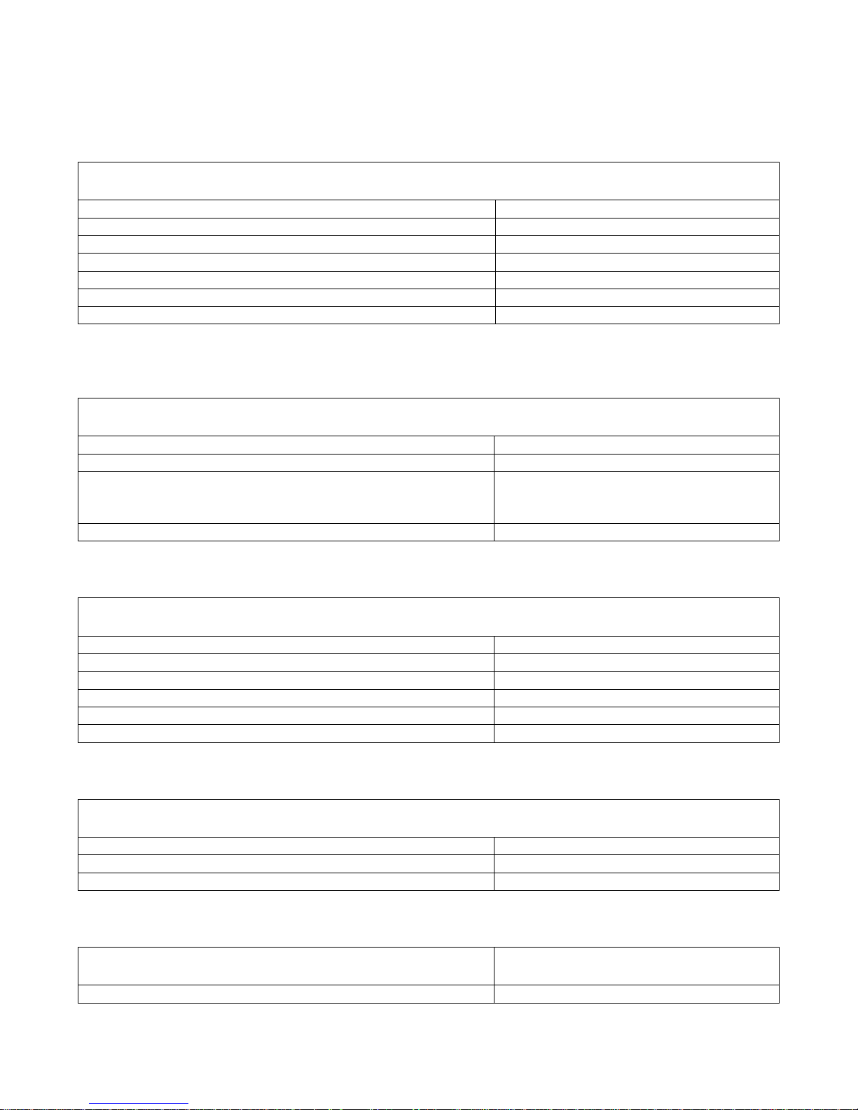
AC Power Requirements
Nominal Operating Range
100 – 240 VAC, 50 - 60 Hz
Min/Max Operating range
90 – 260 VAC, 47 - 63 Hz
Power
< 0.5 Watts Standby
28 Watts Maximum
Fuses (2 required)
5x20 mm, 0.5 A 250 V Slo-Blo® Type
Dimensions
Form Factor
½ Rack Wide, 2 RU High
Depth - excluding knob and connectors
8.33” (220 mm)
Overall Depth - including knob and connectors
9.33” (237 mm)
Width
8.65” (220 mm)
Height - excluding feet
3.47" (88 mm)
Height - including feet
3.88” (99 mm)
Weight
HPA4 only
8 lb.
HPA4 with remote, power cord and manual
9 lb.
Shipp ing weight
12 lb.
Model Numbers
The HPA4 model number is 450-17200-XXX
XXX is a code for the chassis color
Status Display
Type
3.5" Color TFT with Capacitive Touch
Volume Indication - Headphone Output
Bar Graph and dB Gain
Volume Indication - Line Output
Bar Graph and dB Gain
MUTE Indicator
One for Headph on e, One for Line
-20 dB DIM Indicator
Common for Both Output Groups
Input Name
8-Character, User Programmable
Input Connector Display
Input Number, Connector Type
15 Watts Typical Program
Instruction Manual for HPA4 with 1.0.X Firmware – REV B Page 52
Page 53
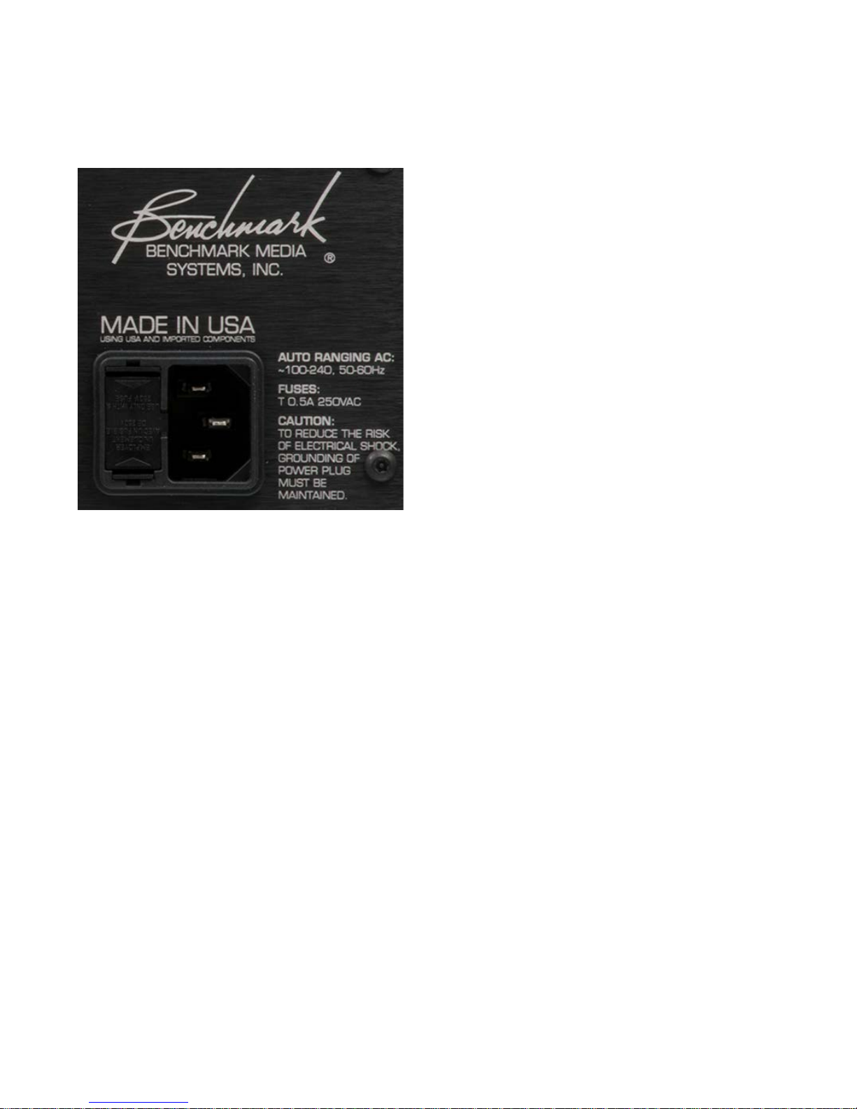
AC Power-Entry and Fuse
Fuses
Module
Input Voltage Range
Caution: For continued fire hazard
protection always replace the fuses with
the correct size and type (T 0.5A 250V, 5
x 20 mm – Littelfuse® Slo-Blo
HXP218.500 or equivalent). The fuse
drawer includes two fuses. Always
replace both fuses at the same time.
®
Note: The HPA4 is equipped with a universal
power supply. There is no voltage selection
switch. AC voltage range is 100 to 240 VAC,
50 to 60 Hz.
Power Cord
Note: The AC power input uses a standard
IEC type connector. One USA-compatible
power cord is included with the HPA4. IEC
style power cords in country-specific
configurations are available in your localit y.
Caution: Always use a grounded power
cord. The HPA4 is equipped with a
standard IEC power entry module. Use
an IEC power cord that is equippe d w ith
the appropriate connector for your
location. Cords are available from your
dealer.
Instruction Manual for HPA4 with 1.0.X Firmware – REV B Page 53
Page 54

Regulatory Compliance
ercury (Hg), Hexavalent Chromium (Cr VI), and flame
FCC Notice (U.S. Only)
NOTICE: This equipment has been tested and found to comply with the limits for a Class B
digital device, pursuant to Part 15 of the FCC Rules. These limits are designed to provide
reasonable protection against harmful interference in a residential installation. This equipment
generates, uses, and can radiate radio frequency energy and, if not installed and used in
accordance with the instructions, may cause harmful interference to radio communications.
However, there is no guarantee that interference will not occur in a particular installation. If
this equipment does cause harmful interference to radio or television reception, which can be
determined by turning the equipment off and on, the user is encouraged to try to correct the
interference by one or more of the following measures:
• Reorient or relocate receiving antenna.
• Increase the separation between the equipment and receiver.
• Connect the equipment into an outlet on a circuit different from that to which the receiver is
connected.
• Consult the dealer or an experienced radio/TV technician for help.
This device complies with Part 15 of the FCC rules. Opera tion is subject to the following two
conditions:
1. This device may not cause harmful interference.
2. This device must accept any interference received including interference that may cause
undesired operation.
NOTICE: Changes or modifications not expressly approved by the party responsible for
compliance could void the user's authority to operate the equipment.
RoHS Compliant Information
This statement clarifies Benchmark Media Systems, Inc. product compliance with the EU’s
(European Union) directive 200 2/95/EC, or, RoHS (Restrictions of Hazardous Substances).
As of July 01, 2006, All Benchmark Media Systems, Inc. products placed on the European Union
market are compliant (containing quantity limit weight less than or equal to 0.1% (1000 ppm)
of any homogeneous Lead (Pb), M
retardant Polybrominated Biphenyls (PBB) or Po lybrominated Diphenyl Ethers (PBDE)).
Instruction Manual for HPA4 with 1.0.X Firmware – REV B Page 54
Page 55
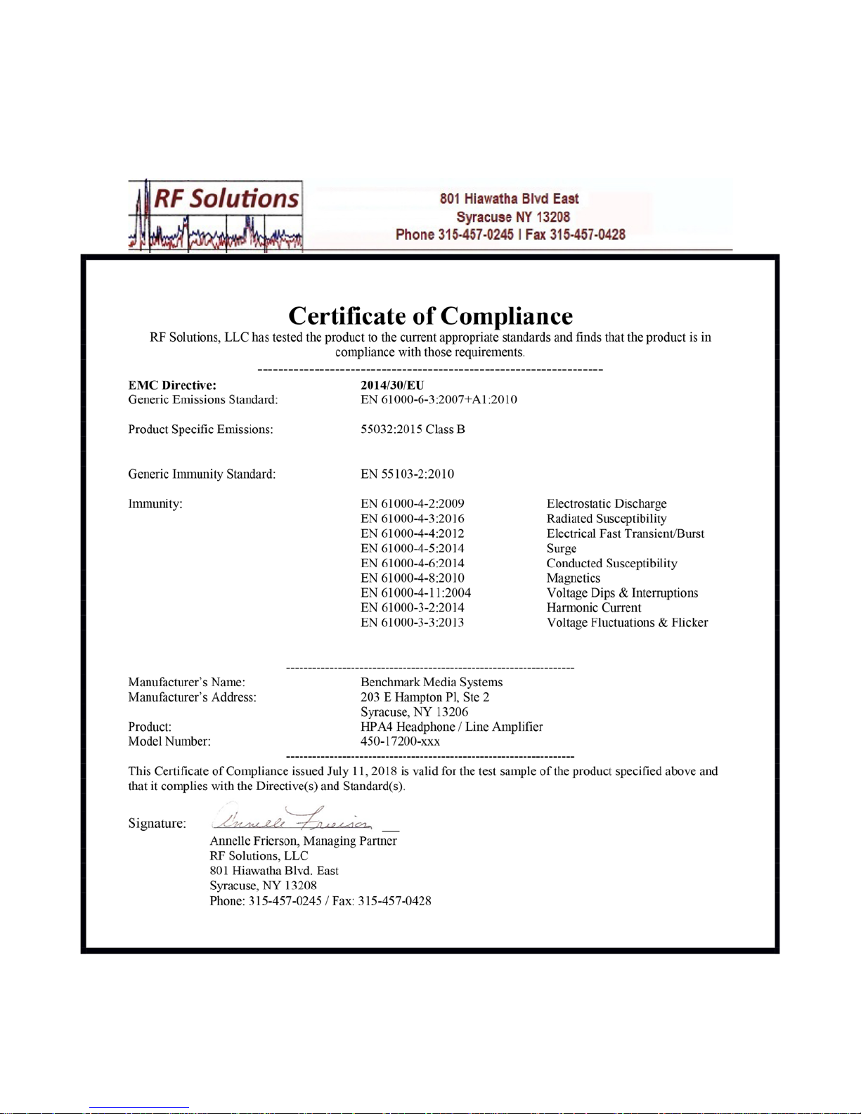
CE Certificate of Compliance
Note: The HPA4 model number is 450-17200-XXX where XXX is a code for the chassis color.
Instruction Manual for HPA4 with 1.0.X Firmware – REV B Page 55
Page 56

Warranty Information
Benchmark 1-Year Warranty
The Benchmark 1-Year Warranty
Benchmark Media Systems, Inc. warrants its products to be free from defects in material and
workmanship under normal use and service for a period of one year from the date of
delivery.
This warranty extend s only to the original purchaser. This warranty does not apply to fuses,
lamps, batteries, or any products or parts that have been subjected to misuse, neglect,
accident, modification, or abnormal operating co nditions.
In the event of failure of a product under this warranty, Benchmark Media Systems, Inc. will
repair, at no charge, the product returned to its factory. Benchmark Media Systems, Inc. may,
at its option, replace the product in lieu of repair. If the failure has been caused by misuse,
neglect, accident, or, abnormal operating conditions, repairs will be billed at the normal shop
rate. In such cas es , an est imate will be submitted before work is started, if requested by the
customer.
Attempts to deliberately deface, mutilate, or remove the product's label will render this
warranty void. Benchmark will not honor warranties for any products disingenuously purchased
on the US or Canadian markets for export.
The foregoing warranty is in lieu of all other warranties, expressed or implied, including but not
limited to any implied warranty of merchantability, fitness or adequacy for any particular
purpose or use. Bench mark Media Systems, Inc. shall not be liable for any special, incidental,
or consequential damages, and reserves the right to change this information without notice.
This limited warranty gives the consumer-owner specific legal rights, and there may also be
other rights that vary from state to state.
Instruction Manual for HPA4 with 1.0.X Firmware – REV B Page 56
Page 57

Benchmark Extended Warranty Options
The Benchmark Extended 5-Year Warranty *
Benchmark Media Systems, Inc. optionally ex tends the standard 1-year warranty to a period of
five years from the date of delivery.
*For the extended warranty to become effective, the original purchaser must register the
product at the time of purchase either by way of the enclosed registration card or through the
product registration section of the Benchmark Me dia Systems, Inc. website. This optional
warranty applies only to products purchased within the US and Ca na da and is extended only to
the original purchaser.
Attempts to deliberately deface, mutilate, or remove the product's label will render this
warranty void. Benchmark will not honor warranties for any products dis ingenuously purchased
on the US or Canadian markets for export. The terms of the extended warranty are subject to
change without notice. For products purchased outside the US and Canada, please refer to the
Extended Two 2-Year International Warranty.
The Benchmark Extended 2-Year International Warranty **
Benchmark Media Systems, Inc. optionally ex tends the standard 1-year warranty to a period of
two years from the date of delivery.
**For the extended warranty to become effective, the original purchaser must register the
product at the time of purchase either by way of the enclosed registration card or through the
product registration section of the Benchmark Me dia Systems, Inc. website. This optional
warranty applies only to products purchased outside the US and Canada and is extended only
to the original purchaser.
Attempts to deliberately deface, mutilate, or remove the product's label will render this
warranty void. Benchmark will not honor warranties for any products disingenuously purchased
on the US or Canadian markets for export. The terms of the extended warranty are subject to
change without notice. For products purchased in within the US and Canada, plea se refer to the
Extended Five 5-Year Warranty.
Notes on Warranty Repairs
An RMA (return merchandise authorization) number, issued by our Customer Service
Department, is required when sending products for repair.
They must be shipped to Benchmark Media Systems prepaid and prefe rably in their original
shipping carton with the RMA number clearly visible o n the exterior of the packaging. A letter
should be included giving full details of the difficulty.
Instruction Manual for HPA4 with 1.0.X Firmware – REV B Page 57
Page 58

Revision B - 7/12/2018
Copyright © 2018
Benchmark Media Systems, Inc.
All rights reserved.
Benchmark Media Systems, Inc.
Benchmark Media Systems, Inc.
203 East Hampton Place, STE 2
Syracuse, NY 13206
USA
PHONE: +1-315-437-6300
FAX: +1-315-437-8119
benchmarkmedia.com
Instruction Manual for HPA4 with 1.0.X Firmware – REV B Page 58
 Loading...