

Page 1

USERS GUIDE
24, 30
For installation guide see reverse of book
When replacing any part on this appliance, use only spare parts that you can be
assured conform to the safety and performance specification that we require.
Do not use reconditioned or copy parts that have not been clearly authorised by Ideal.
Page 2

2
i-mini - User’s
Minimum Clearances
Clearances of 165mm (6 1/2”) above, 100mm (4”) below,
2.5mm (1/8”) at the sides and 450mm (17 3/4”) at the front of
the boiler casing must be allowed for servicing.
Bottom clearance
Bottom clearance after installation can be reduced to 5mm.
This must be obtained with an easily removable panel, to
enable the consumer to view the system pressure gauge, and
to provide the 100mm clearance required for servicing.
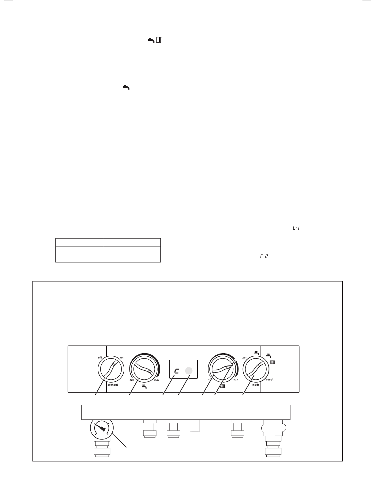
To light the boiler. Refer to Frame 1
1. CHECK THAT THE ELECTRICITY SUPPLY TO BOILER IS
OFF.
2. Set the mains mode knob control (D) to ‘Off’.
3. Set the Domestic Hot Water temperature control (B) and
Central Heating temperature control (C) to ‘max’.
4. Set the preheat control (A) to ‘on’.
5. Ensure that all hot water taps are turned off.
6. Switch ON electricity to the boiler and check that all
controls, e.g. timer and room thermostat, are ON (refer to
mechanical timer instructions - Page 4).
7. Set the mode knob control to winter (
).
The boiler will commence the ignition sequence, rst supplying
heat to preheat the domestic hot water and then to the central
heating, if required.
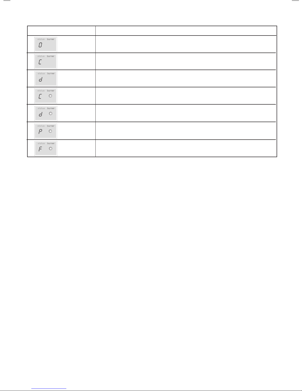
Note. In normal operation the boiler status display (E) will
show codes:
Standby - no demand for heat.
CH being supplied.
DHW being supplied.
DHW preheat.
Boiler frost protection - boiler will re if temperature is
below 5 degrees C.
During normal operation the burner on indicator (F) will remain
illuminated when the burner is lit.
Note: If the boiler fails to light after ve attempts the fault code
will be displayed.
RESET PROCEDURE
To reset boiler, turn the mode control knob (D) to reset position
and immediately turn knob back to required setting. The boiler
will repeat the ignition sequence. If the boiler still fails to light
consult a Gas Safe Registered Engineer or in IE a Registered
Gas Installer (RGII).
Introduction
The i-mini is a wall mounted, room sealed, condensing combination
boiler, featuring full sequence automatic spark ignition and fan
assisted combustion.
Due to the high efciency of the boiler, condensate is produced from
the ue gases and this is drained to a suitable disposal point through
a plastic waste pipe at the base of the boiler. A condensate ‘plume’
will also be visible at the ue terminal.
The i-mini is a combination boiler providing both central heating and
instantaneous domestic hot water.
Safety
Current Gas Safety (Installation & Use)
Regulations or rules in force.
In your own interest, and that of safety, it is the law that this boiler
must be installed by a Gas Safe Registered Engineer, in accordance
with the above regulations.
In IE, the installation must be carried out by a Registered Gas Installer
(RGII) and installed in accordance with the current edition of I.S. 813
“Domestic Gas Installations”, the current Building Regulations and
reference should be made to the current ETCI rules for electrical
installation.
It is essential that the instructions in this booklet are strictly followed,
for safe and economical operation of the boiler.
Electricity Supply
This appliance must be earthed.
Supply: 230 V ~ 50 Hz. The fusing should be 3A.
Important Notes
This appliance must not be operated without the casing correctly
tted and forming an adequate seal.
If the boiler is installed in a compartment then the compartment
MUST NOT be used for storage purposes.
If it is known or suspected that a fault exists on the boiler then
it MUST NOT BE USED until the fault has been corrected by a
Gas Safe Registered Engineer or in IE a Registered Gas Installer
(RGII).
Under NO circumstances should any of the sealed components on
this appliance be used incorrectly or tampered with.
This appliance is not intended for use by persons (including
children) with reduced physical, sensory or mental capabilities, or
lack of experience and knowledge, unless they have been given
supervision or instructions concerning use of the appliance by a
person responsible for their safety.
Children should be supervised to ensure that they do not play with
the appliance.
In cases of repeated or continuous shutdown a Gas Safe Registered
Engineer or in IE a Registered Gas Installer (RGII) should be called
to investigate and rectify the condition causing this and carry out an
operational test. Only the manufacturers original parts should be used
for replacement.
THE BENCHMARK SERVICE INTERVAL RECORD MUST BE COMPLETED AFTER EACH SERVICE
Ideal Heating, is a member of the Benchmark scheme and fully supports the aims of the
programme. Benchmark has been introduced to improve the standards of installation and
commissioning of central heating systems in the UK and to encourage the regular servicing of all
central heating systems to ensure safety and efciency.
All Gas Safe Register installers carry a Gas Safe Register ID card, and have a registration number. Both should be recorded in the
Benchmark Commissioning Checklist. You can check your installer by calling Gas Safe Register direct on 0800 4085500.
FOR ANY QUERIES PLEASE RING THE
IDEAL CONSUMER HELPLINE : 08708498057
NOTE. BOILER RESET PROCEDURE To reset boiler, turn mode control knob to reset position and immediately turn knob back to required setting.
Page 3
3i-mini - User’s
Legend
A. Pre-heat On/Off
B. DHW Temperature Control
C. CH Temperature Control
1 BOILER CONTROLS
Operation
Winter conditions - i.e. CH and DHW required.
Ensure the mode knob control (D) is set to winter ( )
The boiler will re and supply heat to the radiators but will give
priority to DHW on demand.
The DHW preheat will operate as described under ‘Summer
conditions’ during periods when there is no call for CH.
Summer conditions - i.e. DHW only required.
Set the mode knob control to Summer ( ).
Set the CH external controls to OFF.
Preheat will operate with the preheat switch (A) set to ON.
The boiler will re periodically for a few seconds to maintain the
DHW calorier in a preheated condition. The average time period
between ring is 90 minutes. This may vary considerably due to
the surrounding ambient temperature of the boiler. The boiler will
re whenever there is a demand for DHW.
The boiler preheat facility can be immobilised by turning the
preheat switch (A) to OFF. This will stop the boiler operating
for short periods. This facility is primarily provided for boiler
installations in a sensitive area (i.e. bedroom etc.)
Note. The pump will operate briey as a self-check once every 24
hours, regardless of system demand.
Control of water temperature
Domestic Hot Water
The DHW temperature is limited by the boiler controls to
64oC maximum at low draw-off rate, adjustable via the DHW
temperature control (B).
Due to system variations and seasonal temperature uctuations
DHW ow rates/temperature rise will vary, requiring adjustment
at the draw off tap : the lower the rate the higher the temperature,
and vice versa.
Central Heating
The boiler controls the central heating radiator temperature to a
maximum of 80oC, adjustable via the CH temperature control (C).
The i-mini is a high efciency combination boiler which is most
efcient when operating in condensing mode.
The boiler will operate in this mode if the CH temperature control
(C) is set to the ‘e’ position (economy mode). This control should
be set to maximum for very cold periods
To shut down the boiler
Set the mode knob control to OFF
To relight the boiler
Repeat the procedure detailed in ‘To light the boiler’.
Frost protection
If no system frost protection is provided and frost is likely during
a short absence from home, leave the heating controls (if tted)
at a reduced temperature setting. For longer periods, the entire
system should be drained.
If the system includes a frost thermostat then, during cold
weather, the boiler should be turned OFF at the time switch (if
tted) ONLY. The mains supply should be left switched ON, with
the boiler thermostat left in the normal running position.
Boiler Overheat Protection
The boiler controls will shut down the boiler in the event of
overheating. Should this occur, a fault code will be displayed.
Refer to fault chart.
Flame Failure
Should this occur a fault code will be displayed. Refer to fault
chart.
G
H
A B E F C DJ
Approx. ow temperatures for the boiler thermostat settings are:
Knob Setting Flow Temperature
Minimum 40oC (104oF)
Maximum 64
o
C (147oF)
D. Mode Control
E. Boiler Status
F. Burner ‘on’ Indicator
G. Pressure Gauge
H. Condensate Drain
J. Economy Mode
continued . . . . . .
Page 4
4
i-mini - User’s
Condensate Drain
This appliance is tted with a siphonic condensate trap
system that reduces the risk of the appliance condensate
from freezing. However should the condensate pipe to this
appliance freeze, please follow these instructions:
a. If you do not feel competent to carry out the defrosting
instructions below please call your local Gas Safe
Registered installer for assistance.
b.
If you do feel competent to carry out the following instructions
please do so with care when handling hot utensils. Do not
attempt to thaw pipework above ground level.
If this appliance develops a blockage in its condensate pipe,
its condensate will build up to a point where it will make a
gurgling noise prior to locking out an “L2” fault code. If the
appliance is reset it will make a gurgling noise prior to it
locking out on a failed ignition “L2” code.
To unblock a frozen condensate pipe;
1. Follow the routing of the plastic pipe from its exit point on
the appliance, through its route to its termination point.
Locate the frozen blockage. It is likely that the pipe is
frozen at the most exposed point external to the building
or where there is some obstruction to ow. This could
be at the open end of the pipe, at a bend or elbow, or
where there is a dip in the pipe in which condensate can
collect. The location of the blockage should be identied
as closely as possible before taking further action.
2. Apply a hot water bottle, microwaveable heat pack or a
warm damp cloth to the frozen blockage area. Several
applications may have to be made before it fully defrosts.
Warm water can also be poured onto the pipe from a
watering can or similar. DO NOT use boiling water.
3. Caution when using warm water as this may freeze and
cause other localised hazards.
4. Once the blockage is removed and the condensate can
ow freely, reset the appliance. (Refer to “To Light the
boiler”)
5. If the appliance fails to ignite, call your Gas Safe
Registered engineer.
Preventative solutions
During cold weather, set the boiler stat to maximum, (Must
return to original setting once cold spell is over)
Place the heating on continuous and turn the room stat down
to 15ºC overnight or when unoccupied. (Return to normal
after cold spell).
Escape of gas
Should a gas leak or fault be suspected contact the National
Gas Emergency Service without delay. Telephone 0800 111
999
Do NOT search for gas leaks with a naked ame.
Cleaning
For normal cleaning simply dust with a dry cloth.
To remove stubborn marks and stains, wipe with a damp
cloth and nish off with a dry cloth.
DO NOT use abrasive cleaning materials.
Maintenance
The appliance should be serviced at least once a year by
a Gas Safe Registered Engineer or in IE a Registered Gas
Installer (RGII).
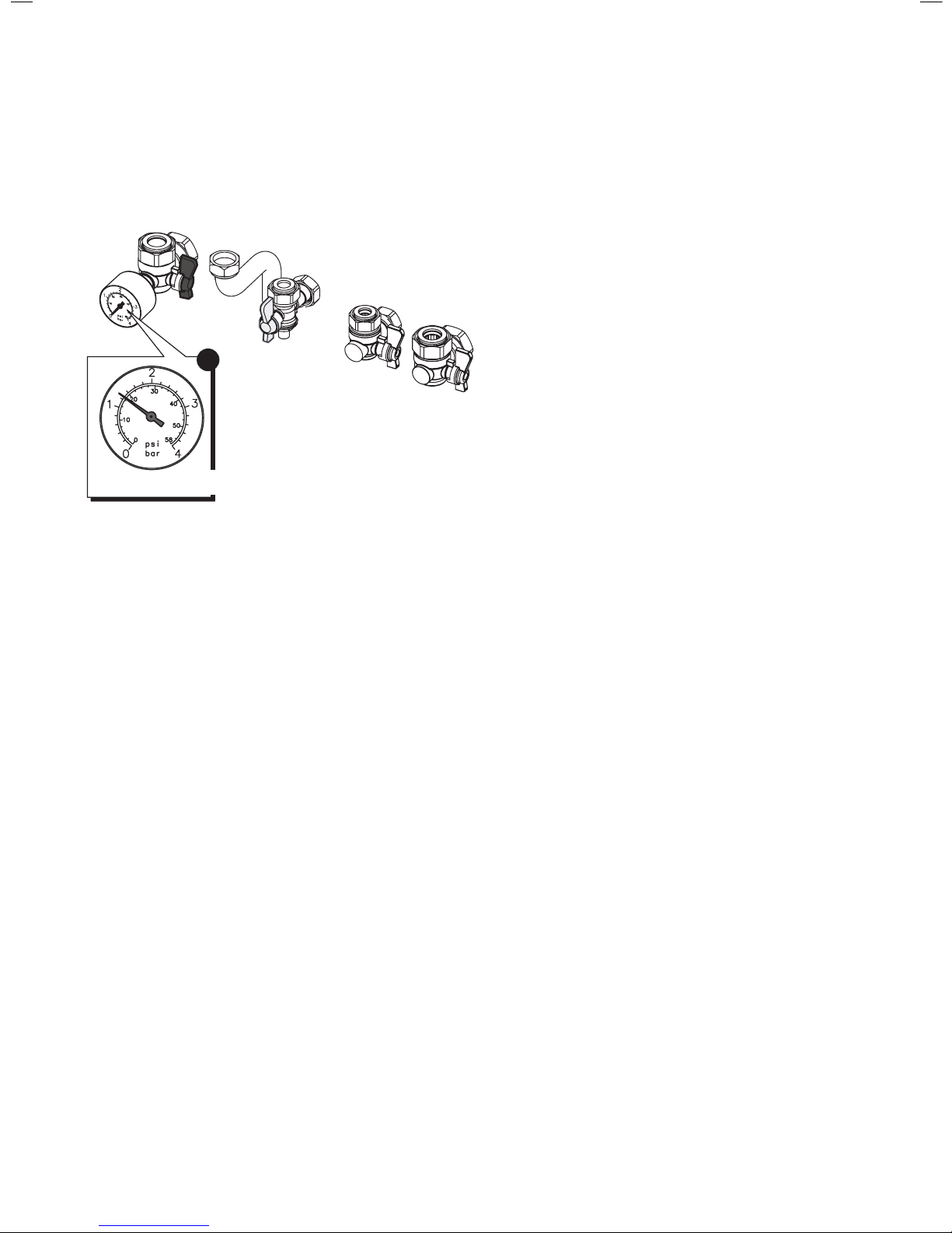
Loss of system water pressure
The gauge (G) indicates the central heating system pressure. If
the pressure is seen to fall below the original installation pressure
of 1-2 bar over a period of time then a water leak may be
indicated. In this event the re-pressurise the boiler. If unable to
do so or if the pressure continues to drop a Gas Safe Registered
Engineer or in IE a Registered Gas Installer (RGII) should be
consulted.
THE BOILER WILL NOT OPERATE IF THE PRESSURE HAS
REDUCED TO LESS THAN 0.3 BAR UNDER THIS CONDITION.
3
3G9933
5
PRESSURE GAUGE
Page 5
5i-mini - User’s
YES
YES
POINTS FOR THE BOILER USER
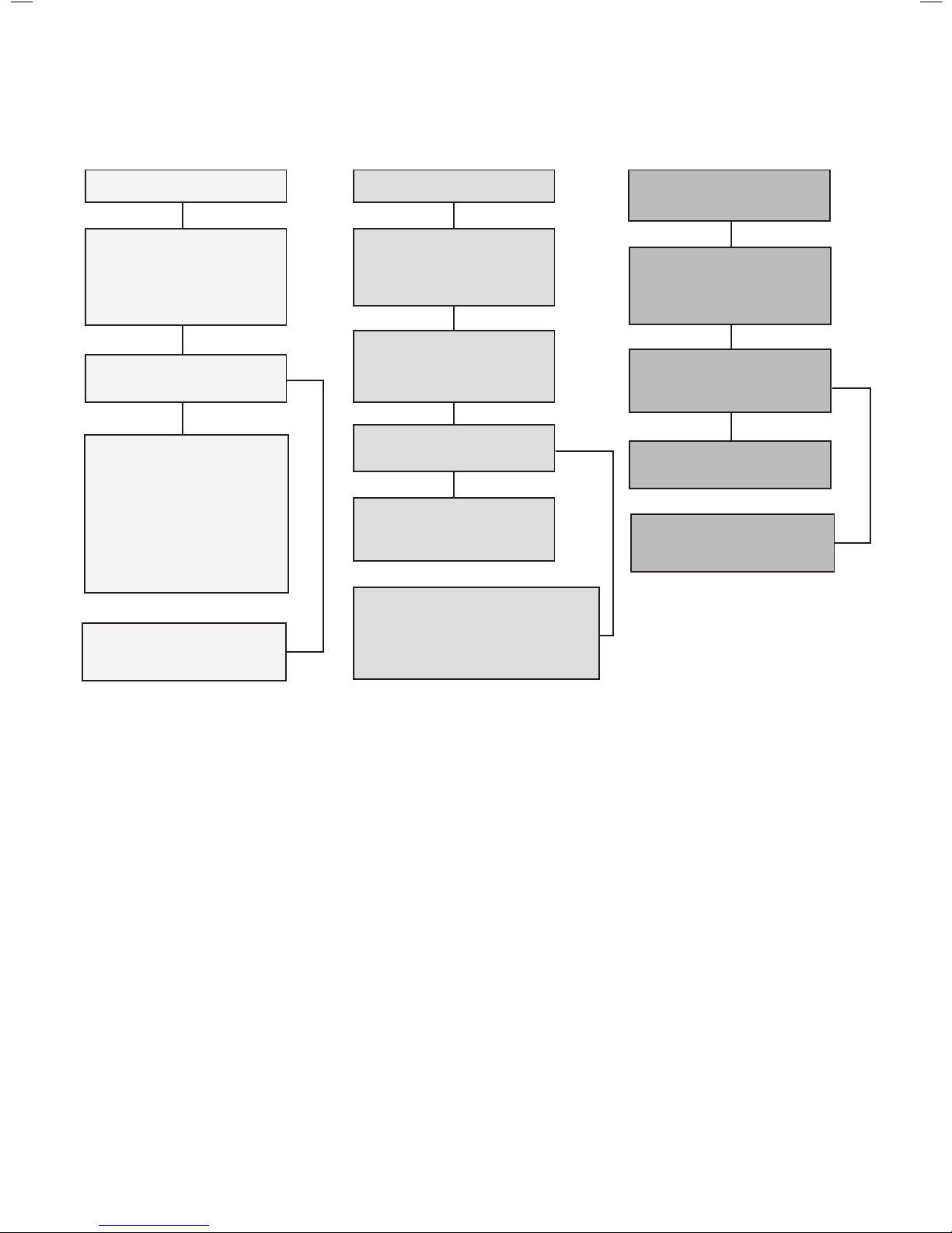
Note. In line with our current warranty policy we would ask that you check through the Troubleshooting guide to identify any problems
external to the boiler prior to requesting a service engineers visit. Should the problem be found to be other than with the appliance we
reserve the right to levy a charge for the visit, or for any pre-arranged visit where access is not gained by the engineer.
NO HOT WATER
Check the mains switch (fused
spur) is turned on and ensure
switch mode control knob (D) is
in the summer or winter position
Is water coming out of the hot
water tap when turned on?
NO CENTRAL HEATING
Check the mains switch (fused
spur) is turned on and ensure
switch mode control knob (D) is
in the winter position
Does the boiler operate and
provide central heating?
Check the time settings on the
programmer are as you require
and adjust if necessary
Check the timer (internal or
external to the boiler) is in an
“ON” position and the room
thermostat is turned up
NO HOT WATER OR
CENTRAL HEATING
Check the fused spur is turned
on and ensure switch mode
control knob (D) is in the winter
position
See boiler “Operation Modes”
and “Fault Codes” section
Does the boiler have a display
showing on the front control
panel?
See boiler “Fault Codes”
section. If ‘0’ is displayed then
contact Ideal Customer Services
Helpline if your appliance is
under warranty or a Gas Safe
Registered Engineer, in IE a
Registered Gas Installer (RGII),
if out of warranty
YES
NO
Contact a Gas Safe Registered
Engineer or in IE a Registered
Gas Installer (RGII)
NO
See boiler “Operation Modes” and
“Fault Codes” section. If “0” is
displayed then contact a Gas Safe
Registered Engineer or in IE a
Registered Gas Installer (RGII)
NO
Contact a Gas Safe Registered
Engineer or in IE a Registered
Gas Installer (RGII)
TROUBLESHOOTING
Page 6
6
i-mini - User’s
continued . . . . . .
DISPLAY CODE ON BOILER
DESCRIPTION
The boiler is in standby mode awaiting either a central heating call or hot water demand.
The boiler has a call for central heating but the appliance has reached the desired
temperature set on the boiler.
The boiler has a call for hot water but the appliance has reached the desired temperature set on
the boiler.
The boiler is operating in central heating mode.
The boiler is operating in pre heat mode.
The boiler is operating in hot water mode.
The boiler is operating in frost mode.
OPERATION MODES
Page 7
7i-mini - User’s
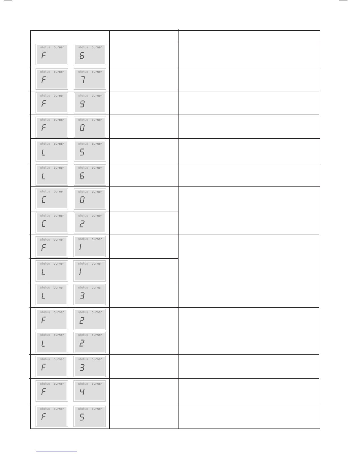
Outside Sensor Failure
Reset the appliance - if the boiler fails to operate then please contact
Ideal (if under warranty) or alternatively a Gas Safe Registered
Engineer if outside of the warranty period. In IE contact a Registered
Gas Installer (RGII).
Low Mains Voltage
Contact a qualied electrician or your electricity provider.
Uncongured PCB
Uncongured PCB. Please contact Ideal (if under warranty) or
alternatively a Gas Safe Registered Engineer if outside of the warranty
period. In IE contact a Registered Gas Installer (RGII).
No Water Flow Thermistor
Reset the appliance - if the boiler fails to operate then please contact
Ideal (if under warranty) or alternatively a Gas Safe Registered
Engineer if outside of the warranty period. In IE contact a Registered
Gas Installer (RGII).
5 Boiler Resets in 15 minutes
1. Turn power off and on at the fused spur.
2. If the boiler fails to operate please contact Ideal (if under warranty) or
alternatively a Gas Safe Registered Engineer if outside of the warranty
period. In IE contact a Registered Gas Installer (RGII).
False Flame Lockout
Reset the appliance - if the boiler fails to operate then please contact
Ideal (if under warranty) or alternatively a Gas Safe Registered
Engineer if outside of the warranty period. In IE contact a Registered
Gas Installer (RGII).
BCC Activation Fault
Reset the appliance - if the boiler fails to operate then please contact
Ideal (if under warranty) or alternatively a Gas Safe Registered
Engineer if outside of the warranty period. In IE contact a Registered
Gas Installer (RGII).
DISPLAY CODE ON BOILER
DESCRIPTION
Low Water Pressure
ACTION
Check system pressure is between 1 & 1.5bar on the pressure gauge.
If the boiler fails to operate then please contact Ideal (if under warranty)
or alternatively a Gas Safe Registered Engineer if outside of the
warranty period. In IE contact a Registered Gas Installer (RGII).
Flame Loss
1. Check other gas appliances in the house are working to conrm a
supply is present in the property.
2. If other appliances do not work or there are no other appliances,
check the gas supply is on at the meter and/or pre payment meter
has credit. If the boiler fails to operate then please contact Ideal (if
under warranty) or alternatively a Gas Safe Registered Engineer
if outside of the warranty period. In IE contact a Registered Gas
Installer (RGII).
Fan Fault
Reset the appliance - if the boiler fails to operate then please contact
Ideal (if under warranty) or alternatively a Gas Safe Registered
Engineer if outside of the warranty period. In IE contact a Registered
Gas Installer (RGII).
Flow Thermistor
Reset the appliance - if the boiler fails to operate then please contact
Ideal (if under warranty) or alternatively a Gas Safe Registered
Engineer if outside of the warranty period. In IE contact a Registered
Gas Installer (RGII).
Return Thermistor
Reset the appliance - if the boiler fails to operate then please contact
Ideal (if under warranty) or alternatively a Gas Safe Registered
Engineer if outside of the warranty period. In IE contact a Registered
Gas Installer (RGII).
FAULT CODES
Flow Temperature Overheat
No Water Flow
BCC Fault
Page 8

6
i-mini - User’s
 Loading...