

Page 1
_____________________________________________________________________________________
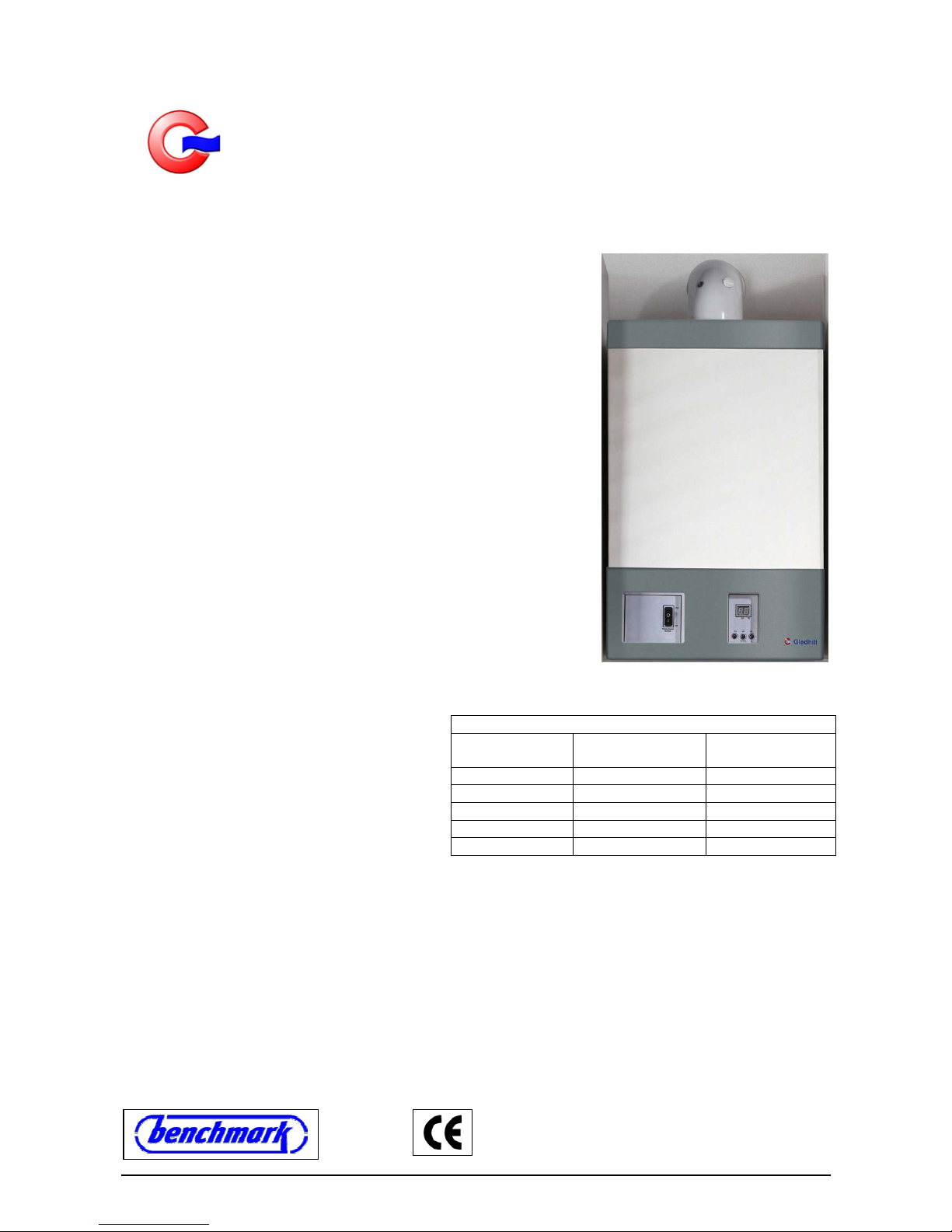
A wall mounted high efficiency condensing Gledhill Boiler
DESIGN, INSTALLATION AND SERVICE INSTRUCTIONS
_____________________________________________________________________________________
GENERAL
This high efficiency wall mounted condensing boiler is designed to
provide central heating from a fully pumped open vented or sealed
water system when coupled to a thermal store or an indirect cylinder.
The central heating water temperature can be adjusted by the installer
to suit special applications.
Once the controls are set, the boiler operates automatically and the
boiler controller automatically activates the frost protection program to
prevent the boiler from freezing.
This boiler is for use with Natural Gas (G20) only at 20mbar inlet
pressure and is for use in GB &IE only.
Appliance category: I
2H
Appliance types: C13, C73, C
33
These instructions cover the following boiler models and only apply to
the appliances sold and installed in Great Britain (GB) and Ireland (IE).
These appliances have been certified for safety and therefore it is
important these instructions must be followed. Both the appliance and
the installation specifications must not be modified unless
recommended and approved by Gledhill Limited in writing. Any
alteration not approved by Gledhill Ltd., could invalidate the
certification, boiler warranty and may also infringe the current issue of statutory requirements.
The Gas Safety (Installation and use)
Regulations 1998
“In your own interest, and that of safety, it is law
that all gas appliances are installed by
competent persons, in accordance with the
above regulations. Failure to install appliances
correctly could lead to prosecution.”
Control of Substances Harmful to Health
When working with insulation materials, avoid inhalation as it may be harmful to health. Avoid contact with
skin, eyes, nose and throat. Use disposable protection. Dampen the material and ensure that the area is well
ventilated.
INSTRUCTIONS
The instructions are an integral part of the appliance and therefore read these Instructions before installing or
lighting the appliance. Also to comply with the current issue of the Gas Safety (Installation and Use), these
instructions and the ‘Benchmark’ Log Book must be handed to the user on completion of the installation.
VER: 02.3 _260505 Page:1/41
Gledhill wall mounted condensing boiler models
Model
Reference
SEDBUK Rating Gas Council
Number
GB10 90.1 % - Band ‘A’
GB15 90.3 % - Band ‘A’
GB20 90.4 % - Band ‘A’
GB25 90.4 % - Band ‘A’
GB30 90.3 % - Band ‘A’
Page 2

Contents
Page
1. IMPORTANT INFORMATION 3
2. OPERATING THE BOILER 7
3. INSTALLATION, DESIGN & PLANNING INFORMATION 9
4. BOILER INSTALLATION 21
5. ELECTRICAL WIRING 23
6. COMMISSIONING 26
7. SERVICING 28
8. FAULT FINDING 30
9 REPLACEMENT OF PARTS 35
10. SPARE PARTS 38
VER: 02.3 _260505 Page:2/41
Page 3

1. IMPORTANT INFORMATION
1.1.
GAS TESTING AND CERTIFICATION AND CE MARK
These boilers have been tested and certified for safety and performance. It is important that no alteration is
made to the boiler unless it is approved in writing by Gledhill Ltd.
The boiler meets the requirements of Statutory Instrument No 3083 i.e. ‘The Boiler (Efficiency) Regulations’
and therefore it is deemed to meet the requirements of Directive 92/42/EEC. The product has been certified
by the Notified body Advantica 0087 and the production is certified by the notification body BSI 0086.
The CE mark on this appliance shows compliance with:
(a) Directive 90/396/EEC on the approximation of laws relating to appliances burning gaseous fuels.
(b) Directive 73/23/EEC on the harmonisation of laws of the Member States relating to electrical equipment
designed for use within certain voltage limits.
(c) Directive 89/336/EEC on the approximation of the laws of Member States relating to electromagnetic
compatibility.
1.2.
SPARE PARTS
When replacing spare parts on this appliance, remember to use only spare parts that you can be assured to
conform to the safety and performance specification that we require. Do not use reconditioned or copy parts
that have not been clearly authorised by Gledhill Ltd.
1.3.
HANDLING AND STORING THE APPLIANCE
This appliance should be handled carefully to avoid damage and any manual handling/lifting operations will
need to comply with the requirements of the Manual Handling Operations Regulations issued by the H.S.E.
During the appliance installation it will be necessary to employ caution and assistance whilst lifting as the
appliance or component exceeds the recommended weight for a one man lift.
Take care to avoid trip hazards, slippery or wet surfaces. In certain situations it may be necessary to use
mechanical handling aids.
If the unit needs to be stored prior to installation it should be stored upright in a dry environment and on a
level base.
1.4.
SYSTEM INSTALLATION
Any installation must be in accordance with the relevant requirements of the current issue of Gas Safety
(Installation and Use) Regulations, Local Building Regulations, Local Water Company Bylaws and Health &
Safety Document No. 635 – The Electricity at Work Regulations 1989. The detailed recommendations are
contained in the current issue of the following British Standards and Codes of Practices: -
BS 5440 Pts. 1 & 2; BS 5449; BS 5546; BS 7074 Part 1; BS 6700; BS 6798; BS 6891, BS 7593,
IGE/UP/7/1998
1.5.
WARNINGS
(a) Gas Leak or Fault
If a gas leak or fault exists or is suspected, turn the boiler mains electricity supply off and turn off the
gas supply at the meter. Consult your local gas company or your local installation/servicing company.
VER: 02.3 _260505 Page:3/41
Page 4

(b) Clearances
If fixtures are positioned close to the boiler, space must be left as shown in figure 3.10.2. Enough space
must also be left in front of the boiler to allow for servicing.
(c) Sheet Metal Parts
This boiler contains metal parts (case & components) and therefore care should be taken when
handling and cleaning, with particular regard to edges.
(d) Sealed Components
This boiler uses fully premix burner with air/gas ratio controller therefore the burner input i.e. CO and
CO
2
settings and the burner off set pressure are factory set and sealed and require no onsite
adjustments during installation or routine servicing.
Under no circumstances the user should interfere with the sealed components as this could result in a
potentially dangerous situations arising. If sealed components in the appliance are replaced and/or recommissioned in the field then these must be done strictly in accordance with manufacturer’s
instructions and these components must be re-sealed.
(e) Bench Mark Log Book
As part of the industry wide ‘Benchmark’ initiative all Gledhill appliances now include a Benchmark
Installation, Commissioning and Service Record Logbook. Please read this carefully and complete all
sections relevant to this appliance.
Failure to do so may affect warranty.
1.6.
EQUIPMENT SELECTION
This information is provided to assist generally in the selection of equipment. Responsibility for selection and
specification of our equipment must, however, remain that of our customers and any expert or consultants
concerned with the installation(s). Therefore please note that: -
(a) We do not therefore accept any responsibility for matters of design selection or specification for the
effectiveness of an installation containing one of our products.
(b) All goods are sold subject to our Conditions of Sale, which are set out in the Appendix to this
document.
1.7.
ELECTRICITY SUPPLY FAILURE
(a) This boiler must be earthed and the boiler will not work without an electricity supply.
(b) Reset any external controls to resume normal operation of the central heating.
(c) Normal operation of the boiler should resume when the electrical supply is restored. If the boiler does
not resume normal operation turn the mains switch off and on. If the boiler does not resume normal
operation after this, the overheat thermostat may have operated. The overheat thermostat would only
operate under abnormal conditions and, under these circumstances it would be advisable to consult
your installation/servicing company.
1.8.
PROTECTION AGAINST FREEZING
(a) The boiler has built in frost protection programme as long as the electricity and gas are left switched on.
The boiler controller operates the burner and the system pump when the temperature inside the boiler
falls below 4
o
C.
(b) Any other exposed areas of the heating and hot water system should be protected by a separate frost
thermostat.
(c) If the mains electricity and gas supplies to the boiler system are to be turned off for any long periods
during severe weather, it is recommended that the whole system including the boiler should be drained
to avoid risk of freezing. In this case ensure that the immersion heater in the cylinder if fitted is switched
off.
VER: 02.3 _260505 Page:4/41
Page 5

(d) If you have a sealed heating system, contact your installation/service company as draining, refilling and
pressurising MUST be carried out by a competent person.
(e) As a safety feature, the boiler will stop working if the condensate drain becomes blocked. During
freezing conditions this may be due to the forming of ice in the condensate drain external to the house.
Release ice blockage by use of warm cloths on the pipe. Contact your installation/service company if
the fault persists.
1.9.
BOILER INSTALLATION IN A COMPARTMENT OR CUPBOARD
If the boiler is fitted into a compartment or a cupboard, it does not require ventilation openings. However, do
not use the compartment or cupboard for storage.
1.10.
BOILER CASING
Do not remove or adjust the casing in any way, as the incorrect fitting may result in incorrect operation or
failure to operate at all.
1.11.
CONDENSATE DRAIN
The condensate drain must not be modified or blocked (See section 3.13)
1.12.
PLUMING FROM FLUE TERMINAL
This is a high efficiency-condensing boiler and hence flue gas temperature will be low. Therefore like all
condensing boilers this appliance will produce a plume of condensation in cool weather. It is normal and not
a fault condition, but this should be taken into account when positioning the boiler.
1.13.
CLEANING
This boiler contains metal parts and therefore care should be taken when handling and cleaning, with
particular regard to edges.
The boiler casing can be cleaned using a mild liquid detergent with a damp cloth and then a dry cloth to
polish. Do not use any form of abrasive or solvent cleaner as you may damage the finish.
1.14.
MAINTENANCE AND SERVICING
This appliance must be serviced and installed by a competent person e.g. CORGI Registered installer. All
CORGI registered installers carry a CORGI ID Card and have a registration number. You can call CORGI
direct on 01256 372300.
For the continued efficient and safe operation of the boiler, it is recommended that it is checked and serviced
at regular intervals. The frequency of service will depend upon the installation condition and usage, but in
general, once a year should be enough.
If this boiler is installed in a rented property, there is a duty of care imposed on the owner of the property by
the current issue of the Gas Safety (Installation and Use) regulations, Section 35.
The installation / service engineer should complete the ‘Benchmark’ logbook on completion of commissioning
and service work.
VER: 02.3 _260505 Page:5/41
Page 6

1.15.
REPLACEMENT PARTS
Free of charge replacement for any faulty components are available from Gledhill Ltd during the in-warranty
period (normally 12 months).
After this the spares can be obtained direct from Gledhill Ltd using the ‘Speed Spares’ service. Help and
advice is also available from our Technical Help Line on 01253 474401.
Please quote the name and model of the appliance when requesting for help or ordering spares. This
information will be on the front of the appliance next to the main switch.
1.16.
CONTINUOUS IMPROVEMENTS
In the interest of continuously improving the Gledhill Boiler
range, Gledhill Water Storage Ltd reserves the
right to modify the product without notice and in these circumstances this booklet, which is accurate at the
time of printing, should be disregarded.
VER: 02.3 _260505 Page:6/41
Page 7
2. OPERATING THE BOILER
2.1. HEATING SYSTEM AND BOILER
(a) Sealed Systems
A sealed heating system must be filled and pressurised by a competent person. Only light the boiler
when you are sure that the system and the boiler have been filled and pressurised.
The pressure should read at least 0.5bar, anything less than this figure could indicate a leak and you
MUST contact your installation / servicing company.
(b) All Systems
Check that the electrical supply to the boiler is ON at the external system isolator. Set any remote
controls as required.
This is a fan flued appliance and therefore the fan operation may be heard. The boiler flow temperature
is factory set at 80±2
o
C and is not user adjustable. (Note: The boiler flow temperature can be adjusted
between 60 and 80
o
C by the installer for special applications)
2.2. USER CONTROLS
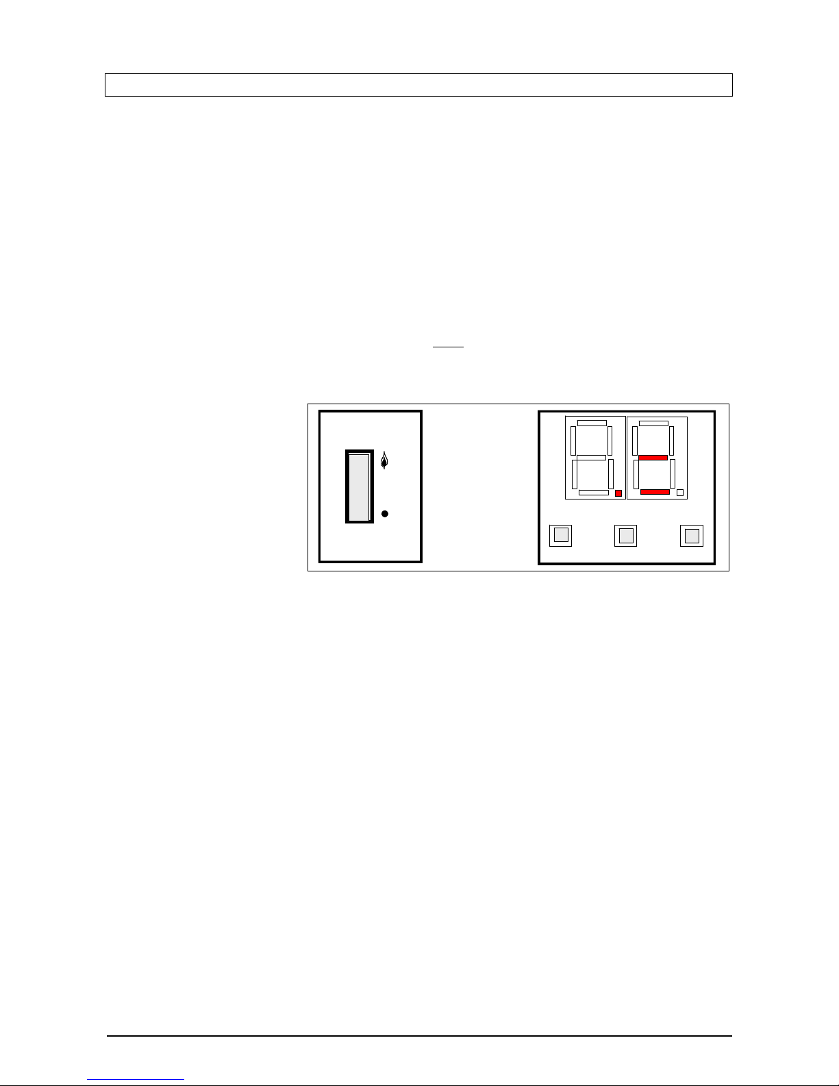
The appliance control panel is
shown in diagram 2.1. The
appliance on-off switch should
be left in the ON position
(indicated by flame symbol) for
normal operation otherwise the
built in boiler frost protection will
not function.
The two-digit display indicates
the status of the boiler and the
push buttons are used for setting and resetting the controller as shown in diagram 2.2.
S3
S2
Set/Reset
-
+
S1
Mains/Reset
Switch
D1
D2
0
I
Diagram 2.1
a1
a2
S3
S2
Set/Reset
-
+
S1
Mains/Reset
Switch
D1
D2
0
I
Diagram 2.1
a1
a2
(a) Central heating and hot water
Switch the boiler on-off switch to position ‘ON’ position indicated by a ‘flame’ symbol and the dot D1 will
begin to flash to indicate that the boiler controller is active.
Set the remote user controls e.g. programmer and room thermostat so that hot water heating and/or
central heating demands are active.
When the boiler senses the heating demand, indicated by horizontal bar ‘a2’, the boiler switches on the
boiler pump (indicated by bar ‘a1’) and starts the boiler firing sequence.
When the boiler has lit, the dot D1 will stop flashing and will be on constantly.
If the boiler fails to ignite, the dot D1 will switch off and dot D2 will either be either flashing or be on
constantly (depending upon the error type) and reset will be required.
When the demand for boiler firing stops i.e. heat is not required for space heating or hot water, the boiler
will stop firing and this will be indicated by flashing dot D1 and bar a2 will switch off. After a period of
about 3 minutes the boiler pump will switch off indicated by bar a1.
(b) To Reset Boiler
Press reset button S1. If the dot D1 starts to flash and the dot D2 switches off, the boiler has reset. If the fault
persists contact your installer/service provider.
VER: 02.3 _260505 Page:7/41
Page 8

2.3. TO TURN THE BOILER OFF
Turn the mains /reset switch to the off position (indicated by disc). Turn the gas supply off at the gas service
cock if the boiler is to be out of use for some time.
D1
flashing
D2
Controller on standby
Boiler off
D1
flashing
D2
Boiler in Ignition sequence
Boiler heat demand present
Boiler pump on
D1
ON
D2
Boiler has lit
Boiler heat demand present
Boiler pump on
D1
flashing
D2
Boiler off
Heat demand not present
Boiler pump on
D1
on
D2
Frost protection program on
Boiler pump on
D1
D2
On/flashing
Boiler lockout error
Reset required
Diagram 2.2 Boiler display indication
D1
flashing
D2
Controller on standby
Boiler off
D1
flashing
D2
Boiler in Ignition sequence
Boiler heat demand present
Boiler pump on
D1
ON
D2
Boiler has lit
Boiler heat demand present
Boiler pump on
D1
flashing
D2
Boiler off
Heat demand not present
Boiler pump on
D1
on
D2
Frost protection program on
Boiler pump on
D1
D2
On/flashing
Boiler lockout error
Reset required
D1
flashing
D2
D1
flashing
D2
Controller on standby
Boiler off
D1
flashing
D2
D1
flashing
D2
Boiler in Ignition sequence
Boiler heat demand present
Boiler pump on
D1
ON
D2
D1
ON
D2
Boiler has lit
Boiler heat demand present
Boiler pump on
D1
flashing
D2
D1
flashing
D2
Boiler off
Heat demand not present
Boiler pump on
D1
on
D2
D1
on
D2
Frost protection program on
Boiler pump on
D1
D2
On/flashing
D1
D2
On/flashing
Boiler lockout error
Reset required
Diagram 2.2 Boiler display indication
.
VER: 02.3 _260505 Page:8/41
Page 9
3. INSTALLATION DESIGN AND PLANNING INFORMATION
3.1. IMPORTANT NOTICE
(a) The boiler is supplied in one pack. The flue and fixing jig are supplied separately.
(b) This boiler is for use on G20 natural gas only. The boiler is certified to the current issue of EN483 for
performance and safety. It is important that no alteration is made to the boiler, without written
permission of Gledhill Ltd.
(c) Where no British Standards exist, materials and equipment should be fit for their purpose and of
suitable quality and workmanship.
(d) The installation of this boiler must be carried out by a competent person e.g. CORGI Registered
installer, must comply with the relevant requirements of : -
Manufacturer’s instructions supplied
The Gas Safety (Installation and use) Regulations, The Building Regulations and local Water
Company Bylaws. The Health and Safety at Work Act, Control of Substances Hazardous to Health,
The Electricity at Work Regulations and any other applicable local regulations.
The detailed recommendations are contained in the current issue of BS 5440 Pts. 1 & 2; BS 5449;
BS 5546; BS 7074 Part 1; BS 6700; BS 6798; BS 6891, BS 7593, IGE/UP/7/1998
(e) When installing the boiler, care should be taken to avoid any possibility of personal injury when handling
sheet metal parts.
(f) Refer to Manual Handling Operations, 1992 regulations.
CONDENSATE
DRAIN
INSIDE WALL
FIXING FACE
BOILER
Centre Line
GAS
CONDENSATE
DRAIN
Diagram 3.1 Boiler Models GB30, GB25, GB20
Clearances From Fixed su rfac es
Top – From ‘A’
:220mm
Bottom – From ‘B’
:200mm
Sides – From ‘C’
:20mm
Front – From ‘D’
:600mm
A
B
C
D
C
GAS
CONDENSATE
DRAIN
INSIDE WALL
FIXING FACE
F+R
FLOW
& RETURN
BOILER
Centre Line
GAS
CONDENSATE
DRAIN
Clearances From Fixed su rfac es
Top – From ‘A’
:220mm
Bottom – From ‘B’
Sides – From ‘C’ :20mm
Front – From ‘D’
:600mm
A
B
C
D
C
130mm
85mm
150mm
140mm
580mm
100mm
100mm
150mm
70 mm
50mm
Cut flue terminal at
plain end to length
required allowing
40mm extra for
socket elbow joint
730mm
360mm
VER: 02.3 _260505 Page:9/41
Page 10
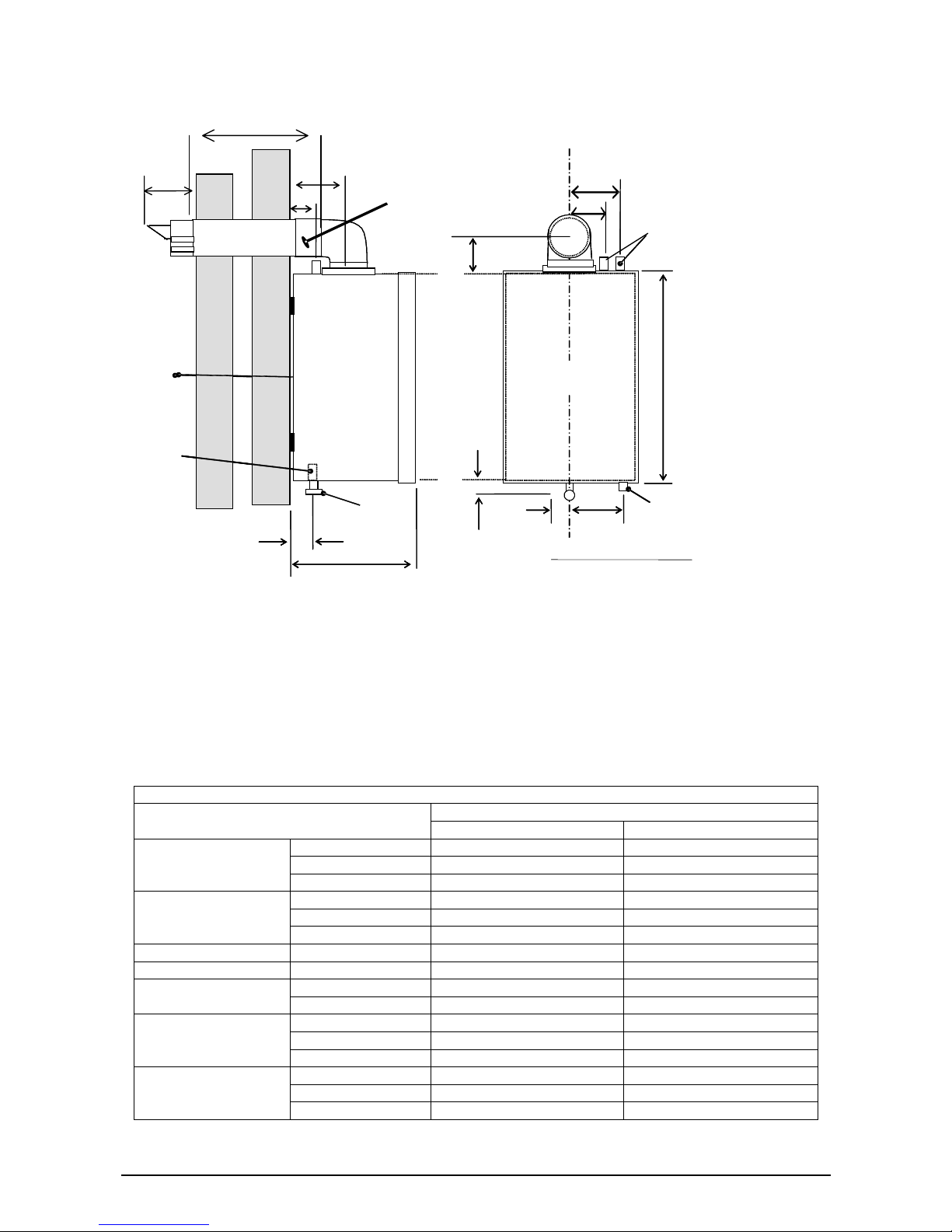
Diagram 3.2 Boiler Models GB10 and GB15
CONDENSATE
DRAIN
INSIDE WALL
FIXING FACE
BOILER
Centre Line
GAS
CONDENSATE
DRAIN
Clearances From Fixed surfaces
Top– From ‘A’ :220mm
Bottom –From ‘B’ :200mm
Sides – From ‘C’ :20mm
Front –From ‘D’ :600mm
Clearances From Fixed surfaces
:220mm
:20mm
:600mm
Top –From ‘A’
Bottom
Sides –
Front –
– From ‘B’
From ‘C’
From ‘D’
A
B
C
D
C
D
50mm
GAS
CONDENSATE
DRAIN
INSIDE WALL
FIXING FACE
F+R
70 mm
C
B
FLOW
& RETURN
BOILER
Centre Line
GAS
C
A
140mm
85mm
150mm
100mm
100mm
210mm
730mm
Cut flue terminal at
plain end to length
required allowing
40mm extra for
socket elbow joint
580mm
CONDENSATE
DRAIN
300mm
140mm
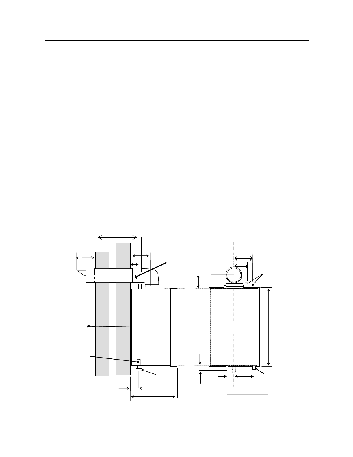
3.2. TECHNICAL DATA OF BOILERS
The main dimensions and the clearances required for the boilers are shown in diagram 3.1 for models GB30,
GB25 and GB20 and diagram 3.2 for models GB15 and GB10. The technical data of the boilers is shown in
tables 3.1 and 3.2. The boiler data badge is positioned on the inner door.
The Seasonal Efficiency Domestic Boilers UK (SEDBUK) of Gledhill Boilers (all models) is Class ‘A’. The
values used in the UK Government’s Standard Assessment Procedure (SAP) for energy rating of dwellings.
The test data from which it has been calculated has been certified by Advantica.
Table 3.1. Connection, Electrical and Weight data of the boiler
Boiler Model
GB30, GB25, GB20 GB15, GB10
Height (mm) 580 580
Width (mm) 380 380
Overall dimensions
including flue spigot
Depth (mm) 360 300
Height (mm) 1000 1000
Width (mm) 420 420
Clear space required
for installation
Depth (mm) 500 440
Weight (kg) 33 31
Water content (litres) 1.5 1
Minimum 1.0 / (0.1) 1.0 / (0.1) Working pressure
(m wg / (bar))
Maximum 30.0 / (3.0) 30.0 / (3.0)
Gas Rc1/2, (1/2in BSP) Rc1/2, (1/2in BSP)
Water 22mm copper 22mm copper
Connections
Condensate Drain 22mm Plastic pipe 22mm Plastic pipe
Electricity supply 230V, ~50Hz, Fused at 3A 230V, ~50Hz, Fused at 3A
Electrical rating 60W @230V ac 60W @230V ac
Electrical data
Internal fuse rate Main PCB 3.15AT Main PCB 3.15AT
VER: 02.3 _260505 Page:10/41
Page 11
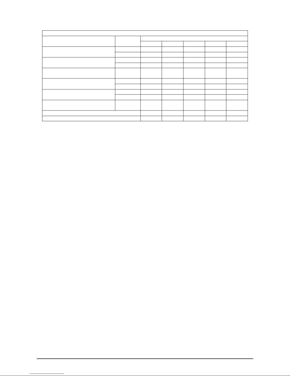
Table 3.2. Thermal, combustion and gas data
Boiler Model
Rating
GB30 GB25 GB20 GB15 GB10
Maximum 34.2 28.3 22.6 17.0 11.3
Gross heat input (kW)
Minimum 10.0 8.5 6.8 5.1 4.6
Maximum 30.8 25.5 20.4 15.3 10.2
Net heat input, Q (kW)
Minimum 9.0 7.7 6.1 4.6 4.1
Heat output, P
Non condensing (kW)
Maximum 30.2 25.0 20.0 15.0 10
Maximum 32.0 27.2 22.0 16.4 10.9 Heat output
Condensing mode (kW)
Minimum 9.8 8.4 6.6 4.9 4.5
Case off 9.6 9.6 9.6 9.7 9.6 Burner CO2 (%) at maximum rate
+0.3, -0.5
Case on 9.8 9.8 9.8 9.9 9.8
Approximate Gas rate (m3/h)
- After 10min from cold
Maximum 3.3 2.7 2.2 1.6 1.1
Off-set pressure at minimum rating (mbar) - 8.0 - 10.0 -10.0 -10.0 -9.0
Minimum water flow rate (m3/h) 1.37 1.17 0.94 0.70 0.48
3.3. GAS SUPPLY
(a) The Local Gas Supplier should be consulted at the installation planning stage in order to establish the
availability of an adequate supply of gas.
(b) An existing service pipe MUST NOT be used without prior consultations with the gas supplier.
(c) A gas meter can only be connected by the Local Gas Supplier or by his Contractor.
(d) An existing meter should be of sufficient size to carryout the maximum boiler input plus the demand of
any other installed gas appliance, (BS 6891:1988). The supply from governed meter must provide
steady inlet working pressure of 20mbar (8in wg) at the boiler. See section Technical Data for the gas
required for each specific model.
(e) The gas supply line must be purged. WARNING: before purging open all doors and windows and also
extinguish any cigarettes, pipes and any other naked lights.
(f) The complete gas installation must be tested.
3.4. ELECTRICITY SUPPLY
(a) The boiler must be permanently connected to a 230V~, 50Hz supply. This appliance MUST BE
EARTHED.
(b) All external wiring to the boiler must be in accordance with the latest I.E.E. Wiring Regulation, and any
local regulations, which may apply.
(c) There must be only one common isolator for the boiler and its control system, and it must provide
complete electrical isolation via a double pole isolator fused at 3A maximum with a contact separation of
at least 3mm in both poles.
(d) The fused spur box should be readily accessible and preferably adjacent to the appliance and it should
be identified as to its use.
(e) Alternatively the connection can be made through an unswitched shuttered socket and 3A fused 3-pin
plug both to the current issue of BS 1363 may be used, provided they are not used in a room containing
bath or shower.
(f) In the event of an electrical fault after installation of the appliance, preliminary electrical checks must be
carried out i.e. Earth Continuity, Short Circuit, Polarity, and Resistance to Earth.
VER: 02.3 _260505 Page:11/41
Page 12
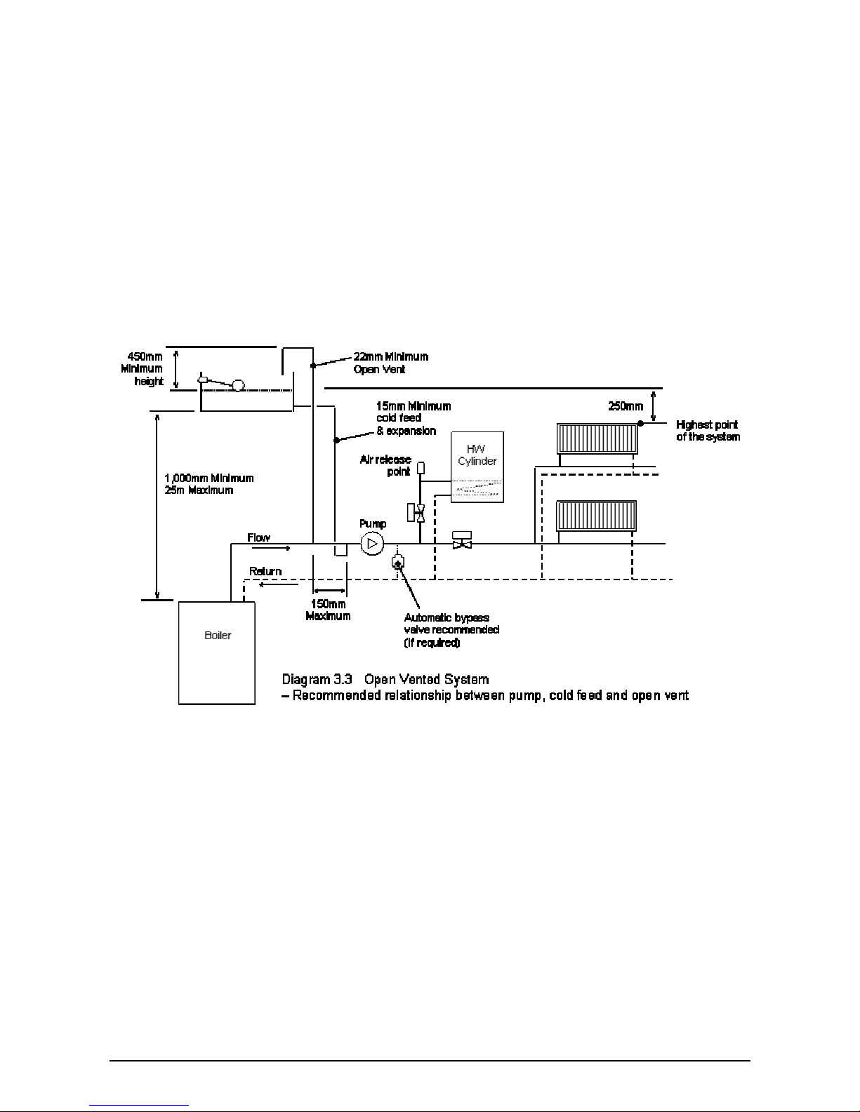
3.5. CENTRAL HEATING AND WATER SYSTEM
The Gledhill boiler is suitable for use with both vented and unvented traditional heating systems and also for
use with the thermal storage systems e.g. Gledhill BoilerMate and Gledhill SysteMate.
Plastic Pipes
When plastic pipe is to be used for the heating system, this must be suitable for the maximum pressures and
temperatures for the intended application. The class ‘S’ pipes and fittings are defined in BS 7279-1.
Some plastics are permeable to the oxygen and to prevent corrosion of system components (e.g. heat
exchanger) due to build up of oxygen, a barrier type pipe must be used i.e. pipes incorporating a polymer
barrier layer.
When plastic pipe is used, the first 2m of pipe work from the boiler (both flow and return) must be in copper.
3.5.1. Open vented heating system
(a) The open i.e. vented heating system is shown schematically in diagram 3.3. It is important that the
relative positions of the pump, cold feed and the open vent are as shown in diagram 3.3 to minimise the
chances of air ingress and pump over conditions arising.
(b) The cold feed must be 15mm minimum size. The 22mm (minimum) open vent must rise continuously
and be unrestricted.
(c) The boiler must be supplied from an unrestricted water supply taken from feed and expansion cistern
situated at a maximum height of 30 meters above the boiler.
(d) A safety valve need not be fitted to an open vented heating system.
(e) A draining tap conforming to the current issue of BS 2879, must be provided at the lowest point of the
system, which will allow the entire central heating and hot water system to be drained.
(f) The overflow/warning pipe should be in 20mm internal diameter pipe of suitable material for use in
heating systems in accordance with BS 5449 (such as copper). It should have continuous fall and
VER: 02.3 _260505 Page:12/41
Page 13
discharge in a conspicuous external position. It should not have any other pipework directly branched
into it.
(g) The water level in the F & E cistern should be at least 250mm above the highest point on the system
including the radiators
3.5.2. Sealed heating system
(a) Design Standards
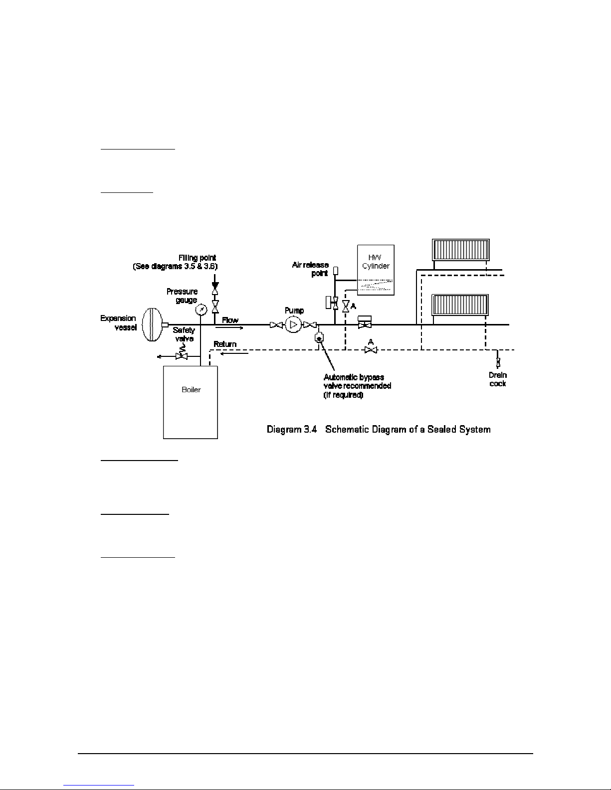
The sealed heating system is shown schematically in diagram 3.4. The sealed system installation must
comply with the appropriate requirements of current issues of BS5449, BS6759, BS6798 and BS7074.
(b)
Safety Valve
A non-adjustable safety valve must be fitted to a sealed system. It shall be pre-set with a lift pressure of
3 bar and incorporate a seating of resilient material, a test device and a connection to the drain.
(c)
Safety Valve Drain
The drain from a safety valve must be routed outside the building and positioned so that any discharge
can be seen. It must not discharge above an entrance or window or any type of public area and be clear
of any electrical fittings.
(d)
Pressure Gauge
A pressure gauge with a set pointer and covering at least 0 – 4 bar shall be fitted permanently to the
sealed system. It should be positioned where it can be seen when filling the system.
(e)
Expansion Vessel
A diaphragm type expansion vessel, conforming to the current issue of BS4814 (See also BS7074
Parts 1 and 2) must be connected to the inlet side of the circulating pump (see diagram 3.4) unless laid
down differently by the manufacturer.
The water content of the boiler is given in table 3.1.
The expansion vessel volume depends on the total water volume of the system and the initial system
design pressure as shown below in table 3.3. For any system an accurate calculation of vessel size is
given in the current issue of BS5449 and BS7074 Part 1. For example; A higher initial design charge
pressure requires a larger volume vessel.
The initial vessel charge pressure must not be less than the static head of the system, that is the height
of the highest point of the system above the expansion vessel.
VER: 02.3 _260505 Page:13/41
Page 14
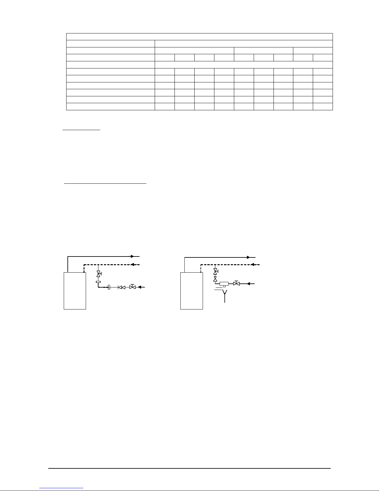
Table 3.3 Expansion vessel volume required
Safety valve setting (bar) 3.0
Vessel charge pressure (bar) 0.5 1.0 1.5
Initial system fill pressure (bar) 0.5 1.0 1.5 2.0 1.0 1.5 2.0 1.5 2.0
Total system water content (l) Expansion vessel volume (litres)
25 2.1 3.5 6.5 13.7 2.7 4.7 10.3 3.9 8.3
50 4.2 7.0 12.9 27.5 5.4 9.5 20.6 7.8 16.5
75 6.3 10.5 19.4 41.3 8.2 14.2 30.9 11.7 24.8
100 8.3 14.0 25.9 55.1 10.9 19.0 41.2 15.6 33.1
125 10.4 17.5 32.4 68.9 13.6 23.7 51.5 19.5 41.3
150 12.5 21.0 38.8 82.6 16.3 28.6 61.8 23.4 49.6
(f) Water Makeup
Provision should be made for replacing the water loss from the system using a makeup bottle mounted
in a position higher than the highest point of the system, connected through the non-return valve to the
return side of either central heating or hot water cylinder circuit.
Alternatively, provision for water makeup can be made using a filling loop, in an accessible position on
the return, or an approved CA device as discussed below.
(g)
Filling a Sealed Heating System
Provision for filling a sealed system at low level must be made and the method selected must comply
with the Water regulations. The temporary filling loop method is shown in diagram 3.5 and the CAdevice method is shown in diagram 3.6.
The CA device normally requires a pressure differential to operate and this should be taken into
account when selecting the device and the system operating pressures.
There must be no permanent connection to the mains supply, even through a non-return valve.
Boiler
Flow
Return
1. Control/ Isolating valv e
2. Do uble check valve
3. Hose unions
4. Temporary connection
Diagram 3.5 Sealed system filling method 1
1
1
23
3
4
Supply pipe
Boiler
Flow
Return
1. Control/Isolating valve
2. Type CA Backflow
Prevention devic e
3. Tundish
4. Air Gap
5. Pressure regulator
(optional)
Diagram 3.6 Sealed system filling method 2
1
1
4
Supply
pipe
2
3
5
Boiler
Flow
Return
1. Control/ Isolating valv e
2. Do uble check valve
3. Hose unions
4. Temporary connection
Diagram 3.5 Sealed system filling method 1
1
1
23
3
4
Supply pipe
Boiler
Flow
Return
1. Control/Isolating valve
2. Type CA Backflow
Prevention devic e
3. Tundish
4. Air Gap
5. Pressure regulator
(optional)
Diagram 3.6 Sealed system filling method 2
1
1
4
Supply
pipe
2
3
5
3.5.3. Gledhill BoilerMate Heating System
The Gledhill Boiler is also suitable for use with a Gledhill BoilerMate; an integrated open vented heating
system and mains pressure hot water appliance. This appliance is supplied with factory fitted and wired
system controls and equipment e.g. pumps, valves etc. The BoilerMate uses a directly heated open vented
primary store and is suitable for only vented heating systems as shown schematically in diagram 3.7. For
further details refer to Gledhill BoilerMate manual.
VER: 02.3 _260505 Page:14/41
Page 15
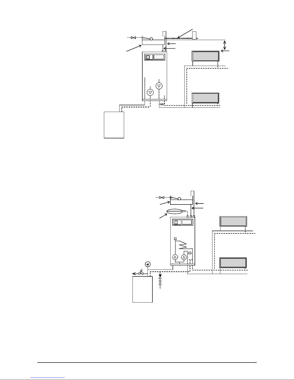
The BoilerMate acts as the
neutral point of the system
and therefore the cold feed
and open vent must be piped
to the appropriate connections
on the BoilerMate.
A draining tap conforming to
he overflow/warning pipe
The sealed central heating system
the current issue of BS 2879,
must be provided at the
lowest point of the system,
which will allow the entire
central heating and hot water
system to be drained.
T
should be in 20mm internal
diameter pipe of suitable
material for use in heating
systems in accordance with
BS 5449 (such as copper). It
should have continuous fall
and discharge in a conspicuous external position. It should not have any other pipework directly branched
into it.
Boiler
BoilerMate
250mm
Highest point
of the system
W arning/Overfl ow pi p e
Open vent
Cold feed
Mains
cold supply
•No bypass is required in the boiler circuit
•Bypass valve on heating circuit not required unless the heating
circuit incorporates 2- p ort z one valv e or TR V s on all radiator s
Diagram 3.7 Schematics of a BoilerMate heating system
Remote
F &E Cistern
Return
Flow
Boiler
BoilerMate
250mm
Highest point
of the system
W arning/Overfl ow pi p e
Open vent
Cold feed
Mains
cold supply
•No bypass is required in the boiler circuit
•Bypass valve on heating circuit not required unless the heating
circuit incorporates 2- p ort z one valv e or TR V s on all radiator s
Diagram 3.7 Schematics of a BoilerMate heating system
Remote
F &E Cistern
Return
Flow
The height of the F & E cistern above the BoilerMate should not be greater than 10m and the water level in
the F & E cistern should be at least 450mm above the highest point on the system including the radiators
3.5.4. Gledhill SysteMate Heating System
The Gledhill Boiler is also suitable for
use with a Gledhill SysteMate; an
integrated sealed heating system
and mains pressure hot water
appliance The SysteMate uses an
indirectly heated open vented hot
water only primary store. The central
heating circuit is suitable for sealed
heating systems as shown
schematically in diagram 3.8. For
further details refer to Gledhill
SysteMate manual.
When using the boiler with a
SysteMate, the pressure safety valve
must be fitted on the boiler flow pipe
adjacent to the boiler. The expansion
vessel should be fitted adjacent to
the SysteMate and connected to the
connector on the SysteMate.
design and component selection and
sizing including filling arrangements
should follow the guidelines
discussed in section 3.5.2 ‘Sealed Heating Systems’.
Boiler
SysteMate
Open vent
Cold feed
Mains
cold supply
Diagram 3.8 Schematics of a SysteMate heating system
Remote F & E
Cistern for store
Heating circuit
expansion ves s el
Return
Flow
Filling point (See diagrams 3.5 & 3.6)
Pressure gauge
Safety valve
Boiler
SysteMate
Open vent
Cold feed
Mains
cold supply
Diagram 3.8 Schematics of a SysteMate heating system
Remote F & E
Cistern for store
Heating circuit
expansion ves s el
Return
Flow
Filling point (See diagrams 3.5 & 3.6)
Pressure gauge
Safety valve
Although the heating system is sealed, the primary store in the SysteMate must be filled via a feed and
expansion cistern supplied with the appliance as shown in diagram 3.8. The height of the F & E cistern
above the BoilerMate should not be greater than 10m.
VER: 02.3 _260505 Page:15/41
Page 16
3.6. SYSTEM / BOILER PUMP
The variable duty pump should be fitted
on the flow pipe from the boiler and have
isolating valves on each side as shown
schematically in diagrams 3.3 and 3.4.
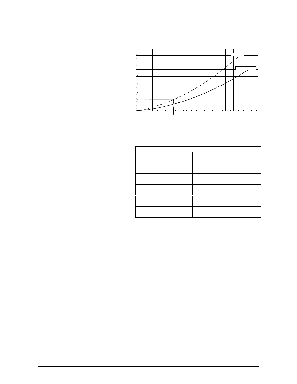
The pressure loss characteristics of the
boilers are shown in diagram 3.9. The
water flow rates and the boiler pressure
losses at 11
o
C and 20oC temperature
differences are also tabulated below
in table 3.4.
The variable duty pump should be set to
give a temperature difference of no greater
than 20
o
C between boiler flow and return to give
Diagram 3.9 Pressure l oss characteristics of the b oilers
0.0
0.5
1.0
1.5
2.0
2.5
3.0
3.5
4.0
4.5
0 100 200 300 400 500 600 700 800 900 1000 1100 1200 1300 1400 1500
Flow rate ( litres/h)
Pressure loss (mWG)
GB_10, GB_15
GB_20, GB_25, GB_30
GB-30:
30kW = 1280 l/h at 20K diff
GB-25
25kW = 1070 l/h at 20k diff
GB-20
20kW = 850 l/h at 20K diff
2.6 m
1.9 m
1.3 m
GB-15
15kW = 640 l/h at 20K diff
0.8 m
GB-10
10kW = 430 l/h at 20K dif
f
minimum flow rate through the boiler shown
in table 3.4. High resistance micro bore systems
may require a higher duty pump.
3.7. FLOW RATE
Table 3.4 Boiler pressure loss data
Boiler
Model
Temperature
difference (K)
Flow rate
(Litres)
Pressure loss
(m WG)
11 2342 6.66
GB30
20 1288 2.30
11 1951 4.79
GB25
20 1073 1.69
11 1561 3.22
GB20
20 858 1.17
11 1171 3.91
GB15
20 644 1.47
11 780 2.00
GB10
20 429 0.80
If it is necessary to alter the flow rate in a
system, the system can be fitted with a
lockable balancing valve in the main flow or
return pipes. The example is shown as a
valve ‘A’ in diagram 3.4.
The flow rate through the boiler must not be
allowed to fall below the values given in table
3.2 for the boiler model selected.
3.8. BYPASS VALVE
A bypass is not required on the central heating system unless the system controls could allow the boiler and
the pump to operate when there is no flow.
When a bypass valve has to be fitted, it must be placed at least 1.5 meters away from the boiler as shown
schematically in diagrams 3.3 and 3.4. An automatic bypass valve is recommended.
3.9. DOMESTIC HOT WATER STORAGE CYLINDER
Single feed indirect cylinders are not suitable.
The domestic hot water cylinder must be of the double feed fully indirect coil type. It must be suitable for
working at a gauge pressure of 0.35 bar above the safety valve setting.
When the storage vessel will not have vent to the atmosphere i.e. unvented cylinder is used, then the
installation must comply with the Building regulations and Local Water Company bylaws. See also the
current issues of BS5546 and BS6700.
VER: 02.3 _260505 Page:16/41
Page 17
3.10. BOILER LOCATION AND VENTILATION
3.10.1. Boiler Location
The boiler may be installed in any room although particular attention is drawn to the requirements of the
current issue of BS7671 with respect to the installation of a boiler in a room containing a bath or a shower.
Any electrical switch or boiler control using mains electricity supply should be so sited that a person using the
bath or a shower cannot touch it. The electrical provisions of the Building Standards (Scotland) Regulations
are applicable to such installations in Scotland.
These boilers are not suitable for fitting outdoors. The boiler must be mounted on a flat wall, which is
sufficiently robust to take its total weight given in table 3.1.
3.10.2. Clearances
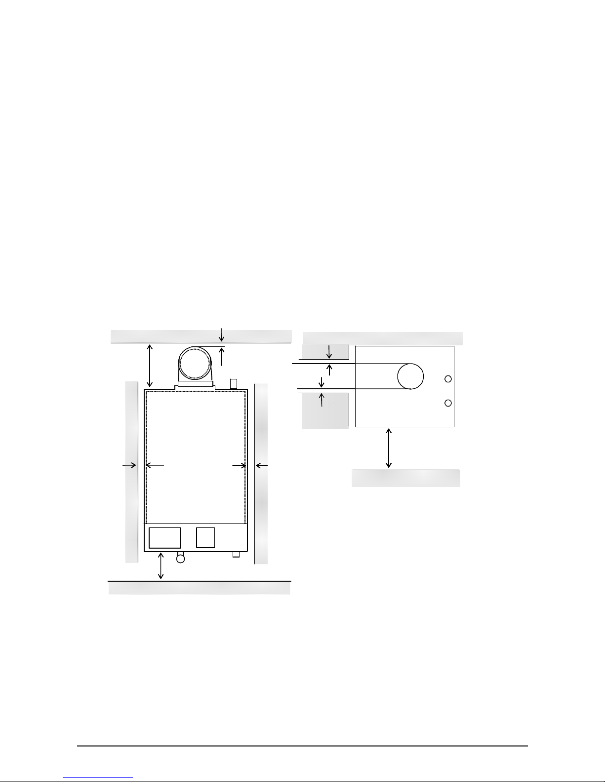
The boiler should be positioned and installed so that at least minimum clearances shown in diagram 3.10,
required for servicing and correct operation are provided. Additional clearances may be useful around the
boiler for installation and servicing.
For flue installations where external access is not practical, considerations should be given for the space
required to insert the flue internally, which may require clearances larger than those specified in diagram
3.10.
220
20 20
200
5*
Flue
Front
600
5*
5*
Diagram 3.10 Minimum clearances from
permanent fixed surfaces
All dimens i on s in m m
* Increase to 25mm clearances from combustible surfaces
220
20 20
200
5*
Flue
Front
600
5*
5*
Flue
Front
600
5*
5*
Diagram 3.10 Minimum clearances from
permanent fixed surfaces
All dimens i on s in m m
* Increase to 25mm clearances from combustible surfaces
VER: 02.3 _260505 Page:17/41
Page 18

3.10.3. Timber Frame Buildings
If the boiler is to be installed in a timber frame building, it should be fitted in accordance with the Institute of
Gas Engineers document IGE/UP/7/1998. If in doubt, ask local gas utility company or Gledhill Ltd.
3.10.4. Room ventilation
The boiler is room sealed, so when it is installed in a room or space, a permanent air vent is not required.
3.10.5. Compartment ventilation
If the boiler is installed in a compartment, a permanent air vent Is not required. However leave existing air
vents.
3.11. FLUE LOCATION AND VENTILATION
3.11.1. Flue Position and Length
The standard horizontal flue is fitted onto the top of the boiler as shown in diagrams 3.11 and 3.12. The
dimension “X” for the rear outlet flue and dimension “Y” for the side outlet flue must be measured and
compared against the standard flue supplied to check if it is suitable.
An extended flue system can be installed with the addition of extension kits (see section 3.11.3 Flue options).
The flue system must always be designed and installed to have a continuous fall towards the boiler of at
least 3
o
to allow the condensate to run to drain via the boiler.
3.11.2. Internal Flue Installation
The flue can be installed from inside the building when access to the outside wall face is not practical.
3.11.3. Flue Options
The concentric flue systems and kits available for this boiler are listed below in table 3.4. Additional
accessories and flue systems are also available for this boiler. See ‘Gledhill Boiler Flue Options Guide’ for
configurations that are available.
Table 3.4 Concentric Flue Kits and Options
Description Part No.
Standard horizontal flue kit GT461
Vertical flue terminal kit – pitched AFB001
Flat roof flue kit AFB010
Ridge terminal flue kit AFB020
VER: 02.3 _260505 Page:18/41
Page 19

The concentric flue system can be extended to a maximum equivalent length of 6.65 metres (excluding flue
terminal) after the flue elbow fitted to the appliance. This can be horizontal or vertical but the following
allowances should be made for each component fitted.
Description
Equivalent Length
2m Flue extension 2.0
1m Flue extension 1.0
0.5m Flue extension 0.5
45o Flue bend 1.5
90o Flue bend 1.9
3.11.4. Terminal Position
The minimum acceptable siting dimensions for the terminal for obstructions, other terminals and ventilation
openings are shown in Gledhill Boiler Flue Options Guide. The dimensions measured are from the edge of
the terminal.
The terminal must b exposed to the external air, allowing passage of air across it at all times.
This is a condensing boiler and therefore some pluming may occur from the flue outlet. This should be taken
in to consideration when selecting the position for the terminal.
Carports or similar extensions of roof only, or roof and one wall, require special consideration with respect to
any openings, doors, vents or windows under the roof. Care is required to protect the roof if it is made of
plastic sheeting. If the carport has a roof and two or more walls, then seek advice from the local gas supply
company before installing a boiler.
3.11.5. Terminal Guard
A terminal guard is required if a person could come into contact with the terminal or the terminal could be
subject to damage. The terminal guard is required for horizontal flue terminals below 2m above the ground
floor or accessible by the general public from the windows, balconies etc.
If a terminal guard is required, it must be positioned to provide minimum of 50mm clearance from any part of
the terminal and be central over the terminal.
A terminal guard for this boiler is shown in the Gledhill Boiler Flue Options Guide and is available from
Gledhill Ltd quoting part number GF199.
3.12. HEATING SYSTEM CONTROLS
It is recommended that a programmer and a room thermostat should control the boiler when there is a
demand for central heating and a programmer and hot water store thermostat should control the boiler when
there is a demand for water heating.
The thermostatic radiator valves may be installed; however they must not be fitted in a room where the room
thermostat is located. (
Note: All systems must have at least one radiator that is not fitted with a thermostatic
valve.
)
The heating system controls must meet the requirements of the current issue of the Building Regulations.
For further information see: -
The current issue of “Approved Document L1 – Conservation of fuel and power in dwellings”
GIL 59, 2000 : Central heating system specification (CheSS)
GPG 302, 2001: Controls for domestic central heating system and hot water. BRECSU.
VER: 02.3 _260505 Page:19/41
Page 20

3.13. CONDENSATE DRAIN
A plastic drainpipe must be fitted to the boiler to allow discharge of condensate to the suitable drain.
A copper pipe is
NOT
suitable.
Condensate should, if possible, be discharged into the internal household drainage system. If this is not
practical, discharge can be made externally into the household drainage system or a purpose designed soak
away. See section 4 for further details.
Note: Condensate trap inside the boiler casing must be manually filled with water after installing the boiler
(i.e. before the first firing) and before commissioning the system.
3.14. WATER TREATMENT
In the case of an existing installation, the system MUST be thoroughly flushed before installing the
new boiler. Power Flushing is the preferred option for existing installations because all high
efficiency boilers tend to have smaller waterways than traditional boilers. A suitable system filter
(e.g. Spirovent SV3-025-T) fitted in the boiler return is
STRONGLY recommended in existing systems.
For optimum performance after installation of the new system, the boiler and its associated central heating
system should also be flushed.
The flushing should be carried out in accordance with BS7593:1992 using cleaner such as Sentinel X300 or
X400 or Fernox Superfloc.
For long-term corrosion protection, after flushing, an inhibitor suitable for stainless steel heat exchangers
should be used. Refer to the current issue of BS5449 and BS7593 on the use of inhibitors in central heating
systems. The examples are Sentinel X100 and Fernox.
VER: 02.3 _260505 Page:20/41
Page 21

4. BOILER INSTALLATION
4.1. INSTALLATION PREPARATION
Unpacking Of Boiler
Important:
With regards to the Manual Handling Operations, 1992 Regulations, the following lift operation
exceeds the recommended weight for one man lift.
Stand the boiler carton upright.
Cut and remove the securing straps and lift off the carton sleeve. Place aside any loose components until
required.
Carefully lay the boiler on its back, remove the two front casing panel-securing screws and lift off the panel
from the two retaining lugs.
Remove the two inner casing panel-securing screws at the bottom of the front panel, and then lift off the two
retaining lugs.
4.1.1. Wall Template
A wall template is supplied with the boiler. This should be used to mark the boiler fixings and flue outlets and
for checking the minimum clearances required.
4.1.2. Flue Hole Cutting
The
standard horizontal flue
is designed with an internal fall of 35mm/metre towards the boiler for disposal
of condensate. If the standard flue length alone is being used then the flue hole of diameter 105mm can be
cut in the position marked on the wall template.
For
standard side flues
the horizontal flue centre line on the wall template should be extended to the side
wall, and the vertical centre of the flue hole marked at 176mm from the back wall.
For installations with external access, a 105mm diameter core drill can be used.
For installations with internal access only a 125mm diameter core drill should be used.
When using extension pipes with the horizontal rear flue, a core drill size of 125mm should be used to allow
the extension pieces to slope at 35mm/metre (2.5°) towards the boiler.
For
extended side flues
, the flue hole centre should be determined by extending the dashed inclined line on
the template to the side wall. This dashed line is drawn at 35mm/metre (2.5°) rise from the boiler. Where
this line reaches the side wall, a horizontal line should be marked. The vertical centre line of the flue should
then be marked at 176mm from the back wall, see diagram 5.3.
To allow for the flue passing through the wall at this angle a 125mm hole should be drilled irrespective of
internal or external installation.
If necessary remove the wall template whilst drilling the flue hole.
4.2. Hanging Bracket Fixing
If previously removed, reposition the wall template over the flue hole and mark the position of the fixing holes
for the hanging bracket.
Mark and drill the fixing holes and secure the hanging bracket.
VER: 02.3 _260505 Page:21/41
Page 22

4.3. BOILER FIXING
Important:
With regards to the Manual Handling Operations, 1992 Regulations, the following lift operation
exceeds the recommended weight for a one man lift.
Having previously secured the hanging bracket to the wall, lift the boiler into position in the following
manner:Lean the top of the boiler slightly to the wall and position just above the hanging bracket. Allow the boiler to
slowly move downwards until engaged in the hanging bracket.
4.4. CONNECTIONS
4.4.1. Gas Connection
Before connection check the supply of local gas.
The gas supply can be connected from below.
4.4.2. Water Connections
Provision is made for the water connections to be made from above the boiler.
The position is shown on the wall template.
Flush out the domestic hot water and the heating systems before connecting to the boiler.
4.4.3. Condensate Drain Connection
Before fitting the condensate drainpipe, remove and fill the condensate trap with water and refit to the
appliance.
The condensate will be slightly acidic and the condensate pipe should be run in a high temperature plastic
drainpipe material (e.g. PP, UPVC etc). Copper tube
MUST NOT
be used and ‘push fit’ overflow pipe
MUST
NOT
be used.
Internal pipe work should have a bore diameter no smaller than 20mm.
The external pipe work should be kept to a minimum, and have a bore diameter no smaller than 32mm.
The pipe should not have any upward pipe runs and must fall at least 2.5º (1:20) throughout its length
towards the discharge point.
It is strongly recommended that the condensate pipe
should be run internally to the house soil or vent stack or to
a waste pipe.
Alternatively the condensate may be discharged into a
rainwater system, external gully or a purpose-built soak
away. Any local building control authority requirements
must be complied with.
It is recommended that the pipe should not be installed
externally but if it is it should be insulated and terminated
below the grating level of the gully or at least 50mm above
the soak away to minimise the effects of freezing.
VER: 02.3 _260505 Page:22/41
Page 23
5. ELECTRICAL WIRING
5.1
GENERAL
Warning:
The boiler must be permanently connected to a 230V~, 50Hz supply. This appliance MUST BE
EARTHED.
All external wiring to the boiler must be in accordance with the latest I.E.E. Wiring Regulation, and any local
regulations which may apply
There must be only one common isolator for the boiler and its
control system, and it must provide complete electrical
isolation via a double pole isolator fused at 3A maximum with
a contact separation of at least 3mm in both poles.
The fused spur box should be readily accessible and
preferably adjacent to the appliance and it should be
identified as to its use.
Alternatively the connection can be made through an
unswitched shuttered socket and 3A fused 3-pin plug both to
the current issue of BS 1363 may be used, provided they are
not used in a room containing bath or shower.
Do not interrupt the mains supply to the boiler with a time
switch or a programmer.
In the event of an electrical fault after installation of the
appliance, preliminary electrical checks must be carried out i.e. Earth Continuity, Short Circuit, Polarity, and
Resistance to Earth.
L
SL
_
B
E
N
E
L_
PN_P
Mains input
cable
Pump output
cable
Cable clamp
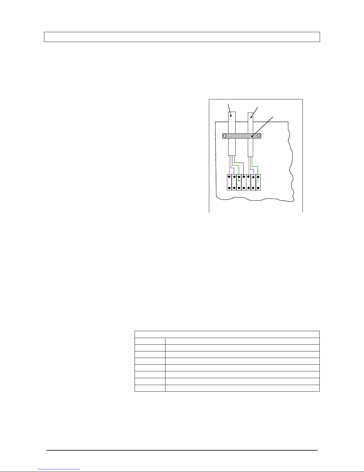
Diagram 5.2 Wiring terminals and cable connections
Wiring terminals
See table 5.1
L
SL
_
B
E
N
E
L_
PN_P
Mains input
cable
Pump output
cable
Diagram 5.2 Wiring terminals and cable connections
Wiring terminals
See table 5.1
Electrical components in this appliance have been tested to meet the requirements of the BEAB.
5.2
EXTERNAL CONTROLS (Mains Voltage: 230V, 50Hz)
(a) The Gledhill boilers are fitted with wiring terminals inside the control panel as shown in diagram 5.1.
The access to these terminals is gained by first removing the front cover by removing the two screws at
the bottom (front) and then opening the hinged control panel by first unscrewing the retaining screw.
(b) Observe all terminal markings and colour codes as shown in diagrams 5.1 – 5.4 and table 5.1. Ensure
that all flexible cords are routed through the strain relief cable glands and clamps located on the bottom
of the boiler and in the control/wiring panel.
(c) Ensure that the separate external mains supply, control and pump cables are fed to the boiler. Connect
both the mains supply and
switched live supply from
the external controls (e.g.
room thermostat,
BoilerMate) into the marked
terminals as shown in
diagrams 5.2, 5.3 and 5.4.
For the conventional
heating systems also
connect the pump supply
into the marked pump
terminals as shown in diagrams 5.2 and 5.3.
Table 5.1 Description of boiler wiring terminals
Terminal Description
L Mains (L) supply – 230V ~ 6A rated cable (0.75mm2)
N Mains (N) supply – 230V ~ 6A rated cable (0.75mm2)
E Mains (GND, E) supply – 0V ~ 6A rated cable (0.75mm2)
SL-B Switched Live (L) supply – 230V~ 6A rated cable (0.75mm2)
L-P Supply to pump (L) – 230V~ 3A rated cable (0.75mm2)
N-P Supply to pump (N) – 230V~ 3A rated cable (0.75mm2)
E Supply to pump (GND, E) – 0V ~ 6A rated cable (0.75mm2)
(d) The controller in this boiler is phase sensitive. Therefore if mains supply ‘Live’ and ‘Neutral’ are
reversed, the controller will not work and the error message will be displayed.
VER: 02.3 _260505 Page:23/41
Page 24
(e)
Electrical Connection Testing
Carryout preliminary electrical checks below after wiring before switching on the supply: -
The insulation resistance to earth of mains cables.
Test the earth continuity and short circuit of cables.
Test the polarity of the mains.
5.2.01 Wiring – Conventional Systems
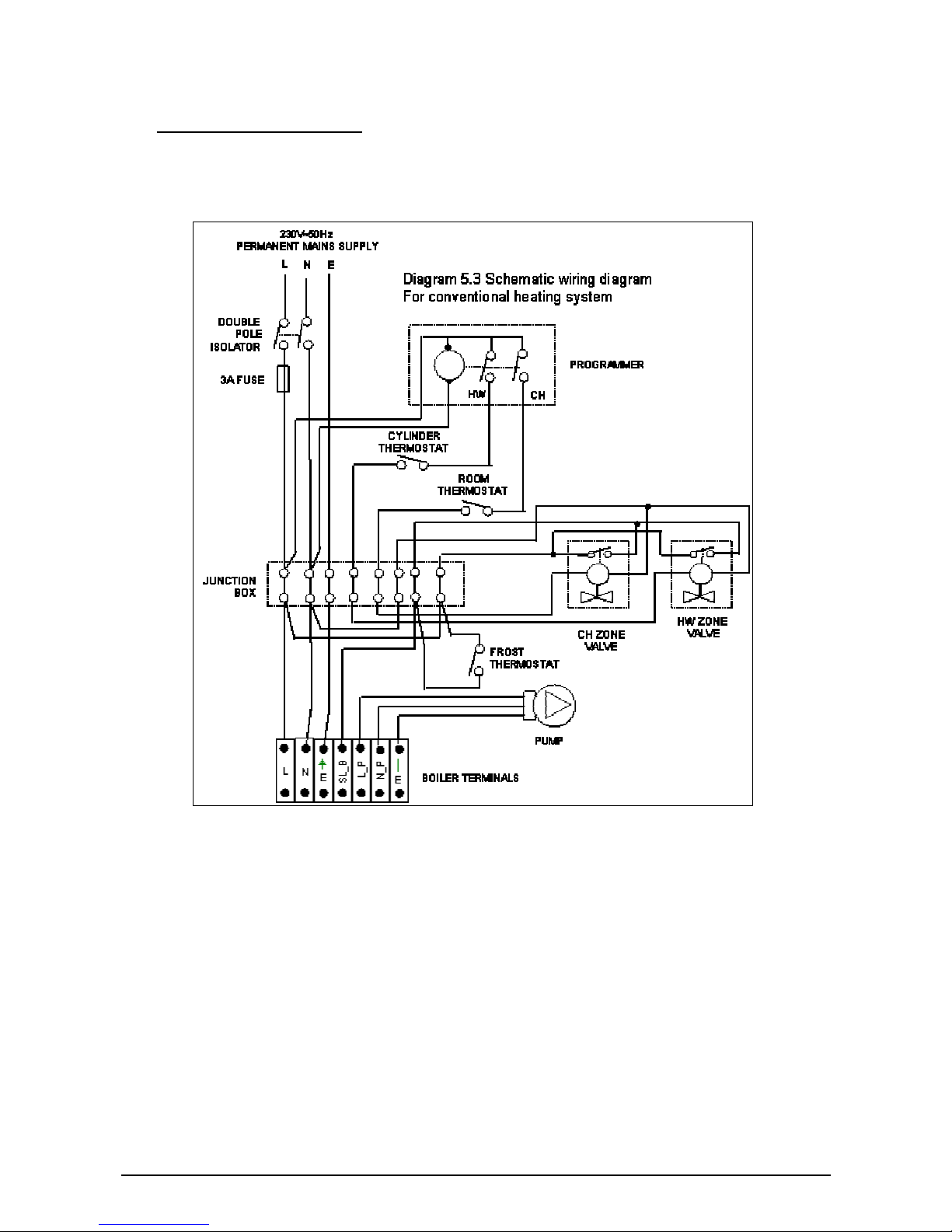
(a) The schematic wiring diagram of conventional heating system with vented or unvented domestic hot
water storage is shown in figure 5.3. Although diagram shows 2 zone valves, the boiler is equally
suitable for systems designed with a 3-port valve.
(b) When designing and planning the system wiring, take into account recommendations of control
manufacturers and requirements of controls selected.
(c) The boiler incorporates pump overrun control logic. Therefore only feed the system pump from the
boiler wiring terminals marked ‘L-P’, ‘N-P’, and ‘E’ (see diagrams 5.2 and 5.3) and not from a separate
electricity supply.
(d) The boiler has integrated frost protection control logic to prevent the boiler from freezing. This will be
automatically activated if the temperature inside the boiler drops below 5
o
C provided the electricity and
the gas supplies to the boiler are not switched off. If frost protection is required for other parts of the
heating circuit, then a 230Vac frost thermostat should be wired as shown in diagram 5.3.
VER: 02.3 _260505 Page:24/41
Page 25
(e) After completing the wiring carryout electrical testing (section 5.2 (e)) and refit the appliance control
panel and front cover. Please ensure that the ‘Benchmark’ logbook is completed and left with the user.
5.2.2. Wiring – BoilerMate/SysteMate
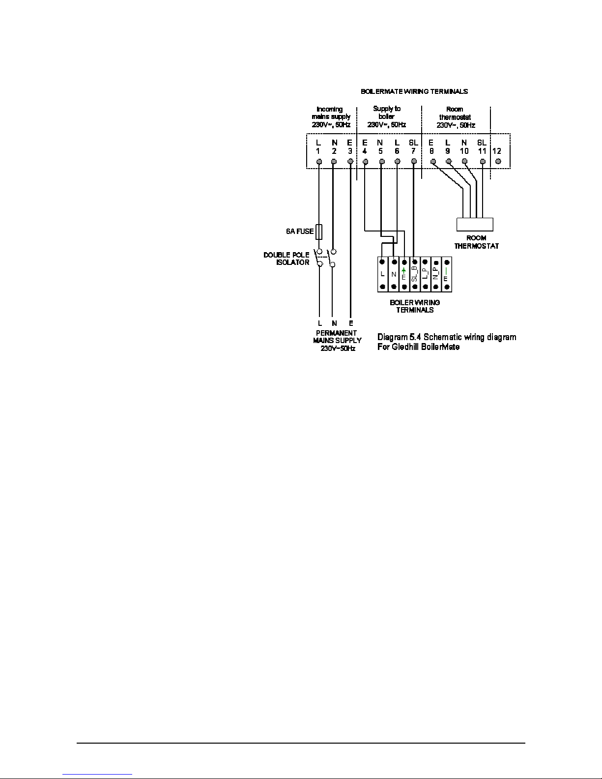
(a) The schematic wiring diagram of
Gledhill BoilerMate based heating
and hot water system is shown in
figure 5.4. The wiring details of a
SysteMate are similar.
(b) When a boiler is coupled to a
BoilerMate (or a SysteMate), then
the mains electricity supply from the
isolator must be to the BoilerMate
and a boiler should be supplied from
the BoilerMate via a secondary 3
pole isolator as shown in diagram
5.4.
(c) When designing and planning the
system wiring, take into account
recommendations of control
manufacturers and requirements of
controls e.g. programmer and room
thermostat selected.
(d) The boiler pump overrun is provided
by the BoilerMate controller.
(e) The frost protection control logic of the boiler must be disabled by inserting a jumper on pins 1&2 of
connector J3 on the main PCB (see section 8). If frost protection is required for any part of the heating
circuit, then a 230Vac frost thermostat should be wired as shown in the BoilerMate or a SysteMate
manual.
(f) After completing the wiring carryout electrical testing (section 5.2 (e)) and refit the appliance control
panel and front cover. Please ensure that the ‘Benchmark’ logbook is completed and left with the user.
VER: 02.3 _260505 Page:25/41
Page 26

6. COMMISSIONING
6.1. General
Commissioning should be carried out by a competent person in accordance with the current issue of
BS6798. Make sure that the system has been thoroughly flushed out with cold water. Refill the system with
water, making sure that all the air is properly vented from the system. Before operating the boiler check that
all external controls are calling for heat.
With a sealed system fill the system until the pressure gauge registers the recommended pressure. Clear
any air locks and check for leaks. Check the operation of the safety valve, preferably by allowing the water
pressure to rise until the valve lifts. This should be within
±
0.14 bar of the preset pressure. Where this is
not possible a manual check should be carried out. The system pressure should then be reduced to the
initial design pressure.
6.2. Initial Lighting
Isolate the boiler from the mains electrical supply. Test for gas soundness and purge any air from the gas
supply. The boiler lighting procedure operates automatically once the switch on the appliance is in the ON
position (indicated by flame symbol) and any external controls are calling. The dot D1 will begin to flash to
indicate that the controller is active. When the burner is lit, the dot D1 will be on constant and the digital
display will indicate the boiler flow temperature. If the boiler fails to light it will attempt to ignite 5 times before
showing ignition lockout, initially this may be due to air in the gas supply line.
After the boiler has fired allow it to warm up the system and purge any remaining air from the system, the
appliance will continue to fire until the user controls are satisfied.
6.3. Testing – Gas
The gas rate can be checked using the gas meter and a stopwatch after the burner has been running for 10
minutes. Before a gas rate check is made make sure all other gas burning appliances are turned off.
As a guide the approximate gas rates are: GB30 3.3 m
3
/h at maximum fan speed
GB25 2.7 m
3
/h at maximum fan speed
GB20 2.2 m
3
/h at maximum fan speed
GB15 1.6 m
3
/h at maximum fan speed
GB10 1.1 m
3
/h at maximum fan speed
IMPORTANT
The gas valve and the Venturi are factory set and sealed. These should not need any adjustment and
MUST NOT be tampered with. However, check that a supply pressure of 20mbar is available at the
boiler when it is firing at full rate.
6.4. Testing – Heating System
Check that all controls are calling for heat, fully open all radiator valves and allow the heating system to heat
up. Balance the radiators as requires giving the required differential across the heating system and set the
bypass. Turn off all user radiator valves that can be turned off and check that the maximum differential
achievable across the flow and return is less than 20
o
C.
Allow the system to achieve full temperature and then switch off and isolate the appliance. Drain the system
whilst still hot from the lowest part of the system ensuring all parts of the system is emptied. Fill and vent the
system as described previously.
VER: 02.3 _260505 Page:26/41
Page 27

6.5. Testing – User Controls
Check all external time and temperature controls are fully operational and give the expected response to
user operation. Check the operations of the on/off and reset switch on the boiler.
When the burner is lit, the dot D1 will be on constant and the digital display will indicate the boiler flow
temperature.
A fault is indicated by flashing dot ‘D2’ and the fault code is displayed on the digital display. To reset press
‘Set/Reset’ button S1.
6.6. Frost Protection
The boiler has frost protection built into its operation programme but requires the gas and electricity to be
switched on. This programme operates the burner and system pump if the temperature inside the boiler falls
below 4
o
C. This device is designed to protect the boiler and any other exposed area of the system should be
protected separately by a frost thermostat.
6.7. Instruct the User
A demonstration of the lighting procedure and advise of safe and efficient operation should be given to the
user. The use and operation of the heating system controls should also be demonstrated to the user along
with the use and maintenance of any other equipment e.g. scale reducers that may be fitted to the system.
Advise that to continue with safe and efficient operation of the boiler it is recommended that the boiler is
checked and serviced at a regular interval of a minimum of once a year.
Advise that like all condensing boilers this appliance will produce a plume from the flue terminal in cold
weather and this is normal for a high efficiency boiler.
Advise of the user of the precautions necessary to prevent damage by frost and freezing conditions if the
system is out of use. Along with a need to keep the electrical and gas supplies switched on to enable the
automatic frost protection to work.
Draw attention to the law that any servicing should be carried out only by a competent person and if
applicable to the current issue of the Gas Safety (Installation & Use) Regulations, Section 35, which imposes
a duty of care on all persons who let out any property containing a gas appliance.
VER: 02.3 _260505 Page:27/41
Page 28

7. SERVICING
7.1. General
IMPORTANT
DO NOT TAMPER WITH THE APPLIANCE OR BREAK ANY SEALS ON THE PRE-SET CONTROLS
(BURNER OFFSET PRESSURE AND THROTTLE SETTINGS) OF THE APPLIANCE. IF IT IS
NECESSARY TO REPLACE ANY OF SEALED PARTS, THEN THESE SHOULD BE REPLACED BY
FACTORY SET AND SEALED PARTS SUPPLIED BY GLEDHILL LTD
Measurement of the products of combustion can be achieved by connection of a probe to the
combustion analyser test point on the flue elbow connecting the boiler to the flue system.
Before commencing with a service or replacement of parts the boiler should be isolated from the
electrical supply and the gas supply should be turned off at the gas isolation valve.
All routine service requirements can be achieved by the removal of the front cover, inner casing panel
and lowercasing panel as described in section General 9.1. Unless stated otherwise parts are
replaced in the reverse order of removal. Servicing should always include the removal of any debris
from the condensate trap. After completing any servicing of gas carrying components ALWAYS test
for gas soundness and carry out a functional test of the controls.
7.2. Spark & Flame sensing electrodes
For access refer to section General 9.1
Remove the spark plug style connector from the electrode and earth lead in the case of the spark
electrode. Remove the two retaining screws with a Torx T20 driver, carefully withdraw the electrode
from the combustion chamber. Inspect the tips for damage, clean away any debris and check the
spark gap is 3.5-4.5mm. Check the electrode gasket for signs of damage and replace if necessary.
7.3. Burner
For access refer to section General 9.1 & 9.1.1
Clean the burner with a soft brush taking great care not to damage the front insulation. DO NOT use
wire or sharp instruments to clean the holes in the burner. Inspect the burner for any signs of damage.
Removal of the burner is not necessary during a normal service.
NOTE: IF THE BURNER HAS TO BE REMOVED IT WILL REQUIRE A NEW GASKET WHEN
REFITTED.
When replacing the assembly ensure the sealing grommet is correctly fitted.
7.4. Combustion Chamber and Heat Exchanger
For access refer to section General 9.1 & 9.1.1
Remove loose debris from the combustion chamber using a soft brush and vacuum cleaner. Carefully
flush any remaining debris by spraying water through to the condensate trap (ensuring the water is
kept away from electrical components).
7.5. Condensate Drain
For access refer to section General 9.1
Remove the yellow cap from the bottom of the trap and remove any solids found. Remove the flexible
condense pipe connection from the bottom of the heat exchanger and the drain connection
downstream of the condense trap. Remove the condensate trap and flush water through the trap to
remove any remaining solids. Reassemble the trap and connection ensuring a watertight seal is
achieved.
VER: 02.3 _260505 Page:28/41
Page 29

7.6. Inner Casing Panel Seal Check
For access refer to section General 9.1
Check the condition of the seal, replace as required. To replace remove the old seal, thoroughly
clean the casing surfaces. Fit the new seal, it is supplied the correct length.
7.7. Combustion Check
Once the appliance has been reassembled (apart from the front and inner panel) connect a CO2
combustion analyser to the test point on the flue elbow.
VER: 02.3 _260505 Page:29/41
Page 30
8. FAULT FINDING
8.1. CONTROLLER DISPLAY
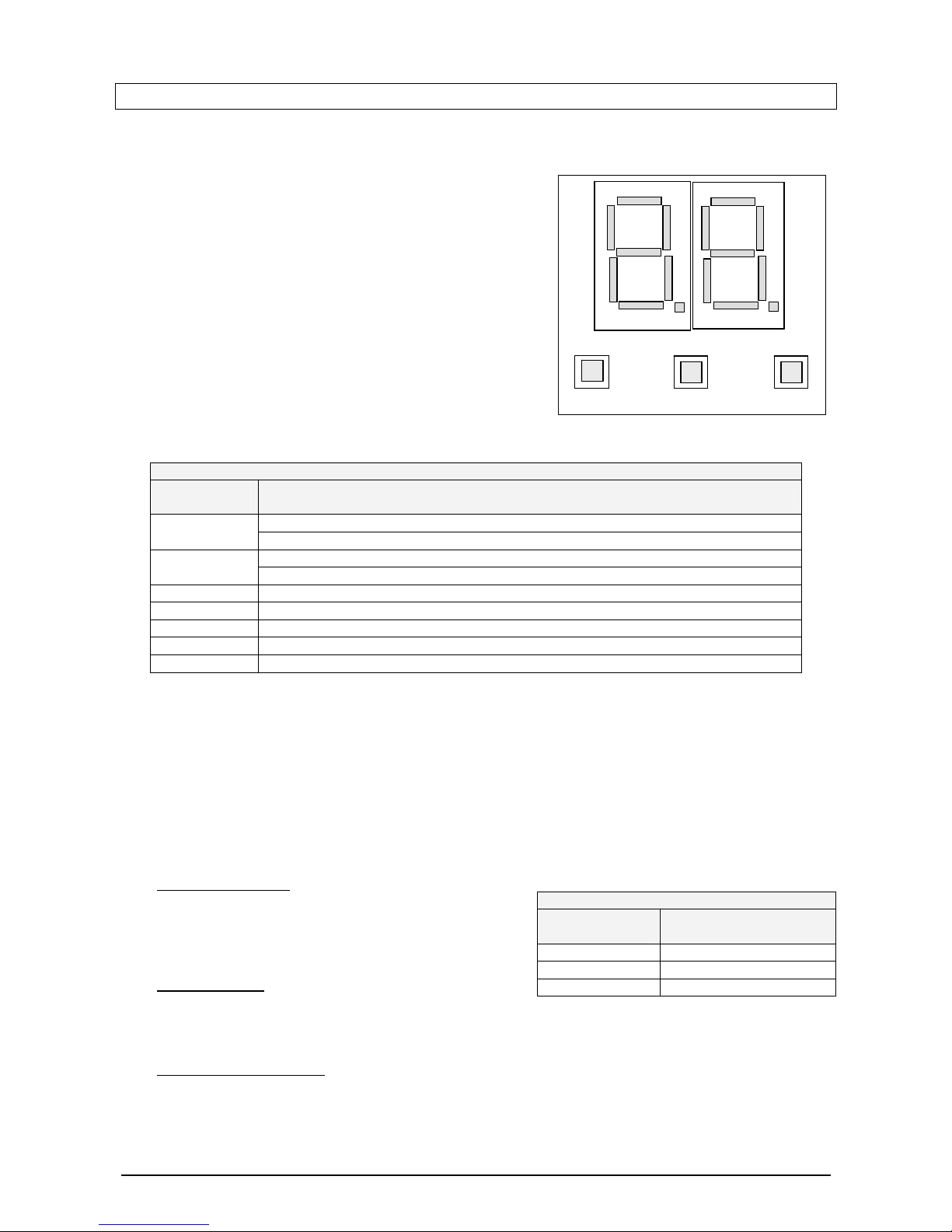
The controller display unit is equipped with a two digit, 7
segment display and three push buttons as shown schematically
shown in figure 8.1. The display shows the system status and
can be used to display diagnostic information.
S3
S2
Set/Reset
-
+
S1
D1
D2
a
b
c
j
i
h
d
e
f
g
k
l
m
n
Diagram 8.1 Controller display
S3
S2
Set/Reset
-
+
S1
D1
D2
a
b
c
j
i
h
d
e
f
g
k
l
m
n
S3
S2
Set/Reset
-
+
S1
D1
D2
a
b
c
j
i
h
d
e
f
g
k
l
m
n
Diagram 8.1 Controller display
The push buttons can be used to enter the parameter menu and
to change the parameters. The push button S1 is also used to
clear locking errors and reset the controller.
8.1.1. Normal Level-1 (Default) Operation
The information display in normal user (Level-1) mode is
described below in table 8.1. If no input is detected when the
display is in level 2 or level 3 mode for a period of about 20
seconds, it will automatically revert back to default mode.
Table 8.1: Level-1 Display description
Display
segment
Description
On/Off : Indicates that the controller is active and in standby mode
D1
On : Indicates ionisation i.e. burner is on
On/Off : Lockout error – Requires reset
D2
On : Blocking error detected
b Controller is initialising
h Overheat safety trip
a, d, b & f ‘F’ – Frost program active
i Heat demand on
j Pump on
8.1.2. Level-2 Display Operations
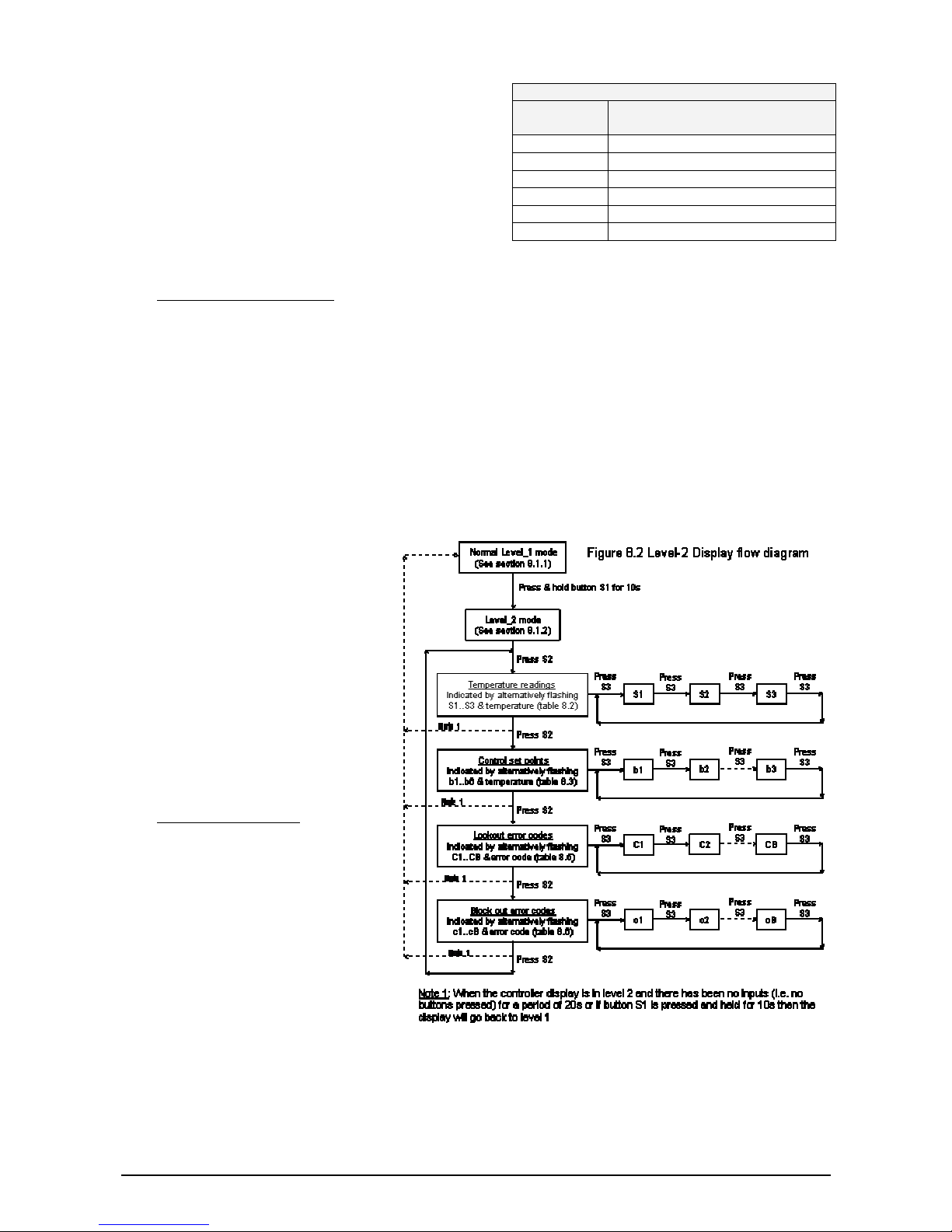
The level-2 is used to display the temperatures, set points and errors. The information flow diagram for level2 is shown below in diagram 8.2. Push buttons S2 and S3 are used to select the parameters vertically and
horizontally respectively.
The level-2 is accessed by pressing and holding push button S1 for minimum of 10s. The controller display
will go back to level 1 if either there has been no input (i.e. buttons pressed) for 30s or if push button S1 is
pressed and held for 10s.
(a)
Temperature display
The temperature of the sensor selected is displayed by
alternatively flashing the sensor number and the temperature
measured by it or ‘Er’ if it is in error. The sensor definition is
shown in table 8.2.
(b)
Set point display
The selected set point is displayed by alternatively flashing
the set point number (b1...b6) and the corresponding set point. The definition of set points is listed in table
8.3.
Table 8.2: Sensor description
Sensor
number
Description
S1 Boiler flow
S2 Boiler return
S3 Flue gas
(c)
Lockout fault code display
In this mode the lockout fault codes are displayed. The button S2 is used to select this mode and the button
S3 is used to cycle between the stored faults. Fault code reading is displayed by alternatively flashing the
fault number and the internal error number.
VER: 02.3 _260505 Page:30/41
Page 31
There are 16 fault codes stored in order of occurrence.
The fault code ‘C0’ is the current or last fault code and the
fault code ‘CF’ is that happened the longest time ago.
Table 8.3: Set point description
Set point
number
Description
b1 blr_flow_setpoint, (S1)
b2 blr_flow_hysterese, (S1)
b3 blr_return_setpoint, (S2)
b4 blr_return_hysterese, (S2)
b5 max_flue_setpoint, (S3)
b6 blr_flow_overheat
When no fault is stored at the displayed fault number, an
‘FF’ is displayed. It is also possible that ‘EE’ is displayed
for an internal error number. This means that the
controller is busy reading the memory. The lockout error
codes are listed in table 8.5.
The locking errors can be cleared by pressing the reset button S1.
(d)
Block out fault code display
In this mode the block out fault codes can be displayed. The button S2 is used to select this mode and the
button S3 is used to cycle between the stored faults. Fault code reading is displayed by alternatively flashing
the fault number and the internal error number.
There are 16 fault codes stored in order of occurrence. The fault code ‘c0’ is the current or last fault code and
the fault code ‘cF’ is that happened the longest time ago.
When no fault is stored at the displayed fault number, an ‘FF’ is displayed. It is also possible that ‘EE’ is
displayed for an internal error number. This means that the controller is busy reading the memory. The block
out error codes are listed in table 8.6.
The error will be reset when fault is cleared. To reset some internal errors switch power off, wait 10 seconds
and switch power on again.
8.1.3. Level - 3 Display Operations
The level 3 is used for setting the boiler
flow temperature and selecting the
boiler model. This level is intended for
use by the installer/service engineer.
The level 3 setting menu is accessed by
simultaneously pressing and holding the
push buttons S2 and S3 for at least 10
seconds.
The setting level is indicated by flashing
‘0’ on the on LH digit of the display and
solid ‘0’ on the RH digit of the display.
(a) Boiler model selection
The parameter to be set is selected by
using buttons S2 or S3. The display is
cycled using these buttons until ‘B’
flashes on the LH digit and the current
boiler ID (1…5) is shown on RH digit.
The boiler models and their ID codes
are listed in table 8.4. To change the
boiler ID press and hold button S1 until
RH digit starts to flash. Select the boiler
ID using buttons S2 or S3. Press and
hold button S1 to confirm the selected
boiler ID.
If the selected boiler ID matches the ID resistor fitted, the RH digit will stop flashing. The controller will use
the boiler model specific data (e.g. fan speeds) for future control actions.
VER: 02.3 _260505 Page:31/41
Page 32
If the selected boiler ID does not match the ID resistor fitted, the RH digit will display flashing ‘E’. The T_ID
values corresponding to the ID resistors are shown on PC serial screen.
If the controller does not sense any further inputs from buttons S1, S2 or S3 for a period of 20s, it will revert
back to normal display.
Table 8.4. ID Data of boiler models
Model Boiler ID ID resistor
GB10 B1 1K, (T_ID=100)
GB15 B2 1K5, (T_ID=66)
GB20 B3 2K2, (T_ID=73)
GB25 B4 3K3, (T_ID=61)
GB30 B5 4K7, (T_ID=51)
(b) Boiler flow temperature setting
The parameter to be set is selected by using buttons S2 or
S3. The display is cycled using these buttons until ‘b’ (on the
LH digit) and the current maximum boiler flow temperature
setting (e.g. 77) starts to flash alternatively
To change the maximum boiler flow temperature setting, press and hold button S1 until digits stop flashing
and only the current set temperature is displayed.
Change the boiler flow set point using buttons S2 or S3. Press and hold button S1 to confirm the setting until
‘b’ (on the LH digit) and the current maximum boiler flow temperature setting (e.g. 77) starts to flash
alternatively.
If the controller does not sense any further inputs from buttons S1, S2 or S3 for a period of 20s, it will revert
back to normal display.
8.2. ERROR/FAULT CODES
The errors are divided into two groups; blocking errors which will disappear when error is cleared and the
non volatile locking errors which can only be reset by pressing the reset button.
The locking errors are shown in table 8.5 and these will be indicated with ‘C’ prior to the error number. The
blocking errors are shown in table 8.6 and these will be indicated with ‘E’ prior to the error number.
Table 8.5 Lockout error codes
‘C’
code
Error Int
no
Description
1 IGN_ERROR 1 No flame detected after 3 ignition attempts
2 TOO_MANY_FLAME_FAILURES 24 Three flame losses within one demand for heat
4 GV_RELAY_ERROR 5 Gas valve relay is not opening or closing correctly
5 SAFETY_RELAY_ERROR 6 Safety is not opening or closing correctly
8 IGNIT_RELAY_ERROR 7 Ignition relay is not opening or closing correctly
9 RAM_ERROR 9 RAM check in processor is not correct
10 E2PROM_ERROR 12 E2Prom contents corrupt
12 WRONG_EPROM_SIGNATURE 10 E2Prom contents does not correspond with main
software
13 STATE_ERROR 13 Internal software error
14 ROM_ERROR 14 Internal software error
15 15MS_XRL_ERROR 16 Internal software error
16 20MS_XRL_ERROR 22 Internal software error
18 STACK_ERROR 19 Internal software error
19 FLAME_OUT_TOO_LATE_ERROR 20 After closing the gas valve the flame was detected
for period longer than 10 seconds
20 FLAME_ERROR_1 21 Flame detected prior to opening the gas valve
32 41MS_ERROR_EROR 23 Internal software error
33 FAN_ERROR 8 Fan does not run on correct speed
VER: 02.3 _260505 Page:32/41
Page 33

Table 8.6 Blocking error codes
‘c’
code
Error Int
no
Description
1 T_FLOW_OPEN 48 Flow sensor, S1, open
2 T_RETURN_OPEN 47 Return sensor, S2, open
8 T_FLUE_OPEN 51 Flue sensor, S3, open
11 T_FLOW_SHORTED 56 Flow sensor, S1, shorted
12 T_RETURN_SHORTED 55 Return sensor, S2, shorted
18 T_FLUE_SHORTED 59 Flue sensor, S3, shorted
13 REFHI_TOO_LO_ERROR 28 Temperature measurement incorrect
14 REFHI_TOO_HI_ERROR 29 Temperature measurement incorrect
15 REFLO_TOO_LO_ERROR 30 Temperature measurement incorrect
16 REFLO_TOO_HI_ERROR 31 Temperature measurement incorrect
19 E2PROM_READ_ERROR 0 Not able to read e2prom contents
20 FLAME_ERROR_2 33 Flame detected with a closed gas valve
21 PHASE_ERROR 41 Mains supply live and neutral are reversed
22 50HZ_ERROR 42 Mains frequency is not 50Hz
42 WD_COMUNICATION_ERROR 44 problems with communicating with watchdog
51 RESET_BUTTON_ERROR 65 Reset button pressed to many times in a short time
8.3. SERIAL SOFTWARE
In order to check the control and to set the parameters in its E2PROM, serial software is provided. To use
this software a windows PC with serial port (COMP port) or a USB port is needed.
8.4. INTERNAL WIRING DIAGRAM
The appliance wiring diagram is shown in diagram 8.3. Ensure that wiring details are followed when a PCAB,
wiring harness or components are changed.
VER: 02.3 _260505 Page:33/41
Page 34
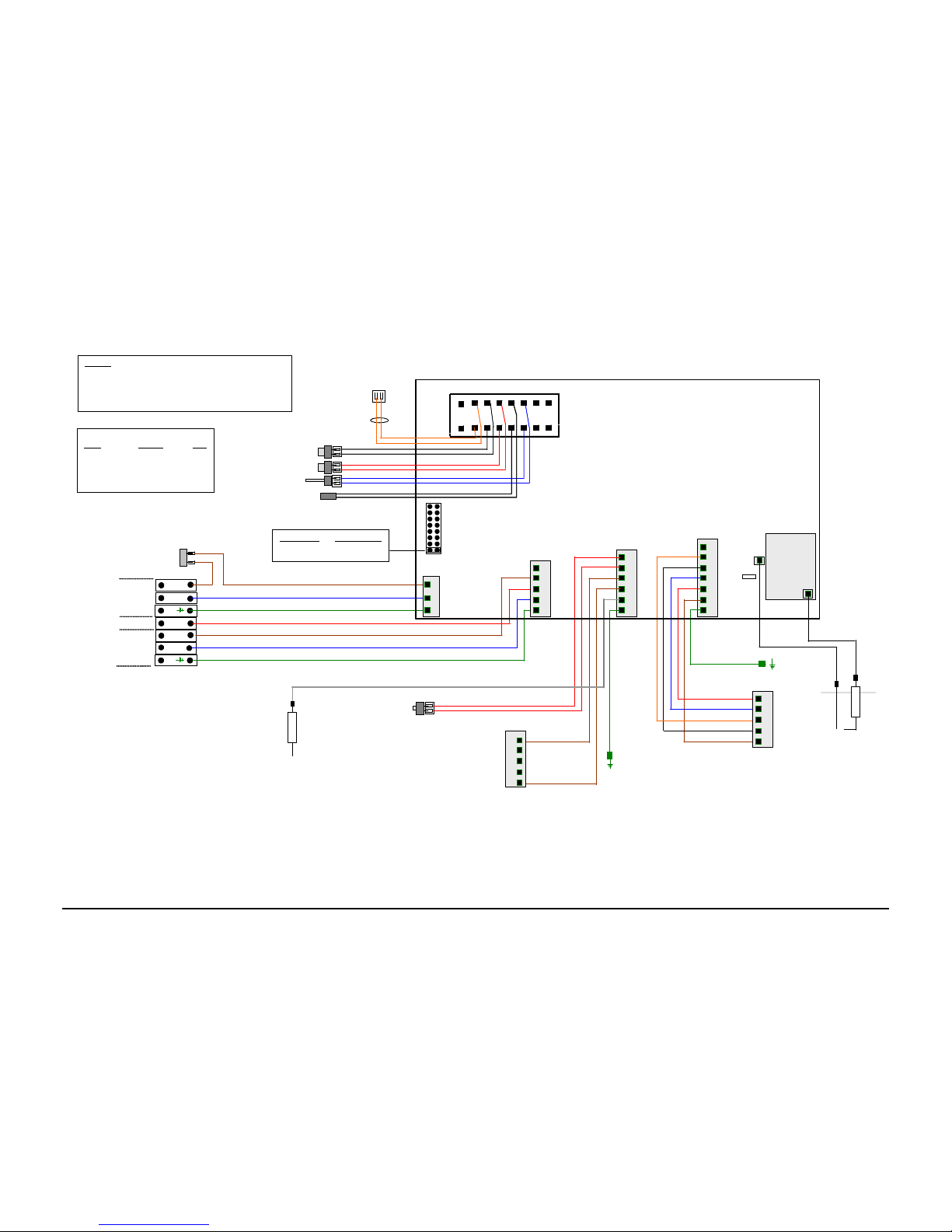
Diagram 8.3 GWS Wall mounted boiler internal wiring diagram (Version: 190105)
Sensors
Boiler Flow – Tasseron -type TSE/12K/±3% DWG No: TSC0B10
Boiler return –Tasseron -type TSE/12K/±3% DWG No: TSC0B10
Flue gas – Tasseron – type TS861/12K/ ±3% DWG No: TSSD2050
OHT - Hawco -Auto-Reset thermal cu-out thermostat
Ref: 03EN-15S040-5x6 95+-4/80 +-4
L
SL_B
E
N
E
L_P
N_P
Boiler switched live - 230V, ac
Mains supply to
boiler, 230V, ac
3
2
1
J2
L (J2-3)
N (J2-2)
E (J2-1)
J7
SL-Boiler (J7-3)
L-Pump (J7-4)
N-Pump (J7-2)
E-Pump (J7-1)
Supply to remote
pump, 230V, ac
J13
Gas valve
earth
Gas valve
connector
Auto reset OHT
OHT_2 (J13-5)
OHT_1 (J13-6)
GV-5 : (J13-4)
GV-1 : (J13-3)
Flame
Sensing
electrode
PTFE insulated high temperature & high tension lead (J13-2)
J9
Fan earth
Fan
connector
F-1 : (J9-2)
F-2 : (J9-5)
F-3 : (J9-6)
F-4 : (J9-4)
F-5 : (J9-3)
(J9-1)
1 2 3 4 5 6 7 8
9 10 11 12 13 14 15 16
J12
J11
Spark
electrode
T2
HT lead
J5
Boiler return sensor
Boiler flow sensor
Control bus
connector
Digimaster Controller
Type B794_3
Flue gas sensor
1
5
4
3
2
1
3
2
1
4
5
6
2
3
4
5
6
7
5
4
3
2
1
5
4
3
2
1
230V, 5A
On-Off switch
ID Resistor
Flying lead
ID Resistor values
Boiler
Resistor T_ID
GB_10 1K 100
GB_15 1K5 86
GB_20 2K2 73
GB_25 3K3 61
GB_30 4K7 51
J3
Jumper 1 – 9 Frost protection
Off (normal) active
On Not active
Diagram 8.3 GWS Wall mounted boiler internal wiring diagram (Version: 190105)
Sensors
Boiler Flow – Tasseron -type TSE/12K/±3% DWG No: TSC0B10
Boiler return –Tasseron -type TSE/12K/±3% DWG No: TSC0B10
Flue gas – Tasseron – type TS861/12K/ ±3% DWG No: TSSD2050
OHT - Hawco -Auto-Reset thermal cu-out thermostat
Ref: 03EN-15S040-5x6 95+-4/80 +-4
L
SL_B
E
N
E
L_P
N_P
Boiler switched live - 230V, ac
Mains supply to
boiler, 230V, ac
3
2
1
J2
L (J2-3)
N (J2-2)
E (J2-1)
J7
SL-Boiler (J7-3)
L-Pump (J7-4)
N-Pump (J7-2)
E-Pump (J7-1)
Supply to remote
pump, 230V, ac
J13
Gas valve
earth
Gas valve
connector
Auto reset OHT
OHT_2 (J13-5)
OHT_1 (J13-6)
GV-5 : (J13-4)
GV-1 : (J13-3)
Flame
Sensing
electrode
PTFE insulated high temperature & high tension lead (J13-2)
J9
Fan earth
Fan
connector
F-1 : (J9-2)
F-2 : (J9-5)
F-3 : (J9-6)
F-4 : (J9-4)
F-5 : (J9-3)
(J9-1)
1 2 3 4 5 6 7 8
9 10 11 12 13 14 15 16
J12
J11
Spark
electrode
T2
HT lead
J5
Boiler return sensor
Boiler flow sensor
Control bus
connector
Digimaster Controller
Type B794_3
Flue gas sensorFlue gas sensor
1
5
4
3
2
1
5
4
3
2
1
3
2
1
4
5
6
2
3
4
5
6
7
5
4
3
2
1
5
4
3
2
1
5
4
3
2
1
230V, 5A
On-Off switch
ID Resistor
Flying lead
ID Resistor values
Boiler
Resistor T_ID
GB_10 1K 100
GB_15 1K5 86
GB_20 2K2 73
GB_25 3K3 61
GB_30 4K7 51
J3
Jumper 1 – 9 Frost protection
Off (normal) active
On Not active
VER: 02.3 _260505 Page:34/41
Page 35
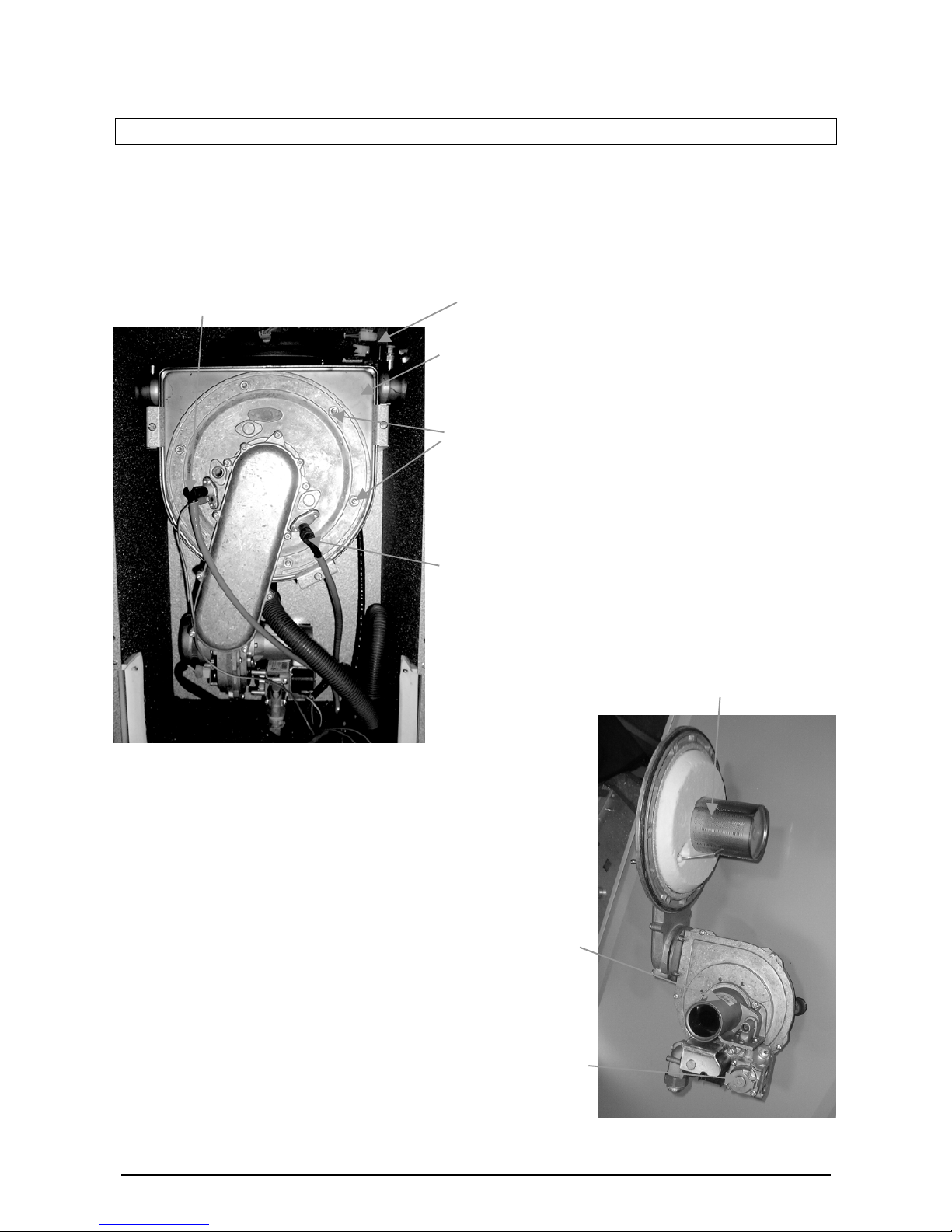
9. REPLACEMENT OF PARTS
9.1. General
A competent person must carry out replacement of parts. Before replacing any parts the boiler must be
isolated from the mains electric supply and the gas must be turned off at the service valve on the boiler.
Unless stated otherwise parts are replaced in the reverse order of removal. After replacing any parts always
test for gas soundness and if necessary carry out a functional test of the controls.
Burner
Gas valve
Temperature
sensors
Combustion chamber
front securing nuts
(6 off)
Flame sensing
electrode
Spark electrode
Heat exchanger
For replacement of parts the front
cover, inner casing panel and
lower casing panel will need to be
removed. The front cover is held
with locating pins at the top and
retaining screws at the bottom.
The retaining screws should be
removed from the bottom and the
panel lifted clear of the locating
pins. To remove the inner casing
undo the four retaining screws
holding the inner casing panel and
the lower casing panel is held by a
further three screws.
9.1.1 The burner, fan, gas valve and venturi form part
of a sub-assembly that must be removed before
one of them can be replaced. To remove the
sub-assembly remove the electrical plugs and
earth connections from the gas valve, fan and
electrodes. Remove the gas connection, then
the six nuts securing the combustion chambe
r
front cover with a 10mm AF spanner. Carefully
withdraw the sub-assembly from the
combustion chamber.
Note: The burner will require a new gaske
t
when refitted.
Venturi
Burner sub assembly
VER: 02.3 _260505 Page:35/41
Page 36

9.2. Spark & Flame sensing Electrodes
For access refer to section General 9.1
Remove the spark plug style connector from the electrode and earth lead in the case of the spark electrode.
Remove the two retaining screws with a Torx T20 driver, carefully withdraw the electrode from the
combustion chamber.
9.3. Ignition & Flame sensing Leads
For access refer to section General 9.1
Pull off the spark plug style connector off the electrode and the spade connector from the control pcb.
9.4. Fan
For access refer to section General 9.1 & 9.1.1
Remove the two slotted screws holding the gas valve and venturi to the fan then remove the four nuts
securing the fan to the gas manifold with a 8mm AF spanner. Check and replace any seals and gaskets
necessary.
9.5. Burner
For access refer to section General 9.1 & 9.1.1. Remove the three screws securing the gas manifold to the
combustion chamber front with a Torx T25 driver. This will release the burner.
The burner size depend upon the model of the boiler (see table below) therefore when replacing the burner
ensure that the correct replacement burner is used.
Gledhill Boiler
model
Burner length
(mm)
Gledhill Part
number
Gas Council number
GB10
GB15 104.6 221.022.001-B
GB20 135.8 221.023.001-B
GB25 167.0 221.024.001-B
GB30 167.0 221.024.001-B
9.6. Temperature Sensors
For access refer to section General 9.1
The flow and return sensors have built in retaining clips and are removed as follows. Remove the
electrical connections from the sensor, the sensor is removed from the pipe by putting equal pressure
on the sensor head and the clip ends that are located 180
o
from each other. The flue gas sensor is
removed with a 15mm AF spanner after having its electrical connections removed.
9.7. Heat exchanger
For access refer to section General 9.1 & 9.1.1
After removing the burner sub-assembly drain the boiler and remove the condense pipe from the
bottom of the heat exchanger. Remove the clips securing the flow and return connections onto the
heat exchanger. Loosen the three heat exchanger securing screws and clamps (two at the top and
one at the bottom) to remove the heat exchanger. CAUTION there will still be some water in the heat
exchanger.
VER: 02.3 _260505 Page:36/41
Page 37

9.8. Insulation
For access refer to section General 9.1 & 9.1.1
Remove the sub assembly as described above and replace the front insulation on the combustion
chamber front cover.
9.9. Overheat thermostat
For access refer to section General 9.1
9.10. Fuses
For access refer to section General 9.1
The fuse is located on the right hand side of the main control pcb.
9.11. On-Off Switch
For access refer to section General 9.1
Remove the electrical connectors from the rear of the switch, squeeze the holding tabs on each end of
the switch. The switch will now push through the front panel.
9.12. Gas Valve
The gas throttle on air/gas venturi (i.e. CO
2
level) and offset pressure settings of the gas valve fitted to
this boiler are factory set and sealed. These settings should not be tempered. The gas valve and
Venturi assembly
must
only be replaced by a factory set and sealed replacement supplied by Gledhill
Ltd.
For access refer to section General 9.1 & 9.1.1
Remove the three screws securi ng the gas valve to the venturi using a Torx T25 drive r. Check and
replace any seals and gaskets necessary. After replacing the gas valve the combustion CO
2
will need
to be checked and adjusted if necessary.
9.13. Controller PCB
For access refer to section General 9.1
Remove the four slot screws securing the Perspex cover and remove the wiring plugs from the pcb.
With a 6mm AF spanner remove the four nylon stand offs securing the control pcb.
VER: 02.3 _260505 Page:37/41
Page 38
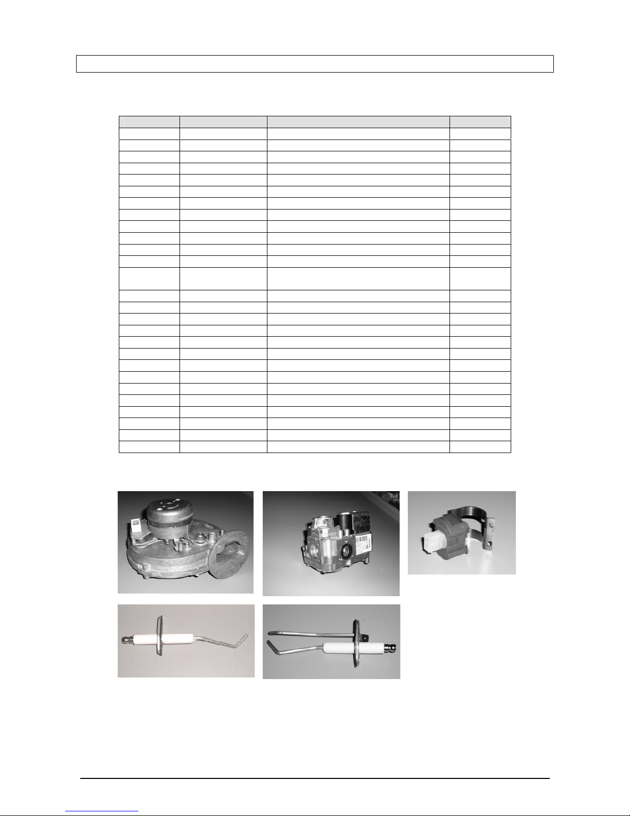
10. SPARE PARTS
10.1.
Key No Part Number Description GC No
5 GM10-35-055 Ignition electrode ******
GM10-25-018 Gasket for electrode ******
4 GM10-35-056 Ionisation electrode ******
GM10-25-004 Gasket for electrode ******
GM xx-xx-xxx Burn er GB-30
GM10-35-047 Burner GB-25, GB-20 ******
GM10-35-044 Burner GB_15 ******
GM xx-xx-xxx Burn er GB-10
GM10-25-074-07 Gasket (for burner) – All models ******
GM10-25-062-02 Boiler door insulation ******
GT339 Air/gas inlet pipe Venturi for GB-30 ******
GT340 Air/gas inlet pipe Venturi for GB-25, GB-
20 and GB-15
GM xx Air/gas inlet pipe Venturi for GB-10
GT451 Ignition lead ******
GT451 Flame sensing lead ******
1 GT335 Fan assembly ******
2 GT185 Gas control valve ******
GT107 Control PCB ******
3 GT333 Temperature sensors (flow & return) ******
GT455 Over heat thermostat ******
GT034 On-Off switch ******
GF199 Terminal guard
2
3
1
4 5
VER: 02.3 _260505 Page:38/41
Page 39

TERMS AND CONDITIONS OF TRADING
1. We only do business upon the Conditions which appear below and no other. Unless we so agree in writing these Conditions shall
apply in full to any supply of goods by us to the exclusion of any Conditions or terms sought to be imposed by any purchaser. These
Conditions of Sale and Warranty Terms override those which are contained on the Invoice Forms and all Sales are now subject to these
Conditions of Sale and Warranty terms only.
2. PRICE
Orders are accepted at the price ruling at the date of receipt of order, this price is our last published list price plus a supplement to allow
for any increase in the price of copper between the dates of publication of our price lists ("the copper price supplement"). An order may
not be cancelled or varied after acceptance without the written consent of the company. Such cancellation or variation shall be subject
to suchreasonable charges as may be appropriate.
3. SPECIFICATION
The goods are supplied in accordance with the Specifi cations (if any) submitted to the Purchaser and any additions and alterations
shall be the subject of an extra charge. Any goods not so specifi ed shall be in accordance with our printed literature or the literature of
any of our component suppliers (subject to any modifications made since publication). If we adopt any changes in construction or design
of the goods, or in the specification printed in our literature, the Purchaser shall accept the goods so
changed in fulfilment of the order.
4. PAYMENT
The invoice price of goods shall be payable within 30 days of despatch by us of our invoice for the goods or such longer time as may be
stated by our quotation or invoice. If we receive payment in full on or before the due date we will allow a discount of 5% except where
we have quoted a special net price. If payment is not received
in full on or before the due date we shall be entitled in addition to the invoice price to:
(i) payment of a sum equal to any increase in the copper price supplement applicable to the particular goods sold between the date of
receipt of order and the date of receipt of payment in full; and
(ii) interest on any part of the invoice price unpaid after the due date at the rate of 3% per annum over the base rate for the time being of
Midland Bank plc.
5. TIME
We give estimates of delivery dates in good faith and time of delivery is not nor shall be made of the essence of any contract nor shall
we be liable for any loss or damage occasioned by delay in delivery.
6. DELIVERY
We deliver free normally by our own vehicles within 25 miles of any of our manufacturing depots. Delivery to any place more than 25
miles from one of our manufacturing depots is subject to our quoted delivery charges.
We reserve the right to make delivery of goods contained in one order by more than one consignment and at different times. Where a
period is agreed for delivery and such period is not extended by our Agreement, the Purchaser shall take delivery within that period. If
the Purchaser fails to take delivery, we shall be entitled at the Purchaser's risk and expense to store the goods at the Purchaser's
premises or elsewhere and to demand payment as if they had been despatched. Off loading at point of delivery shall be the
responsibility of and be undertaken by the Purchaser.
7. SHORTAGES OR DAMAGE
Goods must be inspected before signature of delivery note and any damage, shortage or discrepancy noted on
the delivery note and the goods returned on the same vehicle. The buyer must also give us immediate written
notice of the damage, shortage or discrepancy so that we may prompt investigation.
8. RETURN OF GOODS
Goods may not be returned to the Company except by prior written permission of an authorised officer of the Company and such re turn
shall be subject to payment by the Purchaser of handling and re-stocking charges, transport and all other costs incurred by the
Company.
9. COMPANY LIABILITY
All our goods are made of the best materials from reputable manufacturers and where stated are manufactured to the appropriate
British Standard. Complaints must be given to us immediately, before any action is taken, as responsibility cannot be accepted if repairs
or renewals are attempted on site without our written authority.
Defects caused by corrosion - both internally and externally - of any nature whatsoever, whatever their cause, and defects resulting from
scale deposits are not covered by the guarantee.
Where we agree to rectify any defect, we reserve the right to undertake the work on our own premises.
Provided that our product has been installed in accordance with any instructions for installation any relevant codes of practice and in
accordance with the bye-laws and requirements obtaining in any particular area we give the following warranties:
(1) Domestic and Commercial Open Vented Cylinders and Tanks.
If the copper cylinder or tank or any integral pipework proves to be defective either in materials or workmanship, we will either repair or
supply replacement at our option with the closest substitute in the case of any obsolete product to any address in Great Britain.
(a) free of all charge during the fi rst year after delivery by us.
(b) thereafter at a charge of one-tenth of the then current list price and any copper price supplement and delivery charge during the
second year after delivery by us and increasing by a further one-tenth on the second and subsequent anniversary of delivery by us.
AND FURTHER we will meet the contractors/installers reasonable costs in removing and replacing any defective Open Vented Copper
Cylinder or Tank with defective integral pipework as follows:
(i) in the case of vessels of less than 80 imperial gallons capacity up to a maximum of one-half of the extent of our liability in regard to
the replacement product expressed in (1) (a) and (b) above
ii) in the case of vessels larger than 79 imperial gallons capacity up to a maximum of one-quarter of the extent of our liability in regard to
the replacement product as expressed in paragraphs (1) (a) and (b) above.
(i) in the case of vessels of less than 80 imperial gallons capacity up to a maximum of one-half of the extent of our liability in regard to
the replacement product expressed
in (1) (a) and (b) above
ii) in the case of vessels larger than 79 imperial gallons capacity up to a maximum of one-quarter of the extent of our liability in regard to
the replacement product as expressed in paragraphs (1) (a) and (b) above.
(2) Domestic Mains Fed Products
If the copper storage vessel itself or any integral pipework as part of the storage vessel assembly proves to be defective either in
materials or workmanship, we reserve the right to either repair or supply replacements or the closest possible substitute in the case of
any obsolete product and will collect and deliver to any address in England, Wales and Scotland (excluding all Scottish Islands).
(a) free of all charge during the first year after delivery by us.
(b) thereafter at a charge of one-fifth of the then current list price or any copper price supplement and delivery charge during the second
year after delivery by us increasing by a further one-fifth on the second and subsequent anniversary of delivery by us.
VER: 02.3 _260505 Page:39/41
Page 40

AND FURTHER we will meet the contractors/installers reasonable costs in removing and replacing any defective copper storage vessel
or storage vessel with defective
integral pipework from the Domestic Mains Pressure Range of products up to a maximum of one-third of the extent of our liability in
regard to the replacement product expressed in (2) (a) and (b) above.
(3) Integrated Boiler and Storage Vessel Products and Stand Alone Boilers
In the case of the GulfStream range of products and the Gledhill Boiler range of products, Gledhill guarantees the heat exchanger
(boiler) for material and construction faults for two years and FURTHER we will meet the installer/contractors reasonable costs in
removing and replacing any DEFECTIVE heat exchanger up to a MAXIMUM of one third of the extent of our liability in regard to the
replacement product.
THE RESPONSIBILITY FOR THE EXECUTION OF THIS GUARANTEE LIES WITH THE INSTALLER.
The guarantee becomes null and void if the appliance is used incorrectly, or in the event of proven negligence or incorrectly
implemented repairs OR FAILURE TO CARRY
OUT THE RECOMMENDED INSPECTION/MAINTENANCE. The guarantee also becomes null and void if changes are made to the
appliance without knowledge, or if the serial number on the appliance is removed or made illegible.
The annual service must be carried out by a competent installer in accordance with the advice given by Gledhill and using Gledhill
approved parts.
(4) Components of our products other than Storage Vessels and Integral Pipework. We will either extend to the purchase the same
terms of warranty as we are given by
the manufacturer of the component or if the manufacturer does not give any warranty, replace free of charge any component which
becomes defective within twelve months after the date of the delivery by us and is returned to us at the purchaser’s expense but we
shall not meet the cost of removal or shipping or return of the component or any other cost charges or damages incurred by the
purchaser.
(5) In the case of goods manufactured solely in accordance with our specification and designs and in respect of any installation work
carried out by or on our behalf, our entire liability and the purchaser's sole remedies (subject to (1-4) above) and shall be as follows:
(a) we accept liability for death or personal injury to the extent that it results from our negligence that of our employees agents or
subcontractors.
(b) subject to paragraph (d) below, we accept liability for direct physical damage to tangible property to the extent that such damage is
caused by our negligence that of our employees agents or subcontractors.
(c) our total liability to the purchaser over and above any liability to replace under (1 - 4) above (whether in contract or in tort including
negligence) in respect of any one cause of loss or damage claimed to result from any breach of our obligations hereunder, shall be
limited to actual money damages which shall not exceed £20,000 provided that such monetary limit shall not apply to any liability on the
part of ourselves referred to in paragraph (a) above.
(d) except as provided in paragraph (a) above but otherwise notwithstanding any provision herein contained in no event shall we be
liable for the following loss
or damage howsoever caused and even if foreseeable by us or in our contemplation :(i) economic loss which shall include loss of profi ts, business revenue, goodwill or anticipated savings.
(ii) damages in respect of special indirect or consequential loss or damage (other than death, personal injury and damage to tangible
property).
(iii) any claim made against the purchaser by any other party (save as expressly provided in paragraph (b) above).
(e) except in respect of our liability referred to in paragraph (a) above no claim may be made or action brought (whether in contract or in
tort including negligence) by the purchaser in respect of any goods supplied by us more than one year after the date of the invoice for
the relevant goods.
(f ) nothing in these Conditions shall confer on the purchaser any rights or remedies to which the purchaser would not otherwise be
legally entitled.
(6) Notwithstanding any other provision contained herein the Purchaser's hereby agree to fully indemnify us against any damages
losses costs claims or expenses incurred by us in respect of any claim brought against us by any third party for :(a) any loss injury or damage wholly or partly caused by any goods supplied by us or their use.
(b) any loss injury or damage wholly or partly caused by the defective installation or sub-standard workmanship or materials used in the
installation of any goods supplied by us.
(c) any loss injury or damage in any way connected with the performance of this contract.
PROVIDED that this paragraph (6) will not require the Purchaser to indemnify us against any liability for our own acts of negligence or
those of our employees agents or sub-contractors.
FURTHER in the case of goods supplied by us which are re-sold to and installed by a third party by the Purchaser it will be the sole
responsibility of the Purchaser to test the goods immediately after their installation to ensure that inter alia they are correctly installed
and are in proper working order, and are not likely to cause any loss injury or damage to any person or property.
10. VARIATION OF WARRANTY AND EXCLUSION
Should our warranty and exclusion be unacceptable we are prepared to negotiate for variation in their terms but only on the basis of an
increase in the price to allow for any additional liability or risk which may result from the variation.
Purchasers are advised to insure against any risk or liability which they may incur and which is not covered by our warranty.
11. RISK AND RETENTION OF TITLE
(a) goods supplied by us shall be at the Purchaser's risk immediately upon delivery to the Purchaser or into custody on the Purchaser's
behalf or to the Purchaser's Order. The Purchaser shall effect adequate insurance of the goods against all risks to the full invoice value
of the goods, such insurance to be effective from the time of delivery until property in the goods shall pass to the Purchaser as
hereinafter provided.
(b) property in the goods supplied hereunder will pass to the Purchaser when full payment has been made by the Purchaser to us for :(i) the goods of the subject of this contract.
(ii) all other goods the subject to of any other contract between the Purchaser and us which, at the time of payment of the full price of
the goods sold under this contract, have been delivered to the Purchaser but not paid for in full.
(c) until property in the goods supplied hereunder passes to the Purchaser in accordance with paragraph
(2) above.
(i) the Purchaser shall hold the goods in a fiduciary capacity for us and shall store the same separately from any other goods in the
Purchaser's possession and in a manner which enables them to be identified as our goods.
(ii) the Purchaser shall immediately return the goods to us should our authorised representative so request. All the necessary incidents
associated with a fiduciary relationship shall apply.
(d) the Purchaser's right to possess the goods shall cease forthwith upon the happening of any of the following events, namely :(i) if the Purchaser fails to make payment in full for the goods within the time stipulated in clause 4 hereof.
(ii) if the Purchaser, not being a company, commits any act of bankruptcy, makes a proposal to his or her creditors for a compromise or
does anything which would entitle a petition for a Bankruptcy Order to be presented.
VER: 02.3 _260505 Page:40/41
Page 41

(iii) if the Purchaser, being a company, does anything or fails to do anything which would entitle an administrator or an administrative
receiver or a receiver to take possession of any assets or which would entitle any person to present a petition for winding up or to apply
for an administration order.
(e) the Purchaser hereby grants to us an irrevocable licence to enter at any time any vehicle or premises owned or occupied by the
Purchaser or in the possession of the Purchaser for the purposes of repossessing and recovering any such goods the property in which
has remained in us under paragraph (2) above. We shall not be responsible for and the Purchaser will indemnify us against liability in
respect of damage caused to any vehicle or premises in such repossession and removal being damaged which it was not reasonably
practicable to avoid.
(f ) notwithstanding paragraph (3) hereof and subject to paragraph (7) hereof, the Purchaser shall be permitted to sell the goods to third
parties in the normal course of business. In this respect the Purchaser shall act in the capacity of our commission agent and the
proceeds of such sale :(i) shall be held in trust for us in a manner which enables such proceeds to be identifi ed as such, and :
(ii) shall not be mixed with other monies nor paid into an overdrawn bank account.
We, as principal, shall remunerate the Purchaser as commission agent a commission depending upon the surplus which the Purchaser
can obtain over and above the sum, stipulated in this contract of supply which will satisfy us.
(g) in the event that the Purchaser shall sell any of the goods pursuant to clause (6) hereof, the Purchaser shall forthwith inform us in
writing of such sale and of the identity and address of the third party to whom the goods have been sold.
(h) if, before property in the goods passes to the Purchaser under paragraph (2) above the goods are or become affixed to any land or
building owned by the Purchaser it is hereby agreed and declared that such affixation shall not have the effect of passing property in the
goods to the Purchaser.
Furthermore if, before property in the goods shall pass to the Purchaser under paragraph (2) hereof, the goods are or become affixed to
any land or building (whether or not owned by the Purchaser), the Purchaser shall:(i) ensure that the goods are capable of being removed without material injury to such land or building.
(ii) take all necessary steps to prevent title to the goods from passing to the landlord of such land or building.
(iii) forthwith inform us in writing of such affixation and of the address of the land or building concerned.
The Purchaser warrants to repair and make good any damage caused by the affixation of the goods to or their removal from any land or
building and to indemnify us
against all loss damage or liability we may incur or sustain as a result of affixation or removal.
(i) in the event that, before property in the goods has passed to the Purchaser under paragraph (2) hereof, the goods or any of them are
lost, stolen, damaged or destroyed :(i) the Purchaser shall forthwith inform us in writing ofthe fact and circumstances of such loss, theft, damage or destruction.
(ii) the Purchaser shall assign to us the benefit of any insurance claim in respect of the goods so lost, stolen, damaged or destroyed.
12. NON-PAYMENT
If the Purchaser shall fail to make full payment for the goods supplied hereunder within the time stipulated in clause 4 hereof or be in
default of payment for any other reason then, without prejudice to any of our other rights hereunder, we shall be entitled to stop all
deliveries of goods and materials to the Purchaser, including deliveries or further deliveries of goods under this contract. In addition we
shall be entitled to terminate all outstanding orders.
13. RISK
All goods sold by us shall be at the sole risk of the Purchaser from the date of despatch by us of the invoice for their price.
14. VALUE ADDED TAX
All prices quoted are exclusive of Value Added Tax which will be charged at the rate ruling at the date of dispatch of invoice.
15. TRADE SALES ONLY
We are only prepared to deal with those who are not consumers within the terms of the Unfair Contract Terms Act 1977, the Sale of
Goods Act 1979 and the Supply of
Goods and Services Act 1982. Accordingly any person who purchases from us shall be deemed to have represented that he is not a
consumer by so purchasing.
16. JURISDICTION
The agreement is subject to English/Scottish law and any dispute arising hereunder shall be settled in accordance therewith dependent
upon the location.
VER: 02.3 _260505 Page:41/41
 Loading...