

Page 1
Installation and Servicing Instructions
CS1
Wall mounted condensing boiler for central heating
ZB 7-28 CS1
6 720 610 577-00.10
GC-Number: 41 108 02
6 720 610 601 GB (03.02) OSW
Page 2

2
Contents
Contents
31
Safety precautions 3
Symbols 3
1 Details of the appliance 4
1.1 EC Declaration of Conformity 4
1.2 Standard package 4
1.3 Description of appliance 4
1.4 Accessories 5
1.5 Casing dimensions 5
1.6 Layout of appliance 6
1.7 Function (with optional extra motorised valve) 7
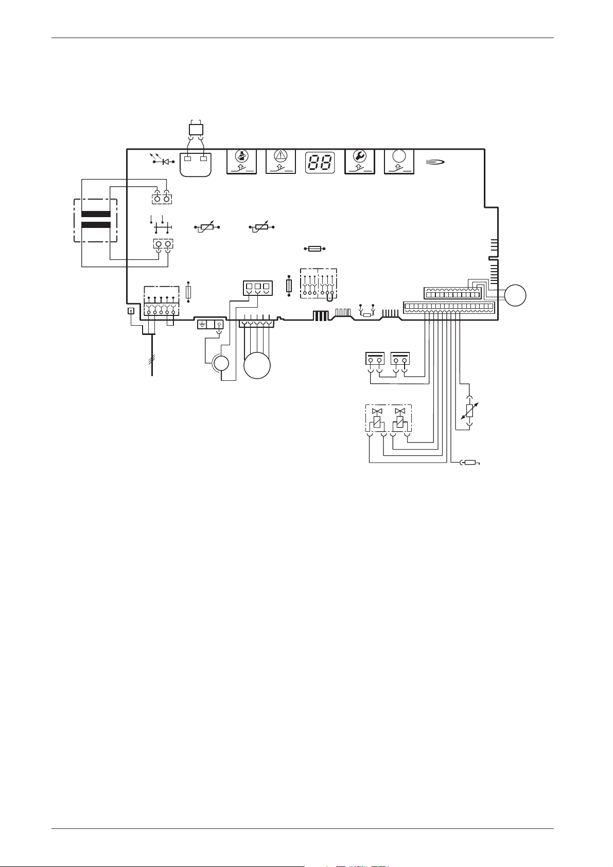
1.8 Electrical wiring diagram 8
1.9 Technical data 9
2 Installation regulations 10
3 Installation 11
3.1 Important remarks 11
3.2 Sealed systems 11
3.3 Siting the appliance 13
3.4 Wall mounting frame assembly 14
3.5 Pre-piping the system 14
3.6 Fitting the appliance 15
3.7 Checking the connections 16
3.8 Flue Systems 16
3.8.1 Siting the Flue Terminal 17
3.8.2 Installation of the flue 18
3.8.3 Flue duct preparation and assembly 20
4 Electrical connections 21
4.1 Connecting the appliance 21
4.2 Mains Voltage external controls connections 22
4.3 Wiring to your system 22
4.3.1 Pre-wired Remote S Plan 22
5 Commissioning 23
5.1 Commissioning 23
5.2 Switching the appliance on/off 24
5.3 Switching on the central heating 24
5.4 System controls 24
5.5 Appliances with optional plug-in
diverter valve: Setting hot water temperature 25
5.6 Frost protection 25
5.7 Pump anti-seize function 25
5.8 Fault Condition 25
6 Individual settings 26
6.1 Mechanical settings 26
6.1.1 Checking the size of the expansion vessel 26
6.1.2 Setting the central heating flow temperature 26
6.1.3 Changing the heating pump characteristic 26
6.2 Settings on the Bosch Heatronic 27
6.2.1 Operating the Bosch Heatronic 27
6.2.2 Selecting the pump control mode for central
heating mode (Service Function 2.2) 27
6.2.3 Setting the anti-cycle time
(Service Function 2.4) 27
6.2.4 Setting the maxim CH flow temperature
(Service Function 2.5) 28
6.2.5 Setting the switching difference
(Service Function 2.6) 28
6.2.6 Setting the heating output
(Service Function 5.0) 28
6.3 Setting the gas/air ratio 28
7 Converting the appliance to
different gas types 29
7.1 Setting the gas/air ratio 29
7.2 Testing combustion air/flue gas at set
heat output 31
7.2.1 Testing the O
or CO
2
level in the
2
combustion air 31
7.2.2 Testing CO and CO
2
8 Maintenance 32
8.1 Pre-Service Check List 33
8.2 Description of servicing operations 34
8.3 Replacement of Parts 37
8.3.1 PCB control board and transformer 37
8.3.2 Fan Assembly 38
8.3.3 Pump 38
8.3.4 3-way diverter valve 38
8.3.5 3-way diverter valve motor 39
8.3.6 Sensors 39
8.3.7 Gas Valve 39
8.3.8 Electrode assembly 39
8.3.9 Pressure gauge 40
8.3.10Expansion vessel 40
8.3.11Pressure Relief Valve 40
8.3.12Burner 40
8.3.13Primary Heat Exchanger 40
9 Appendix 41
9.1 Fault Codes 41
9.2 Short parts list 42
9.3 Heating/hot water output settings (N.G) 42
9.4 Heating/hot water output settings (L.P.G) 42
9.5 Operational Flow diagrams 43
9.5.1 Central heating function 43
6 720 610 601 GB (03.02)
Page 3

B
B
B
B
B
B
B
B
B
B
B
B
B
B
B
B
B
B
B
B
B
Safety precautions
Safety precautions
If you smell gas
Turn off gas service cock at the meter.
Open windows and doors.
Do not operate any electrical switches.
Extinguish any naked flames.
Telephone your gas company.
If you smell fumes from the appliance
Switch off appliance (see page 24).
Open windows and doors.
Fitting and modifications
Fitting of the appliance or any controls to the appliance may only be carried out by a competent engineer in accordance with the Gas Safety (Installation
and Use) Regulations 1998.
Flue systems must not be modified in any ways other
than as described in the fitting instructions.
This appliance is for use on sealed primary systems only.
Maintenance
The user is recommended: to have the system
regularly serviced in order to ensure that it functions
reliably and safely.
Use only original spare parts!
Symbols
Safety instructions in this document
are identified by a warning-triangle symbol and are printed on a grey background.
Notes containing important information
are identified by the symbol shown on the
i
left. They are bordered by horizontal lines
above and below the text.
Combustible materials
Do not store or use any combustible materials
(paper, thinners, paints etc.) in the vicinity of the
appliance.
Health and safety
This appliance contains no asbestos products.
There is no potential hazard due to the appliance
being electrically unsafe.
There are no substances used in the construction
that are a potential hazard in relation to the COSHH
Regulations (Control of Substances Hazardous to
Health Regulations 1988).
Combustion air/Ambient atmosphere
The combustion air/ambient atmosphere should be
kept free of chemically aggressive substances (e.g.
halogenated hydrocarbons which contain chlorine or
fluorine compounds). This will prevent corrosion.
Instructions to the customer
Explain to the customer how the appliance works
and how to operate it.
Advise the user that he/she must not make any modifications to the appliance or carry out any repairs on it.
These instructions are to be left with the user or at
the Gas meter.
Important: These instructions apply in the UK only.
6 720 610 601 GB (03.02)
3
Page 4
Details of the appliance
4
1 Details of the appliance
1.1 EC Declaration of Conformity
This appliance is in accordance with the applicable
requirements of the Gas Appliance Directive, Boiler
Efficiency Directive, Electromagnetic Compatibility
Directive and the Low Voltage Directive.
PIN
Category
UK
Appliance Type
Table 1
1.2 Standard package
• Gas condensing boiler for central heating
• Wall mounting frame
• Clamp for securing flue duct kit
• Fixings (screws etc.)
• Set of documentation for appliance
• Pre-plumbing manifold
• Condensate drain pipe.
CE-0085 BL 0507
II
2H 3P
C
, C
13
33
1.3 Description of appliance
• Wall-mounted appliance, siting not dependent on
room size
• Natural gas models are low-emission appliances
• Multifunction display
• Bosch Heatronic control system
• Automatic ignition
• Modulating control
• Full safety systems incorporating Bosch Heatronic
with flame ionisation monitoring, solenoid valves and
temperature sensors
• Concentric flue/air duct with testing point for
CO
/CO
2
• Regulated speed fan
• Pre-mix burner
• Temperature control for central heating
• Safety temperature limiter in 24 V electrical circuit
• Three-speed central heating pump with automatic
vent
• Relief valve, pressure gauge, expansion vessel
• Flue gas temperature limiter (105 °C)
• Condensate Trap
• Connecting possibility for S-Plan System.
6 720 610 601 GB (03.02)
Page 5
1.4 Accessories
• Standard horizontal flue kit at 100 mm outside
diameter for flues upto 4 m in length.
• Flue duct kits for horizontal (125 mm outside
diameter) for flue lengths upto 13 m and vertical flue
systems for flue lengths upto 15 m. Fitting instructions are sent with these kits.
• Heating programmers
• Timer
• Security kit
• Motorised valve is available as an optional extra. If
this option is used then the DT2, TR2 Optimising
Room Thermostat and the Night Set Back Module
will be required.
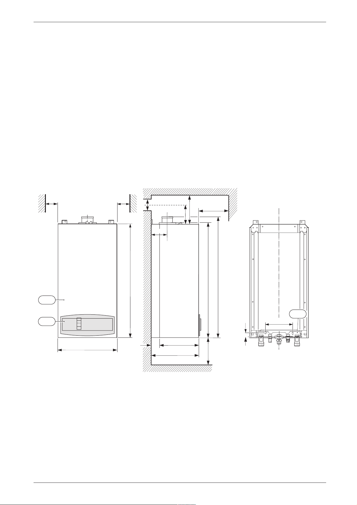
1.5 Casing dimensions
13
X
Y
Z
Details of the appliance
min.
101
103
min.
*
5
5
Z
*
X
Y
600
*
120
850
861
906
13
200
30
440
35
360
395
*
200
6 720 610 601- 01.3O
Fig. 1
Manifold assembly
101 Outer case
103 Facia cover
Standard Concentric Horizontal Flue System: min. 310 mm
Alternative Concentric Flue System: min. 250 mm
Standard Concentric Horizontal Flue System: 158 mm
Alternative Concentric Flue System: 121 mm
Standard Concentric Horizontal Flue System: 105 mm
Alternative Concentric Flue System: 130 mm
*
For servicing the appliance
6 720 610 601 GB (03.02)
5
Page 6
Details of the appliance
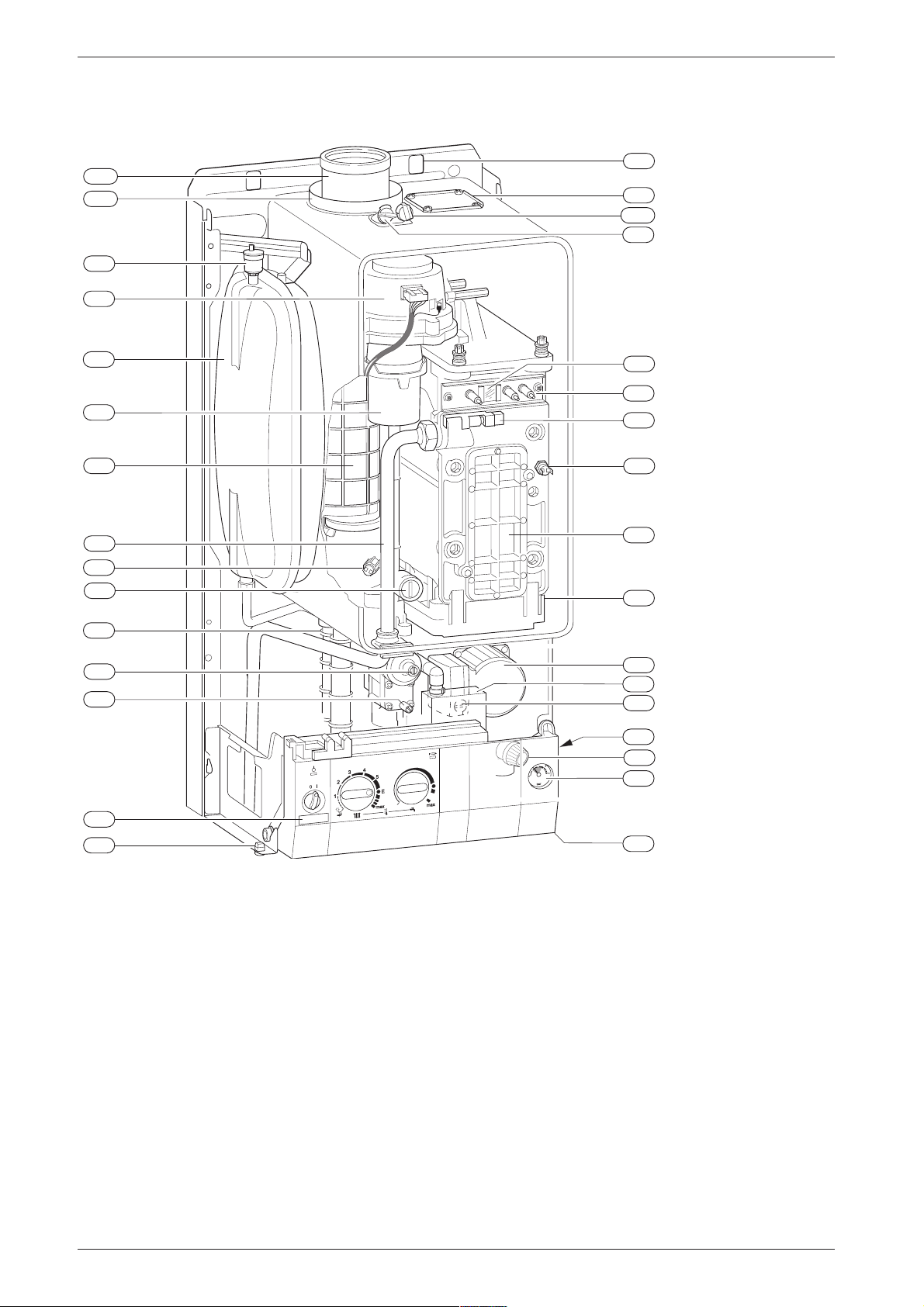
1.6 Layout of appliance
6
4
6
7
9
15
18
20
27
29
36
43
63
64
221.1
221.2
27
226
20
29
271
43
9
63
120
349
234.1
234
102
32.1
36
6
415
416
358
64
7
295
417
Fig. 2
Heatronic control
Heat exchanger safety temperature limiter
Testing point for gas supply pressure
8.1 Pressure gauge
Flue gas temperature limiter
Relief valve
Pump
18.1 Pump speed selector switch
Expansion vessel
Automatic air vent
Air gas Mixer unit
32.1 Electrode assembly
Temperature sensor in CH flow
CH flow
Adjustable gas flow restrictor
Adjusting screw for min. gas flow volume
102 Inspection window
120 Fixing points
221.1 Flue duct
18
423
18.1
418
15
8.1
4
6 720 610 596-01.2O
221.2 Combustion air intake
226 Fan assembly
295 Appliance type sticker
234 Testing point for combustion products
234.1 Testing point for combustion air
271 Flue duct
349 Cover plate for twin flue duct connection
358 Condensate trap
415 Cover plate for cleaning access
416 Condensate collector
417 Clip for fixing outer case
418 Data plate
423 Siphon
6 720 610 601 GB (03.02)
Page 7
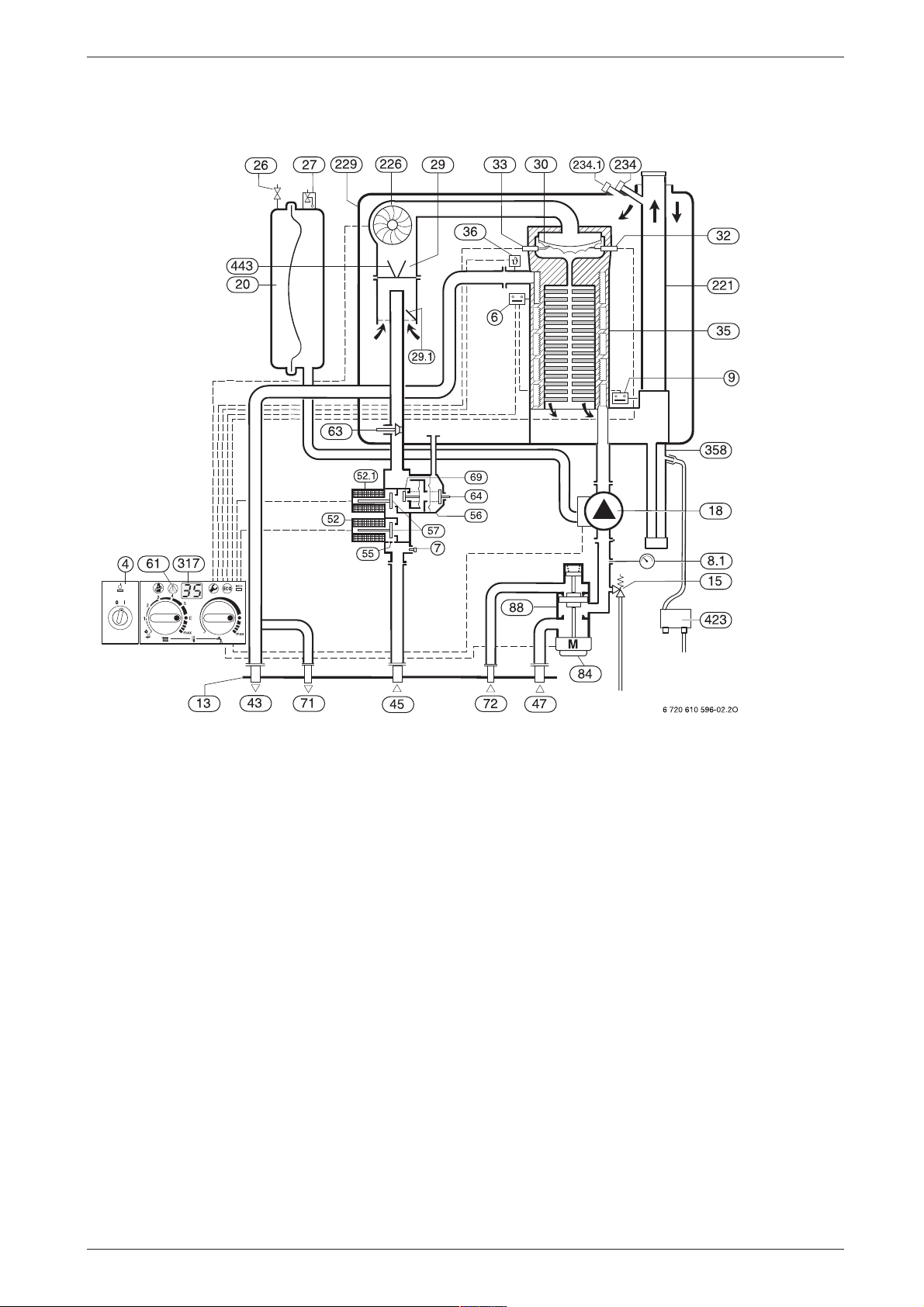
1.7 Function (with optional extra motorised valve)
Details of the appliance
4
6
7
9
13
15
18
Fig. 3
Bosch Heatronic control
Temperature limiter, heat exchanger
Testing point for gas supply pressure
8.1 Pressure gauge
Flue gas temperature limiter
Manifold
Safety valve
Central heating pump
20 Expansion vessel
26 Charging valve
27 Automatic vent
29 Mixer unit
29.1 Bi-metallic thermostat for combustion air compensation
30 Burner
32 Flame sensing electrode
33 Igniter electrode
35 Heat exchanger with cooled combustion chamber
36 Temperature sensor in CH flow
43 CH flow
45 Gas inlet
47 CH return
52 Solenoid valve 1
52.1 Solenoid valve 2
55 Filter
56 Gas valve CE 427
57 Main valve disc
61 Reset button
63 Adjustable gas flow restrictor
64 Adjusting screw for min. gas inlet flow volume
69 Control valve
71 Storage water heater outflow (only with motorised valve)
72 Storage water heater return (only with motorised valve)
84 Motor (optional extra)
88 3-way valve (optional extra)
221 Flue duct
226 Fan
229 Inner casing
234 Testing point for flue gas
234.1 Testing point for combustion air
317 Display
358 Condensate trap
423 Siphon
443 Diaphragm
6 720 610 601 GB (03.02)
7
Page 8
Details of the appliance
1.8 Electrical wiring diagram
33
364
4.1
365
61
317
o - orange bl - black r - red
366
367
ECO
363
25 V
153
230V/AC
135
302
230 V
328
L
Ns
NLs
136
151
LR
328.1
M
mains supply
18
Fig. 4
4.1 Ignition transformer
6 Temperature limiter, heat exchanger
9 Flue gas temperature limiter
18 Pump
32 Flame sensing electrode
33 Ignition electrode
36 Temperature sensor in CH flow
52 Solenoid valve 1
52.1 Solenoid valve 2
56 Gas valve CE 427
61 Reset button
84 Motor (optional extra)
135 Master switch
136 Temperature control for CH flow
151 Fuse, slow 2.5 A, AC 230 V
153 Transformer
161 Link
226 Fan
300 Code plug
302 Earth connection
310 Temperature control for hot water
312 Fuse, slow T 1,6 A
313 Fuse, slow T 0,5 A
314 Connector for programmer TA212E
315 Terminal block for programmer
317 Digital display
318 Connector for timer
328 Terminal block for AC 230 V Mains supply
310
M
226
313
312
315
89
1247
300
52
314
6
9
r
r
52.1
161
56
bl
bl
bl
bl
328.1 Link
363 Indicator lamp for burner
364 Indicator lamp for power supply
365 “Chimney sweep” button
366 Service button
367 ECO button
318
o
o
36
32
6 720 610 601-02.2O
84
p
p
M
p
8
6 720 610 601 GB (03.02)
Page 9
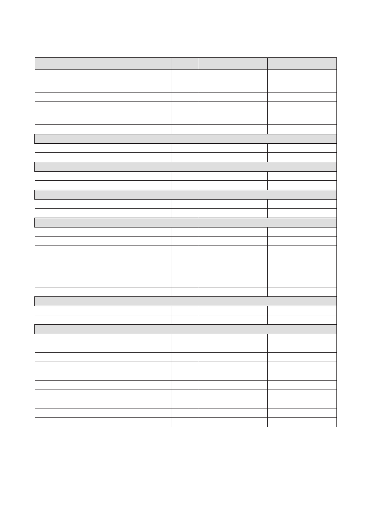
1.9 Technical data
Details of the appliance
Units Natural gas Propane
Max. rated heat output net 40/30˚C central heating
Max. rated heat output net 50/30˚C central heating
Max. rated heat output net 80/60˚C central heating
kW
kW
kW
29.3
29.0
27.4
29.3
29.0
27.4
Max. rated heat input net kW 27.7 27.7
Min. rated heat output net 40/30˚C
Min. rated heat output net 50/30˚C
Min. rated heat output net 80/60˚C
kW
kW
kW
8.4
8.3
7.4
11.6
11.4
10.5
Min. rated heat input net kW 7.6 10.8
Maximum gas flow rate – After 10 minutes from lighting
Natural gas G20 (CVnet 34.02 MJ/m
3
LPG (CVnet 88 MJ/m
) kg/h - 2.1
3
)m
3
/h 2.9 -
Gas supply pressure
3
Natural gas G20 (CVnet 34.02 MJ/m
3
LPG (CVnet 88 MJ/m
) mbar - 37
) mbar 20 -
Expansion vessel
Charge pressure bar 0.75 0.75
Total capacity l 10 10
Flue
Flue gas temp. 80/60˚C, rated/min. load ˚C 67/55 67/55
Flue gas temp. 40/30˚C, rated/min. load ˚C 43/32 43/32
Residual delivery pressure
(inc. pressure drop in air intake duct) Pa 80 80
level at max. rated heat output
CO
2
CO
level at min. rated heat output
2
-class 5 5
NO
x
%
%
9.2
8.8
10.8
10.5
SEDBUK figure, Band A % 90.7 90.7
Condensate
Max. condensation rate (t
= 30˚C) l/h 2.3 2.3
R
pH-value, approx. 4.8 4.8
General Data
Electrical power supply voltage AC ... V 230 230
Frequency Hz 50 50
Max. power consumption W 101 101
Noise output level dB(A) 36 36
Appliance protection rating IP X4D X4D
Max. CH flow temperature ˚C nom. 90 nom. 90
Max. permissible operating pressure (CH) bar 2.5 2.5
Permissible ambient temperatures ˚C 0 - 50 0 - 50
Nominal capacity of appliance l 3.75 3.75
Weight (excluding packing) kg 46 46
Table 2
6 720 610 601 GB (03.02)
9
Page 10
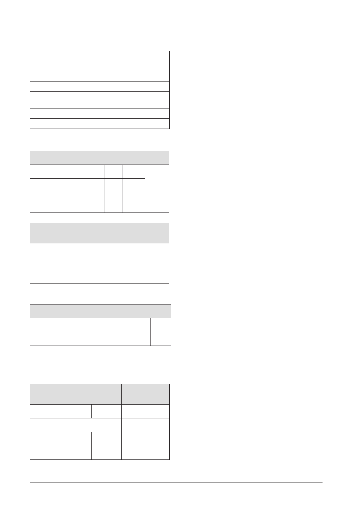
Installation regulations
Condensate analysis, mg/l
Ammonium 1.2 Nickel 0.15
Lead ≤ 0.01 Mercury ≤ 0.0001
Cadmium ≤ 0.001 Sulphate 1
Chromium ≤ 0.005 Zinc ≤ 0.015
Halogenated
hydrocarbons ≤ 0.002
Hydrocarbons 0.015 Vanadium ≤ 0.001
Copper 0.028 pH-value 4.8
Tin ≤ 0.01
Table 3
Flue system
HORIZONTAL 100 mm – Standard
Overall Diameter of Duct mm 100
Flue Terminal / Duct
Assembly Length
Extension Duct Length mm 1000
mm 600
Max.
4 m
Table 4
ALTERNATIVE HORIZONTAL 125 mm FLUE
SYSTEM
Overall Diameter of Duct mm 125 Max.
13 m
(inclu-
Flue Terminal / Duct Assembly mm 1030
ding
turret)
Table 5
VERTICAL 125 mm FLUE SYSTEM
Overall Diameter of Duct mm 125 Max.
15 m
Flue Terminal / Duct Assembly mm 1360
2 Installation regulations
Gas Safety (Installation & Use) Regulations 1998: All
gas appliances must be installed by a competent person. Failure to install correctly could lead to prosecution.
The manufacturers notes must not be taken, in any way,
as overriding statutory obligations.
The appliance must be installed in accordance with the
current IEE Wiring Regulations, local Building Regulations, Building Standards (Scotland) (Consolidation),
bye-laws of the local Water Company, Health and
Safety Document 635 (Electricity at Work Regulations
1989) and any other local requirements.
Product Liability regulations indicate that, in certain circumstances, the installer can be held responsible, not
only for mistakes on his part but also for damage resulting from the use of faulty materials. We advise the
installer to avoid any risk by using only quality approved
branded fittings.
The relevant British Standards should be followed i.e.
• BS 6798: Specification for the installation of gas
fired hot water boilers of rated input not exceeding
60kW
• BS 5449: Central Heating for Domestic Premises
• BS 5546: Installation of gas hot water supplies for
domestic purposes
• BS 5440:1: Flues and ventilation for gas appliances
of rated input not exceeding 70 kW (net): Flues
• BS 5440:2: Flues and ventilation for gas appliances
of rated input not exceeding 70 kW (net): Air
Supply
• BS 6891: Installation of low pressure gas pipework
installations up to 28 mm (R1).
• BS 7074:1: Code of practice for domestic heating
and hot water supply
• BS 7671: Requirements for Electrical Installation.
These instructions must be followed.
Table 6
Elbow - 90 ° Equivalent length 2 m
Bend - 45 ° Equivalent length 1m
Gas supply
Total length of gas supply pipe
(metres)
369
3
Gas discharge rate (m
8.7 5.8 4.6 22
18.0 12.0 9.4 28
/h)
Table 7
10
Pipe diameter
(mm)
6 720 610 601 GB (03.02)
Page 11
Installation
3 Installation
B Always turn off the gas cock before car-
rying out any work on components
which carry gas.
Fixing of the appliance, gas and flue connections, commissioning of the system
i
and electrical connections may only be
carried out by competent persons authorised by CORGI.
3.1 Important remarks
B Appliance should only be installed in sealed central
heating systems.
B To avoid gas formation in the system, galvanised
radiators or pipes must not be used.
B If a room thermostat is used: do not fit a thermostatic
radiator valve on the radiator in the primary room.
B Add a suitable anti-freeze fluid compatible with alu-
minium to the water in the central heating system.
Suitable products are available from Betz-Dearborn
Tel.: 0151 4209563 and Fernox Tel.: 01799
550811.
B In our experience, the addition of sealing agents to
the water in the central heating system can cause
problems (deposits in the heat exchanger). For that
reason we advise against their use.
3.2 Sealed systems
The appliance must not be operated without the system
being full of water, properly vented and pressurised.
The expansion vessel has a volume of 10 litres and is
charged to a pressure of 0.75 bar.
The water capacity of the system is shown in table 10,
page 26. If a greater capacity is required then an additional expansion vessel must be fitted into the system
return as close to the appliance as possible. The system
pressure can be set up to a maximum of 1.5 bar with 1
bar being the normal setting.
If the system pressure is greater than 2.5 bar when the
appliance is operating at maximum temperature then an
additional expansion vessel must be fitted into the system return as close to the appliance as possible.
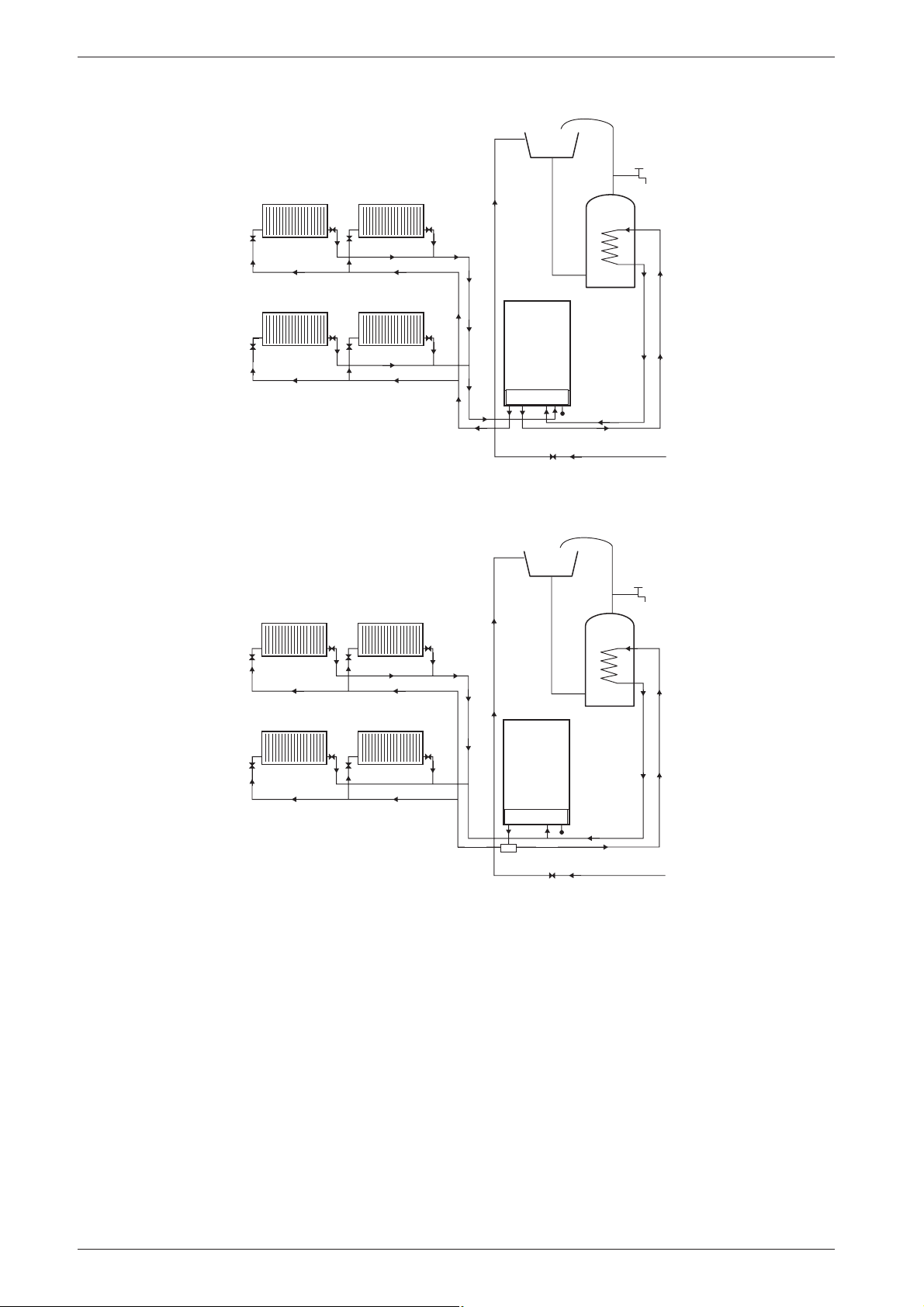
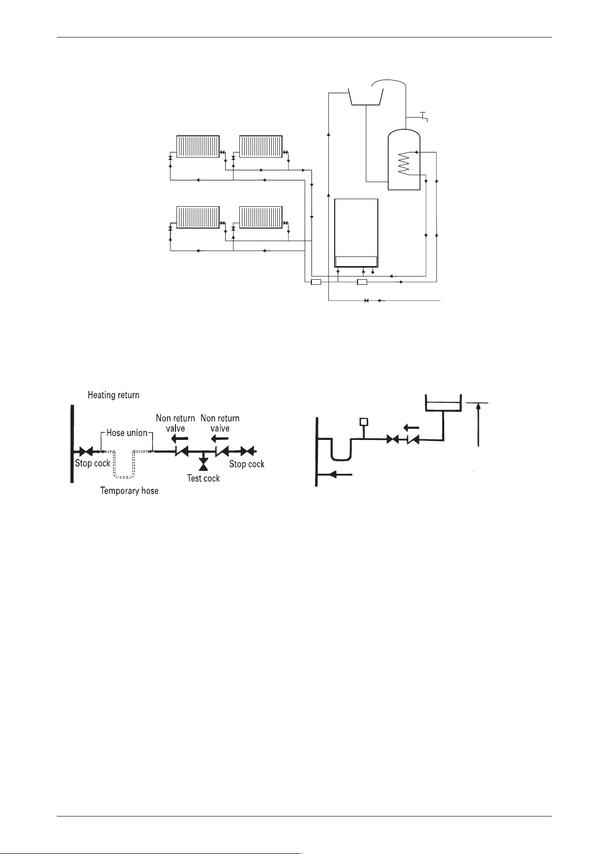
The filling point must be at low level and arranged as
shown in figs. 5 and 8.
The pressure relief valve is set to operate at 3 bar.
There must be no connection to the mains without the
approval of the local water company. All connections in
the system must be capable of withstanding a pressure
of up to 3 bar and the radiator valves conform to the
requirements of BS 2767:10.
If Thermostatic Radiator Valves are fitted then it is recommended that primary radiator is left open.
Repeated venting probably indicates a leak and this
must be rectified to ensure the proper operation of the
appliance.
No galvanised radiators or pipes must be used.
If any system water treatment is required then
only products suitable for use with Aluminium
shall be used i.e Fernox- Copal or Superconcentrate or Sentinal X100, in accordance with the
manufacturers instructions. The use of any other
substances will invalidate the guarantee. The pH
value of the system water must be less than 8 or
the appliance guarantee will be invalidated.
A drain cock to BS2879 must be fitted to the lowest
point of the system.
IMPORTANT: Check that no dirt is left in the
water pipework as this could damage the appliance. Thoroughly flush the heating system and
the mains water supply before fitting the appliance to the wall in accordance with the recommendations of BS7593:1992.
6 720 610 601 GB (03.02)
11
Page 12
Installation
Note:
A drain cock
should be fitted
at the lowest
RV
LV LV
RV
point of the
heating circuit
and beneath
the appliance
RV
Radiator Valve - Flow RV
Lockshield Valve - Return LV
LV LV
RV
Fig. 5 System layout if using built-in diverter valve
Note:
A drain cock
should be fitted
at the lowest
point of the
heating circuit
and beneath
the appliance
RV
RV
LV LV
RV
LV LV
RV
APPLIANCE
Refer to
Appliance
Diagram
Heating Return
Heating Flow
Stop Valve Fixed Cylinder Type
APPLIANCE
Refer to
Appliance
Water
Flow
Diagram
Water
Flow
CYLINDER
Safety Discharge
Hot Water Flow
BS
INDIRECT
CYLINDER
INDIRECT
Cylinder Return
6 720 610 601-04.1O
Mains Cold Water
Cylinder Return
Radiator Valve - Flow RV
Lockshield Valve - Return LV
Fig. 6 System layout if using external diverter valve
12
Heating Return
Heating Flow
Diverter
Valve
Stop Valve Fixed Cylinder Type
Safety Discharge
BS
Hot Water Flow
Mains Cold Water
6 720 610 601-05.1O
6 720 610 601 GB (03.02)
Page 13
Installation
Note:
A drain cock
should be fitted
at the lowest
RV
LV LV
RV
point of the
heating circuit
and beneath
the appliance
RV
Radiator Valve - Flow RV
Lockshield Valve - Return LV
LV LV
RV
Fig. 7 System layout if using twin zone valves (S) plan
Sealed system filling and make up
Heating return
Non return
valve
Non return
valve
Heating return
Hose union
APPLIANCE
Refer to
Appliance
Water
Flow
Diagram
Heating Return
Heating Flow
CH
Zone
Val ve
Stop Valve Fixed Cylinder Type
Safety Discharge
DHW Zone Valve
BS
Auto
air vent
Non return
valve
INDIRECT
CYLINDER
Mains Cold Water
Cylinder Return
Hot Water Flow
6 720 610 601-06.1O
Make up
vessel
Stop cock
Test cock
Temporary hose
Fig. 8
3.3 Siting the appliance
Regulations concerning the Installation Site
B Relevant national regulations must be complied with
section 3.8.1.
B Consult the installation instructions for details of min-
imum clearances required.
Combustion air
In order to prevent corrosion, the combustion air must
not contain any corrosive substances.
Substances classed as corrosion-promoting include
halogenated hydrocarbons which contain chlorine and
fluorine compounds and are contained in some solvents, paints, adhesives, aerosol propellants and
household cleaners, for example.
Stop
cock
Fill point
1000mm (39 in)
above the highest
point of the system.
6 720 611 137 - 29.1O
Surface temperature
The max. surface temperature of the casing and the flue
is less than 85 °C.
This means that, no special safety precautions are
required with regard to flammable building materials
and fitted furniture. The specified clearences must be
maintained.
Cupboard/Compartment
The appliance can be installed in a cupboard/compartment need for airing clothes providing that the requirements of BS 6798 and BS 5440:2 are followed. The
low casing losses from the appliance eliminate the need
for ventilation openings in the compartment.
6 720 610 601 GB (03.02)
13
Page 14
Installation
3.4 Wall mounting frame assembly
B Take the wall mounting frame out of the package and
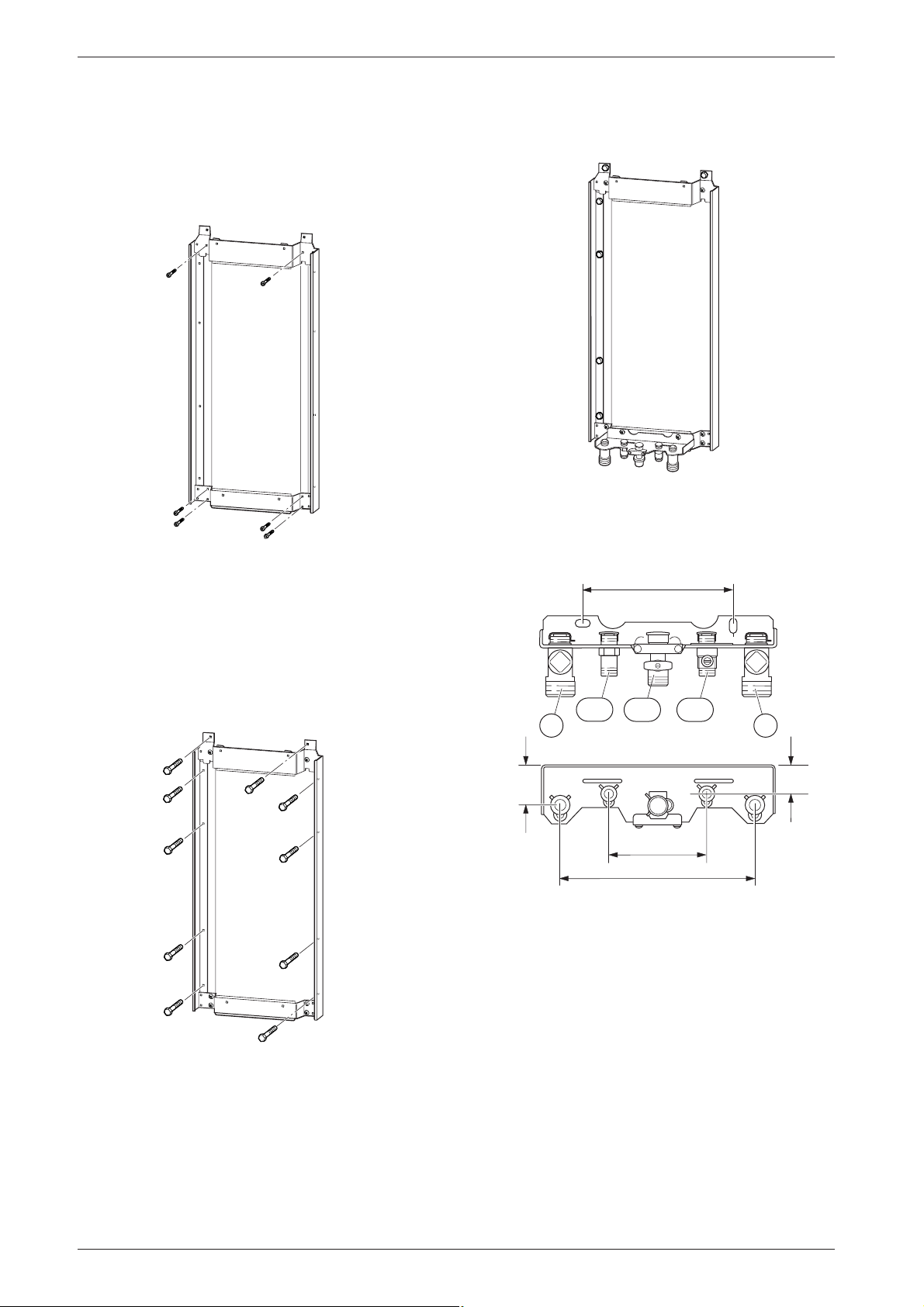
screw together with 6 screws as shown in fig. 9. Use
the inner lugs on the top and bottom horizontal sections for the appliances that are 440 mm wide.
6 720 610 576-04.1O
Fig. 9
B Hold the wall-mounting frame against the wall ensur-
ing that it is vertical.
B Mark the position of the flue duct hole if a rear flue is
to be used. Refer to fig. 1 and 18.
B Mark the holes for the wall mounting frame onto the
wall, drill and plug the holes and screw the wall
mounting frame to the wall with the screws provided.
B Screw the pre-plumbing manifold with two screws to
the wall mounting frame.
6 720 610 576-11.1O
Fig. 11
3.5 Pre-piping the system
200
171
172112
4743
Fig. 10
6 720 610 576-05.1O
50
35
120-130
260
6 720 610 576-06.1O
Fig. 12 Manifold
43 CH flow
47 CH return
112 Gas cock
171 Optional cylinder flow (used only with motorised valve)
172 Optional cylinder return (used only with motorised valve)
B A drain tap should be fitted at the lowest point of the
central heating system.
B WRAS approved filling loop must be fitted.
14
6 720 610 601 GB (03.02)
Page 15
Installation
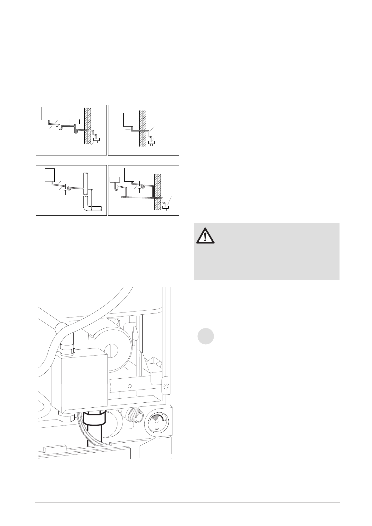
Condensate Termination and Route
The condensate connection on the British Gas/Bosch
appliances is in 22 mm plastic. The pipe should be
extended and run away from the appliance with a constant fall of 2.5 ° or 40 mm in every metre.
The condensate pipe can terminate into any of four
areas:
Boiler
Ø 22 min.
Siphon
No length
restriction
The gradient of the discharge pipe
should be 2.5° (40 mm/m) minimum
An internal waste system
Boiler
No length
restriction
The gradient of the discharge pipe
should be 2.5° (40 mm/m) minimum
The rainwater system
Sink
75 min. trap
Ø 22 min.
75 min. trap
Invert
Open end of pipe direct
into gully, below ground
but above water level
Internal soil
and vent stack
450 min.
Boiler
External length of
Siphon
Ø 22 min.
Use waterproof pipe work
insulation in very exposed
positions
The gradient of the discharge pipe should be
2.5° (40 mm/m) minimum
An external waste system
Boiler
Sink
Siphon
Ø 22 min.
The gradient of the discharge pipe
should be 2.5° (40 mm/m) minimum
An external purpose made soakaway
pipe 2m min.
Open end of pipe
direct into gully,
below ground but
above water level.
No length
restriction
Open end of pipe
75 min. trap
direct into gully,
below ground but
above water level
6 720 610 596 -03.1O
Fig. 13
Whilst all of the above methods are acceptable it is
always the best practice to terminate the condense
pipe via an internal waste system.This will eliminate the
need for any external condensate pipe runs which can
be susceptible to freezing in extreme weather.
External condensate pipework
All British Gas/Bosch condensing boilers have within a
syphonic condensate trap. Rather than the condensate
constantly dripping into the discharge pipe, the condensate is collected into a trap which releases it in
100 ml quantities.
This will help prevent freezing occurring.
If there is no alternative and the condensate pipe has to
be externally run, the following should be considered:
• The pipe run should take the shortest practical route.
• The pipework should be insulated with weather
resistant insulation.
• The pipe should terminate as close as possible to the
ground or drain, whilst still allowing the condensate
to safely disperse. This would prevent wind blowing
up the pipe.
• The pipework should be installed with the minimum
of horizontal runs and with a downward slope of at
least 2.5 °.
3.6 Fitting the appliance
Benchmark: For optimum performance
after installation, this boiler and its associated central heating system must be
flushed in accordance with the guidelines given in BS5793:1992 “Treatment
of water in domestic hot water central
heating systems”.
Fig. 14 Position of the condensate drain
6 720 610 602 - 03.1O
B Remove packing, taking care to observe the instruc-
tions on the packing.
B Lie the boiler on its back.
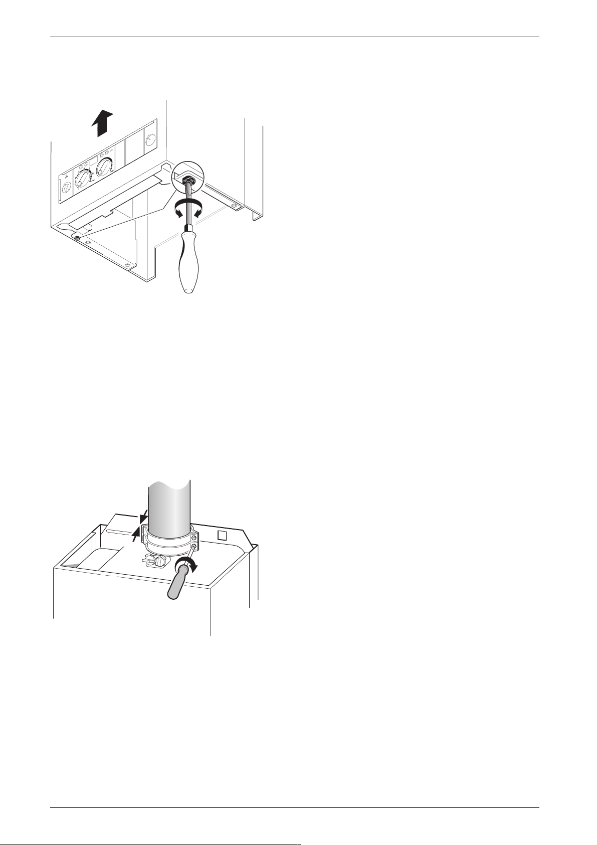
Removing the outer case
The outer case is secured against unauthorised removal by two clips (electrical
i
safety).
Always secure the outer case with those
clips again after refitting.
B Turn the clips with a screwdriver (1.).
B Slide the outer case upwards and then forwards to
remove (2.).
6 720 610 601 GB (03.02)
15
Page 16
Installation
1
B Remove the plastic caps from the boiler connec-
tions.
2.
1.
6 720 610 332-07.1R
Fig. 15
Fixing the appliance
B Fit the washers onto the gas and water connections.
B Lift the boiler onto the wall-mounting frame. The lugs
pass through the rectangular holes in the boiler back
panel.
B Take care not to disturb the washers on the connec-
tions.
Connecting the flue assembly
B Fit flue duct connector onto appliance flue spigot.
B Secure with the two screws supplied.
1 .
3
2
4
2 .
3.7 Checking the connections
Water connections
B Check that the O-rings or seals are in place before
tightening the connection.
B Turn on the service valves for central heating flow
and return and fill the heating system through a
WRAS approved filling loop.
B Check all seals and unions for leaks (testing pres-
sure max. 3.0 bar as indicated by pressure gauge).
B Check all connections for leaks.
Gas supply pipe
B Check that the seal is in place before tightening the
connection.
B Turn off gas cock to protect gas valve against dam-
age from excessive pressure.
B Check gas supply pipe.
B Release the pressure on the gas supply pipe.
3.8 Flue Systems
The only flue systems that may be used are those supplied with the boiler.
The flue system must be installed in accordance with
the requirements of BS 5440:1.
Standard 100 mm flue system
The standard concentric flue system provides for a horizontal length of upto 4 m. Full instructions for fitting this
flue are in Subsection 3.8.2 “Installation of the flue”.
Alternative 125 mm diameter flue systems
Installation instructions for the alternative flue
systems are sent with the appropriate flue kit.
Systems are available to give a maximum horizontal
length of 13 m.
A vertical flue system upto a height of 15 metres is available.
45° and 90° flue bends can be used with a corresponding reduction in flue length of 2 m for each 90° bend
and 1 m for each 45° bend used.
6 7 2 0 6 1 0 3 3 2 - 0 9 . 2 R
Fig. 16
B For remaining installation of flue assembly, refer to
the relevant installation instructions.
16
IMPORTANT: Any horizontal flue system fitted to a
condensing boiler must incline towards the appliance at
an angle of 3 % (30 mm per metre length) to prevent
condensate dripping from the flue terminal. This
means that the clearance above the appliance
must be increased to match the duct length.
Refer to fig. 1 on page 5.
6 720 610 601 GB (03.02)
Page 17
Installation
3.8.1 Siting the Flue Terminal
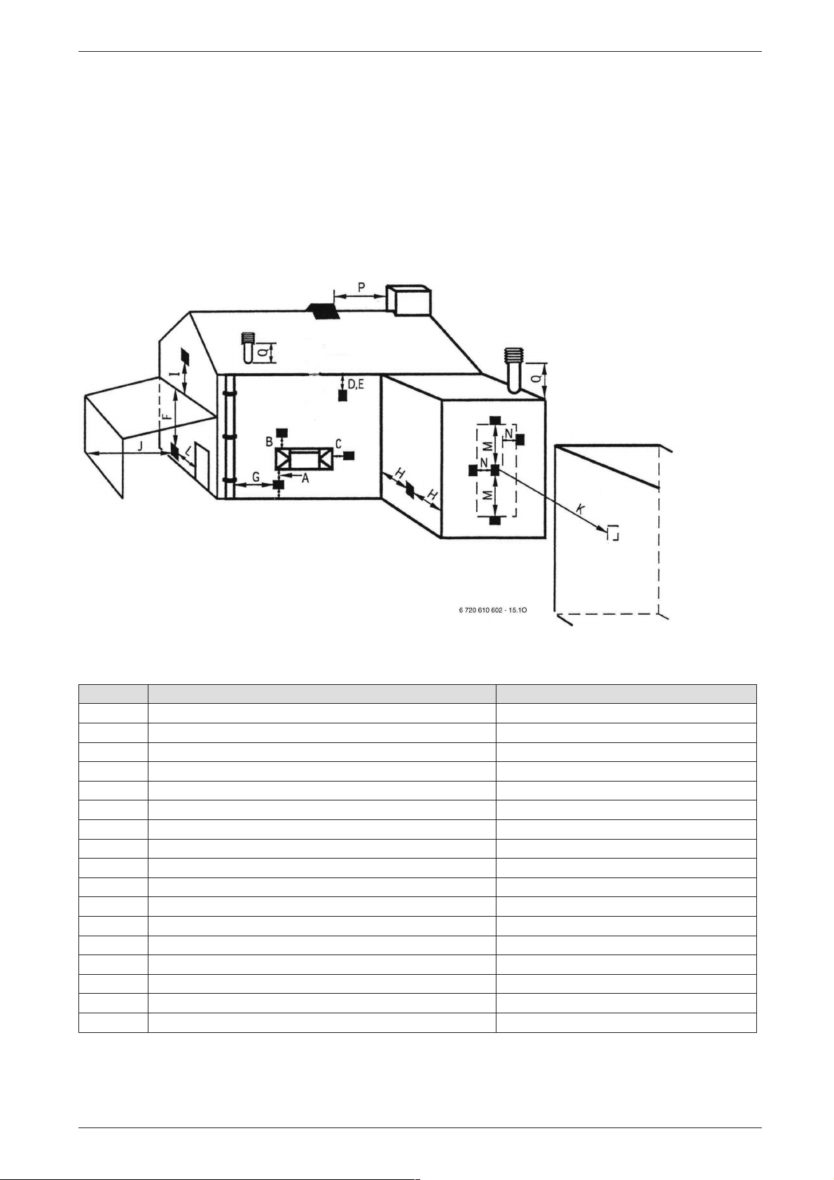
The flue must be installed in accordance with
BS 5440:1 and the Building Regulations. Flue terminals in carports and under balconies are to be avoided.
The terminal must be positioned so that it does not
cause an obstruction nor the combustion products a
nuisance. See fig. 17 and table 8.
The terminal will, at times, give out a plume of water
vapour and consideration must be given to this when
choosing a terminal position. Keep clear of security
lighting, activated by passive infra-red sensing heads.
If the terminal is less than 2 m above a surface to which
people have access then a guard must be fitted. The
guard must be evenly spaced about the terminal with a
space of 50 mm in each direction and fixed with plated
screws.
A guard Type K6 for the standard horizontal flue, can be
obtained from Tower Flue Components, Vale Rise, Tonbridge TN9 1TB.
Fig. 17
Minimum dimensions of flue terminal positions (all types) (see fig. 17)
Dimension Terminal Position (kW input expressed in net) Balanced flues room sealed: Fanned draught
1)
A
1)
B
1)
C
D Below gutters, soil pipes or drain pipes 75 mm
E Below eaves 200 mm
2)
F
G From a vertical drain pipe or soil pipe 150 mm
H From an internal or external corner 300 mm
I Above ground roof or balcony level 300 mm
J From a surface facing the terminal 600 mm
K From a terminal facing the terminal 1200 mm
L From an opening in the car port (e. g. door, window) into the dwelling 1200 mm
M Vertically from a terminal on the same wall 1500mm
N Horizontally from a terminal on the same wall 300 mm
O From the wall on which the terminal is mounted Not applicable
P From a vertical structure on the roof Not applicable
Q Above intersection with roof Not applicable
Directly below an opening, air brick, opening windows, etc. 300 mm
Above an opening, air brick, opening window, etc. 300 mm
Horizontally to an opening, air brick, opening window, etc. 300 mm
Below balconies or car port roof (lowest point) 200 mm
Table 8
1) In addition, the terminal should not be nearer than 150 mm (fanned draught) to an opening in the building fabric formed for the purpose of accommodating a built-in element such as a window frame.
2) Not recommended.
6 720 610 601 GB (03.02)
17
Page 18
Installation
3.8.2 Installation of the flue
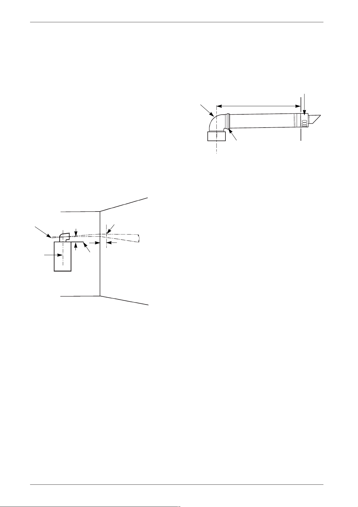
The standard 100 mm diameter horizontal flue system
is suitable for lengths upto 4 m.
Flues upto 650 mm do not require an extension duct
assembly.
Flues between 1600 mm and 4000 mm require extension duct assemblies.
NOTE: Flue lengths between 650 mm and 730 mm
cannot be accomodated. Refer to fig. 19, 20, 21.
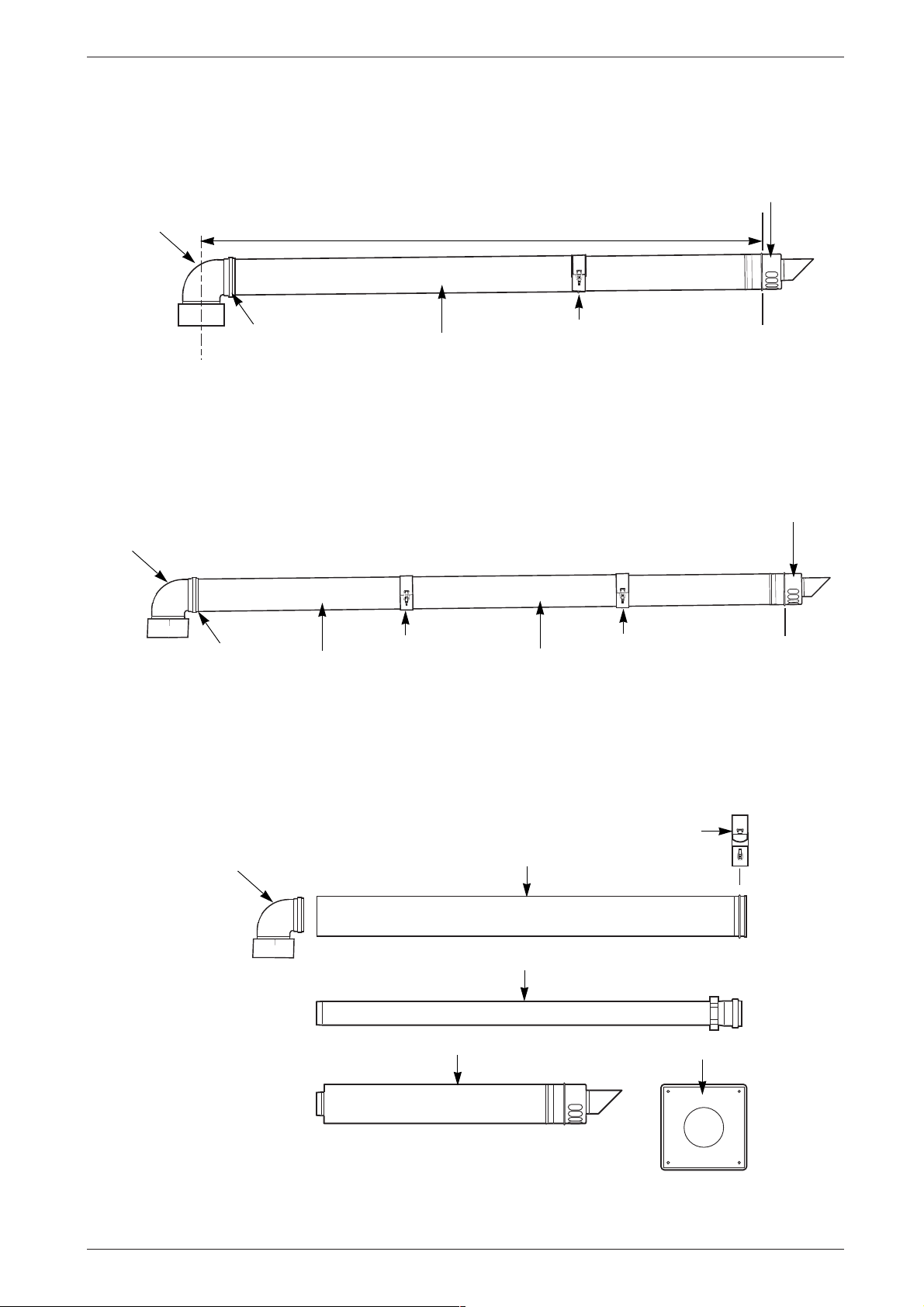
Standard system comprise: Flue turret - Flue turret
clamp - Terminal assembly - Wall sealing - plates.
Extension kit comprises: Air duct - Flue duct - Duct
clamp. Refer to fig. 22.
Instructions for fitting other flue systems are packed
with the relevant flue kit.
Check that the position chosen for the appliance is satisfactory. Refer to fig. 18.
Flue
Turret
Maximum 650 mm
No
Clamp
Terminal
Assembly
Outer
Wall
6 720 610 602 - 08.1O
Centre line of
flue/air duct
Centre
line of
flue
opening
and
appliance
Appliance
Standard Horizontal Flue 158 mm
Optional Horizontal Flue 121 mm
H
Top of the
wall
mounting
frame
H
Drilling point for
flue duct opening
120
3 %
(30 mm/metre)
6 720 610 602-07.2O
Fig. 18 Marking the position of the side flue opening
Fig. 19 Standard Flue
18
6 720 610 601 GB (03.02)
Page 19
Flue
Turret
No
Clamp
Fig. 20 Flue with one extension
Maximum 1600mm
Extension
Duct
Clamp
Installation
Terminal
Assembly
Outer
Wall
6 720 610 602 - 09.1O
Flue
Turret
No
Clamp
Fig. 21 Flue with extensions
Flue
Turret
Extension
Duct
Clamp
Extension
Duct
Extension Air Duct
Clamp
Terminal
Assembly
Outer
Wall
6 720 610 602 - 10.1O
Duct Clamp
Fig. 22 Flue components
6 720 610 601 GB (03.02)
Extension Flue Duct
Terminal Assembly
Wall Sealing Plates
6 720 610 602 - 11.1O
19
Page 20
Installation
3.8.3 Flue duct preparation and assembly
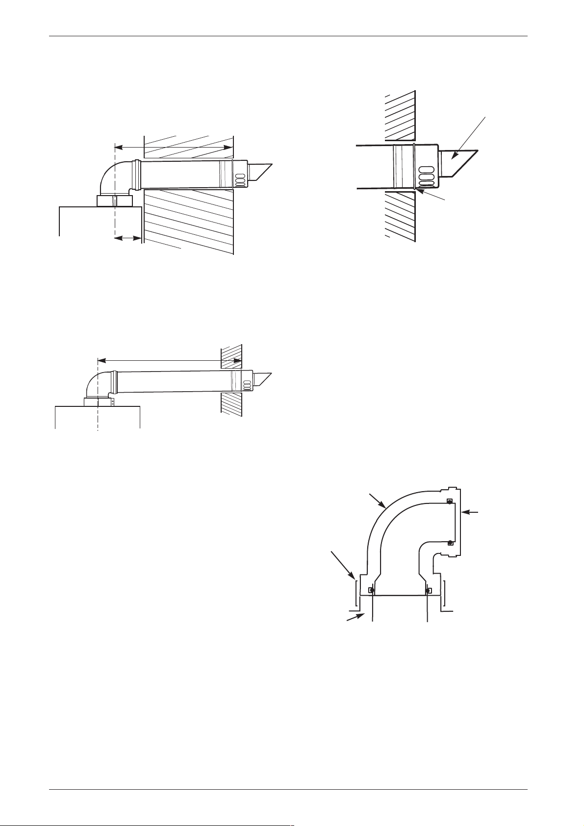
Measure the flue length L. Refer to fig. 23, 24.
L
120
Outer
Wall
Face
Flue Terminal
Raised Ring
locating the
terminal relative
to the outside
wall face
NOTE: THE FLUE MUST BE INCLINED T O THE
BOILER
6 720 610 602 - 12.1O
Fig. 23 Flue length - rear
L
NOTE: THE FLUE MUST BE INCLINED T O THE
BOILER
Fig. 24 Flue length - side
Mark off the lengths shown onto the ducts and cut to
length. The cuts must be square and free from burrs.
Terminal assembly outer (air) duct - L- 70 mm, inner
(flue) duct - L- 50 mm.The measurement is made from
the ridge at the terminal indicating the outer face of the
wall. Refer to fig. 25.
Extension air duct - L- 70mm, flue duct - L- 50 mm.
The measurement is from the formed end.
6 720 610 602 - 13.1O
6 720 610 576 - 20.1O
Fig. 25 Flue terminal position
Assemble flue system completely. Push the ducts fully
together and clamp in the positions. The slope of the
terminal outlet must face downwards.
The assembly will be made easier if a solvent free
grease is lightly applied i.e Vaseline, to the male end of
the ducts.
NOTE: An inner wall sealing plate is provided
which should be fitted to the ducts before assembly.
Push the assembly through the wall and fix the turret to
the appliance with the clamp. Refer to fig. 26.
Flue Turret
Air and
Flue Duct
Entry into
silicone
Clamp
rubber seals
20
Flue Socket
on Boiler
6 720 610 602 - 14.1O
Fig. 26 Flue turret
Ensure that the turret is fully entered into the socket on
the boiler. From the outside fix the outer wall plate to the
terminal and, after ensuring the duct is properly i nclined
towards the boiler, fix the plate to the wall.
If the terminal is within 2 m of the ground where there is
access then an approved terminal guard must be fitted.
The guard must give a clearance of at least 50 mm
around the terminal an be fixed with corrosion resistant
screws.
6 720 610 601 GB (03.02)
Page 21
Electrical connections
0
1
2
3
4
5
E
6 720 610 332 -11.1R
0
1
2
3
4
5
E
6 720 610 332-12.1R
13-14
10-12
8-9
5-7
L
N
N
LL
R
S
S
4130-14.1R
4 Electrical connections
B Always disconnect the power supply to
the appliance at the mains before carrying out any work on the electrical systems and components.
All control and safety systems are built into the appliance.
B Allow mains cable to protrude at least 50 cm from
wall.
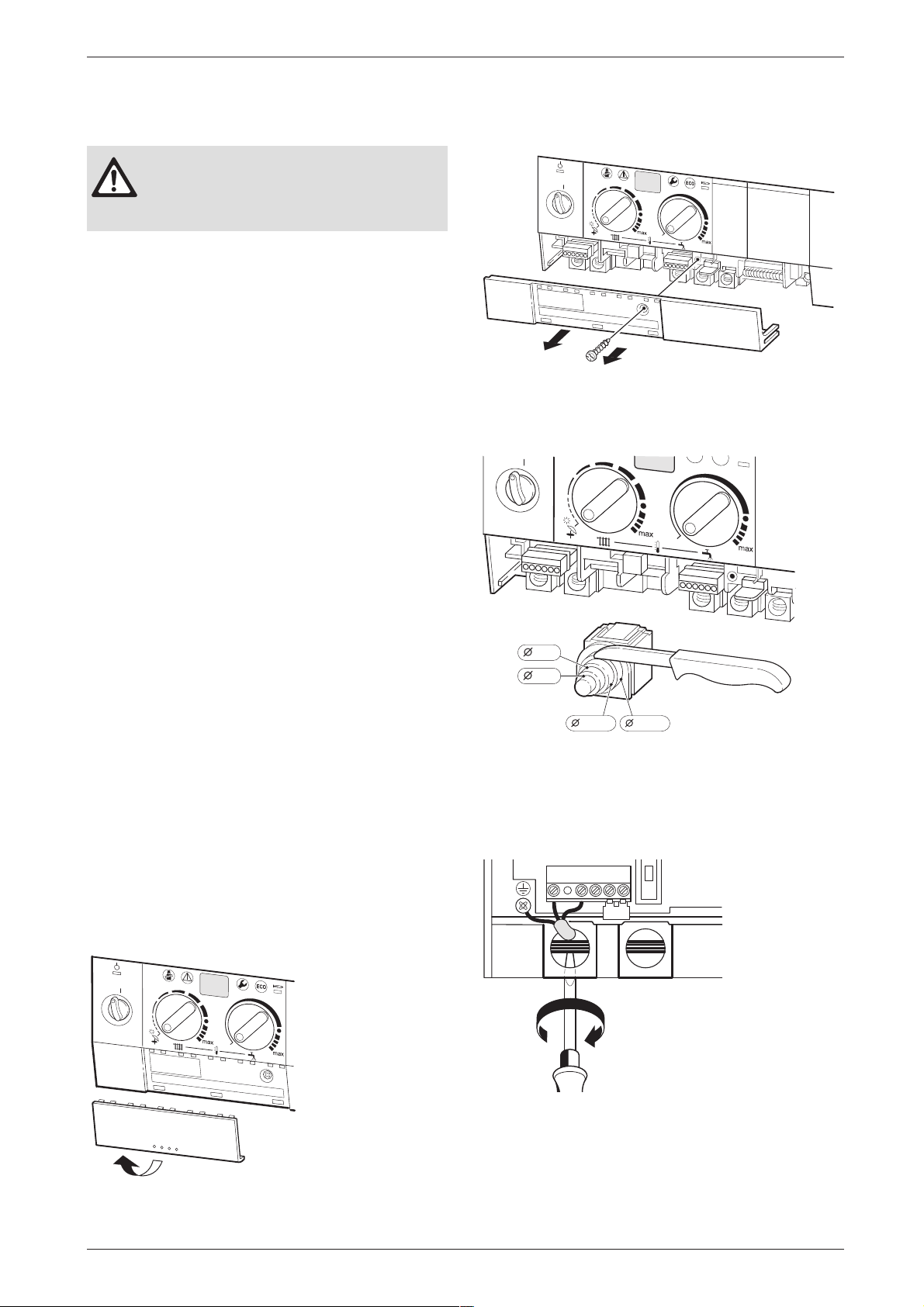
B To make splash-water proof (IP): cut the cable grom-
met hole size to match diameter of cable, see fig. 29.
It must be possible to isolate the appliance. The appliance must be earthed.
The appliance must be connected to the mains through
a 6 A double pole isolator with a contact separation
3 mm in all poles and supplying the appliance and controls only. The wiring must comply with the current
requirements of the IEE Wiring Regulations and any
local regulations which apply.
• Supply: 230 V ~ 50 Hz, 140 Watts
• Mains cable: PVC insulated 0.75 mm2
(24 x 0.20 mm) to BS6500-Table 6.
Temperature rated 100˚C.
• Protection IPX4D
• External fuse 3 A.
B Remove screw and slide terminal cover forwards to
remove. Refer to fig. 28.
Fig. 28
B Cut cable grommet to diameter of cable.
4.1 Connecting the appliance
To gain access to the mains connection remove the
drop down facia cover. The drop down cover is
removed by lowering it to the horizontal position and
pushing firmly upwards at the rear of the supports to
release the cover. Lift cover from the appliance.
After installation (or in the event of an electrical fault) the
electrical system shall be checked for short circuits,
fuse failure, incorrect polarity of connections, earth continuity and resistance to earth.
B Pull out cover panel at the bottom and remove. Refer
to fig. 27.
3
0
4
2
1
5
E
Fig. 29
B Feed cable through cable grommet and connect the
mains supply cable, see fig. 30.
B Secure cable in cable grommet by means of cable
grip.
Fig. 30
Fig. 27
6 720 610 601 GB (03.02)
6 720 610 332-10.1R
21
Page 22
Electrical connections
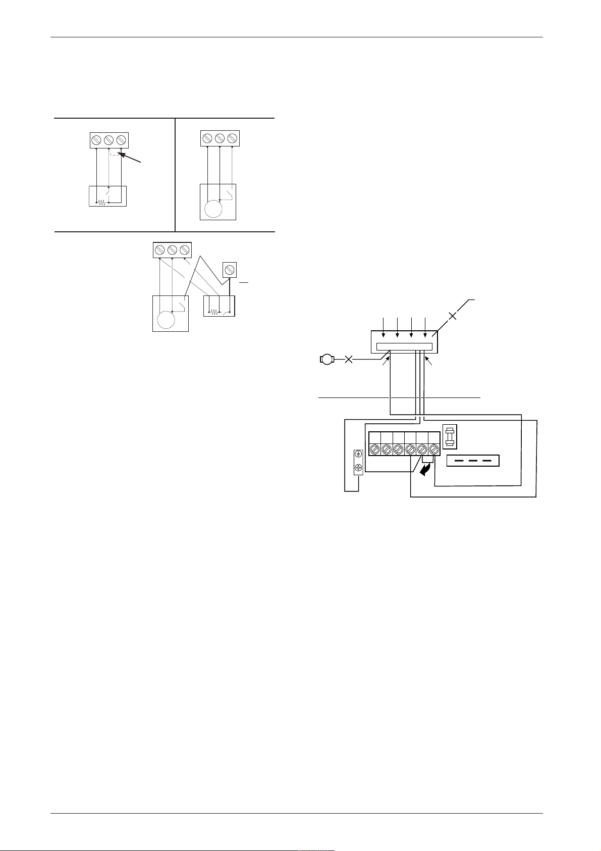
4.2 Mains Voltage external controls
connections
NOTE: Only double insulated controls not requiring an earth can be used
Ls
Ns
L
Ls
Ns
L
R
e
ched Liv
e
Neutral
Liv
Swit
230 V R
oom Thermostat Connections
230 V r
oom thermostat and
Programmer Connections
ST8
Remove Link
Ns
Neutral
Motor
Ls
Live
230 V Pr
L
R
e
iv
Swit
L
d
e
h
c
N
it
eutr
w
S
R
ST8
al
ched Live
Neutr
Swit
Live
Motor
ogrammer Connections
ST8
Series
connection
Live
e
6 720 610 576 - 22.1O
to be made
safe
ched Liv
al
Fig. 31
4.3 Wiring to your system
The following diagrams show the wiring options for your
system. Any other combinations of wiring are not recommended as it would increase complexity of the system. Please also follow wiring instructions of any
proprietary system. Worcester Heat Systems cannot
be held responsible for any incorrect wiring external
from the boiler.
Mains electrical supply: The boiler should be connected
to the mains supply as described in Section 4.1. This
also provides the electrical supply to the system. Note:
In all cases this must be the only electrical supply
to the system. This ensures the safety of a single
fused supply.
Pump: The boiler is fitted with an internal pump.
These diagrams show connection details of two popu-
lar proprietary systems (Honeywell and Siebe, formerly
ACL ), for systems from other manufacturers instructions or contact Worcester Technical Service 08705
266 241 for assistance.
Upon completion of the electrical connections check
for earth continuity, correct polarisation and resistance
to earth.
4.3.1 Pre-wired Remote S Plan
If the system is fully pre-wired at a juction box remotely
from the boiler, it can be easily connected back to the
boiler.
Drop down the facia and gain access to the boiler wiring centre as described in section 4.1.
Connect the junction box as shown (see fig. 32)
Important notes:
• Observe wiring details given in Section .
• Remove the pre-fitted link from LS and LR.
• If a room thermostat is required, it can be wired to the
remote junction box according to the proprietary
instructions.
• If a frost thermostat is required, it can be wired to the
remote junction box.
Permanent
Mains supply
(NOT ALLOWED)
Outside of Boiler
Inside of Boiler
6 720 610 603 -04.2O
RemotePre-wired
Junction Box
External pump
(DISCONNECT
AND REMOVE)
Boiler/pump
demand from
junction box.
Timer
Tank Stat
Terminal Strip
L out
LN
MAINS ONLY
NSLSL
Room Stat
System
Water
Valve/s)
ELN
Mains electrical supply to junction box
(NO OTHER SUPPLY TO
JUNCTION BOX ALLOWED)
R
Fig. 32
22
6 720 610 601 GB (03.02)
Page 23
15
27
61
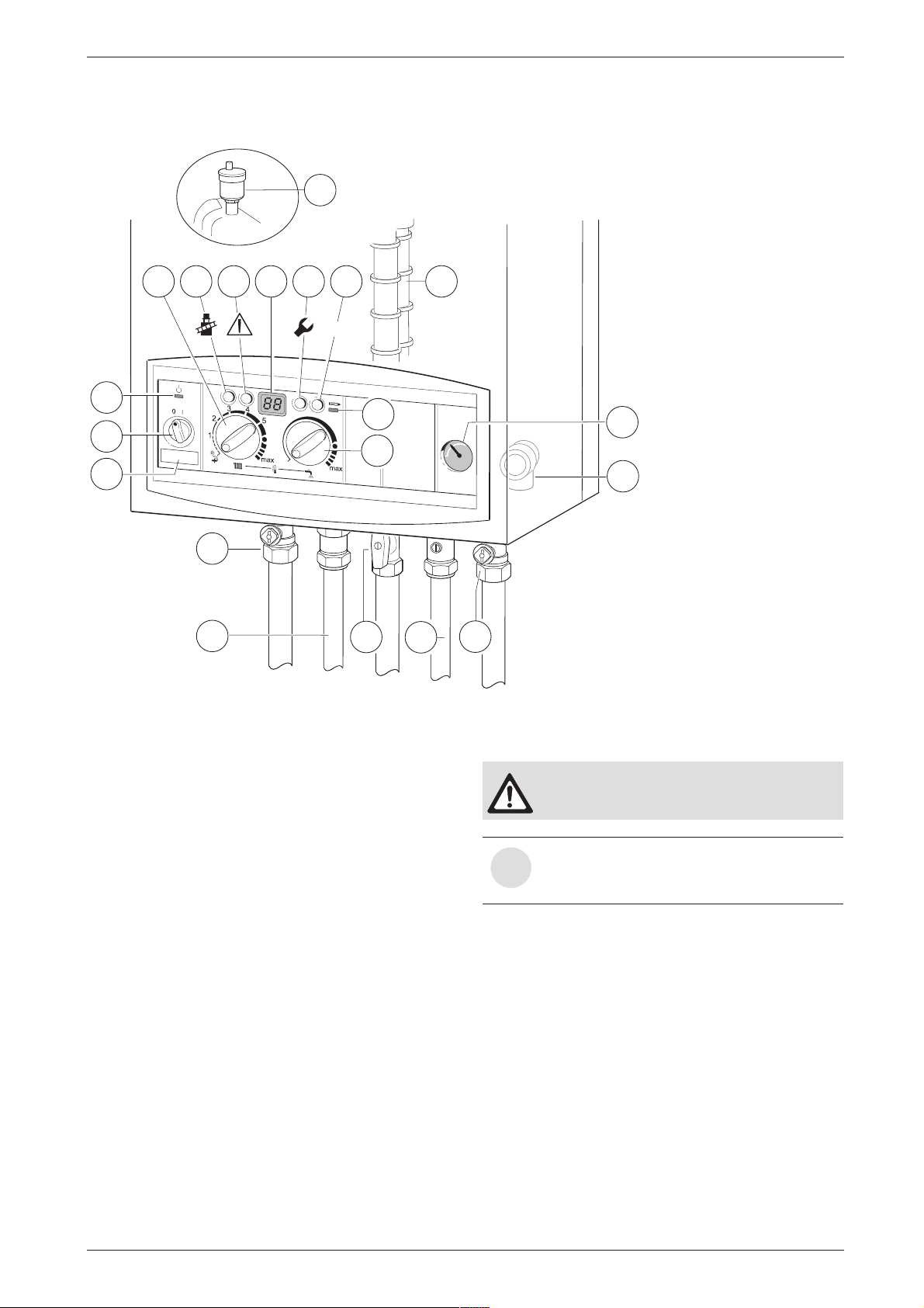
Commissioning
5 Commissioning
27
61
364
135
295
136
365
317 366 367
ECO
E
363
310
358
8.1
15
170
171
172
173
Fig. 33
8.1 Pressure gauge
Safety valve
Automatic vent
Reset button
135 Master switch
136 Temperature control for central heating
170 Service cocks on CH flow and return
171 Optional cylinder flow (used only with motorised valve)
172 Gas cock (shown in on position)
173 Optional cylinder return (used only with motorised valve)
295 Appliance type sticker
310 Temperature control for hot water
317 Multifunction display
358 Condensate trap
363 Indicator lamp for burner
364 Indicator lamp for power supply
365 “Chimney sweep” button
366 Service button
367 ECO button
170
6 720 610 576-07.2O
5.1 Commissioning
Never run the appliance when empty or
unpressurised.
The operational CO
tory and no adjustment is necessary when
i
installing a natural gas fired appliance.
Benchmark Water Treatment: For optimum performance after installation, this boiler and its associated central heating system should be flushed in accordance
with the guidelines given in BS 7593:1992 - Treatment
of water in domestic hot water systems. Full instructions are supplied with proprietary cleansers sold for
this purpose. If an inhibitor is to be used after flushing,
it should be used in accordance with the inhibitor manufacturers instructions.
To drain the appliance shut the system valves and open
the system drain point.
Suitable flushing agents and inhibitors are available from
Betz/Dearborn Tel.: 0151 4209563, Fernox Tel.:
01799 550811 and Salamander Tel.: 0121 378 0952.
Instructions for use are supplied with the these
products.
level is set at the fac-
2
6 720 610 601 GB (03.02)
23
Page 24
Commissioning
B Before commissioning, the gas supply pres-
sure must be checked at the gas supply pressure test point (see page 6, fig. 2, item 7).
Natural gas appliances must not be operated if
the gas supply pressure is below 18 mbar or
above 24 mbar. LPG appliances must not be
operated if the supply pressure is not 37 mbar
at the inlet to the appliance.
B Unscrew the condensation trap (358) and pull out,
fill with approx. 1/4 l of water and refit. Refer to
fig. 33.
B Adjust charge pressure of expansion vessel to static
head of the central heating system (see page 26).
B Open all system radiator valves.
B Turn on service valves (170), fill central heating sys-
tem to pressure of 1 - 2 bar through the WRAS
approved filling loop. Refer to fig. 33.
B Vent radiators.
B Refill heating system and set the pressure to 1 bar.
B Turn on cold water service cock (173). Refer to
fig. 33.
B Check that the gas type specified on the identifica-
tion plate matches that of the gas supply.
B Turn on gas cock (172). Refer to fig. 33.
Switching off the appliance
B Set the master switch to (0).
The green indicator lamp goes out.
B Always disconnect the appliance from
the power supply (fuse, circuit breaker)
before carrying out any work on the
electrical systems or components.
5.3 Switching on the central heating
The central heating flow temperature is adjustable
between 35˚C and 88˚C. Refer to table 11, page 26.
B Turn the temperature control to set the flow tem-
perature to a level appropriate to the type of central
heating system:
– Underfloor heating: e.g. setting “3”
(approx. 50˚C)
– Low-temperature heating: setting “E”
(approx. 75˚C)
– Central heating systems for flow temperatures up
to 88 °C: limited “max” setting for low-temperature
operation (see page 26).
When the burner is alight, the red indicator lamp
lights up.
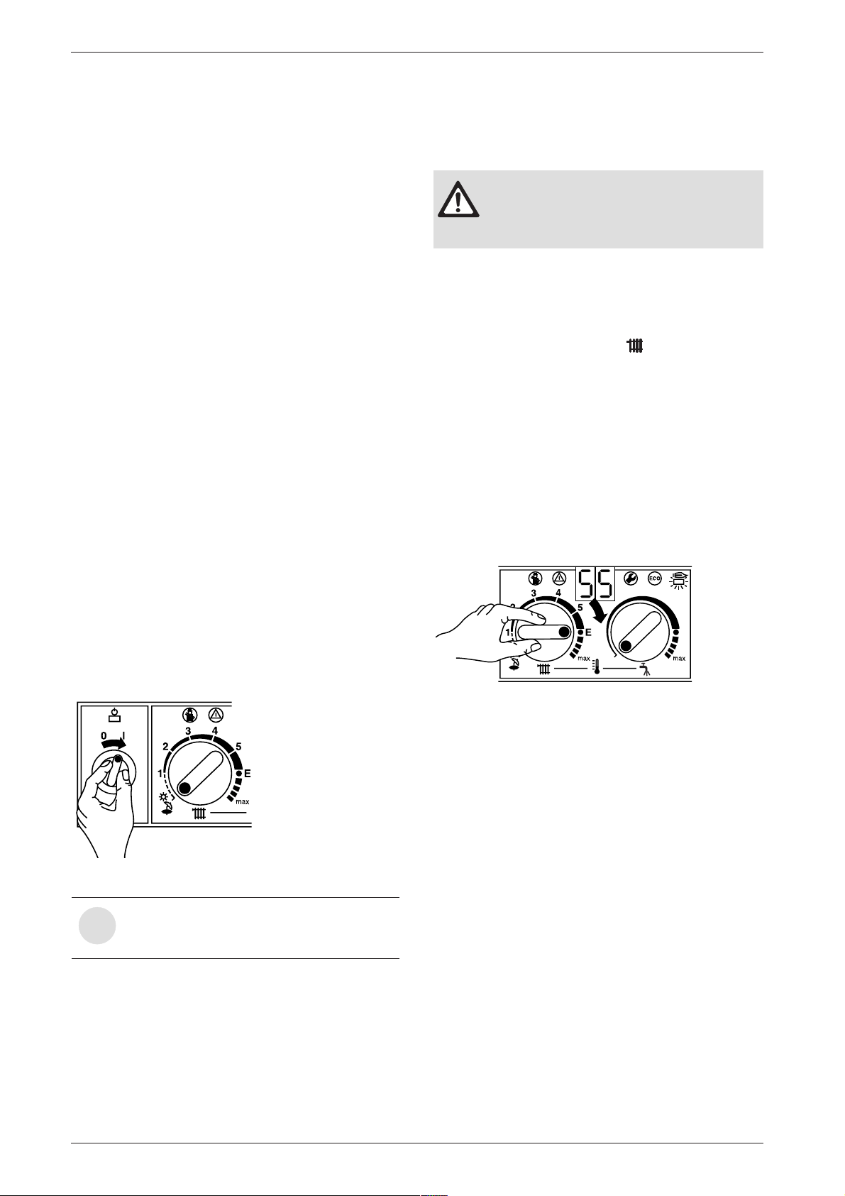
5.2 Switching the appliance on/off
Switching on
B Switch on the appliance at the master switch (I).
The indicator lamp shows green and the display will
show the central heating flow temperature, when the
appliance is operating in the central heating mode.
6 720 610 333-04.1O
Fig. 34
If the display alternates between -II- and
the central heating flow temperature, the
i
trap filling programme is active.
The trap filling programme ensures that the condensation trap is filled after the appliance has been installed
or after the appliance has been out of use for a long
period or the mains supply has been interrupted. For
that reason, the appliance remains at minimum heating
output for 15 minutes.
6 720 610 333-05.1O
Fig. 35
5.4 System controls
B Set room thermostat to the desired room tempera-
ture.
B Set outside - temperature driven control unit, if fitted.
Refer to the instructions with the control.
B Set the thermostatic radiator valves to the desired
settings.
24
6 720 610 601 GB (03.02)
Page 25
Commissioning
5.5 Appliances with optional plug-in
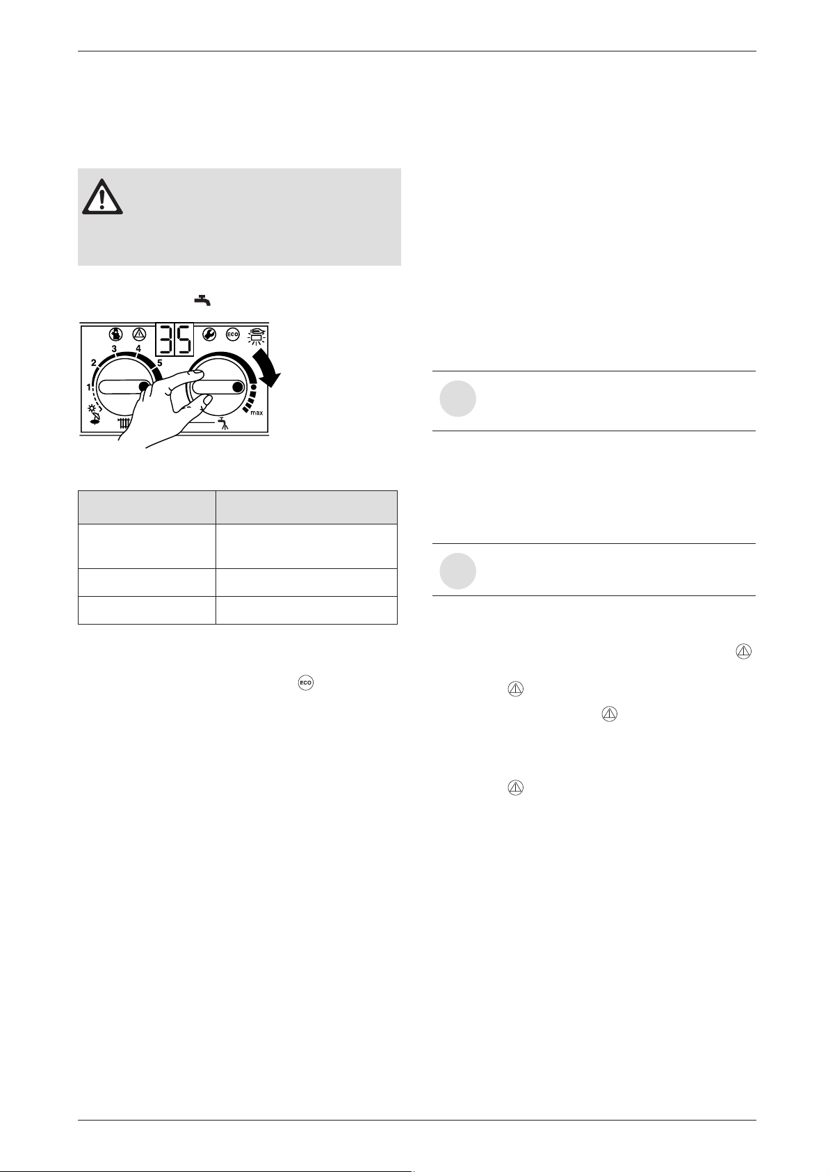
diverter valve: Setting hot water
temperature
B Do not set the temperature higher than
60˚C for normal operation.
B Only use temperatures of up to 70˚C
temporarily for thermal disinfection purposes.
B Set the hot water temperature by means of the tem-
perature control on the appliance.
6 720 610 333-07.1O
Fig. 36
Control Setting Water Temperature
Anti-clockwise limit approx. 10˚C
(frost protection)
approx. 60˚C
5.6 Frost protection
Frost protection is only guaranteed from the external
room temperature thermostat.
B Leave master switch switched on.
If the appliance is to be left for long periods switch the
central heating off:
B Add a suitable anti-freeze fluid to the water in the
central heating system.
Suitable products are available from Betz-Dearborn
Tel.: 0151 4209563 and Fernox Tel.: 01799
550811.
5.7 Pump anti-seize function
This function prevents the central heating
pump seizing after long periods of inactiv-
i
ity.
Every time the pump is switched off, a timer is started.
If after 24 hours the pump has not run again, it is
switched on for a period of 5 minutes.
5.8 Fault Condition
A list of faults that may occur is given on
page 41.
i
Clockwise limit approx. 70˚C
Table 9
ECO button
Pressing and holding the ECO button switches from
Comfort mode to ECO-mode.
Comfort mode, ECO button is not lit (factory setting)
Comfort mode the hot water tank has priority. The hot
water cylinder is first heated up to the set temperature.
The appliance then switches to central heating mode.
ECO mode, button is lit
In ECO mode the appliance switches between central
heating mode and cylinder charging mode every
12 minutes.
In the unlikely event of a fault occuring while the appliance is in operation:
The display then shows a fault code and the button
may also flash.
If the button flashes:
B Press and hold the button until the display shows
“– –”.
The appliance will then start up again and the display
will show the central heating flow temperature.
If the button does not flash:
B Switch the appliance off and then on again at the
master switch.
The appliance will start up again and the central heating flow temperature will be displayed.
6 720 610 601 GB (03.02)
25
Page 26
Individual settings
6 Individual settings
6.1 Mechanical settings
6.1.1 Checking the size of the expansion vessel
Maximum pressure at maximum CH flow temperature is
2.5 bar. If the pressure is greater than this then fit an
extra expansion vessel. Refer to table 10.
System Capacity – BS 7074:1
Expansion Vessel Pressure and System Capacity
Expansion Vessel litres 10
Expansion Vessel
Charge Pressure
System
pressure
and
capacity
1 bar litres 82
1.5 bar litres 46
Table 10
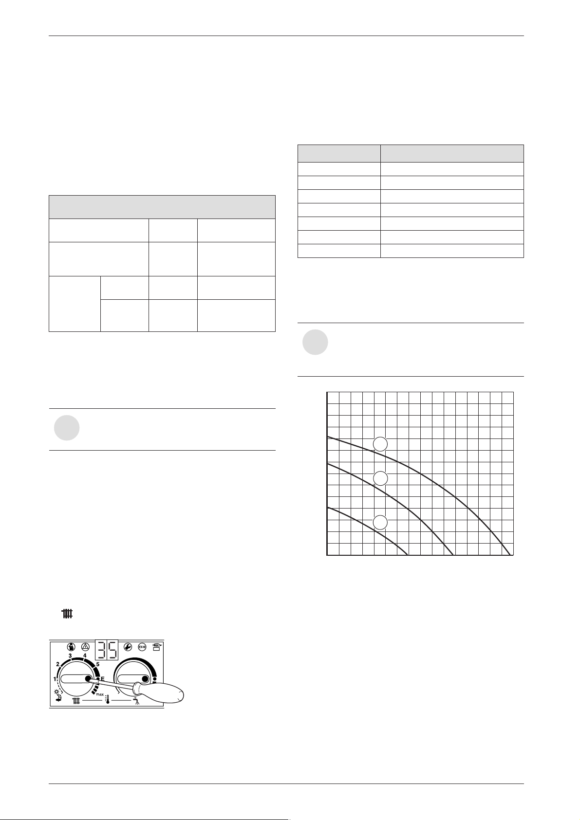
6.1.2 Setting the central heating flow temperature
The central heating flow temperature can be set to
between 50˚C and 88˚C.
With underfloor heating systems, observe
the maximum permissible flow tempera-
i
tures.
bar 0.75
B Rotate yellow button through 180° and replace (dot
facing inwards).
The CH flow temperature is no longer limited.
Control setting CH flow temperature
1 approx. 50˚C
2 approx. 55˚C
3 approx. 60˚C
4 approx. 65˚C
5 approx. 70˚C
E approx. 75˚C
max approx. 88˚C
Table 11
6.1.3 Changing the heating pump characteristic
The speed of the central heating pump can be altered
on the pump terminal box.
At switch position 1, maximum output is
not delivered if hot water mode is active.
i
Position 1 must not be used on combi appliances.
0,7
H
(bar)
0,6
0,5
3
Limited maximum setting for low-temperature
operation
The temperature control is factory limited to setting E,
giving a maximum flow temperature of 75˚C.
Adjustment of the heating output to the calculated heat
demand is not required by the heating systems regulations.
Removing the maximum setting limit
For heating systems which require higher flow temperatures, the maximum setting limit can be removed.
B Lift off the yellow button on the temperature control
with a screwdriver.
6 720 610 332-27.1O
Fig. 37
0,4
0,3
0,2
2
1
0,1
0
200 400 600 800
0
Fig. 38
1 Pump characteristic for switch position 1
2 Pump characteristic for switch position 2
3 Pump characteristic for switch position 3
H Residual delivery pressure
Q Water circulation rate
1200
6 720 610 576-23.2O
14001000 1600
(l/h)
Q
26
6 720 610 601 GB (03.02)
Page 27
Individual settings
6.2 Settings on the Bosch Heatronic
6.2.1 Operating the Bosch Heatronic
The Bosch Heatronic enables easy setting and checking of a large number of appliance functions.
This description is limited to those functions required
for commissioning.
For a full description of all available functions, please
refer to the Service booklet for the Engineer, order no.
7 181 465 346.
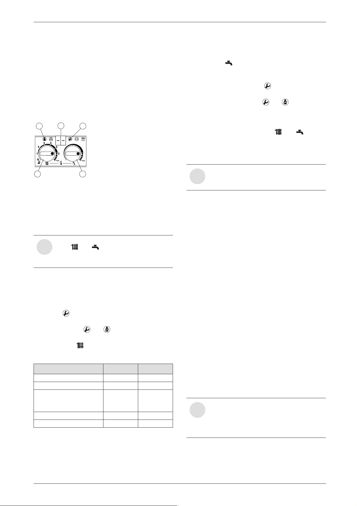
2 1
3
Fig. 39 Appliance controls
1 Service button
2 “Chimney sweep” button
3 Temperature control for central heating
4 Temperature control for hot water
5 Display
Selecting service function:
The service functions are subdivided into two levels:
Level 1 comprises service functions up to function 4.9,
while Level 2 consists of the service functions from 5.0
upwards.
B To select a service function on Level 1: press and
hold the button until the display shows – –.
B To select a service function on Level 2: press and
hold the buttons and simultaneously until the
display shows = =.
B Then turn the temperature control to select the
required function.
Service function Code no. See page
Pump control mode 2.2 27
Anti-cycle time 2.4 27
Max. CH flow
temperature
Switching difference 2.6 28
Max. heating output 5.0 28
Table 12
The service function 5.0 may be reset.
5
6 720 610 332-30.1O
4
Note the positions of the temperature controls and . After completing the set-
i
tings, return the temperature controls to
their original positions.
2.5
28
Entering a setting
B To enter the setting for a function, turn the tempera-
ture control .
Storing a setting
B Level 1: press and hold the button until the dis-
play shows [ ].
B Level 2: press and hold the and buttons simul-
taneously until the display shows [ ].
After completing the settings
B Reset the temperature controls and to their
original positions.
6.2.2 Selecting the pump control mode for central heating mode (Service Function 2.2)
If an outside temperature driven control
unit is connected, pump control mode 3 is
i
automatically activated
The choice of settings is as follows:
• Control Mode 1
For heating equipment without a control unit.
The pump is controlled by the central heating flow
temperature control.
• Control Mode 2 (factory setting)
For heating systems with room thermostat.
The central heating flow temperature control controls
only the gas, the pump is not affected. The room thermostat controls both the gas and the pump.
The pump and fan have an overrun time of between
15 s and 3 min.
• Control Mode 3
The pump is controlled by the outside temperature
driven control unit. In summer mode, the pump operates only for hot water mode.
6.2.3 Setting the anti-cycle time
(Service Function 2.4)
This service function is only active if Service Function
2.7, automatic anti-cycle time, is deactivated.
The anti-cycle time can be set to between 0 and 15 minutes (is factory set to 3 minutes).
If the setting 0 is entered, the anti-cycle time is inactive.
The shortest possible anti-cycle time is 1 minute (rec-
ommended for single-pipe and hot-air heating systems).
If the appliance is connected to an outside-temperature controlled heating pro-
i
grammer, the anti-cycle time does not
need to be set on the appliance and is optimised by the programmer instead.
6 720 610 601 GB (03.02)
27
Page 28
Individual settings
6.2.4 Setting the maxim CH flow temperature
(Service Function 2.5)
The maximum CH flow temperature can be set to
between 35˚C and 88˚C (factory setting).
6.2.5 Setting the switching difference
(Service Function 2.6)
If the appliance is connected to an outside-temperature controlled programmer,
i
the programmer sets the switching difference.
It does not need to be set on the appliance.
The switching difference is the permissible divergence
from the specified CH flow temperature. It can be set in
increments of 1 K. The adjustment range is 1 to 30 K (is
factory set to 0 K). The minimum CH flow temperature
is 30˚C.
6.2.6 Setting the heating output
(Service Function 5.0)
The heating output can be set to any level between min.
rated heat output and max rated heat output to limit it to
the specific heat requirements.
The full rated heat output is still available
for hot water or charging the hot water cyl-
i
inder even if the heating output has been
limited.
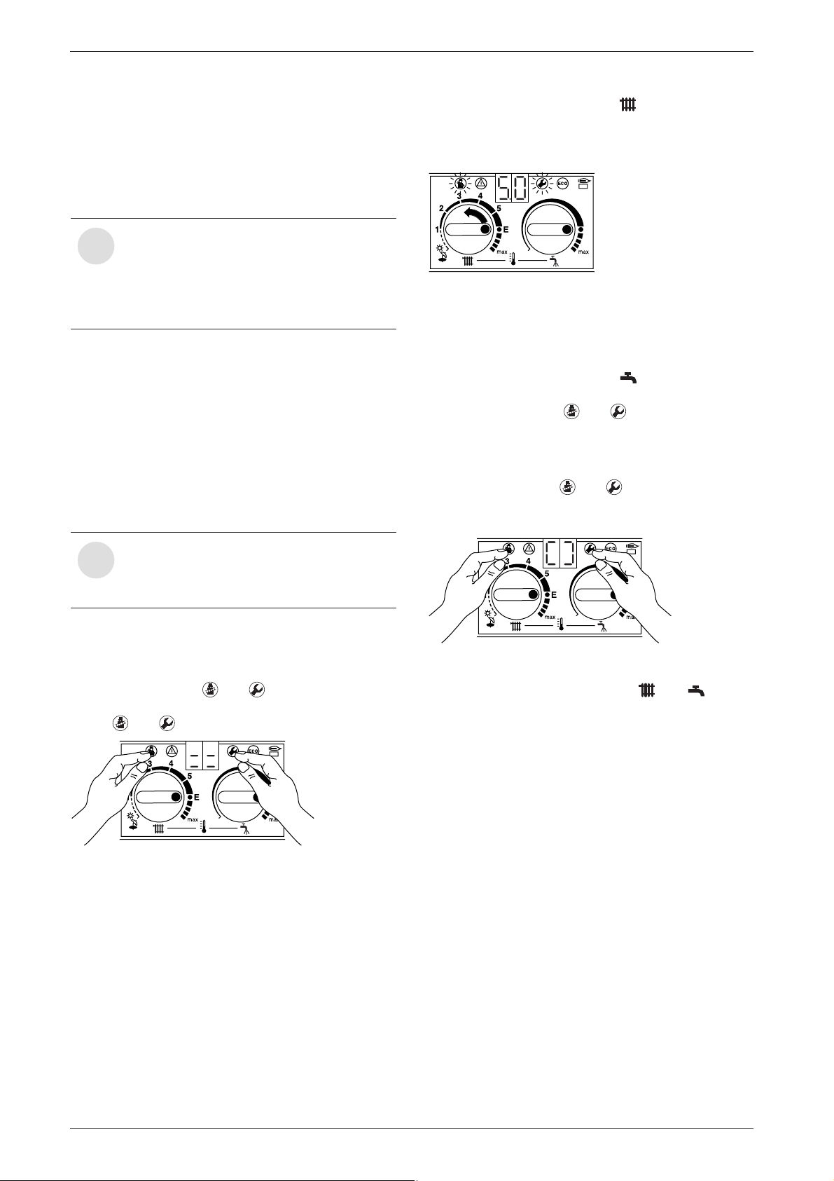
B Turn the temperature control until the display
shows 5.0.
After a short delay, the display then shows the set
heating output in percent.
6 720 610 332-51.1O
Fig. 41
B Refer to the settings tables for heating and cylinder
charging output to obtain the relevant code for the
desired heating output in kW (see page 42).
B Turn the temperature control until the display
shows the desired code number.
The display and the and buttons will flash.
B Measure the gas flow rate and compare with the fig-
ures specified for the code number displayed. If figures do not match, adjust the code number!
B Press and hold the and buttons simultane-
ously until the display shows [ ].
The heating output is now stored.
The factory setting is the max. rated heat output.
B Set the room thermostat and thermostatic radiator
valves to max. temperature.
B Press and hold the and buttons simultane-
ously until the display shows = =.
The and buttons will light up.
6 720 610 332-50.1O
Fig. 40
6 720 610 332-52.1O
Fig. 42
B Return the temperature controls and to their
original positions.
The display will revert to the CH flow temperate.
6.3 Setting the gas/air ratio
The appliance is set at the factory and adjustment is not
necessary.
28
6 720 610 601 GB (03.02)
Page 29
Converting the appliance to different gas types
6 7 2 0 6 1 0 3 3 2 - 5 7 . 2 R
2 3 4
6 720 610 332-60.1O
7 Converting the appliance to different gas types
The setting is factory sealed at maximum. Adjustment to
the rated heat input and min. heat input is not necessary.
Checking the gas supply pressure
B Check the gas supply pressure at the gas supply
pressure testing point.
Natural gas appliances must not be operated if the gas supply pressure is below
i
18 mbar or above 24 mbar.
LPG appliances must not be operated if
the supply pressure is below or above
37 mbar.
Natural gas
• Appliances for natural gas type G20 are factory set
to Wobbe-Index 15 kWh/m3 and 20 mbar supply
pressure and sealed.
Conversion kits
For conversion
Model
from ... Order no.
7.1 Setting the gas/air ratio
The gas/air ratio may only be adjusted on the
basis of a CO2 measurement at max. heat output
and min. heat output using an electronic tester.
B Switch off the appliance at the master switch (O).
B Remove the outer case (see page 16, refer to
fig. 15).
B Switch on the appliance at the master switch (I).
B Set room thermostat to maximum temperature.
B Open thermostatic radiator valves.
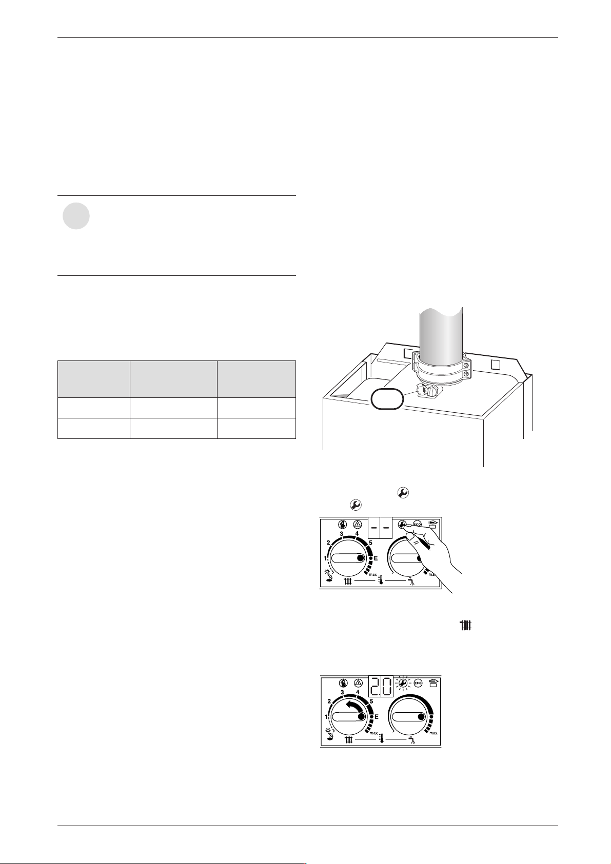
B Unscrew sealing plug from flue gas testing
point (234). Refer to fig. 43.
B Insert testing probe about 135 mm into the flue gas
testing point and seal testing point.
ZB 7-28 N.G to L.P.G 7 710 149 049
ZB 11-28 L.P.G to N.G 7 710 239 085
Table 13
• Instructions are sent with each conversion kit.
Fig. 43
B Press and hold button until the display shows – –.
The button will light up.
6 720 610 332-32.1O
Fig. 44
B Turn the temperature control until the display
shows 2.0 .
After a short delay, the current operating mode setting will be displayed (0. = Normal mode).
6 720 610 601 GB (03.02)
Fig. 45
29
Page 30
Converting the appliance to different gas types
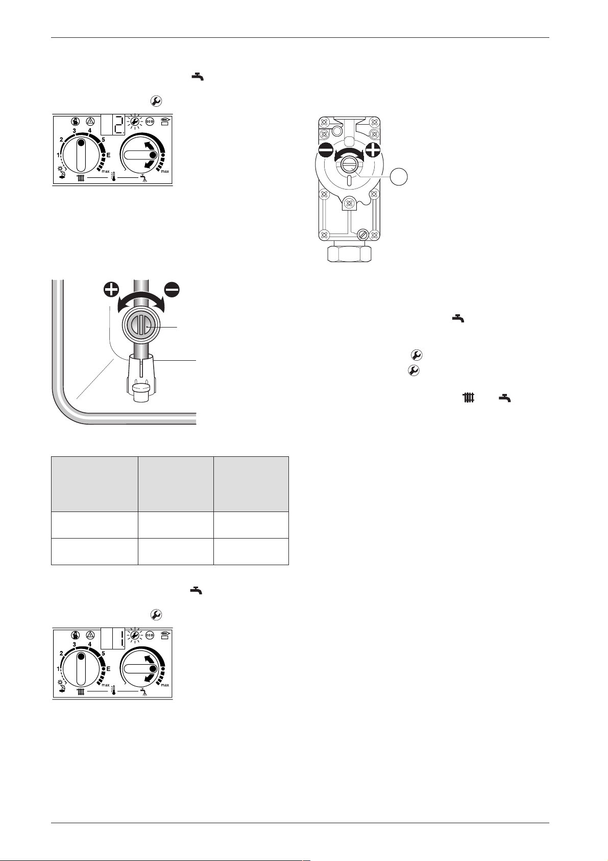
B Turn the temperature control until the display
shows 2. (= max. rated heat output).
The display and the button will flash.
6 720 610 332-61.1O
Fig. 46
B Measure the CO2 level.
B Prise off the seal on the gas flow restrictor.
B Adjust the gas flow restrictor (63) to obtain the CO2
level given in Table 14. Refer to fig. 47.
63
6 720 610 332-64.1R
Fig. 47
CO2 reading
at max.
rated heat
Gas Type
Natural gas type
output
9.2 % 8.8 %
G20
LPG G31
10.8 % 10.5 %
(propane)
Table 14
B Turn the temperature control anti-clockwise until
the display shows 1. (= min. rated heat output).
The display and the button will flash.
CO2 reading
at min. rated
heat output
B Remove the seal from the gas valve adjusting
screw (64) and adjust the CO2 level to the figure
given in Table 14 for min. rated heat output.
64
3928-74.1R
Fig. 49
B Recheck the levels at min. and max. rated heat output
and re-adjust if necessary.
B Turn the temperature control anti-clockwise as
far as the stop so that the display shows 0.
(= Normal operating mode).
The display and the button will flash.
B Press and hold the button until the display
shows [ ].
B Reset the temperature controls and to their
original positions.
The display will revert to the CH flow temperature.
B Remove testing probe from the flue gas testing
point (234) and refit sealing plug.
B Re-seal gas valve adjusting screw and gas flow
restrictor.
B Replace outer case and secure.
B Set room thermostat and thermostatic radiator valves
to the desired temperature.
6 720 610 332-63.1O
Fig. 48
B Measure the CO2 level.
30
6 720 610 601 GB (03.02)
Page 31
Converting the appliance to different gas types
7.2 Testing combustion air/flue gas at set heat output
7.2.1 Testing the O2 or CO2 level in the combus-
tion air
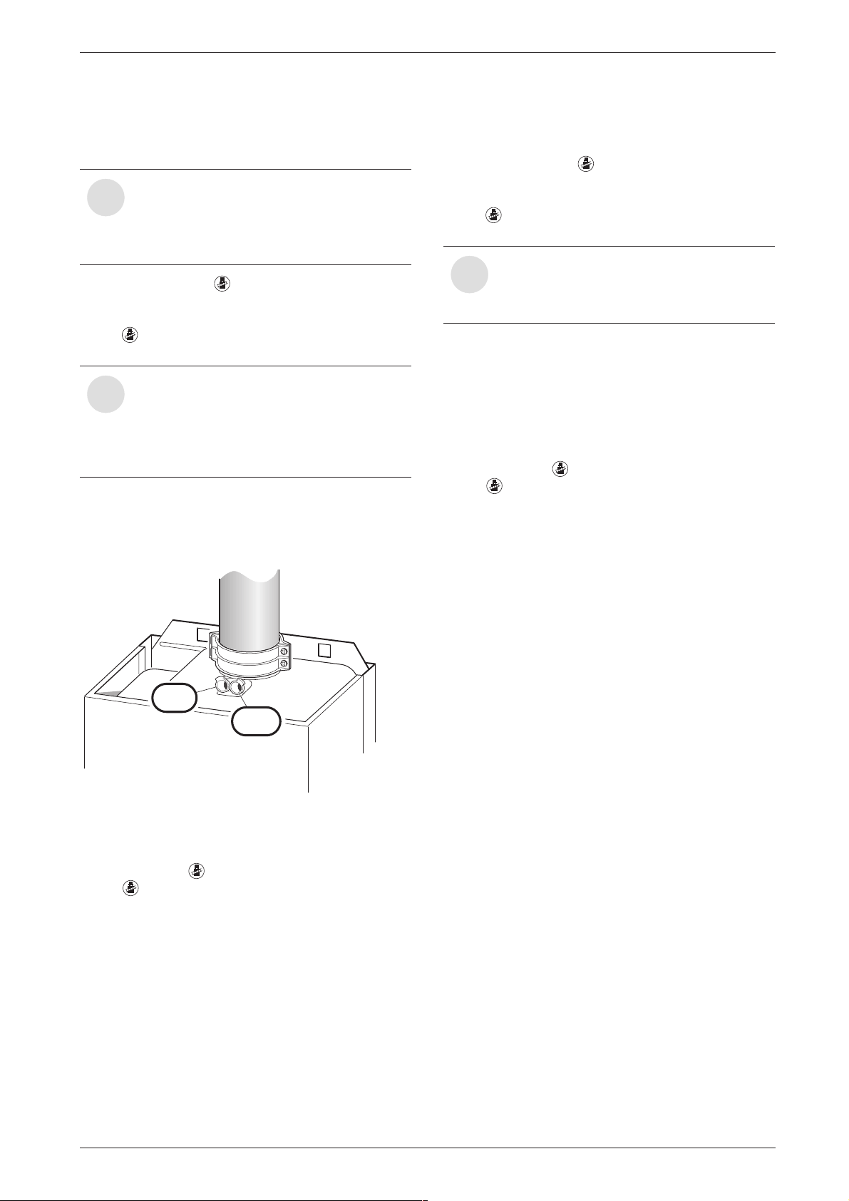
By testing the O2 or CO2 level in the combustion air the gas tightness of a type C13
i
or C33 flue system can be checked. The
O2 level must not be less than 20,6 %.
The CO2 level must not exceed 0,2 %.
B Press and hold the button until the display
shows – –.
“Chimney sweep” mode is now active.
The button will light up and the display shows the
CH flow temperature.
In “chimney sweep” mode, the appliance
switches to max. rated heat output or the
i
set heating output. You then have 15 minutes in which to measure the levels. After
that, the appliance switches back from
“chimney sweep” mode to normal mode.
B Remove sealing plug from combustion air testing
point (234.1, Fig. 50).
B Insert testing probe about 80 mm into the testing
point and seal testing point.
7.2.2 Testing CO and CO
B Press and hold the button until the display
shows – –.
“Chimney sweep” mode is now active.
The button will light up and the display shows the
CH flow temperature.
You have 15 minutes in which to measure
the levels. After that, the appliance switch-
i
es back from “chimney sweep” mode to
normal mode.
B Remove sealing plug from flue gas testing point
(234, fig. 50).
B Insert testing probe about 135 mm into the testing
point and seal testing point.
B CO- and CO2 levels.
B Refit sealing plug.
B Press and hold button until the display shows – –.
The button will stop flashing and the display
shows the CH flow temperature.
2
2 3 4
2 3 4 . 1
6 7 2 0 6 1 0 3 3 2 - 6 5 . 2 R
Fig. 50
B Measure O2 and CO2 levels.
B Refit sealing plug.
B Press and hold button until the display shows – –.
The button will stop flashing and the display
shows the CH flow temperature.
6 720 610 601 GB (03.02)
31
Page 32
Maintenance
8 Maintenance
B Always disconnect the appliance from
the electrical power supply (fuse, circuit
breaker) before carrying out any work on
the electrical systems or components.
B Always turn off the gas cock before car-
rying out any work on components
which carry gas.
There is a special Service booklet for the
Engineer, order no. 7 181 465 346, avail-
i
able to competent persons.
All safety and control systems are monitored by the Bosch Heatronic. In the event
i
of a component fault, the display shows a
fault code.
B The User should be recommended to have the appli-
ance serviced regularly by a competent person (see
Maintenance Contract).
B Use only genuine spare parts
B Refer to the Spare Parts List when ordering spare
parts.
B Always renew seals and O-rings removed during
servicing or repair work.
B Use only the following types of grease:
– Water valve: WRAS approved silicon based
grease
– Unions: approved sealant.
B To drain the appliance shut the system valves and
open the pressure relief valve.
B To drain the appliance shut the system valves and
open the pressure relief valve.
B Upon completion of any electrical work check for
earth continuity, correct polarisation and resistance
to earth.
32
6 720 610 601 GB (03.02)
Page 33

8.1 Pre-Service Check List
1 Call up the last fault stored by the
Bosch Heatronic, Service Function .0,
(see page 34).
2 Check ionisation current, Service
Function 3.3, (see page 34).
3 Perform visual check of air/flue
duct.Visual check of diaphragm for
soiling and splits (see page 36).
Maintenance
Date
4 Check gas supply pressure
(see page 29).
5 Test combustion air/flue gas
(see page 31).
6 Check CO2 setting for min./
max. (gas/air ratio)
(see page 29).
7 Check gas and water systems for
leaks (see page 16).
8 Check heat exchanger
(see page 34).
9 Check burner (see page 35).
10 Clean condensation trap
(see page 35).
11 Check charge pressure of
expansion vessel matches
static head of heating system.
12 Check central heating system
pressure.
mbar
min. %
max. %
mbar
mbar
mbar
13 Check electrical wiring for damage.
14 Check heating programmer settings.
15 Check appliances that are part of
the heating system.
Table 15
6 720 610 601 GB (03.02)
33
Page 34
Maintenance
8.2 Description of servicing operations
The combustion performance must be checked before
and after any servicing work on the combustion and
burner components. Refer to section 7.2.
Check “Last fault stored”:
B Select Service Function .0 (see page 27 “Selecting
service function”).
There is a list of the fault codes in the Appendix (see
page 41).
To delete “Last fault stored”:
B Turn temperature control anti-clockwise as far as
the stop.
B Press and hold the button until the display
shows [ ].
The last fault stored has now been deleted.
Checking the ionisation current,
Service Function 3.3
B Select Service Function 3.3 (see page 27 “Select-
ing service function”).
B Remove the fan and the burner as described in the
text headed “Burner” (see page 35).
6 720 610 332-72.1R
Fig. 52
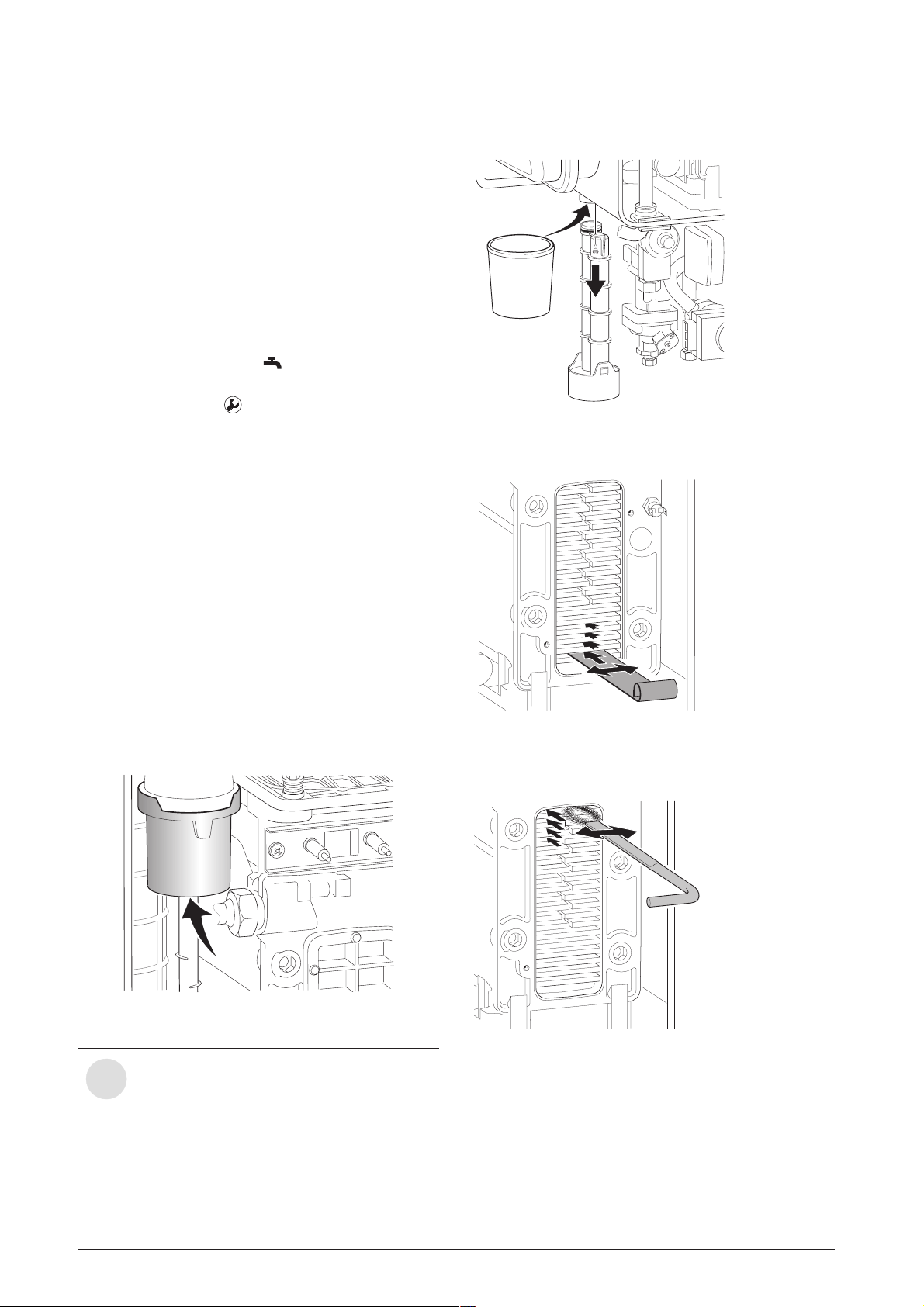
B Loosen any deposits in the heat exchanger from top
to bottom using the cleaning blade. Refer to fig. 53.
If the display shows 2 or 3, the ionisation current is OK.
If the display shows 0 or 1, the electrode assembly
(32.1, page 6) must be cleaned or replaced.
Primary Heat exchanger
There is a special accessory kit (no. 840) for cleaning
the heat exchanger, order no. 7 719 001 996.
B Check control pressure on the air - gas mixer unit at
max. rated heat output using an electronic manometer.
6 720 610 332-69.1R
Fig. 51
The heat exchanger should only be
cleaned if the control pressure is
i
2.2 mbar (depression) or less.
6 720 610 332-73.1R
Fig. 53
B Clean the heat exchanger from top to bottom using
the brush. Refer to fig. 54.
6 720 610 332-74.1R
Fig. 54
B Flush the heat exchanger from the top. Refer to
fig. 55.
B Remove cleaning access cover (415, page 6) and
the metal plate below it, if present. Refer to fig. 2.
B Unscrew condensation trap and place suitable con-
tainer underneath. Refer to fig. 52.
34
6 720 610 601 GB (03.02)
Page 35
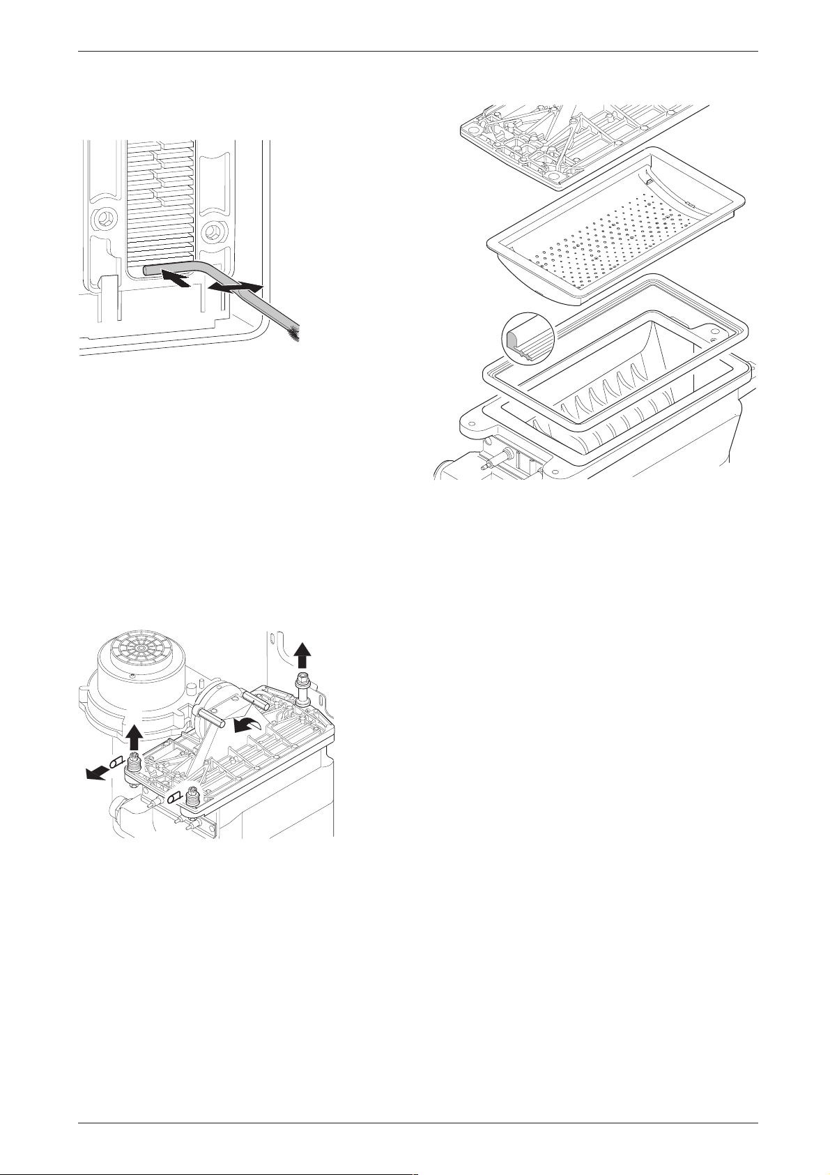
B Clean out the condensate collector and trap connec-
7 181 465 330-08.1R
tion (with other end of brush).
6 720 610 332-75.2R
Fig. 55
B Refit the clean-out cover using a new seal and
tighten screws to torque of approx. 5 Nm.
Maintenance
Burner
B Check that the gas cock is turned off and the master
switch is in the OFF position.
B Remove the clips (1.) and unscrew the two bolts (2.).
Refer to fig. 56.
B Unscrew and remove the two hexagon screws secur-
ing the fan (3.).
B Slacken fully the rear securing bolt (4.).
B Remove the burner coverplate.
4.
2.
3.
1.
7 181 465 330-04.1R
Fig. 56
B Remove the burner skin and clean components. Do
not use a wire brush. Refer to fig. 57.
Fig. 57
B Re-assemble burner in reverse order using a new
seal.
B Adjust gas/air ratio. Refer to section 7.2.
Condensation trap
In order to prevent spillage of condensate, the condensation trap should be completely removed, (see
page 34, fig. 52).
B Unscrew condensation trap and check connection
to heat exchanger is clear.
B Remove condensation trap cover and clean.
B Fill condensation trap with approx. 1/4 l of water and
refit.
Electrode assembly
B Switch off the master switch.
B Pull off the leads from the electrodes. Refer to fig. 2.
B Unscrew the two fixing screws and carefully remove
the electrode assembly. Refer to fig. 51.
B Clean the electrodes with a non-metallic brush. (The
spark gap should be 4 mm ± 1 mm.)
B Replace and re-connect the assembly taking care
not to mislay the inspection window.
6 720 610 601 GB (03.02)
35
Page 36
Maintenance
6 720 610 602
- 16.
1O
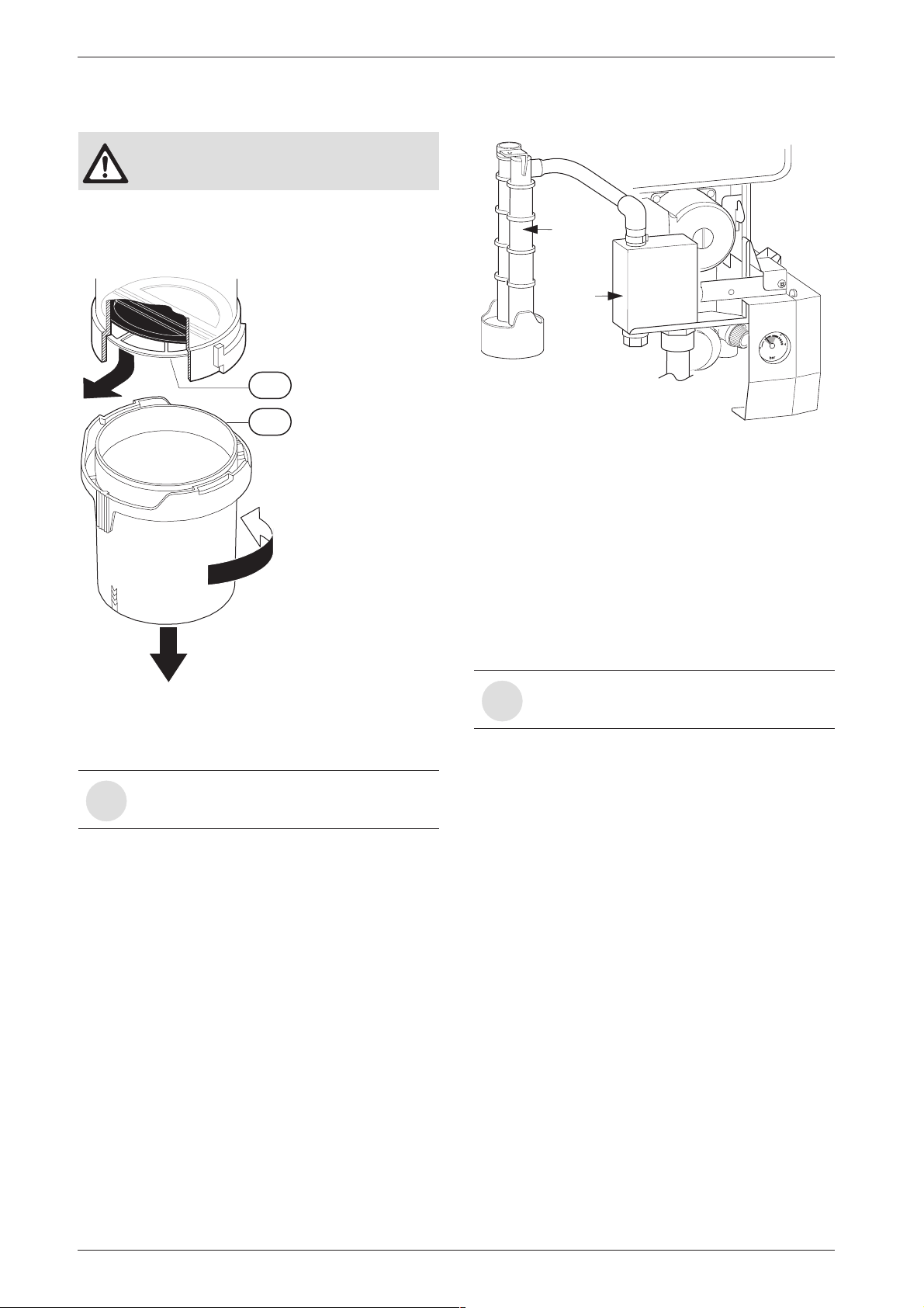
Siphon
Condensate
Drain
Diaphragm in mixer unit
B Take care not to damage diaphragm
(443) when removing and refitting it.
B Open mixer unit (29).
B Carefully withdraw diaphragm (443) from fan intake
tube and check for soiling and splits.
3.
443
29
1.
B Refit and prime the siphon.
Fig. 59
Expansion vessel
The expansion vessel should be checked once a year.
2.
6 720 610 790-07.2R
Fig. 58
B Carefully refit diaphragm (443) the correct way
round into the fan intake tube.
The flaps of the diaphragm (443) must
open upwards.
i
B Seal the mixer unit (29).
Siphon
B Unscrew the clip and disconnect the pipe to the
siphon.
B Remove the yellow plug to drain the siphon.
B Unscrew the securing nut from beneath the side
facia and remove the siphon. Refer to figure below.
B Depressurise appliance.
B If necessary, adjust expansion vessel charge pres-
sure to static head of the heating system.
Heating system pressure
Fill the system using the WRAS approved
filling loop.
i
B The pointer on the pressure gauge should be 1 bar.
B If the pointer is below 1 bar (when the system is
cold), water should be added until the pointer is
1 bar again.
B Max. pressure of 2.5 bar when the heating system
water is at maximum temperature must not be
exceeded. If this pressure is exceeded then an extra
expansion vessel must be fitted in the system return
as close to the appliance as possible.
B If the system does not retain the pressure, the expan-
sion vessel and the heating system should be
checked for leaks.
Electrical wiring
B Check the electrical wiring for physical damage and
replace any damaged wires.
36
6 720 610 601 GB (03.02)
Page 37
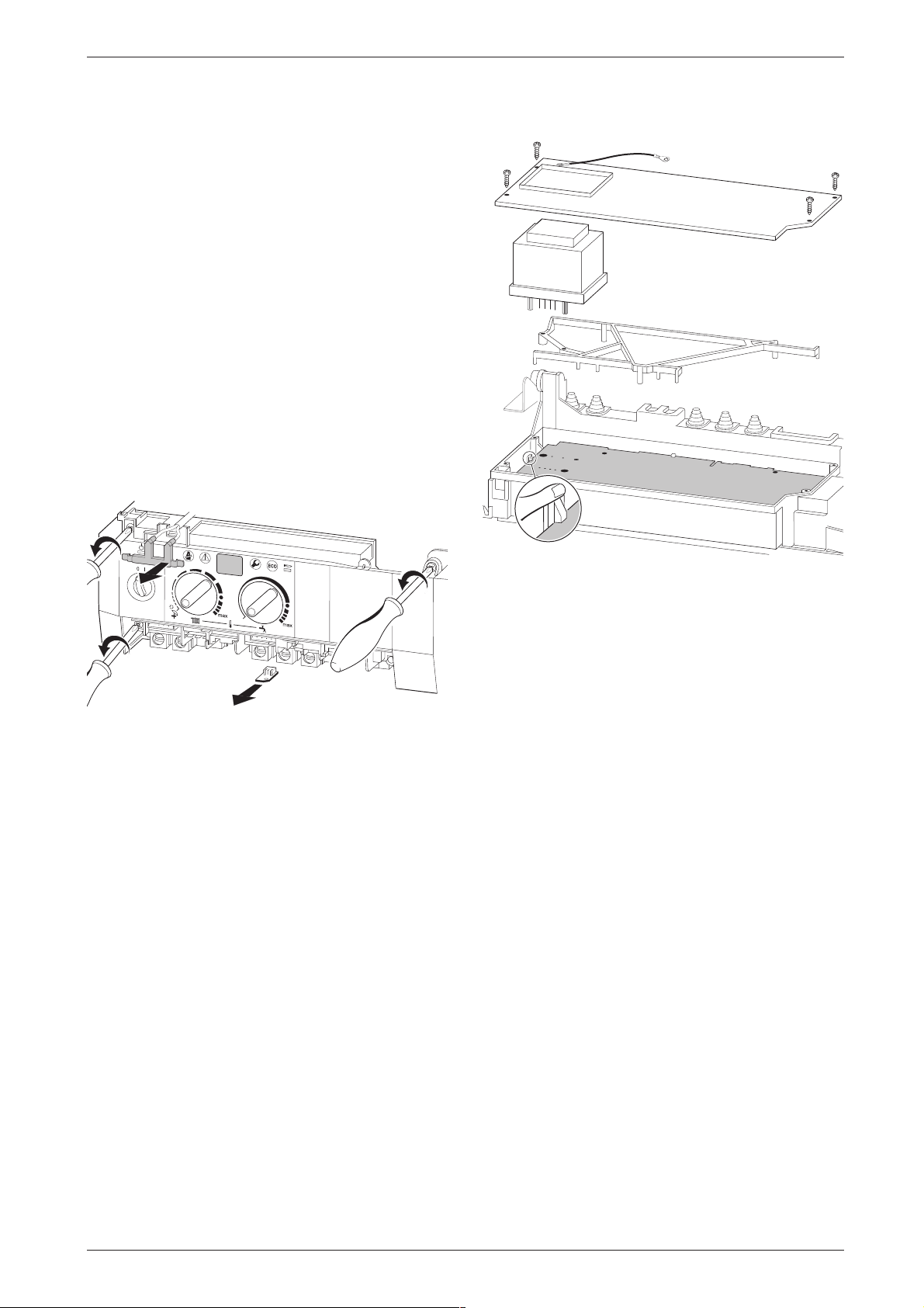
Maintenance
7 181 465 329
02.1R
1
1
1
7 181 465 330-10.1R
8.3 Replacement of Parts
Before changing any components check that the gas is
turned off and that the appliance is electrically isolated.
When necessary close the system valves and drain the
appliance.
Refitting is a reverse of the procedure for removal using
new seals or o-rings as appropriate.
8.3.1 PCB control board and transformer
B Switch off the appliance.
B Disconnect appliance from the power supply.
B Unplug all connectors from the control box (inc.
keyed plug). Access is gained by removing the covers. Refer to fig. 27, 28.
B Remove screw holding power connector earth lead
and remove earth lead.
B Remove two top fixing screws from the control box.
Refer to fig. 60.
3
2
4
3
4
2
1
3
2
4
5
E
3
2
4
B Remove the pcb control board.
Fig. 61
Fuses
B Remove the connections covers. Refer to fig. 27,
-
28.
The fuses are located adjacent to the mains connector
block and connector ST18. Refer to fig. 4.
Fig. 60
B Lower the control box.
B Unscrew earth lead.
B Unscrew four fixing screws from cover plate. Refer to
Fuse, item 312, is only replaceable by removing the
pcb.
Spare fuses are fixed to the connections cover.
A fuse pack is available: Part number 8 744 503 010 0.
fig. 61.
B Prise off cover plate.
B Pull off transformer.
B Remove pcb holder.
6 720 610 601 GB (03.02)
37
Page 38
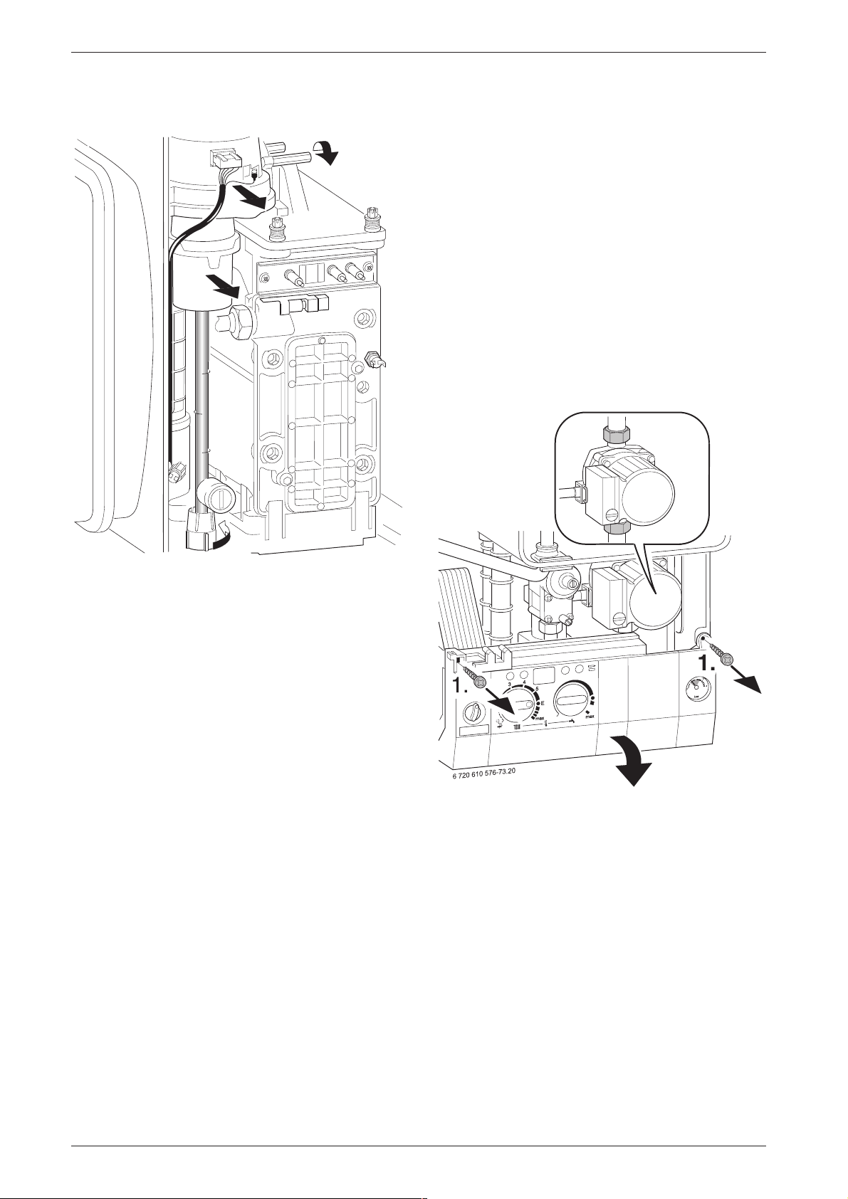
Maintenance
8.3.2 Fan Assembly
4.
2.
3.
8.3.3 Pump
B Switch off the appliance.
B Disconnect appliance from the power supply.
B Remove two switchbox fixing screws (1.). Refer to
fig. 63.
B Lower switchbox (2.).
B Unscrew and remove the siphon by releasing the
jubilee clip. Refer to fig. 59.
B Unscrew the pump union nuts (3). Refer to fig. 63.
B Carefully remove the pump and disconnect the
leads.
Alternatively
B After removing the siphon release the four Allen
screws and remove and replace the pump head.
3.
1.
Fig. 62
B Switch off the appliance.
B Disconnect the appliance from the power supply.
B Undo lower pipe union on gas pipe (1.). Refer to
fig. 62.
B Remove fan lead and earth connector (2.). The earth
connector has a positive clip fixing.
B Remove fixing screws attaching fan to the burner
cover (3.).
B Remove fan together with gas pipe and mixer unit.
B Separate the fan from the pipe and mixer unit by
twisting the mixer unit to release it (4.).
7 181 465 330-05.1R
1.
1.
2.
Fig. 63
8.3.4 3-way diverter valve
B Switch off the appliance.
B Disconnect appliance from the power supply.
B Turn off service cocks.
B Unplug connector from 3-way valve motor. Refer to
fig. 64.
B Pull out retaining clip.
B Remove motor.
B Disconnect the relief valve drain.
B Disconnect the pressure gauge by withdrawing the
clip and pulling out the capillary head.
B Undo pipe unions by withdrawing the clips.
38
6 720 610 601 GB (03.02)
Page 39
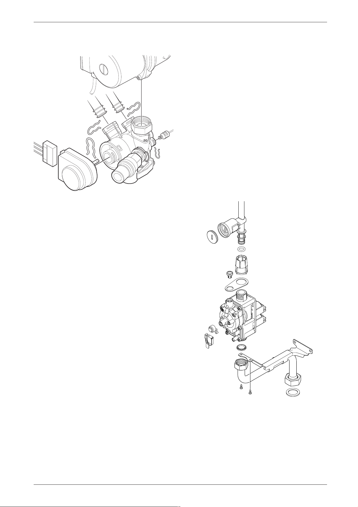
Maintenance
R
B Remove 3-way valve.
Fig. 64
After refitting:
8.3.7 Gas Valve
B Check that the gas cock is turned off.
B Lower the control panel. Refer to fig. 63.
B Pull off the solenoid connections at the rear of the
valve.
B Undo the union, within the inner casing, securing the
valve to the gas/air tube. Refer to fig. 62.
B Remove the white plastic cap from the gas valve.
B Release the gas inlet union at the manifold assembly.
B Unscrew the two screws securing the gas valve
assembly bracket to the back panel and withdraw the
assembly.
B Transfer the bracket and inlet pipe assembly to the
new gas valve.
B Check for gas soundness when the new gas valve
has been fitted.
B Recheck the combustion performance as described
in section 7.1.
7 181 465 330-12.1
B Fill system, bleed and re-pressurise
(see Installation Instructions).
8.3.5 3-way diverter valve motor
B Switch off the appliance.
B Turn off the service cocks.
B Unplug connector from 3-way valve motor. Refer to
fig. 64.
B Pull out retaining clip.
B Remove motor.
8.3.6 Sensors
B Check that the appliance is electrically isolated.
Central Heating Flow Temperature Sensor –
Item 36, fig. 2, 60
B Pull-off the connector.
B Release the sensor clip and withdraw the sensor.
B Apply heat transfer paste to the replacement sensor.
Safety Temperature Limiter – Item 6, fig. 2, 60
B Pull-off the connectors.
B Unscrew the sensor.
Flue Temperature Limiter – Item 9, fig. 2, 60
B Pull-off the connectors.
B Unscrew the sensor.
6 720 610 602 - 04.1O
Fig. 65
8.3.8 Electrode assembly
B Refer to section 8.2.
B Use a new seal if the existing seal is damaged.
6 720 610 601 GB (03.02)
39
Page 40

Maintenance
8.3.9 Pressure gauge
B Drain the appliance.
B Lower the facia. Refer to fig. 63.
B Twist the pressure gauge head anti-clockwise to
release it from the casing. Refer to fig. 2.
B Disconnect the capillary head from the rear by with-
drawing the clip and pulling out the head. Refer to
fig. 57.
8.3.10 Expansion vessel
B Drain the appliance.
B Undo the union connection at the base of the vessel.
Refer to fig. 2.
B Unscrew the top and bottom fixing screws and
remove the vessel.
B Set the pressure of the new vessel to that required
by the system.
8.3.11 Pressure Relief Valve
B Drain the appliance.
B Disconnect the drain pipe from the valve. Refer to
fig. 33.
B Pull-out the clip securing the valve.
B Pull-out the valve.
B Ensure that the replacement valve is fully entered
before fitting the clip.
B Ensure that all the seals are in place and all of the
connections are tight before re-commissioning the
appliance.
8.3.12 Burner
B Refer to section 8.2.
8.3.13 Primary Heat Exchanger
B Drain the appliance.
B Check that the gas supply is turned off.
B Check that the appliance is electrically isolated.
B Remove the fan assembly complete with the gas/air
tube and mixer assembly. Refer to section 8.3.2.
B Remove the burner. Refer to section 8.2.
B Disconnect the sensors. Refer to section 8.3.6.
B Undo the central heating flow union.
B Undo the top connection of the pump. Refer to
fig. 57.
B Undo the grey plastic cap, next to the top pump con-
nection at the base of the heat exchanger.
B Unscrew and remove the condensate trap. Refer to
section 8.2.
B Unscrew and remove the two screws securing the
heat exchanger top bracket to the rear panel.
B Lift up the flue duct, item 271, refer to fig. 2.
B Pull forward from the top and lift the heat exchanger
from the casing.
B Transfer components, as necessary, to the new heat
exchanger.
6 720 610 602 - 06.10
Fig. 66
40
6 720 610 601 GB (03.02)
Page 41
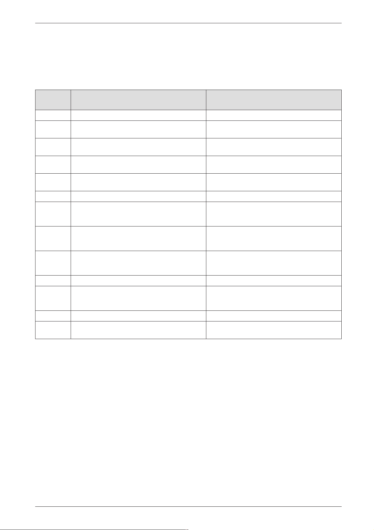
Appendix
9 Appendix
9.1 Fault Codes
More detailed fault finding procedures are described in the Service booklet for the Engineer number 7 181 465 346.
Display
code
A8 Break in communication Check connecting lead to programmer
AC Module not detected. Check connecting lead between TA211E/TR212E
b1 Keyed plug not detected. Insert keyed plug correctly, test and replace if neces-
C1 Fan speed too low. Check fan lead and connector, and fan; replace as
d3 Jumper 8-9 not detected. Connector not connected, link missing, underfloor
E2 CH flow NTC sensor defective Check CH flow NTC sensor and connecting lead.
Description Remedy
and Heatronic
sary.
necessary.
heating limiter tripped.
E9 Safety temp. limiter in CH flow has tripped. Check system pressure, check safety temp. limiters,
check pump operation, check fuse on pcb, bleed
appliance.
EA Flame not detected. Is gas cock turned on? Check gas supply pressure,
power supply, igniter electrode and lead, ionisation
sensing electrode and lead, flue duct and CO
F0 Internal error. Check electrical connector contacts, programmer
interface module ignition leads are not loose; replace
pcb if necessary.
F7 Flame detected even though appliance switched off. Check electrode assembly, dry pcb. Flue clear?
FA Flame detected after gas shut off. Check gas valve and wiring to gas valve. Clean con-
densation trap and check electrode assembly. Flue
clear?
Fd Reset button pressed by mistake. Press reset button again
P1, P2,
P3, P1...
Please wait, initialisation in progress. 24 V fuse blown. Replace fuse.
level.
2
Table 16
6 720 610 601 GB (03.02)
41
Page 42
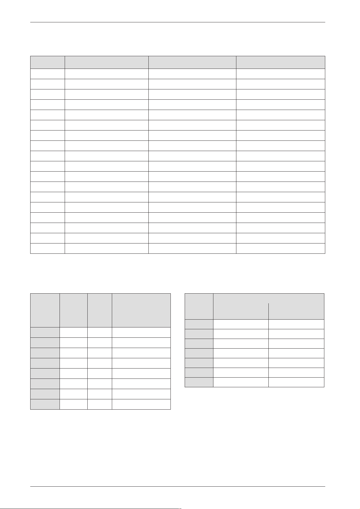
Appendix
9.2 Short parts list
Key Description Qty GC Spare part number
1 Sensor - Flue gas temp. 1 8 729 000 144 0
2 Sensor - CH flow temp. 1 8 714 500 087 0
3 Control board 1 8 748 300 418 0
4 Gas valve 1 8 747 003 516 0
5 Fan assembly 1 8 717 204 373 0
6 Fan washer 1 8 729 000 183 0
7 Expansion vessel 1 8 715 407 236 0
8 Relief valve 1 8 717 401 012 0
9 Electrode assembly 1 8 718 107 077 0
10 Electrode lead 1 8 714 401 999 0
11 Pump 1 8 717 204 384 0
12 Pressure gauge 1 8 717 208 079 0
13 Burner skin seal 1 8 711 004 168 0
14 Transformer - facia 1 8 747 201 358 0
15 Heat exchanger washer 1 8 710 103 153 0
16 Washer set Condensation Trap 1 8 710 103 154 0
17 Fuse set 1 8 744 503 010 0
18 Primary heat exchanger 1 8 715 406 615 0
Table 17
9.3 Heating/hot water output settings
(N.G)
Natural gas G20
Display
code
30 8.2 8.3 14.5
40 11.0 11.1 19.4
50 13.7 13.9 24.2
60 16.5 16.6 29.1
70 19.2 19.4 33.9
80 21.9 22.2 38.8
90 24,7 24.9 43.6
100 27.4 27.7 48.5
Heat
output,
kW
Heat
input,
kW
Gas vol. flow rate
(l/min at
t
= 80/60˚C)
V/tR
9.4 Heating/hot water output settings
(L.P.G)
Propane
Display
code
40 11.0 11.1
50 13.7 13.9
60 16.5 16.6
70 19.2 19.4
80 21.9 22.2
90 24,7 24.9
100 27.4 27.7
Table 19
Heat output kW Heat input kW
Table 18
42
6 720 610 601 GB (03.02)
Page 43
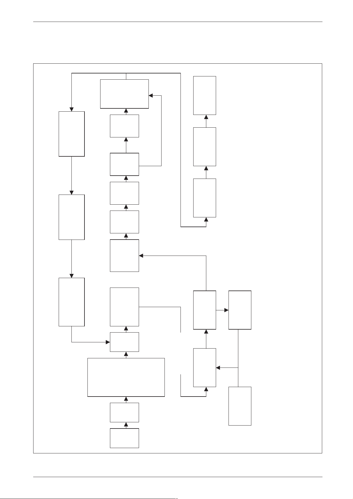
9.5 Operational Flow diagrams
9.5.1 Central heating function
Boiler
match
control
setting.
and CH
operates to
system load
*
Minimum
heat input
for 15min.
above set value.
Over temperature
shut-down if water
temperature is 5°C
Yes
long
Boiler
period.*
unused for
No
Appendix
3 mins.
run for upto
Pump and Fan
OFF.
closes.
Red light
Gas valve
6 720 610 576 - 25.1O
90 secs.
Fan min.
speed for
secs.
reduces
over 15
Gas valve shuts.
Pump remains ON.
Fan speed
satisfied.
CH demand
periods. (More than 24 hours without a demand).
OFF
Burner
start speed
stabilises at
for 5-10 secs
ce
* NOTE: The sequence ensures that the condensate siphon is not empty
after long
Yes
No
Fan to
Pump ON
programmer or
link ON
AND
CH
start speed.
Gas valve opens.
demand.
Ignition sequence
ON.
AND
(if fitted) ON
programmer
Electronic facia
CH control knob
Burner lights.
Red light ON.
5 seconds.
Ignition spark for
gas from burner.
Fan runs to purge
is below set value.
Burner remains OFF
until flow temperature
and/or mains
Room thermostat
Fig. 67
6 720 610 601 GB (03.02)
ON.
light
Green
ON.
Mains
switch
before lock-out.
Repeats 5 times
43
Page 44

AppendixAppendix
EXCELLENCE COMES AS STANDARD
Manufactured exclusively for British Gas by The Bosch Group
Bosch Group, Worcester Heat Systems, Cotswold Way, Warndon, Worcester WR4 9SW.
Telephone: (01905) 754624 Fax: (01905) 754619
Page 45
Service booklet for the Engineer
for Gas Condensing Boilers
6 720 610 577-00.10
ZWB 7-29 CC1
ZB 7-28 CS1
ZWB 7-27 HE combi
ZWB 7-25 HE combi
ZWB 7-30 HE combi
ZB 7-27 HE system
ZB 7-28 HE system
GC-Number: 47 108 05
GC-Number: 41 108 02
GC-Number: 47 311 55
GC-Number: 47 311 73
GC-Number: 47 311 74
GC-Number: 41 311 49
GC-Number: 41 311 58
Greenstar 29 HE Conventional
GC-Number: Natural Gas: 41 311 56; LPG: 41 311 57
7 181 465 346 GB (03.02) OSW
Page 46

Table of contents
Table of contents
Warnings 3
Symbols 3
1 Layout of Appliance 4
1.1 combi 4
1.2 system 5
2 Bosch Heatronic board functions 6
2.1 Initialisation 6
2.2 Temperature display 6
2.3 Indication of faults 6
2.4 Special programme visualisation 6
2.5 Boiler service functions 8
2.5.1 First Service Level 8
2.5.2 Secondary Service Level 11
3 Failure identification procedure 13
3.1 Notes on using the fault code tables 13
3.2 Summary 14
3.2.1 Appliance faults 14
3.2.2 Faults that are not displayed 14
3.3 Error codes on the display 15
3.4 Faults that are not displayed 42
3.4.1 Appliance faults 42
3.4.2 Programmer faults 48
4 Appendix 52
4.1 NTC values 52
4.1.1 Outside temperature sensor 52
4.1.2 CH flow NTC sensor, heat store
NTC sensor, constant hot water
NTC sensor and hot water NTC sensor 52
4.2 Electronic schemes 53
4.3 List of most important replacement parts 54
4.4 Approved corrosion inhibitors and
anti-freeze fluids for central
heating water 55
4.4.1 Frost protection 55
4.4.2 Sealing agents 55
4.5 Summary of BDH Information Sheet
on Identifying Corrosion by CFCs 55
2
7 181 465 346 GB (03.02)
Page 47

Warnings
Warnings
Repairs
B
Repairs may only be carried out by an approved
installer!
B
Before carrying out any work on the appliance,
switch it off at the master switch!
B
Even when the appliance is switched off at the master switch, some components on the PCB control
board inside the control box are still live. Therefore:
B
Before carrying out any work on the electrical parts
of the appliance fully disconnect it from the power
supply (e. g. by means of fuse or circuit breaker)!
B
Flue ducting must not be modified in any way.
B
Use only original spare parts!
Instructions to the customer
B
Explain to the customer how the appliance works
and how to operate it.
B
Advise the customer that he/she must not make any
modifications to the appliance or carry out any
repairs on it.
Symbols
Safety instructions
are identified by a warning-triangle symbol and are printed on a grey background.
Signal words indicate the seriousness of the hazard in
terms of the consequences of not following the safety
instructions.
•
Caution
could result.
•
Warning
ous damage to property could result.
•
Danger
result. In particularly serious cases, lives could be at
risk.
i
Notes contain important information in cases where
there is no risk of personal injury or damage to property.
indicates that minor damage to property
indicates that minor personal injury or seri-
indicates that serious personal injury could
Notes
are identified by the symbol shown
on the left. They are bordered by horizontal
lines above and below the text.
in this document
7 181 465 346 GB (03.02)
3
Page 48
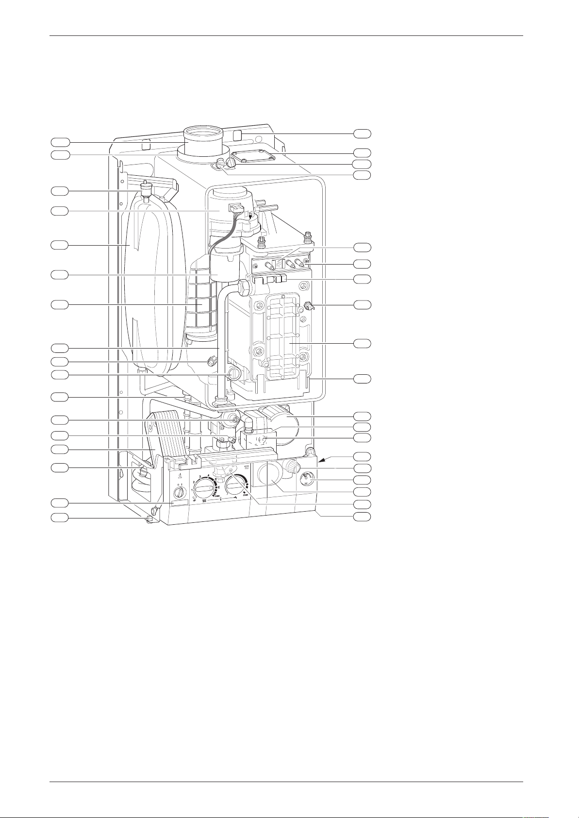
Layout of Appliance
1 Layout of Appliance
1.1 combi
221.1
221.2
27
226
20
29
271
43
9
63
358
120
349
234.1
234
102
32.1
36
6
415
416
64
7
355
6.1
295
417
Fig. 1
4
Heatronic control
6
Heat exchanger safety temperature limiter
6.1
Hot water NTC sensor
7
Testing point for gas supply pressure
8.1
Pressure gauge
9
Flue gas temperature limiter
15
Relief valve
18
Pump
18.1
Pump speed selector switch
20
Expansion vessel
27
Automatic air vent
29
Air gas Mixer unit
32.1
Electrode assembly
36
Temperature sensor in CH flow
43
CH flow
63
Adjustable gas flow restrictor
64
Adjusting screw for min. gas flow volume
88
3-way valve (combi)
98
DHW flow switch (combi)
102
Inspection window
6 720 610 576-02.2O
120
221.1
221.2
226
295
234
234.1
271
349
355
358
415
416
417
418
423
18
423
18.1
418
15
8.1
88
98
4
Fixing points
Flue duct
Combustion air intake
Fan assembly
Appliance type sticker
Testing point for combustion products
Testing point for combustion air
Flue duct
Cover plate for twin flue duct connection
Plate-type domestic hot water heat exchanger
Condensate trap
Cover plate for cleaning access
Condensate collector
Clip for fixing outer case
Data plate
Siphon
4
7 181 465 346 GB (03.02)
Page 49
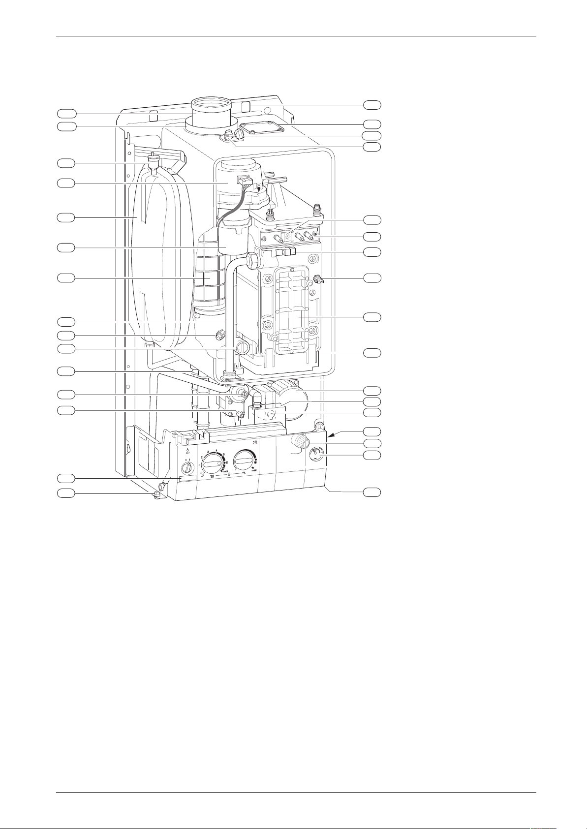
1.2 system
Layout of Appliance
221.1
221.2
27
226
20
29
271
43
9
63
358
120
349
234.1
234
102
32.1
36
6
415
416
64
7
295
417
Fig. 2
4
Heatronic control
6
Heat exchanger safety temperature limiter
7
Testing point for gas supply pressure
8.1
Pressure gauge
9
Flue gas temperature limiter
15
Relief valve
18
Pump
18.1
Pump speed selector switch
20
Expansion vessel
27
Automatic air vent
29
Air gas Mixer unit
32.1
Electrode assembly
36
Temperature sensor in CH flow
43
CH flow
63
Adjustable gas flow restrictor
64
Adjusting screw for min. gas flow volume
102
Inspection window
120
Fixing points
221.1
Flue duct
221.2
Combustion air intake
226
Fan assembly
295
Appliance type sticker
234
Testing point for combustion products
6 720 610 596-01.2O
234.1
271
349
358
415
416
417
418
423
18
423
18.1
418
15
8.1
4
Testing point for combustion air
Flue duct
Cover plate for twin flue duct connection
Condensate trap
Cover plate for cleaning access
Condensate collector
Clip for fixing outer case
Data plate
Siphon
7 181 465 346 GB (03.02)
5
Page 50

Bosch Heatronic board functions
2 Bosch Heatronic board func-
tions
2.1 Initialisation
When it is switched on, the appliance performs a selftest which takes about 5 seconds. While the test is in
progress, the display shows the following sequence of
codes:
P1
-> P2 -> P3 -> P4 -> P5 ->
On completion of the test sequence the appliance is
ready for operation.
2.2 Temperature display
The display shows the current flow temperature in central heating and hot water modes. The display range
extends from 00 ˚C to 99 ˚C.
If a service function requires the display of a temperature greater than 99 ˚C, the display alternates between
initially showing the first digit and then the remaining
two digits.
E.g.
: display showing 1. followed by
169˚C
.
For outside temperatures, the display shows a minus
sign followed by the negative temperature in alternation.
2.3 Indication of faults
Faults are indicated by a letter code. This helps to identify and eliminate the cause of the fault quickly and reliably.
The fault codes displayed are grouped into four categories:
•
Category 1:
The appliance is disabled until it has been switched
off and then on again.
•
Category 2:
The appliance is disabled until the cause of the fault
has been eliminated.
•
Category 3:
The appliance continues to operate with limited function.
•
Category 4:
The appliance is disabled and locked ( flashes)
until the cause of the fault has been eliminated and
the appliance unlocked.
i
Unlocking the appliance:
B
Press and hold the button until the
display shows
– –
P6
69.
indicates
.
2.4 Special programme visualisation
The display shows for example 45
ous working at the minimum sanitary/heating
power)
The display shows alternatively the temperature
and
. The function is memorised in the Service mode.
– –
• The appliance works continuously at the sanitary or
heating minimum power.
B
Press the button until the symbol
the display.
The button is lighted.
B
Turn the temperature control until function
appears on the display.
After a short delay, the display shows 1 for minimum
output.
B
Turn the temperature control completely anticlockwise until the display shows 0 .
B
Press the button until the symbol
the display.
The display shows the heating outlet temperature.
The display shows for example 55
(continuous working at the maximum power)
The display shows alternatively the temperature and
The function is memorised in the Service mode.
• The appliance works continuously at the maximum
power.
B
Press the button until the symbol
the display.
The button is lighted.
B
Turn the temperature control until function
appears on the display.
After about 5 seconds the display will show 2 for the
maximum power.
B
Turn the temperature control completely anticlockwise until the display shows 0 .
B
Press the button until the symbol
the display.
The display shows the heating outlet temperature.
Display shows 45 -II- 45 (trap filling programme)
The trap filling programme ensures that the condensation trap is filled after the appliance is first installed or if
it has been switched off for a long period.
The trap filling programme is activated if:
• the appliance is switched on at the master switch
• the burner has not been in operation for at least 48
hours
• the appliance is switched from summer to winter
mode.
45 (continu-
– –
appears on
– –
[ ]
appears on
– –
55
– –
appears on
[ ]
appears on
2.0
2.0
– –
.
6
7 181 465 346 GB (03.02)
Page 51
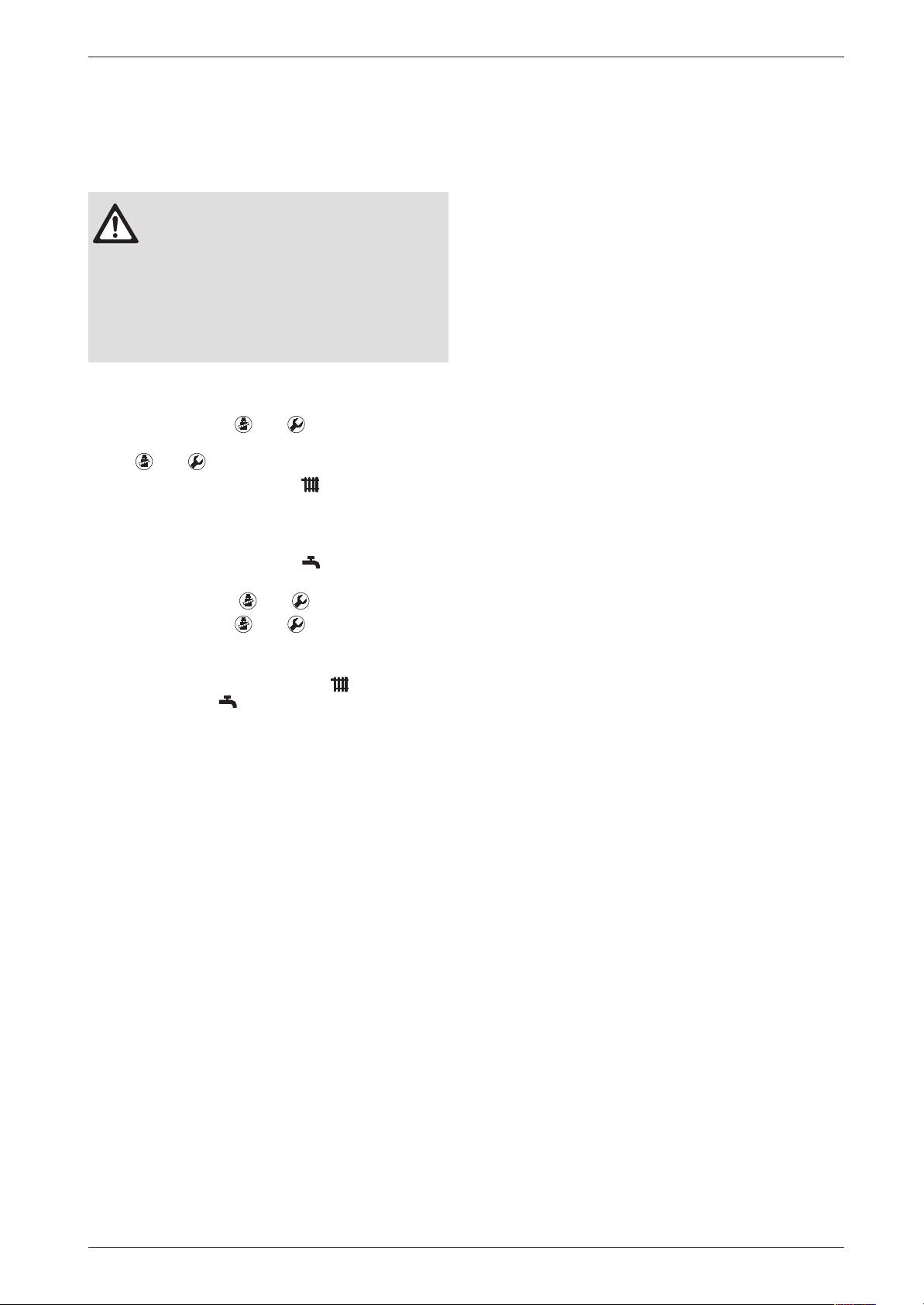
The next time the central heating or heat store calls for
heat, the appliance is held at a low heat output for 15
minutes. The display shows
-II-
in alternation with the
CH flow temperature.The factory setting is 1 (enabled).
If the condensation trap is not filled with
water, flue gas can escape!
B The trap filling programme should only
be disabled in order to carry out servicing work.
B Always re-enable the trap filling pro-
gramme after completing servicing
work.
To switch off the trap filling programme to carry out
servicing work:
B
Press and hold the and buttons simultaneously until the display shows
= =
.
The and buttons will light up.
B
Turn the temperature control until the display
shows
8.5
.
After a short delay, the display then shows the trap
filling programme setting (1. = Enabled).
B
Turn the temperature control until the display
shows 0. (= Disabled).
The display and the and buttons will flash.
B Press and hold the and buttons simultane-
ously until the display shows [ ].
The trap filling programme is now disabled.
B Regulate the temperature control and the tem-
perature control on the previously set positions.
The display shows the heating outlet temperature.
Display shows
0
(venting function)
0
The first time the appliance is switched on, it automatically activates a one-off venting sequence in which the
heating pump switches on and off at intervals for about
8 minutes.
This function can be activated on Service Level 2, Service Code 7.3, if it is required at any other time.
Bosch Heatronic board functions
7 181 465 346 GB (03.02)
7
Page 52
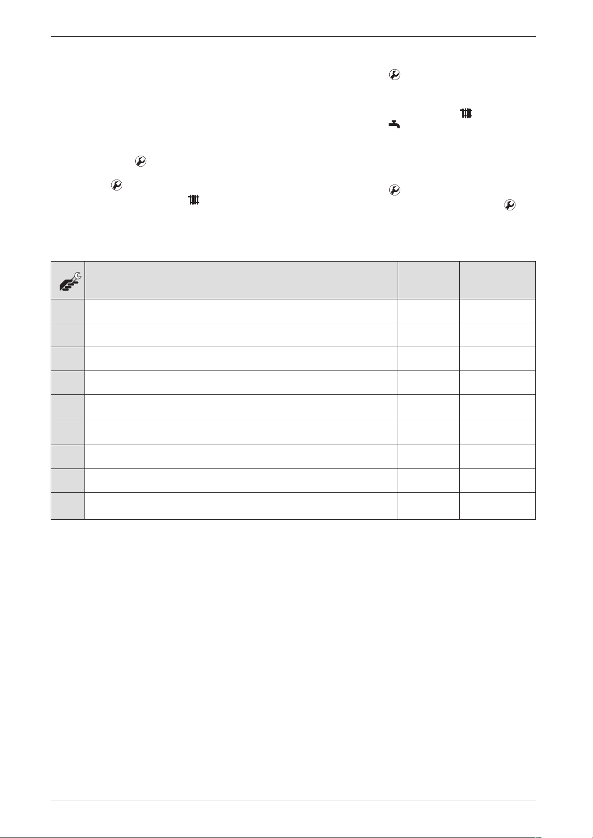
Bosch Heatronic board functions
2.5 Boiler service functions
B Press the button until the symbol [ ] appears on
the display.
2.5.1 First Service Level
Operating
The display shows the heating outlet temperature.
B Regulate the temperature control and the tem-
perature control on the previously set positions.
In order to change or check the values of the service
functions:
B Press the button until the symbol
– –
appears on
the display.
The button is lighted.
B Turn the temperature control until the desired
function number appears on the display.
Once changed or checked the function value:
In order to reset the main menu function values to their
default values:
B Power OFF the appliance.
B Press the button and keep it pressed.
B Switch on the appliance, press and hold the but-
ton until the
display shows r1 followed by [ ].
Values that can be modified:
Description Display Reset Value
.0 Show the last error code. 0 - FF Clear only
2.0 Identification of the function mode (0 = normal, 1= min, 2 = max) 0 - 2 0
2.2 Identification of the pump function mode 1 - 3 2
2.3 Max. output in heat store heating mode 28 - 99 99
2.4
Anti-cycle time
1)
0 - 15 min 3 min
2.5 Max. CH flow temperature 35 - 88˚C 88˚C
2.6 Minimum hysteresis in heating mode (∆T) 0 - 30 K 0 K
2.7 Activation of automatic anti-cycle time (0 = Disabled; 1 = Enabled) 0, 1 1
3.4 Pump mode 0 - 3
2)
Table 1 First Service Level; Values that can be modified
1) If appliance is used in conjunction with type TA... programmer, only effective if Service Code 2.7 is set to “0” (= "Disabled”)!
2) The reset value is dependent on the code plug.
8
7 181 465 346 GB (03.02)
Page 53
Bosch Heatronic board functions
Values that can only be read:
Description Display Reset Value
.1 Heating outlet temperature. 0 - 99˚C -
.2 Sanitary outlet temperature. 0 - 99˚C -
.3 Heat store NTC sensor (ZSB.) 0 - 99˚C
.4 Constant hot water NTC sensor (ZWB.) 0 - 99˚C -
1.2 Order no. for code plug: 8 714 411 XXX 0 - 255 -
1.4 Temperature voltage signal (Terminal 2) from room thermostat
5 - 22 VDC -
(eg. TRQ 21, TR 100)
1.5 Specified CH flow temperature from programmer 0 - 99˚C -
1.6 Outside temperature from TA 211 E or room temperature from
-20 +30˚C -
TR 212 E
1.7 Status TR 2 (0 = Not present 1 = Frost protection 3 = Auto 4 = Day,
0 - 4 -
Night 5=Error)
1.8 Terminal 2 on programmer interface module 0 - 24 VDC -
1.9 Identification code for the external module:
0, 2, 4, 5 = no module connected,
0 - 8, 53,
56
3 = ADM, 6 = TA 211E, 53 = ADM, 56 = TR 212 E).
2.9 Instantaneous power. 0 - 99 % -
3.0 Fan speed 0 - 105 -
3.3 Quality of the ionisation signal:
0 - 3 0 = no ionisation,
1 = weak ionisation,
2 = medium ionisation,
3 = high ionisation.
-
3.6 Software version 3 x 2
positions
Table 2 First Service Level; Values that can only be read
7 181 465 346 GB (03.02)
-
9
Page 54
Bosch Heatronic board functions
Values that can only be read - only left display digit:
Description Display XY Reset Value
3.9 External switch (points 8 - 9). 0 = closed
1 = Heating demand
4.1 External demand for heat via LSM 0 = closed
1 = Heating demand
4.2 Programmable clock:
1st channel (Heating).
4.3 Automatic pump shut OFF with RAM module
(point 5)
0 = closed
1 = Heating demand
0 = closed
1 = Heating demand
4.4 Heating demand. 0 = closed
1 = Heating demand
4.5 Sanitary demand. 0 = closed
1 = Heating demand
Table 3 First Service Level; Values that can only be read - only left display digit
Values that can only be read - only right display digit:
Description Display XY Reset Value
-
-
-
-
-
-
3.9 External 2-point demand for heat via 230 V AC
(Terminals Ls - Lr)
4.0 Heat store demand for heat via
heat store thermostat (Terminals 7-9)
0 = closed
1 = Heating demand
0 = closed
1 = Heating demand
4.1 LSM Enable 0 = closed
1 = Heating demand
4.2 Programmable clock:
2nd channel (DHW – Maintaining).
0 = closed
1 = Heating demand
4.3 Heating demand from TA 211 E 0 = closed
1 = Heating demand
4.4 Heat store demand for heat via heat store NTC
sensor
0 = closed
1 = Heating demand
4.5 Sanitary heat exchanger temperature maintaining. 0 = closed
1 = Heating demand
4.6 Anti-cycle time 0 = closed
1 = Heating demand
Table 4 First Service Level; Values that can only be read - only right display digit
-
-
-
-
-
-
-
-
10
7 181 465 346 GB (03.02)
Page 55
Bosch Heatronic board functions
2.5.2 Secondary Service Level
B Press buttons and simultaneously until the
symbol [ ] appears on the display.
Operation
In order to change or check the values of the service
functions:
B Press buttons and simultaneously until the
symbol = = appears on the display.
The buttons and are lighted.
B Turn the temperature control until the desired
function number appears on the display.
The display shows the heating outlet temperature.
B Regulate the temperature control and the tem-
perature control on the previously set positions.
To reset all settings on Service Levels 1 and 2 to the
factory setting:
B Power OFF the appliance.
B Press buttons and simultaneously and keep
them pressed.
Once changed or checked the function value:
B Switch on appliance, press and hold the and
buttons until the display shows r2 followed by [ ].
Values that can be modified:
Description Display Reset Value
5.0 Reduced max. heating output 0 - 99 % and sealed 99
5.1 Continuous ignition (for testing ignition without
gas)
0 = off
1 = on
0
5.5 Increased min. heating and heat store charging
0 - 99 % 0
output
5.9 Starting speed option (if flame propagation is
poor, set high starting speed)
0 = First start at low speed;
1 = First start at high speed)
6.7 Pump deactivation in HW mode, ZW only. 0 = off, 1 = on 1
6.8 Cycle time for heat exchanger constant hot water
0 - 60 min 0
function on ZW model.
6.9 Constant hot water 0 - 30 min 3
7.3 Venting function 0 = off,
1 = On for 8 cycles then
permanently off (i.e. set to 0)
2 = on
7.7 Temperature-dependent output reduction 0 = off;
1 = Heating on
2 = Hot water on
3 = Heating and hot water on
8.5 Trap filling programme 0 = off
1 = on
0
1
3
1
Table 5 Secondary Service Level; Values that can be modified
7 181 465 346 GB (03.02)
11
Page 56
Bosch Heatronic board functions
Values that can only be read:
Description Display Reset Value
5.2 Automatic gas igniter status and/or fault 00 - FF -
9.3 Automatic gas igniter Asic fault code 00 - FF -
Table 6 Secondary Service Level; Values that can only be read
12
7 181 465 346 GB (03.02)
Page 57
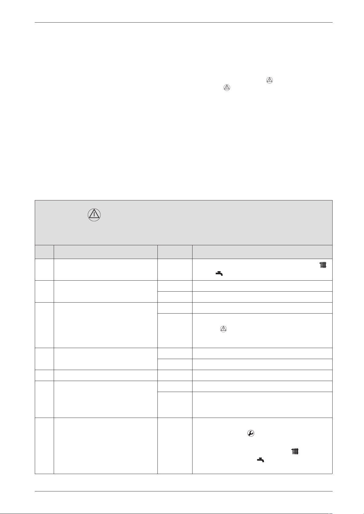
3 Failure identification procedure
Failure identification procedure
3.1 Notes on using the fault code
tables
The procedure is best described with the aid of
an example:
• Work through the table from top to bottom and from
left to right.
• First make a note of the present settings and restore
them before leaving the appliance.
• Read question 1. (Check column)and depending on
the answer (yes or no) read the action required from
the relevant box and carry out the instruction given;
ignore the other answer. For example: if the burner
flame is visible, follow the instructions for yes, i.e.
↓5.!
• ↓5. means go to number 5., ignoring the steps in
between.
EA and flashing.
Flame not detected
In this example: check the flue is clear by testing
the CO2 level.
• If the appliance is locked ( button is flashing),
press the button. Important: after unlocking the
appliance, always restart it (i.e. switch off and then
on again). Only then is it possible to say whether or
not the fault has been eliminated.
• If the fault has been rectified, the appliance will then
start up without indicating a fault and the fault isolation procedure is complete.
• If the fault is still present after performing the action
specified and, if necessary, restarting the appliance,
move on to the next step in the fault isolation procedure.
• If another fault code is displayed, work through the
fault code table for that code.
Check Action
B Note the setting of the temperature controls
1. Is a burner flame visible? yes: ↓ 5.
no: ↓ 2.
2. Is the gas cock turned on? yes: ↓ 5.
no: B Open the gas cock.
B Press , restart the appliance.
EA? ↓3.
3. Has the thermal cut-out on the gas
cock tripped?
4. ... ...
5. ... Problem with flue?
B Check CO2 level in combustion
air.
Is CO2 level above 0,2 % ?
yes: ...
no: ↓ ...
yes: Check flue.
no: ↓ ...
Return to normal operation:
and .
Table 7
7 181 465 346 GB (03.02)
B Press the button until the symbol [ ] appears
on the display.
B Regulate the temperature control and the
temperature control on the previously set
positions.
13
Page 58
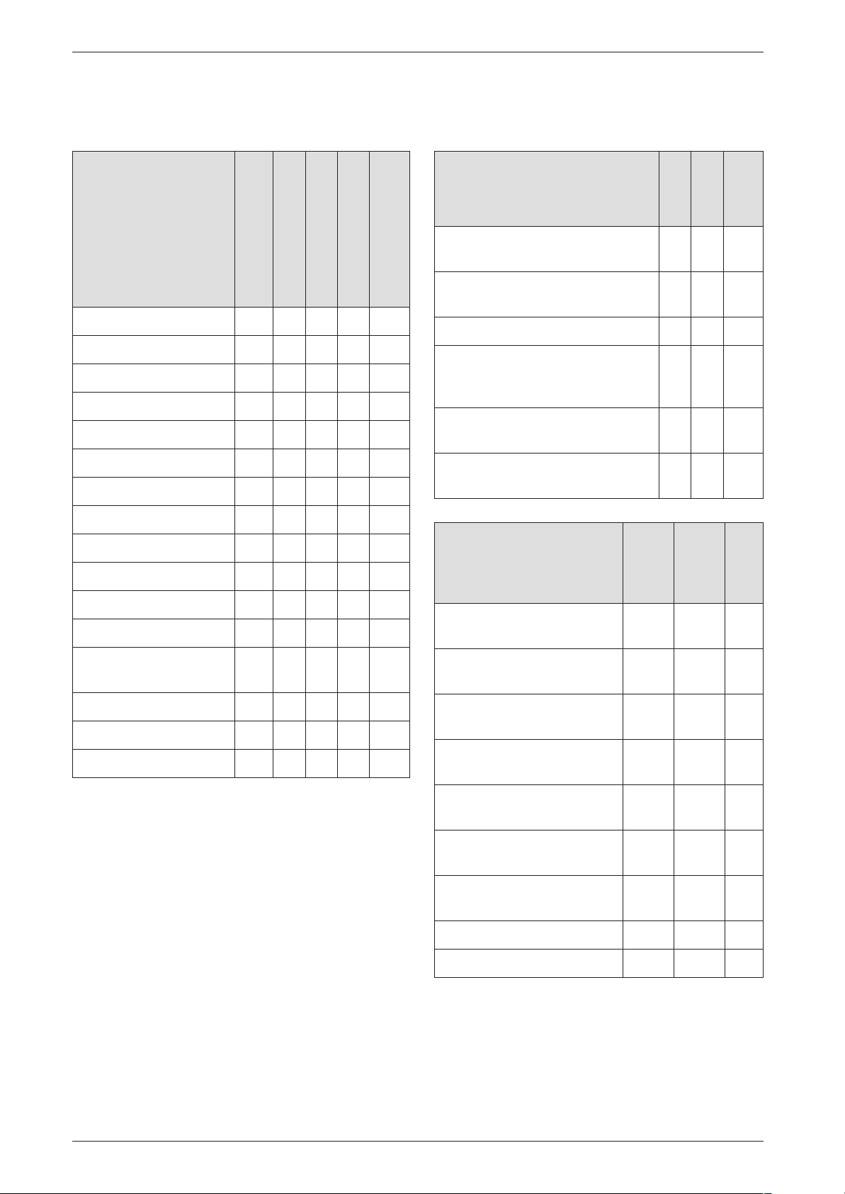
Failure identification procedure
3.2 Summary
3.2.1 Appliance faults 3.2.2 Faults that are not displayed
Appliance faults
A5 3 X 15
A7 3 X 17
A8 3 X X X 19
AC 3 X X X 20
Ad 3 X 22
b1 2 X X X 24
C1 2 X X X 25
CC 3 X X X 26
d3 2 X X X 27
E2 2 X X X 28
E9 4 X X X 30
EA 4 X X X 32
Category
ZB ...A
ZB ...A Conventional
ZWB ...A
Page
Appliance faults
Excessive burner noise, rumbling
noises
Flue gas levels incorrect, CO level
too high
Ignition too harsh, ignition poor. X X 44
Boiler indicates P1, P2, P3 at
start-up and then restarts
with P1,...
Loose or broken contact on heat
store NTC sensor
Specified CH flow temperature
from TA... programmer exceeded
Table 9
Programmer faults
Set room temperature not
reached.
X 48
ZB ...A
X X 42
X X 43
X X 46
X X 46
X X 47
TR 2 and
TR 212 E
ZWB ...A
TA 211E
and DT 2
Page
Page
F0 4/2XXX 37
F7 4 X X X 38
FA 4 X X X 39
Fd 4 X X X 41
Table 8
Set room temperature
exceeded.
Set room temperature not
reached.
Set room temperature
exceeded by large amount.
Excessive fluctuations in
room temperature
Temperature rises instead of
falling
Room temperature too high
in Economy mode
Incorrect or no modulation X X 51
Heat store fails to heat up X
Table 10
X
X 49
X 50
X X 50
X X 51
X X 50
14
7 181 465 346 GB (03.02)
Page 59
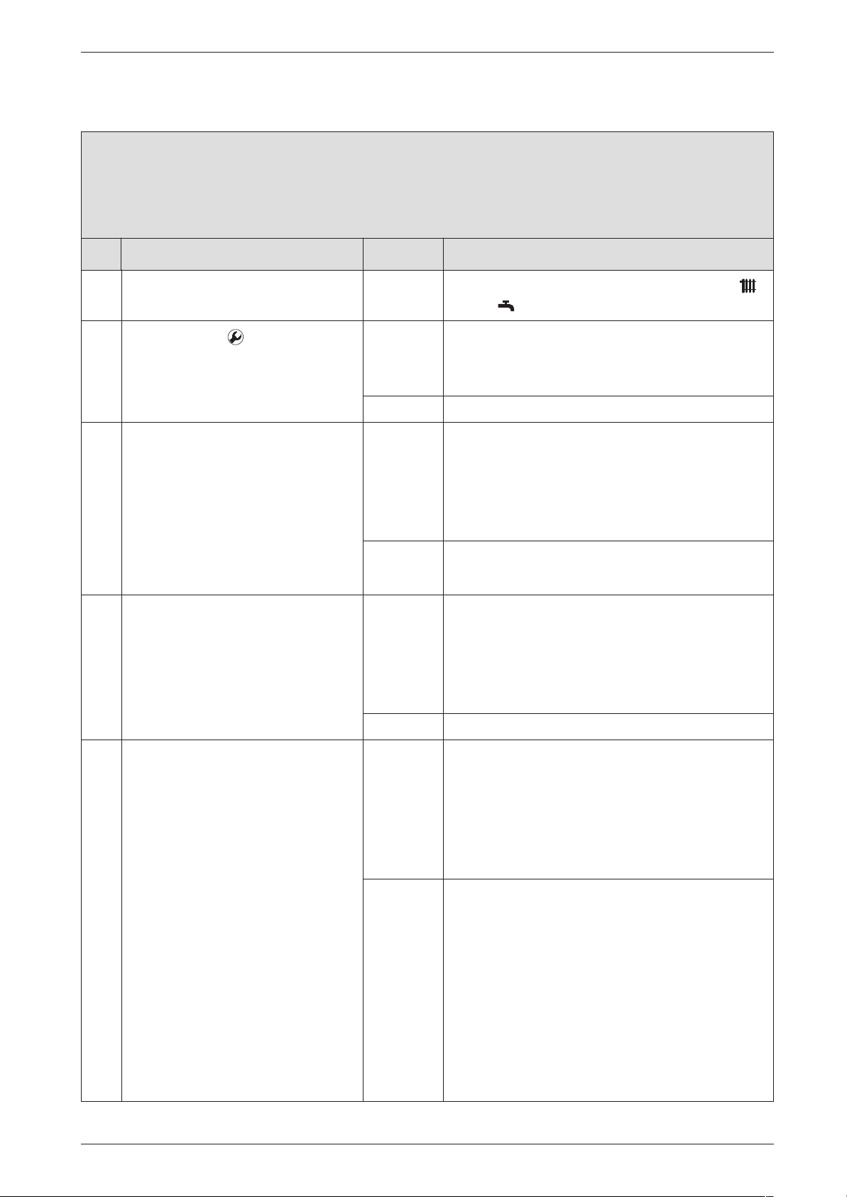
3.3 Error codes on the display
A5 flashing.
Heat store NTC sensor 2 defective
Check Action
1.
B Press button .
B Select service function .3 .
Is a temperature between 0. and
5. displayed?
B Note the setting of the temperature controls
yes:
no: ↓3.
B Flue gas connector corroded
↓2.
Failure identification procedure
and .
dirty?. Change relative parts.
1)
, damaged or
2. Heat store NTC:
B Unplug connector.
B Short circuit the connector.
Display changes to temperature
between 99. and 95.
3. Temperature between 95. and 99. is
displayed.
B Unplug connector.
After max. 60 sec.:
Does the displayed code change
to a value between 0. and 5.?
4. B Unplug 20-pin connector from
PCB.
After max. 60 sec.:
Does the displayed code change
to a value between 0. and 5.?
yes: B Power OFF the appliance.
B Change NTC sensor.
B Plug the connection wire.
B Turn ON the appliance.
A5? ↓3.
no: B Change the 20-pin connector lead assembly.
↓3.
yes: B Power OFF the appliance.
B Change NTC sensor.
B Plug the connection wire.
B Turn ON the appliance.
A5? ↓4.
no: ↓4.
yes: B Power OFF the appliance.
B Disconnect the boiler electrical connection.
B Change the 20-pin connector lead assembly.
B Reconnect the boiler electrical connection.
B Turn ON the appliance.
7 181 465 346 GB (03.02)
↓5.
no: B Make a note of the altered service settings (see
table 1, "First Service Level; Values that can be
modified" at page 8 and table 5, "Secondary
Service Level; Values that can be modified" at
page 11).
B Power OFF the appliance.
B Disconnect the boiler electrical connection.
B Change PCB control board.
B Reconnect the boiler electrical connection.
B Turn ON the appliance.
B Restore service settings previously noted down.
15
Page 60
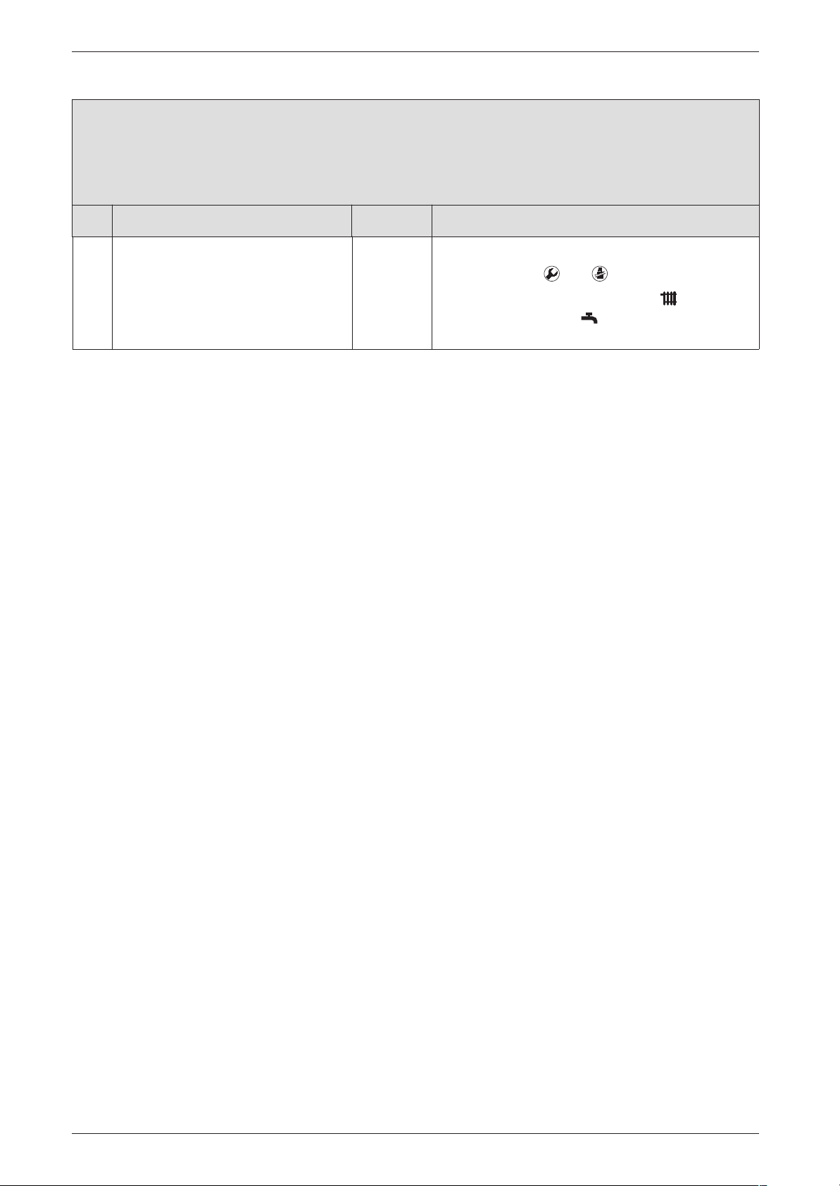
Failure identification procedure
A5 flashing.
Heat store NTC sensor 2 defective
Check Action
5. To return to normal function mode:
B Press buttons and simultaneously.
B Regulate the temperature control and the
temperature control on the previously set
positions.
1) For notes, refer to Appendix
16
7 181 465 346 GB (03.02)
Page 61
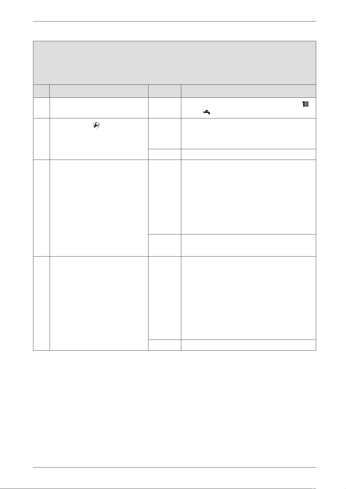
A7 flashing.
Hot water NTC sensor defective
Check Action
1.
B Press button .
B Select service function .2 .
Is a temperature between 0. and
5. displayed?
yes:
no: ↓3.
Failure identification procedure
B Note the setting of the temperature controls
and .
B Flue gas connector corroded
dirty? Change relative parts.
↓2.
1)
, damaged or
2. Hot water NTC sensor:
B Unplug connector.
B Short circuit the connector.
Display changes to
temperature 99.
3. Temperature between 95. and 99. is
displayed.
B Unplug connector.
After max. 60 sec.:
Does the displayed code change
to a value between 0. and 5.?
yes: B Power OFF the appliance.
B Drain the hot water circuit.
B Disconnect the boiler electrical connection.
B Change NTC sensor.
B Plug the connection wire.
B Reconnect the boiler electrical connection.
B Turn ON the appliance.
A7? ↓3.
no: B Change the 20-pin connector lead assembly.
↓3.
yes: B Power OFF the appliance.
B Disconnect the boiler electrical connection.
B Change NTC sensor.
B Refill the hot water circuit.
B Check the built-in NTC sensor for leaks.
B Plug the connection wire.
B Reconnect the boiler electrical connection.
B Turn ON the appliance.
7 181 465 346 GB (03.02)
A7? ↓4.
no: ↓4.
17
Page 62
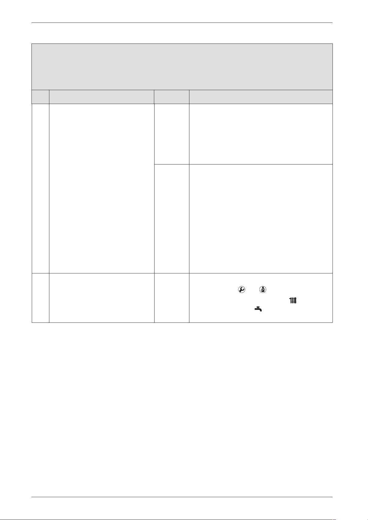
Failure identification procedure
A7 flashing.
Hot water NTC sensor defective
Check Action
4. B Unplug 20-pin connector from
PCB.
After max. 60 sec.:
Does the displayed code change
to a value between 0. and 5.?
5. To return to normal function mode:
yes: B Power OFF the appliance.
B Disconnect the boiler electrical connection.
B Change the 20-pin connector lead assembly.
B Reconnect the boiler electrical connection.
B Turn ON the appliance.
↓5.
no: B Make a note of the altered service settings (see
table 1, "First Service Level; Values that can be
modified" at page 8 and table 5, "Secondary
Service Level; Values that can be modified" at
page 11).
B Power OFF the appliance.
B Disconnect the boiler electrical connection.
B Change PCB control board.
B Reconnect the boiler electrical connection.
B Turn ON the appliance.
B Restore service settings previously noted down.
↓5.
1) For notes, refer to Appendix
B Press buttons and simultaneously.
B Regulate the temperature control and the
temperature control on the previously set
positions.
18
7 181 465 346 GB (03.02)
Page 63
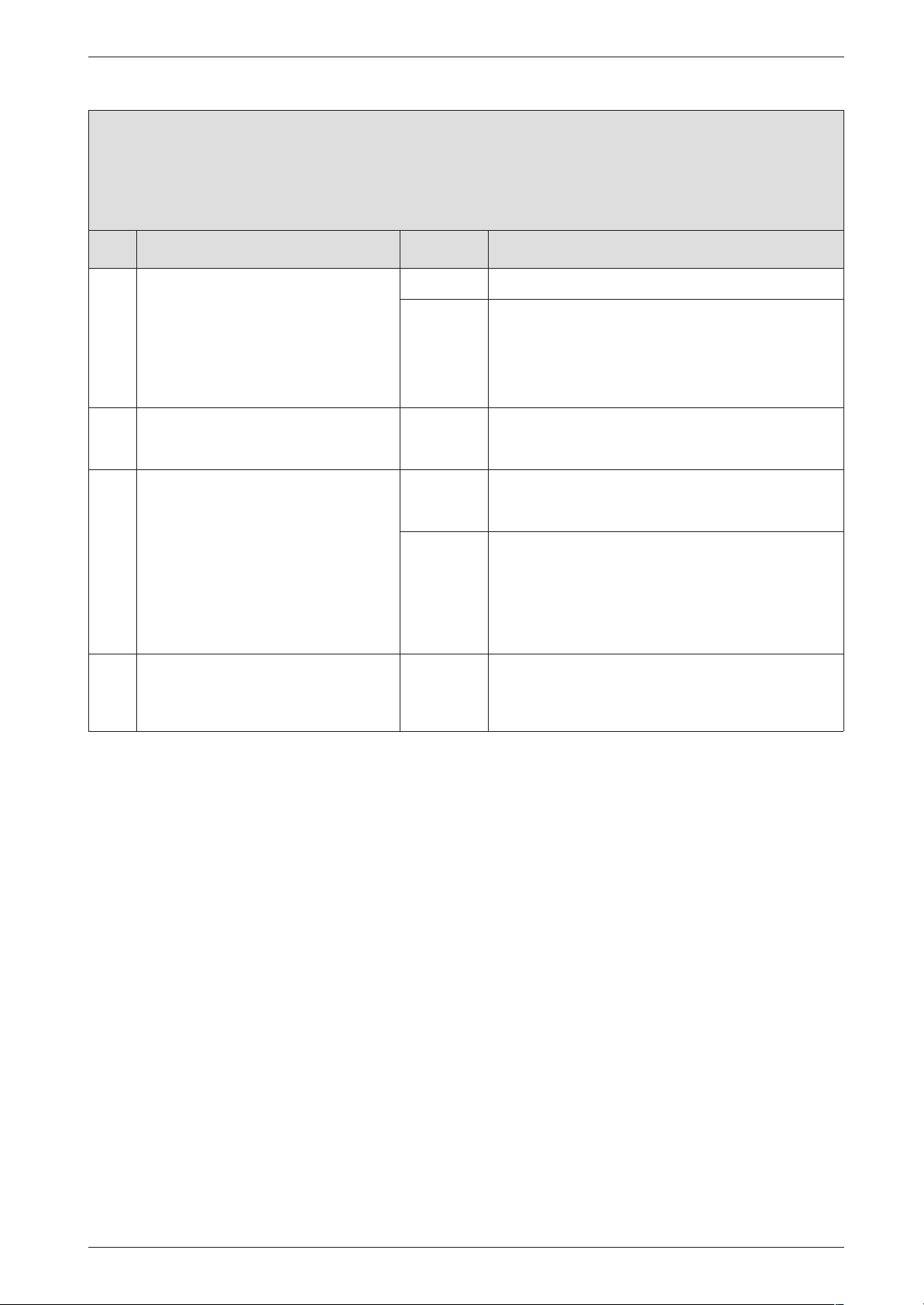
A8 flashing.
No correct electrical connection
Check Action
1. TR 2 connected? yes: A8? ↓2.
no: B Power OFF the appliance.
B Connect TR 2.
B Turn ON the appliance.
A8? ↓2.
Failure identification procedure
2. Mode selector switch is between two
settings
3. B Power OFF the appliance.
Wiring between TR 2 and TR 212 E
OK?
• Terminal 3 on TR 2 connected to
Terminal 3 on TR 212 E?
• Terminal 4... Terminal 4....
4. TR 2 defective B Power OFF the appliance.
yes: B Turn ON the appliance.
no: B Rewire correctly as specified in the installation
B Turn switch until it clicks into position.
A8? ↓3.
↓4.
instructions.
B Turn ON the appliance.
After 90 sec.:
A8? ↓4.
B Change TR 2.
B Turn ON the appliance.
7 181 465 346 GB (03.02)
19
Page 64
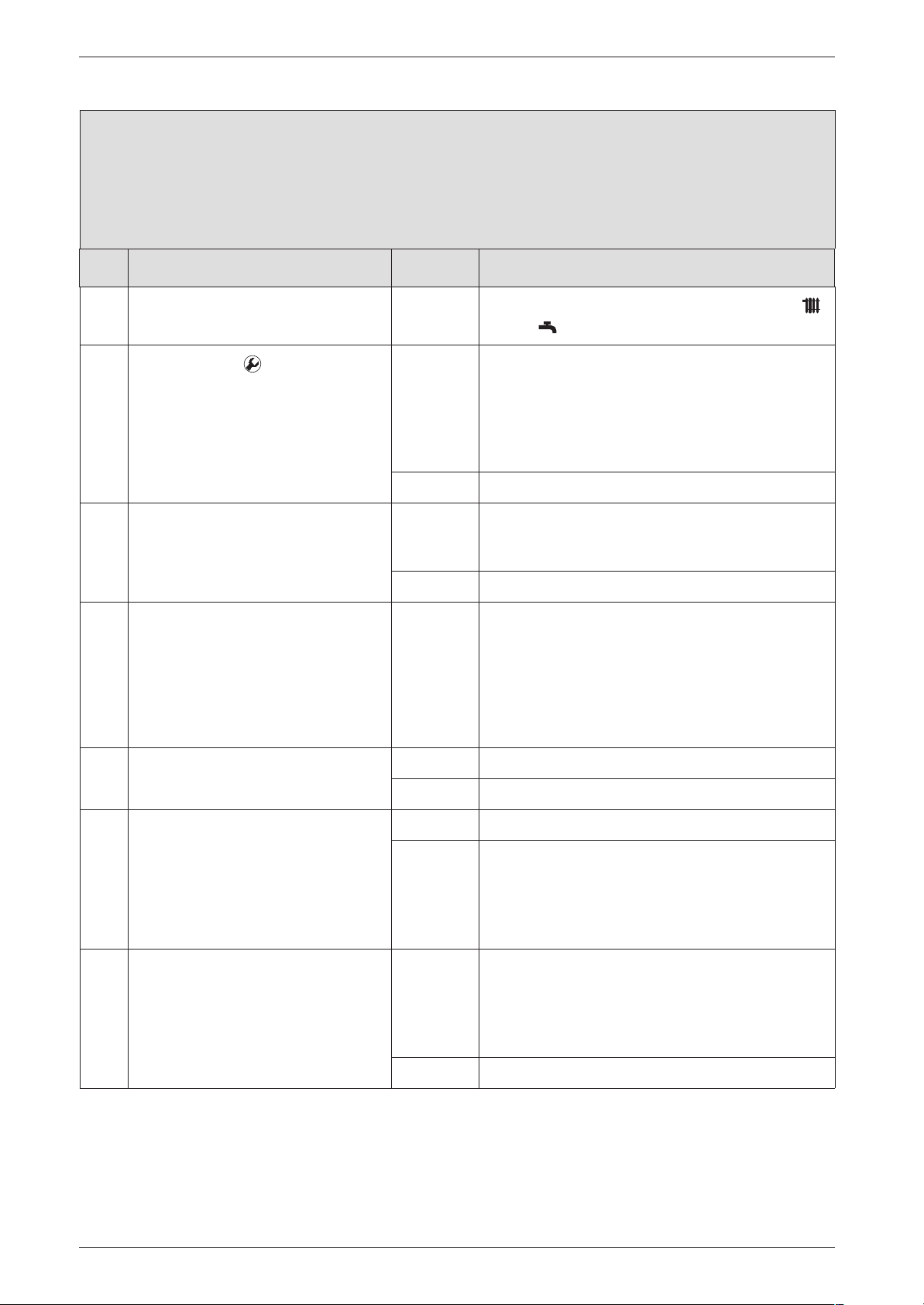
Failure identification procedure
AC flashing.
Module not detected.
(Constant CH flow temperature according to CH temperature control on boiler.)
Check Action
B Note the setting of the temperature controls
and .
1.
2. Are 24 V DC cables routed along-
3. Connecting lead between PCB con-
4. TA 211 E connected? yes: ↓5.
B Press button .
B Select service function 1.9 .
Code 0., 2., 4., 5. is displayed.
side 230 V AC cables?
trol board and TA 211 E or TA 212 E
defective.
yes: No modul detected.
B Disconnect connecting lead between PCB con-
B Re-connect connecting lead.
AC? ↓3.
no: ↓2.
yes: B Ensure cable separation conforms to minimum
no: ↓3.
B Power OFF the appliance.
B Replace connecting lead between PCB control
B Turn ON the appliance.
AC? ↓4.
no: ↓8.
trol board and TA 211 E or TA 212 E.
requirements as per installation instructions and/
or use shielded cable.
board and programmer interface module or TA
211 E.
5. B Select service function 1.6 .
Outside temperature between -20
and +30 ˚C is displayed.
Does temperature displayed
match true outside temperature?
6. If remote control installed:
B Select service function 1.7 .
Remote control status 0. is displayed .
20
yes: ↓7.
no: B Power OFF the appliance.
B Replace outside temperature sensor.
B Turn ON the appliance.
AC? ↓7.
yes: B Power OFF the appliance.
B Plug the connection wire.
B Turn ON the appliance.
AC? ↓7.
no: ↓7.
7 181 465 346 GB (03.02)
Page 65
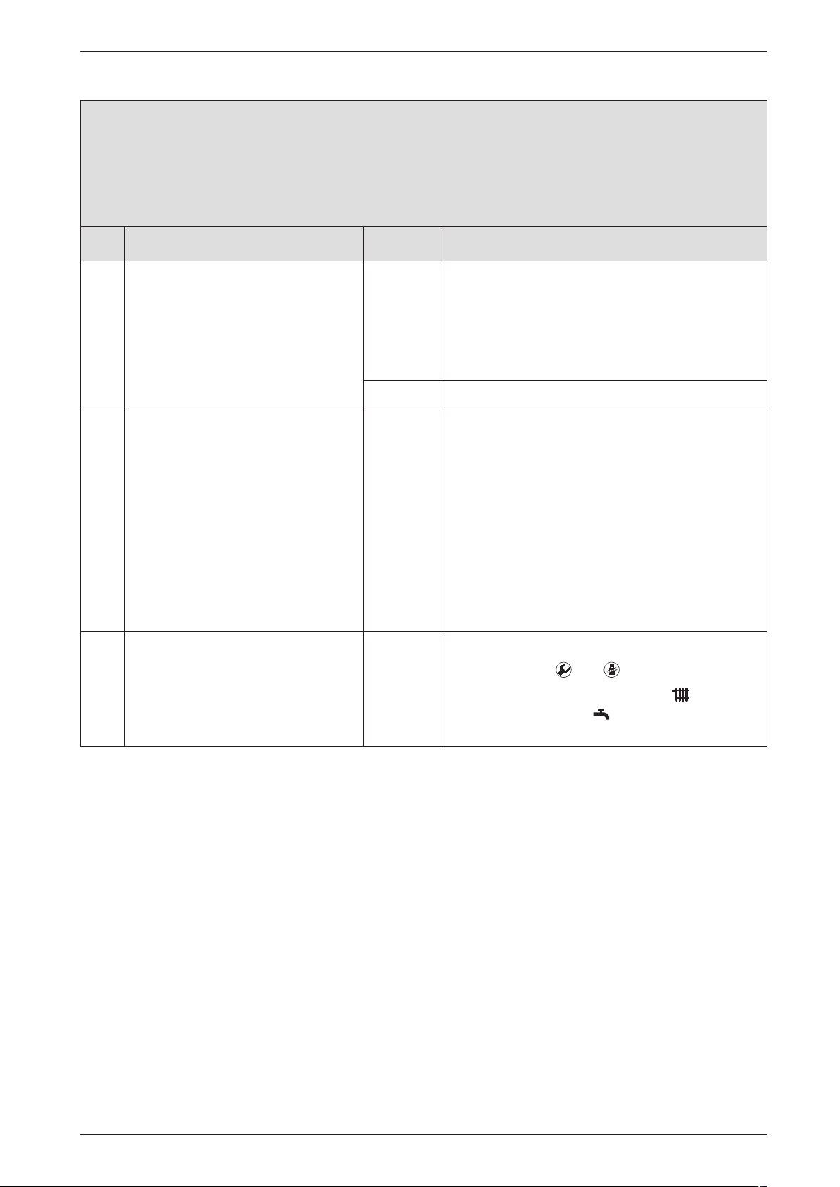
Failure identification procedure
AC flashing.
Module not detected.
(Constant CH flow temperature according to CH temperature control on boiler.)
Check Action
7. Remote control status still 0.? yes: B Power OFF the appliance.
Remote control:
B Replace top section.
B Turn ON the appliance.
AC? ↓8.
no: ↓8.
8. The PCB control board is damaged. B Make a note of the altered service settings (see
table 1, "First Service Level; Values that can be
modified" at page 8 and table 5, "Secondary
Service Level; Values that can be modified" at
page 11).
B Power OFF the appliance.
B Disconnect the boiler electrical connection.
B Change PCB control board.
B Reconnect the boiler electrical connection.
B Turn ON the appliance.
B Restore service settings previously noted down.
To return to normal function mode:
B Press buttons and simultaneously.
B Regulate the temperature control and the
temperature control on the previously set
positions.
7 181 465 346 GB (03.02)
21
Page 66

Failure identification procedure
Ad flashing.
Heat store NTC sensor 1 not detected (ZB...).
Check Action
B Note the setting of the temperature controls
and .
1. Is connecting lead for heat store
NTC sensor 1 correctly routed, i.e.
not through cable grommet?
2.
3. Heat store -NTC 1:
B Press button .
B Select service function .3 .
Is a temperature between 0. and
5. displayed?
B Unplug connector from PCB con-
trol board.
B Short circuit the connector using
wire jumper.
After max. 60 sec:
Display changes to temperature
between 99. and 95.
yes: ↓2.
no: B Route connecting lead for heat store tempera-
ture sensor as specified in installation instructions.
yes: Is NTC sensor connector corroded, damaged or
dirty?
B Power OFF the appliance.
B Change NTC sensor.
B Turn ON the appliance.
B Press button .
Ad? ↓3.
no: ↓4.
yes: B Power OFF the appliance.
B Change NTC sensor.
B Turn ON the appliance.
B Press button .
↓4.
no: B Make a note of the altered service settings (see
table 1, "First Service Level; Values that can be
modified" at page 8 and table 5, "Secondary
Service Level; Values that can be modified" at
page 11).
B Power OFF the appliance.
B Disconnect the boiler electrical connection.
B Change PCB control board.
B Reconnect the boiler electrical connection.
B Turn ON the appliance.
B Restore service settings previously noted down.
22
↓4.
7 181 465 346 GB (03.02)
Page 67
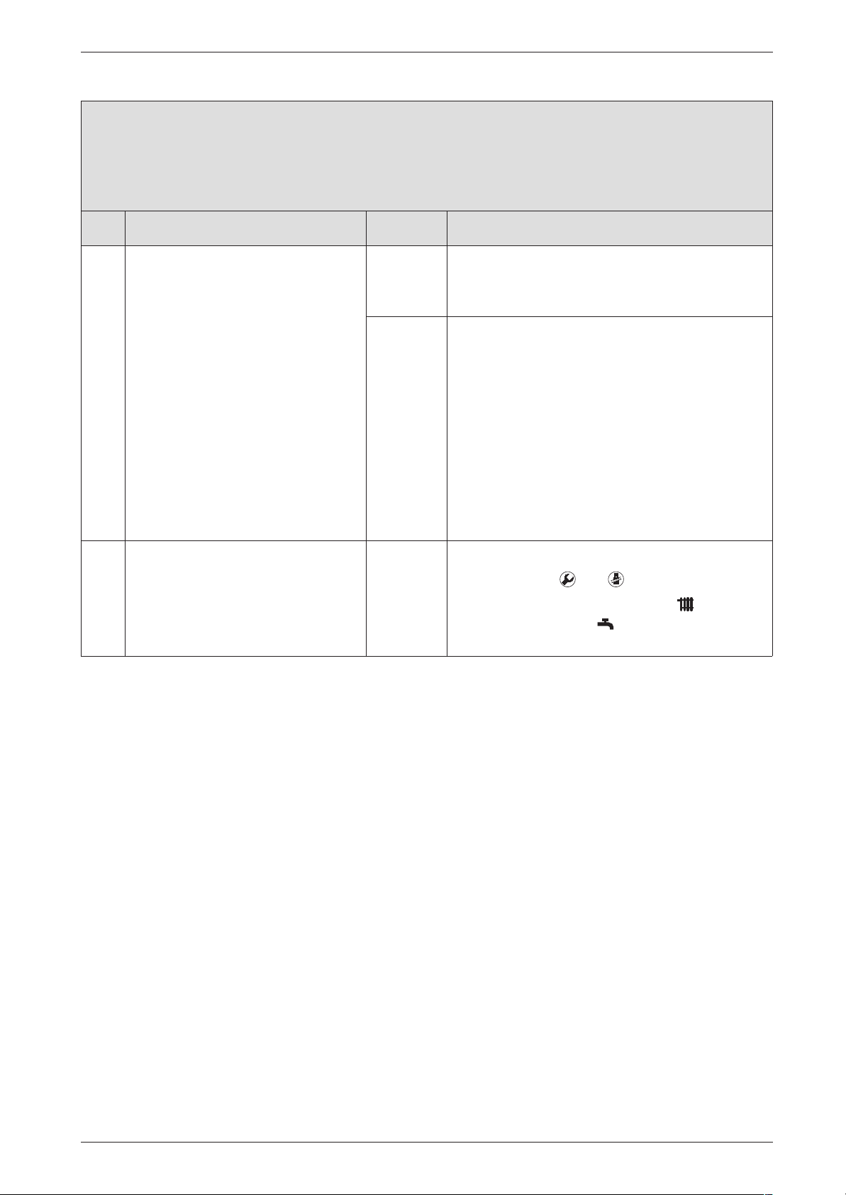
Ad flashing.
Heat store NTC sensor 1 not detected (ZB...).
Check Action
Failure identification procedure
4. Temperature between 99. and 95. is
displayed.
B Unplug connector.
After max. 60 sec.:
Does the displayed code change
to a value between 0. and 5.?
yes: B Power OFF the appliance.
B Change NTC sensor.
B Turn ON the appliance.
no: B Make a note of the altered service settings (see
table 1, "First Service Level; Values that can be
modified" at page 8 and table 5, "Secondary
Service Level; Values that can be modified" at
page 11).
B Power OFF the appliance.
B Disconnect the boiler electrical connection.
B Change PCB control board.
B Reconnect the boiler electrical connection.
B Turn ON the appliance.
B Restore service settings previously noted down.
To return to normal function mode:
B Press buttons and simultaneously.
B Regulate the temperature control and the
temperature control on the previously set
positions.
7 181 465 346 GB (03.02)
23
Page 68

Failure identification procedure
b1 flashing.
The Heatronic does not recognise the code key.
Check Action
1. B Power OFF the appliance.
2. Code plug loose, incorrect or defective.
3. The PCB control board is damaged. B Make a note of the altered service settings (see
B Replace code plug, check code number is cor-
rect.
B Turn ON the appliance.
b1? ↓3.
table 1, "First Service Level; Values that can be
modified" at page 8 and table 5, "Secondary
Service Level; Values that can be modified" at
page 11).
B Power OFF the appliance.
B Disconnect the boiler electrical connection.
B Change PCB control board.
B Reconnect the boiler electrical connection.
B Turn ON the appliance.
B Restore service settings previously noted down.
24
7 181 465 346 GB (03.02)
Page 69
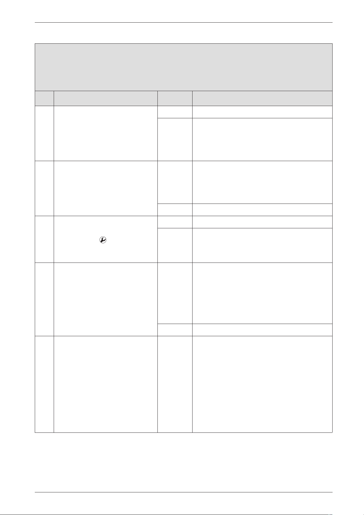
C1 flashing.
Fan speed too low
Check Action
Failure identification procedure
1. Fan lead connector properly connected?
2. Is fan lead defective?
B Is impedance reading between the
two connectors for one of the
cores infinity?
3. Are the differential pressure switch
contacts closed?
B Press button .
B Select service function 3.8 .
Is left digit of display showing 1?
4. Fan defective? yes: B Power OFF the appliance.
yes: ↓2.
no: B Power OFF the appliance.
B Plug in connector.
B Turn ON the appliance.
C1? ↓2.
yes: B Power OFF the appliance.
B Replace fan lead.
B Turn ON the appliance.
C1? ↓3.
no: ↓3.
yes: ↓4.
no: ↓4.
B Plug the connection wire.
B Replace fan.
B Plug the connection wire.
B Turn ON the appliance.
C1? ↓5.
no: ↓5.
5. The PCB control board is damaged. B Make a note of the altered service settings (see
table 1, "First Service Level; Values that can be
modified" at page 8 and table 5, "Secondary
Service Level; Values that can be modified" at
page 11).
B Power OFF the appliance.
B Disconnect the boiler electrical connection.
B Change PCB control board.
B Reconnect the boiler electrical connection.
B Turn ON the appliance.
B Restore service settings previously noted down.
7 181 465 346 GB (03.02)
25
Page 70
Failure identification procedure
CC flashing.
Outside temperature NTC sensor not detected.
(Boiler heating as if outside temperature is -20˚C)
Check Action
1. Outside temperature sensor AF2
connected to Terminals A and F on
TA 211 E?
2. B Power OFF the appliance.
B Disconnect outside temperature
sensor and test resistance
R = ∞ or R = 0?
yes: ↓2.
no: B Power OFF the appliance.
B Connect outside temperature sensor to Termi-
nals A and F on TA 211 E.
B Turn ON the appliance.
CC? ↓2.
B Change the external sensor.
B Turn ON the appliance.
26
7 181 465 346 GB (03.02)
Page 71
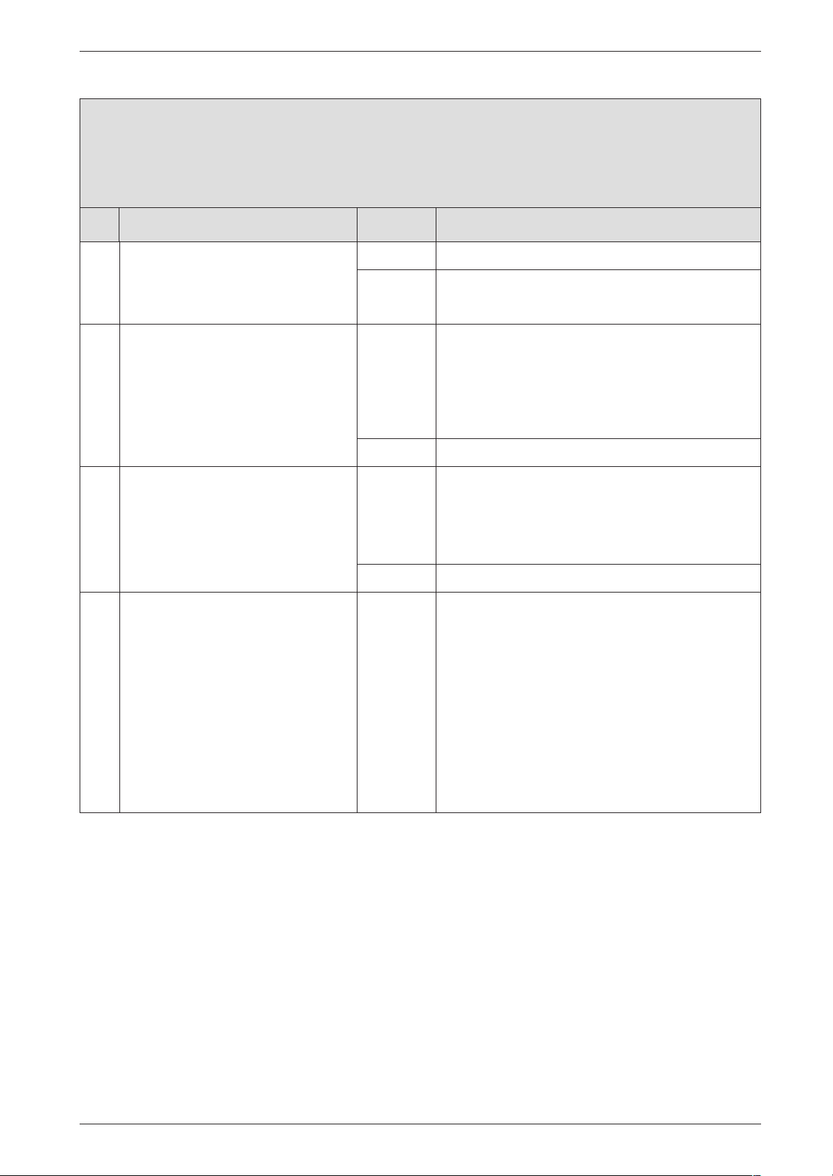
d3 flashing.
Wrong signal from pin 8-9 (open?).
Check Action
Failure identification procedure
1. B Turn ON the appliance.
B Measure voltage between Termi-
nal 4 and Terminal 8.
Voltage ≅ 24 V DC?
2. Existing heat store thermostat connected to Terminals 7, 8 and 9?
3. Break in connecting lead? yes: B Power OFF the appliance.
4. The PCB control board is damaged. B Make a note of the altered service settings (see
yes: ↓2.
no: ↓3.
yes: B Power OFF the appliance.
B Fix the additional bridge 8-9 in the right position
and close the screws.
B Turn ON the appliance.
d3? ↓3.
no: ↓4.
B Plug the connection wire.
B Turn ON the appliance.
d3? ↓4.
no: ↓4.
table 1, "First Service Level; Values that can be
modified" at page 8 and table 5, "Secondary
Service Level; Values that can be modified" at
page 11).
B Power OFF the appliance.
B Disconnect the boiler electrical connection.
B Change PCB control board.
B Reconnect the boiler electrical connection.
B Turn ON the appliance.
B Restore service settings previously noted down.
7 181 465 346 GB (03.02)
27
Page 72
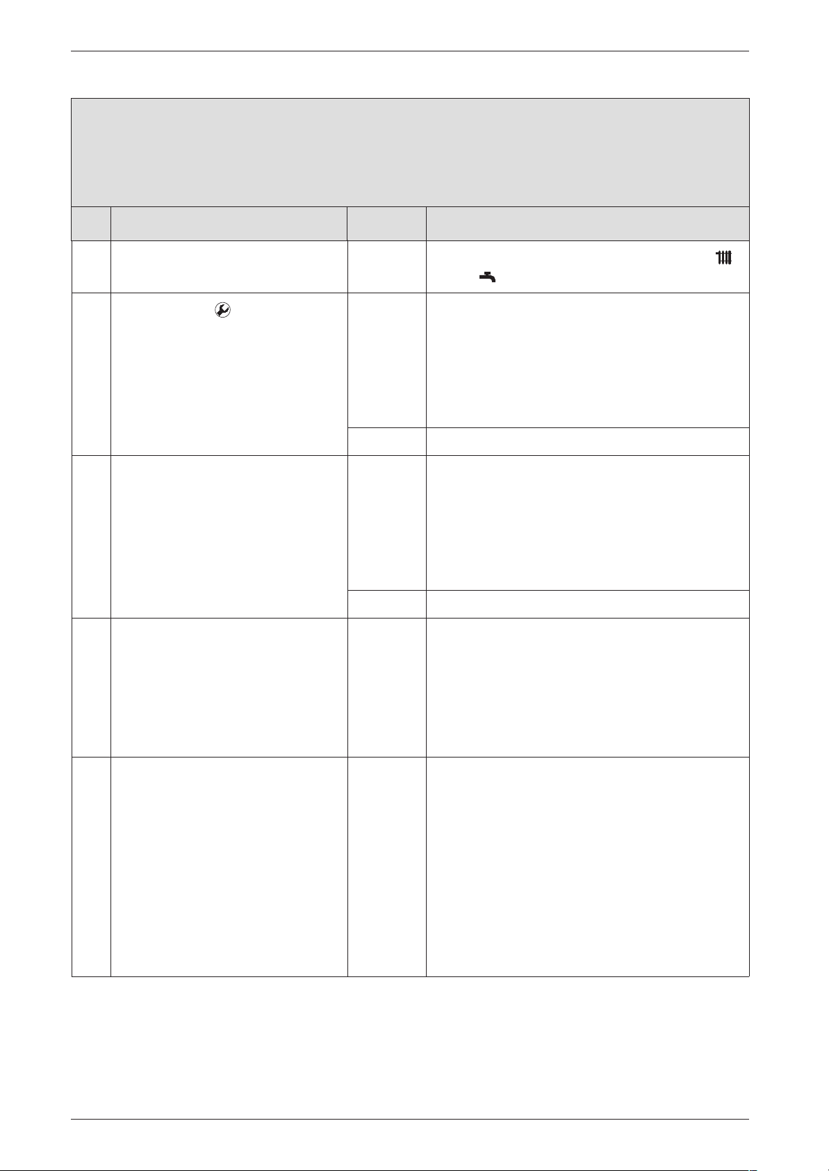
Failure identification procedure
E2 flashing.
The heating outlet NTC sensor is damaged.
Check Action
B Note the setting of the temperature controls
and .
1.
B Press button .
B Select service function .1 .
Is a temperature between 0. and
5. displayed?
2. Temperature for heating outlet NTC
sensor between 95. and 99. is displayed.
3. Check if the 20-pin connector lead
assembly is damaged.
yes: The heating outlet NTC sensor is in short circuit:
B Power OFF the appliance.
B Replace CH flow NTC sensor; observe fitting
instructions for NTC sensor when doing so.
B Turn ON the appliance.
E2? ↓2.
no: ↓2.
yes: The CH flow NTC sensor is interrupted :
B Power OFF the appliance.
B Replace CH flow NTC sensor; observe fitting
instructions for NTC sensor when doing so.
B Turn ON the appliance.
E2? ↓3.
no: ↓3.
B Power OFF the appliance.
B Disconnect the boiler electrical connection.
B Change the 20-pin connector lead assembly.
B Reconnect the boiler electrical connection.
B Turn ON the appliance.
E2? ↓4.
4. The PCB control board is damaged. B Make a note of the altered service settings (see
table 1, "First Service Level; Values that can be
modified" at page 8 and table 5, "Secondary
Service Level; Values that can be modified" at
page 11).
B Power OFF the appliance.
B Disconnect the boiler electrical connection.
B Change PCB control board.
B Reconnect the boiler electrical connection.
B Turn ON the appliance.
B Restore service settings previously noted down.
28
7 181 465 346 GB (03.02)
Page 73
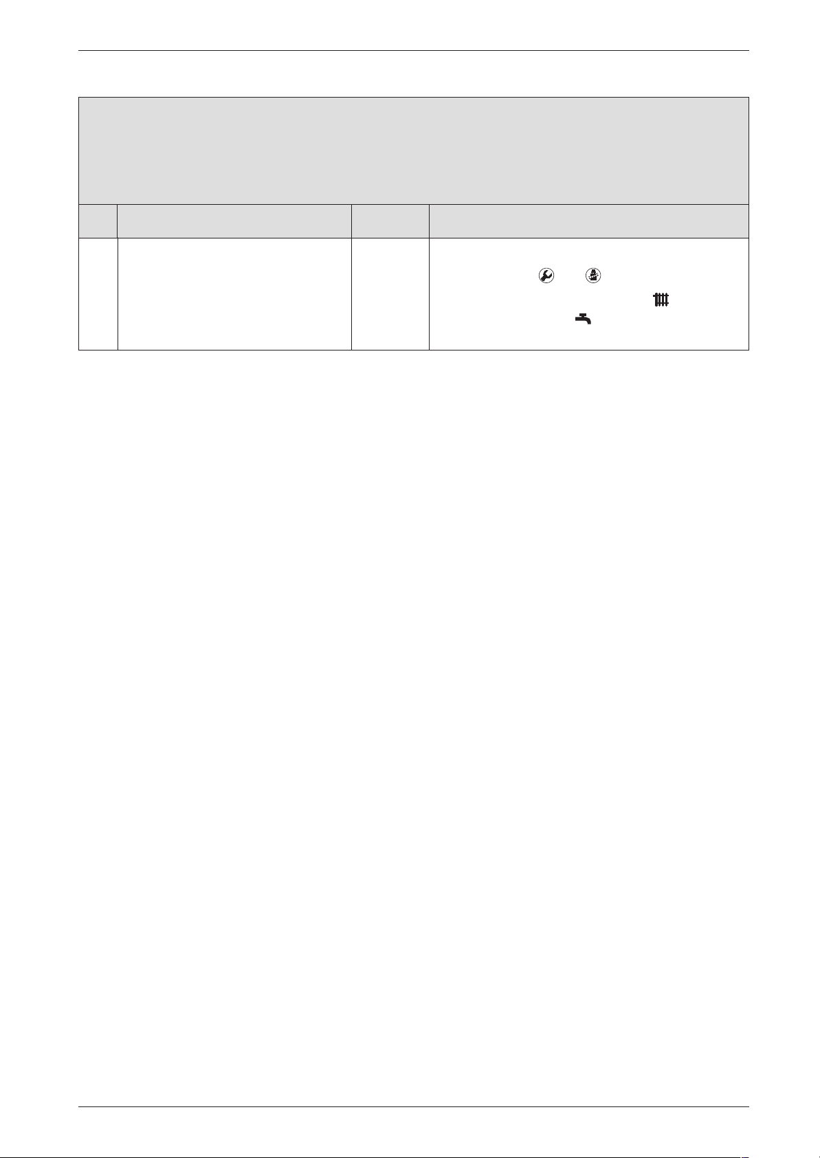
E2 flashing.
The heating outlet NTC sensor is damaged.
Check Action
Failure identification procedure
To return to normal function mode:
B Press buttons and simultaneously.
B Regulate the temperature control and the
temperature control on the previously set
positions.
7 181 465 346 GB (03.02)
29
Page 74
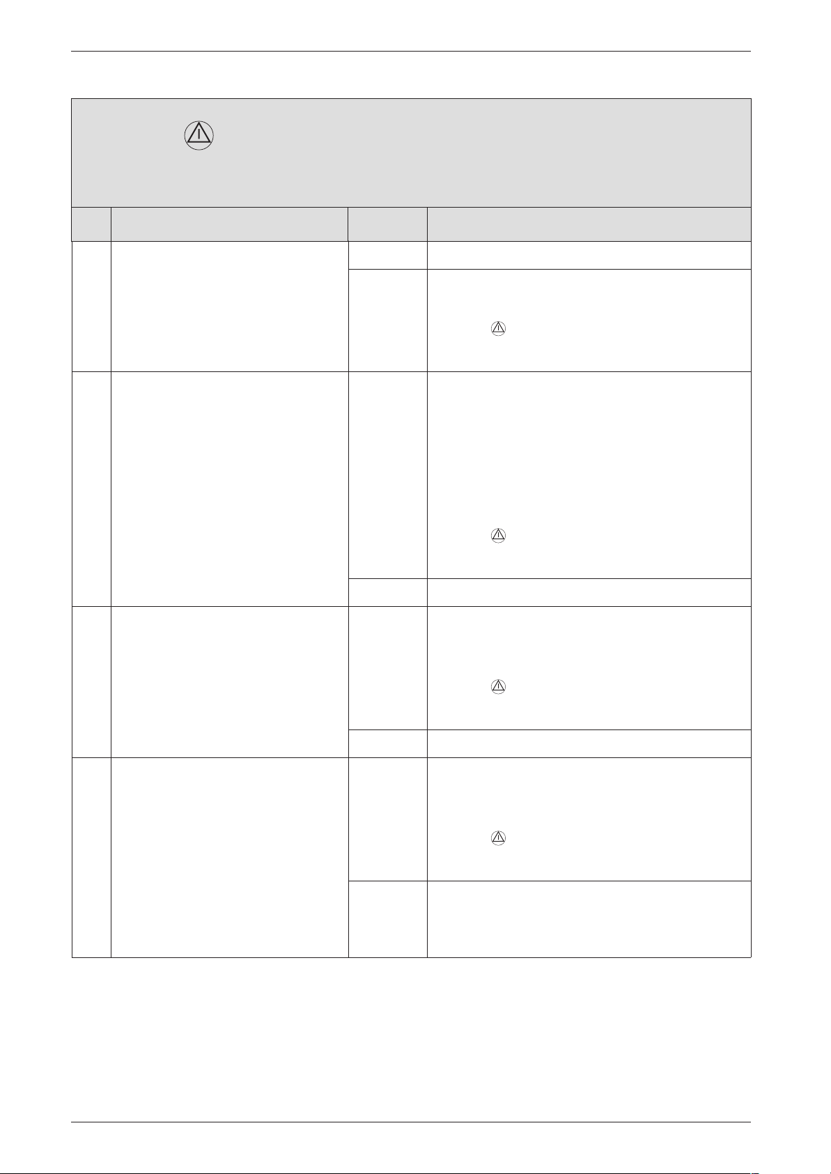
Failure identification procedure
E9 and flashing.
Safety temperature limiter has tripped.
Check Action
1. Is the heating pressure between 1
and 2 bar?
2. Is the pump blocked? yes: B Unblock the pump.
3. Lead disconnected from safety temperature limiters?
yes: ↓2.
no: B Top up system.
B Vent appliance.
B Press , restart the appliance.
E9? ↓2.
If pump won’t start:
B Power OFF the appliance.
B Disconnect the boiler electrical connection.
B Change the pump.
B Reconnect the boiler electrical connection.
B Turn ON the appliance.
B Press , restart the appliance.
E9? ↓3.
no: ↓3.
yes: B Power OFF the appliance.
B Connect lead.
B Turn ON the appliance.
4. B Power OFF the appliance.
B Unplug the connector from the
cut-off device.
B Measure the NTC electrical resist-
ance.
R = ∞?
B Press , restart the appliance.
E9? ↓4.
no: ↓4.
yes: B Change the over heating cut-off device.
B Connect flue gas safety temperature limiter lead.
B Turn ON the appliance.
B Press , restart the appliance.
E9? ↓5.
no: B Connect flue gas safety temperature limiter lead.
B Turn ON the appliance.
↓5.
30
7 181 465 346 GB (03.02)
Page 75
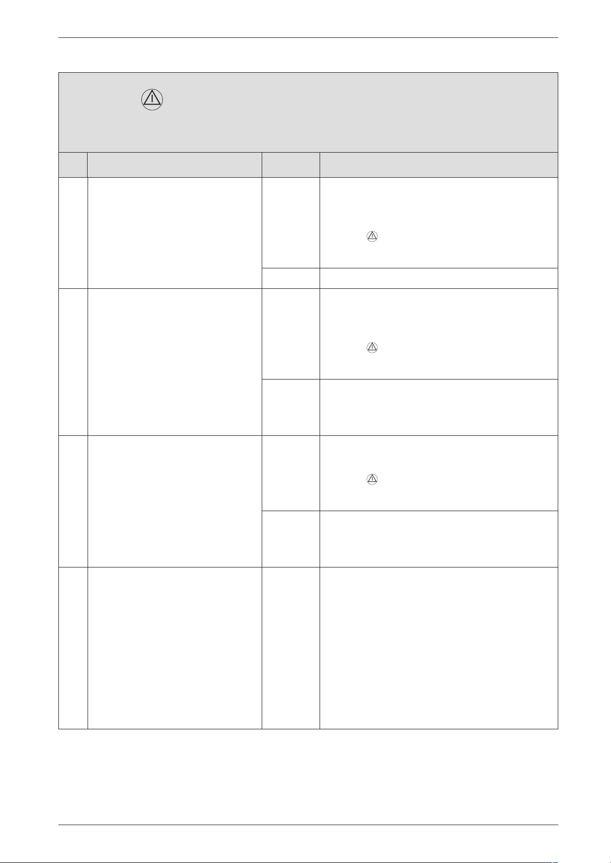
E9 and flashing.
Safety temperature limiter has tripped.
Check Action
Failure identification procedure
5. Is lead disconnected from CH flow
safety temp. limiter?
6. B Power OFF the appliance.
B Disconnect lead to CH flow safety
temperature limiter.
B Measure the CH flow safety tem-
perature limiter.
R = ∞?
7. B Power OFF the appliance.
B Remove fuse SI 3 from appliance
PCB control board and test for
continuity.
R = ∞?
yes: B Power OFF the appliance.
B Reconnect lead.
B Turn ON the appliance.
B Press , restart the appliance.
↓6.
no: ↓6.
yes: B Change CH flow safety temperature limiter.
B Connect CH flow safety temperature limiter lead.
B Turn ON the appliance.
B Press , restart the appliance.
E9? ↓7.
no: B Connect CH flow safety temperature limiter lead.
B Turn ON the appliance.
↓7.
yes: B Change the fuse.
B Turn ON the appliance.
B Press , restart the appliance.
E9? ↓8.
no: B Remount the fuse.
B Turn ON the appliance.
↓8.
8. The PCB control board is damaged. B Make a note of the altered service settings (see
table 1, "First Service Level; Values that can be
modified" at page 8 and table 5, "Secondary
Service Level; Values that can be modified" at
page 11).
B Power OFF the appliance.
B Disconnect the boiler electrical connection.
B Change PCB control board.
B Reconnect the boiler electrical connection.
B Turn ON the appliance.
B Restore service settings previously noted down.
7 181 465 346 GB (03.02)
31
Page 76
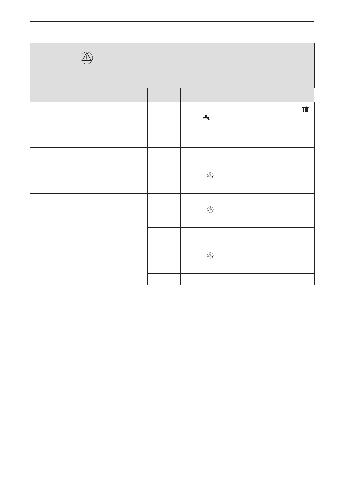
Failure identification procedure
EA and flashing.
No flame ionisations signal
Check Action
1. Is the flame present? yes: ↓6.
no: ↓2.
2. Is the gas cock open? yes: ↓3.
no: B Open the gas cock.
B Note the setting of the temperature controls
and .
B Press , restart the appliance.
EA? ↓3.
3. Is there air in the supply pipe? yes: B Vent supply pipe.
B Press , restart the appliance.
EA? ↓4.
no: ↓4.
4. Did the thermal security of the gas
cock lock out?
yes: B Reset security.
B Press , restart the appliance.
EA? ↓5.
no: ↓5.
32
7 181 465 346 GB (03.02)
Page 77
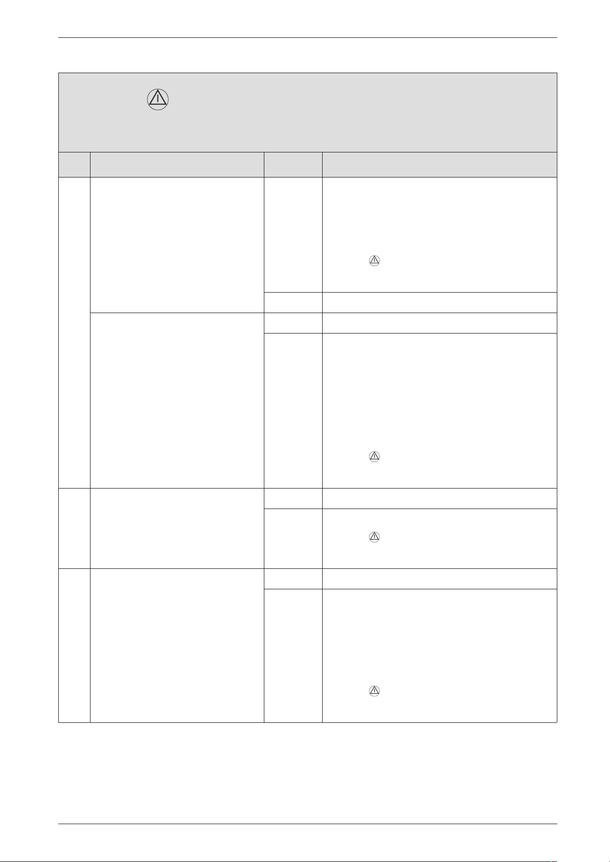
EA and flashing.
No flame ionisations signal
Check Action
Failure identification procedure
5. Natural gas models:
does the building have a supply pressure regulator?
LPG models:
is the flow rate of the gas supply to
the appliance correct?
yes: B Check that it is fitted correctly and functioning
properly and correct if necessary.
B Check supply pressure, inform gas company if
outside correct range.
B Is correct code plug fitted?
B Press , restart the appliance.
EA? ↓6.
no: ↓6.
yes: ↓6.
no: B Is there enough gas in the supply cylinder?
B Is there air in the supply pipe?
B Is the solenoid valve in the "meter cabinet” open-
ing?
B Is the supply pressure OK? (if the supply pres-
sure is too high, check the pressure regulator in
the “meter cabinet” and on the LPG supply cylinder).
B Press , restart the appliance.
EA? ↓6.
6. Is the ground connection correct? yes: ↓7.
no: B Correct the electrical ground connection.
B Press , restart the appliance.
EA? ↓7.
7. Two phase net:
Is there a resistor fitted between Pe
and N?
yes: ↓8.
no: B Power OFF the appliance.
B Disconnect the boiler electrical connection.
B Insert a 2 MΩ resistance between the ground
B Reconnect the boiler electrical connection.
B Turn ON the appliance.
B Press , restart the appliance.
EA? ↓11.
and the N connection.
7 181 465 346 GB (03.02)
33
Page 78
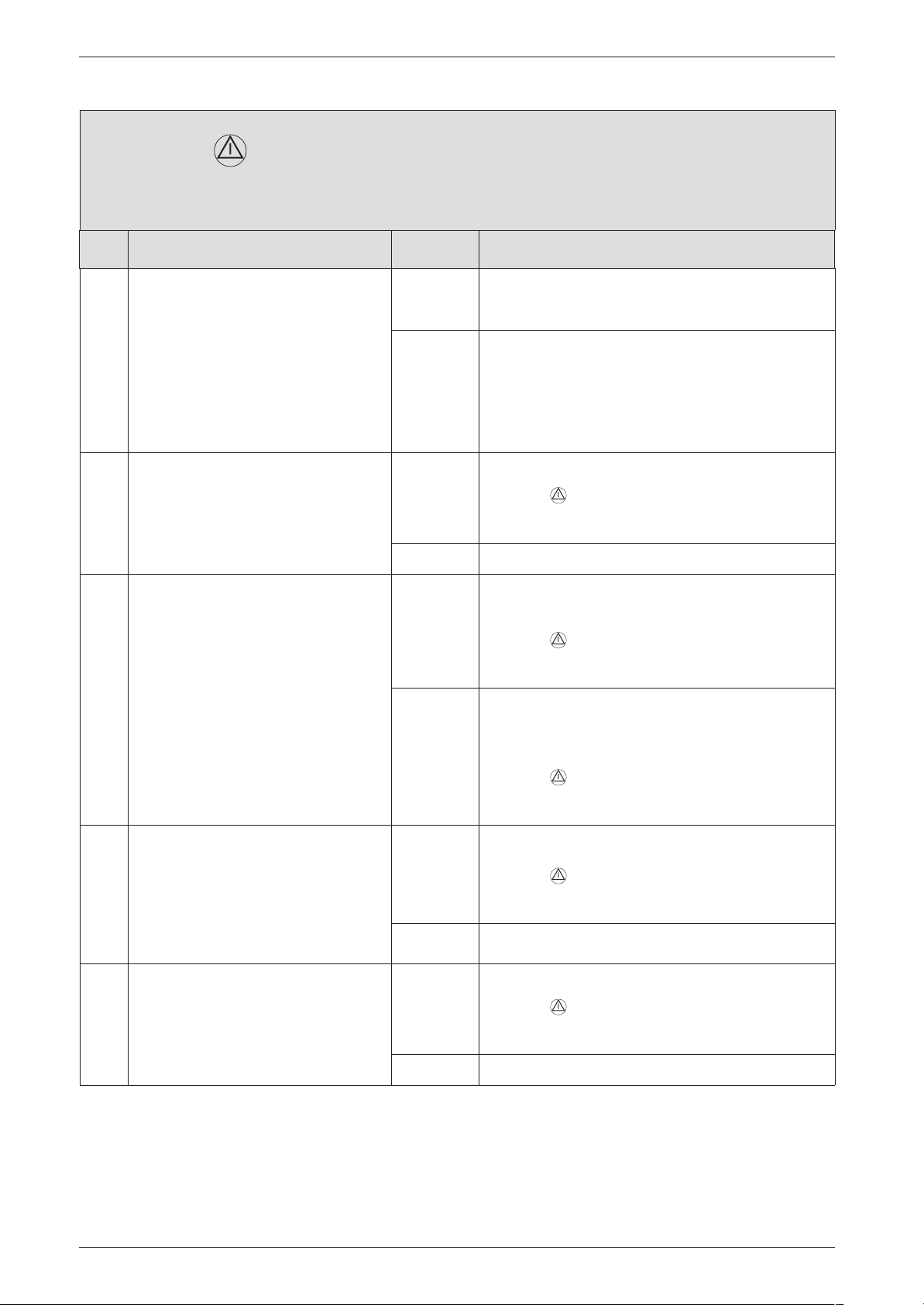
Failure identification procedure
EA and flashing.
No flame ionisations signal
Check Action
8. Is diaphragm in the mixer unit correctly fitted and functional?
B Open mixer unit (29).
B Check diaphragm for correct ori-
entation, soiling and splitting.
Is diaphragm OK?
9. Is the condensation trap blocked? yes: B Clean out condensation trap discharge pipe.
10. Check the gas valve?
B Power OFF the appliance.
B Unplug the connectors from the
gas valve.
B Measure the gas valve coils I and
II electrical resistance.
R = 164 ± 40Ω ?
yes: B Close mixer unit.
↓9.
no: B Insert diaphragm in the fan intake duct as per
installation instructions so that the flaps open
upwards.
B Close mixer unit.
EA? ↓9.
B Press , restart the appliance.
EA? ↓13.
no: ↓10.
yes: B Reconnect the gas valve.
B Turn ON the appliance.
B Press , restart the appliance.
EA? ↓11.
no: B Change the gas valve.
B Reconnect the gas valve.
B Turn ON the appliance.
11. Problem with flue?
B Check CO2 level in combustion
air.
Is CO2 level above 0,2 % ?
B Open up heat exchanger - is it
dirty?
12.
Is flue gas CO2 level incorrect1)?
B Press , restart the appliance.
EA? ↓11.
yes: B Check flue and clean if necessary.
B Press , restart the appliance.
EA? ↓12.
no: ↓12.
yes: B Adjust to correct level.
B Press , restart the appliance.
EA? ↓13.
no: ↓13.
34
7 181 465 346 GB (03.02)
Page 79
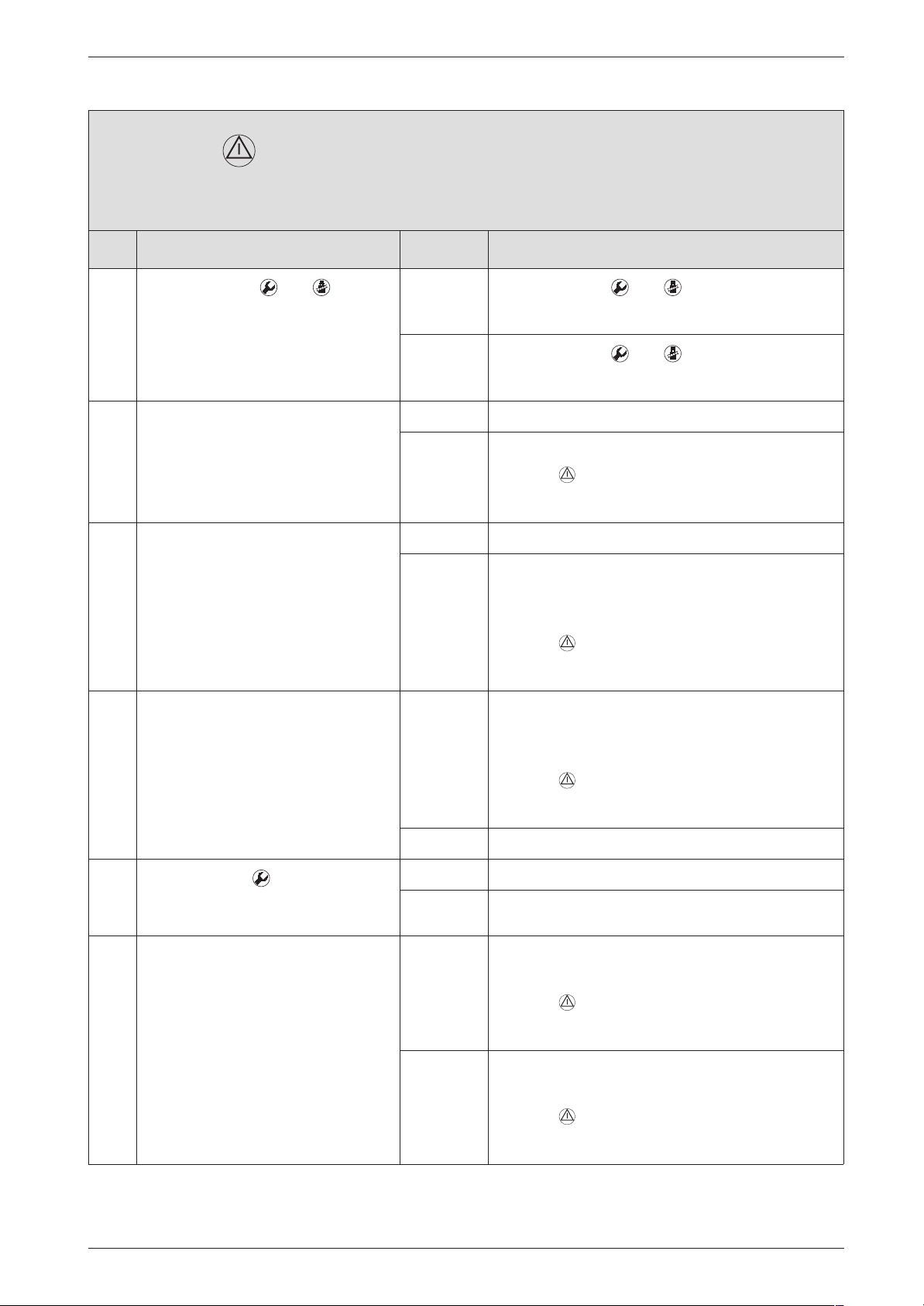
EA and flashing.
No flame ionisations signal
Check Action
Failure identification procedure
13.
14. Ignition lead connected to ignition
15. Ignition cable connector engaged in
16. Is the ignition electrical wire
B Press buttons and simulta-
neously.
B Select service-function 5.1.
Continuous ignition (without gas)
OK?
electrodes?
switchbox?
damaged?
yes:
no:
yes: ↓15.
no: B Connect cable to ignition electrode.
yes: ↓16.
no: B Power OFF the appliance.
yes: B Power OFF the appliance.
B Press buttons and simultaneously.
↓14.
B Press buttons and simultaneously.
↓17.
B Press , restart the appliance.
EA? ↓15.
B Engage ignition cable connector in switchbox.
B Turn ON the appliance.
B Press , restart the appliance.
EA? ↓16.
B Change the ignition electrical wire.
B Turn ON the appliance.
17.
18. Electrode assembly defective?
B Press button .
B Select service-function 3.3.
Is the ionisation quality 2. or 3. ?
B Power OFF the appliance.
B Remove electrode assembly.
Electrodes worn out?
B Press , restart the appliance.
EA? ↓17.
no: ↓17.
yes: ↓19.
no: ↓18.
yes: B Replace electrode assembly.
B Turn ON the appliance.
B Press , restart the appliance.
EA? ↓19.
no: B Refit electrode assembly.
B Turn ON the appliance.
B Press , restart the appliance.
EA? ↓19.
7 181 465 346 GB (03.02)
35
Page 80
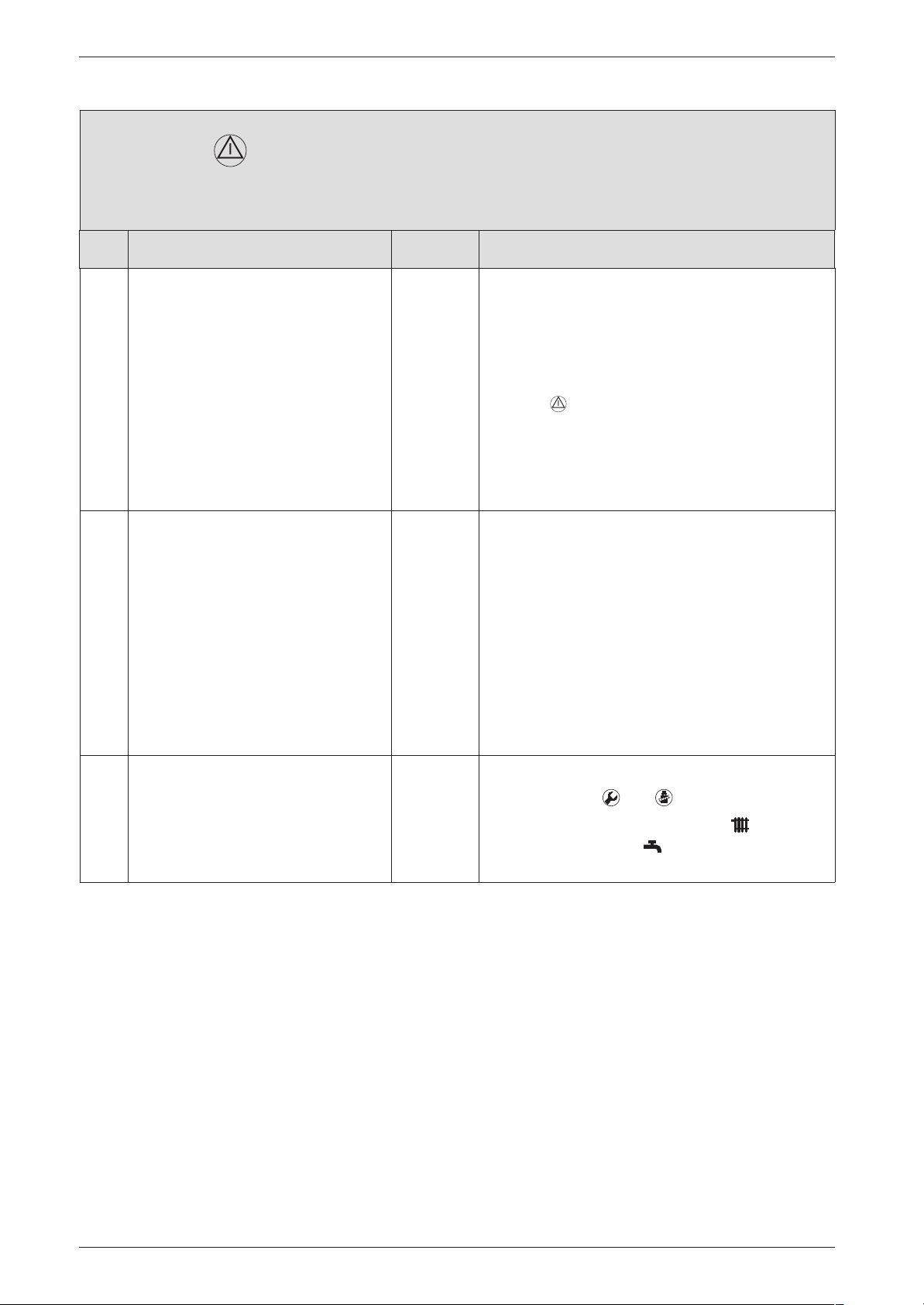
Failure identification procedure
EA and flashing.
No flame ionisations signal
Check Action
19. Check if the 20-pin connector lead
assembly is damaged.
20. The PCB control board is damaged. B Make a note of the altered service settings (see
B Power OFF the appliance.
B Disconnect the boiler electrical connection.
B Change the 20-pin connector lead assembly.
B Turn ON the appliance.
B Reconnect the boiler electrical connection.
B Press , restart the appliance.
EA?
B Power OFF the appliance.
↓20.
table 1, "First Service Level; Values that can be
modified" at page 8 and table 5, "Secondary
Service Level; Values that can be modified" at
page 11).
B Power OFF the appliance.
B Disconnect the boiler electrical connection.
B Change PCB control board.
B Reconnect the boiler electrical connection.
B Turn ON the appliance.
B Restore service settings previously noted down.
1) See installation instructions
To return to normal function mode:
B Press buttons and simultaneously.
B Regulate the temperature control and the
temperature control on the previously set
positions.
36
7 181 465 346 GB (03.02)
Page 81
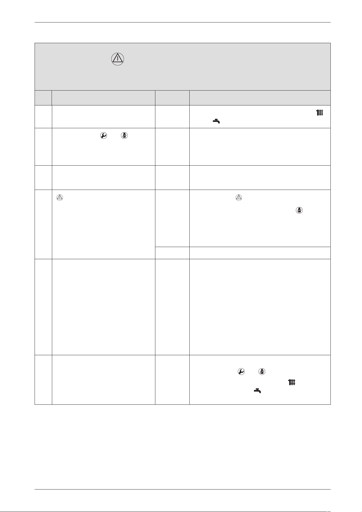
F0 (and possibly ) flashing.
Internal failure
Check Action
Failure identification procedure
B Note the setting of the temperature controls
and .
1.
B Press buttons and simulta-
neously.
B Select service function 9.3 .
A service code is displayed.
2. B Select service function 5.2 .
A service code is displayed.
3.
4. The PCB control board is damaged. B Make a note of the altered service settings (see
flashing?
yes:
no: ↓4.
B Enter figure displayed in customer service record.
↓2.
B Enter figure displayed in customer service record.
↓3.
B Press button .
B Initiate demand for heat by pressing button
and then press again after 30 seconds to cancel.
B Initiate two more demands for heat as above.
F0? ↓4.
table 1, "First Service Level; Values that can be
modified" at page 8 and table 5, "Secondary
Service Level; Values that can be modified" at
page 11).
B Power OFF the appliance.
B Disconnect the boiler electrical connection.
B Change PCB control board.
B Reconnect the boiler electrical connection.
B Turn ON the appliance.
B Restore service settings previously noted down.
7 181 465 346 GB (03.02)
To return to normal function mode:
B Press buttons and simultaneously.
B Regulate the temperature control and the
temperature control on the previously set
positions.
37
Page 82
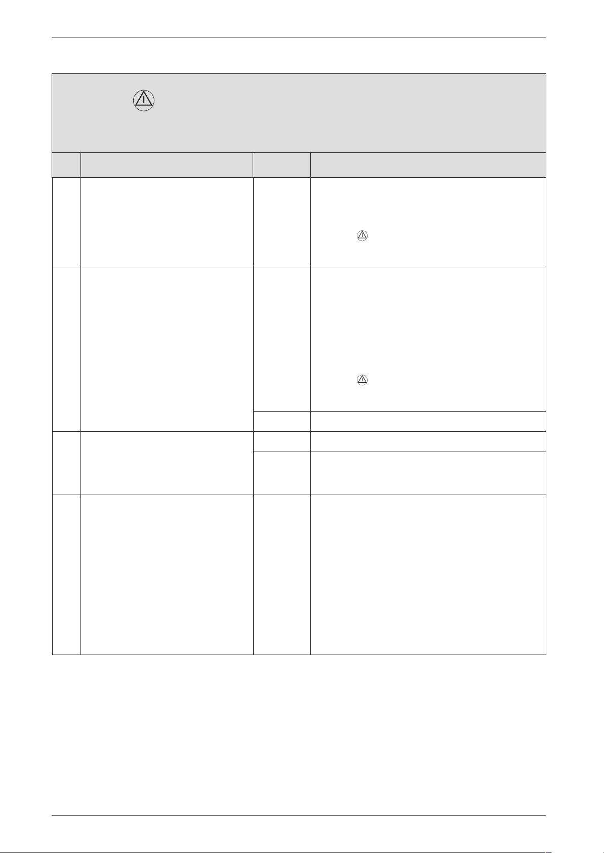
Failure identification procedure
F7 and flashing.
Although appliance switches off, flame still detected
Check Action
1. Electrode(s) dirty or defective. B Power OFF the appliance.
B Replace electrode assembly.
B Turn ON the appliance.
B Press , restart the appliance.
F7? ↓2.
2. B Power OFF the appliance.
B Disconnect the boiler electrical
connection.
B Remove PCB control board.
PCB control board damp?
3. Problem with flue?
B Check CO2 level in combustion
air.
Is CO2 level above 0,2 % ?
4. The PCB control board is damaged. B Make a note of the altered service settings (see
yes: B Dry PCB control board (e.g. with hair dryer).
B Look for point where damp is entering switchbox
and seal as necessary (cable grommets properly
fitted, ...?).
B Refit PCB control board.
B Reconnect the boiler electrical connection.
B Turn ON the appliance.
B Press , restart the appliance.
F7? ↓3.
no: ↓3.
yes: B Check flue and repair or replace if necessary.
no: ↓4.
table 1, "First Service Level; Values that can be
modified" at page 8 and table 5, "Secondary
Service Level; Values that can be modified" at
page 11).
B Power OFF the appliance.
B Disconnect the boiler electrical connection.
B Change PCB control board.
B Reconnect the boiler electrical connection.
B Turn ON the appliance.
B Restore service settings previously noted down.
38
7 181 465 346 GB (03.02)
Page 83
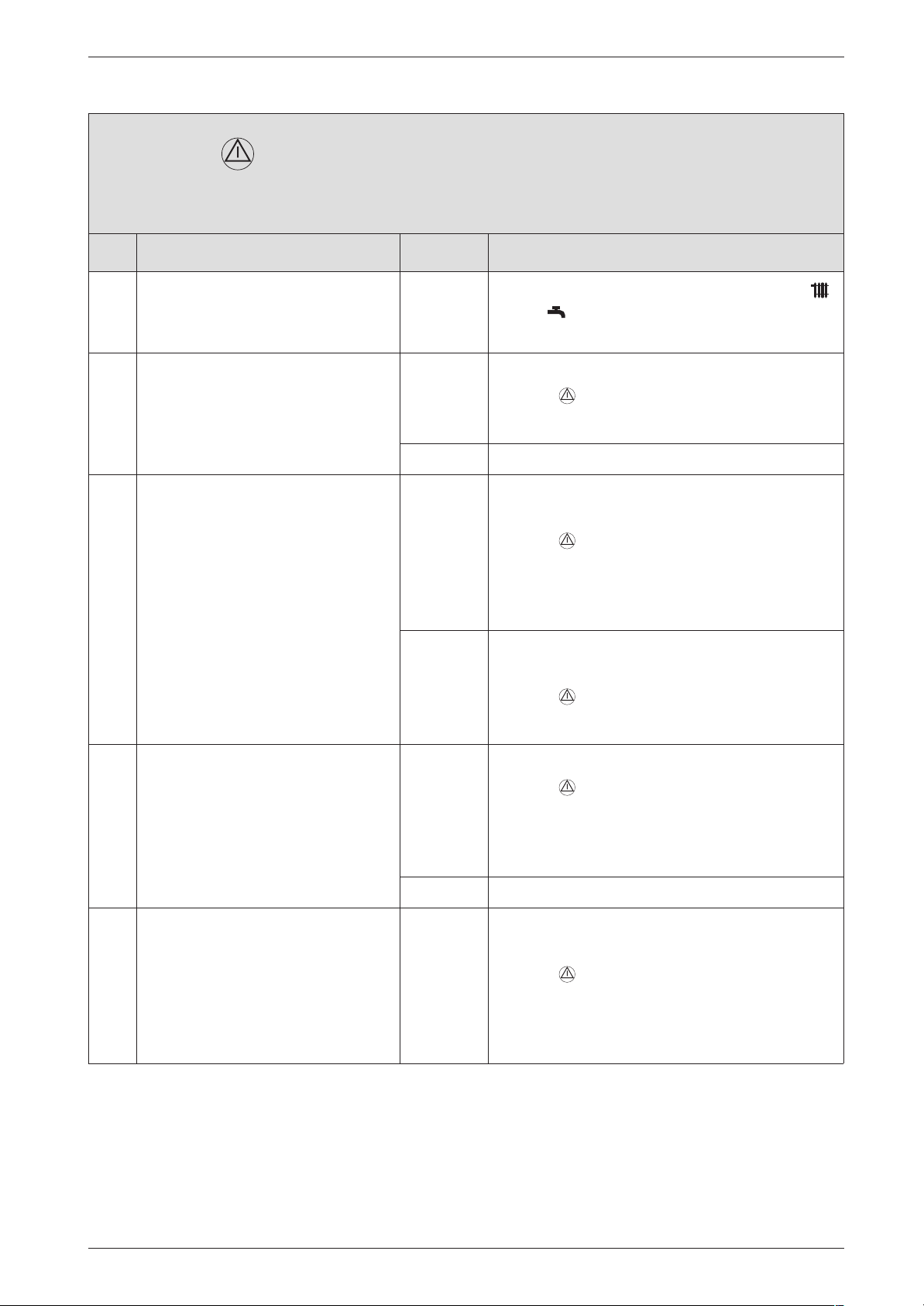
Failure identification procedure
FA and flashing.
Although appliance switches off, flame still detected
Check Action
B Note the setting of the temperature controls
and .
B Power OFF the appliance.
1. Condensation trap blocked? yes: B Clean condensation trap discharge pipe.
B Press , restart the appliance.
FA? ↓2.
no: ↓2.
2. Electrode assembly defective?
B Power OFF the appliance.
B Remove electrode assembly.
Electrode assembly burnt out?
3. Problem with flue?
B Check CO2 level in combustion
air.
Is CO2 level above 0,2 % ?
4. The gas valve is damaged. B Change the gas valve.
yes: B Replace electrode assembly.
B Turn ON the appliance.
B Press , restart the appliance.
FA?
B Power OFF the appliance.
↓3.
no: B Refit electrode assembly.
B Turn ON the appliance.
B Press , restart the appliance.
FA? ↓3.
yes: B Check flue and repair or replace if necessary.
B Press , restart the appliance.
FA?
B Power OFF the appliance.
↓4.
no: ↓4.
B Turn ON the appliance.
7 181 465 346 GB (03.02)
B Press , restart the appliance.
FA?
B Power OFF the appliance.
↓5.
39
Page 84
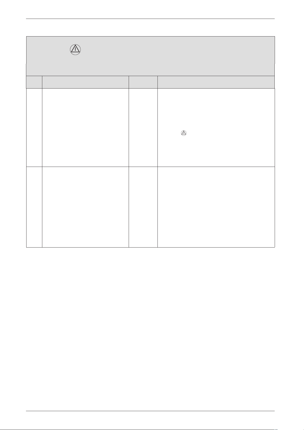
Failure identification procedure
FA and flashing.
Although appliance switches off, flame still detected
Check Action
5. Check if the 20-pin connector lead
assembly is damaged.
6. The PCB control board is damaged. B Make a note of the altered service settings (see
B Power OFF the appliance.
B Disconnect the boiler electrical connection.
B Change the 20-pin connector lead assembly.
B Turn ON the appliance.
B Reconnect the boiler electrical connection.
B Press , restart the appliance.
FA?
B Power OFF the appliance.
↓6.
table 1, "First Service Level; Values that can be
modified" at page 8 and table 5, "Secondary
Service Level; Values that can be modified" at
page 11).
B Power OFF the appliance.
B Disconnect the boiler electrical connection.
B Change PCB control board.
B Reconnect the boiler electrical connection.
B Turn ON the appliance.
B Restore service settings previously noted down.
40
7 181 465 346 GB (03.02)
Page 85
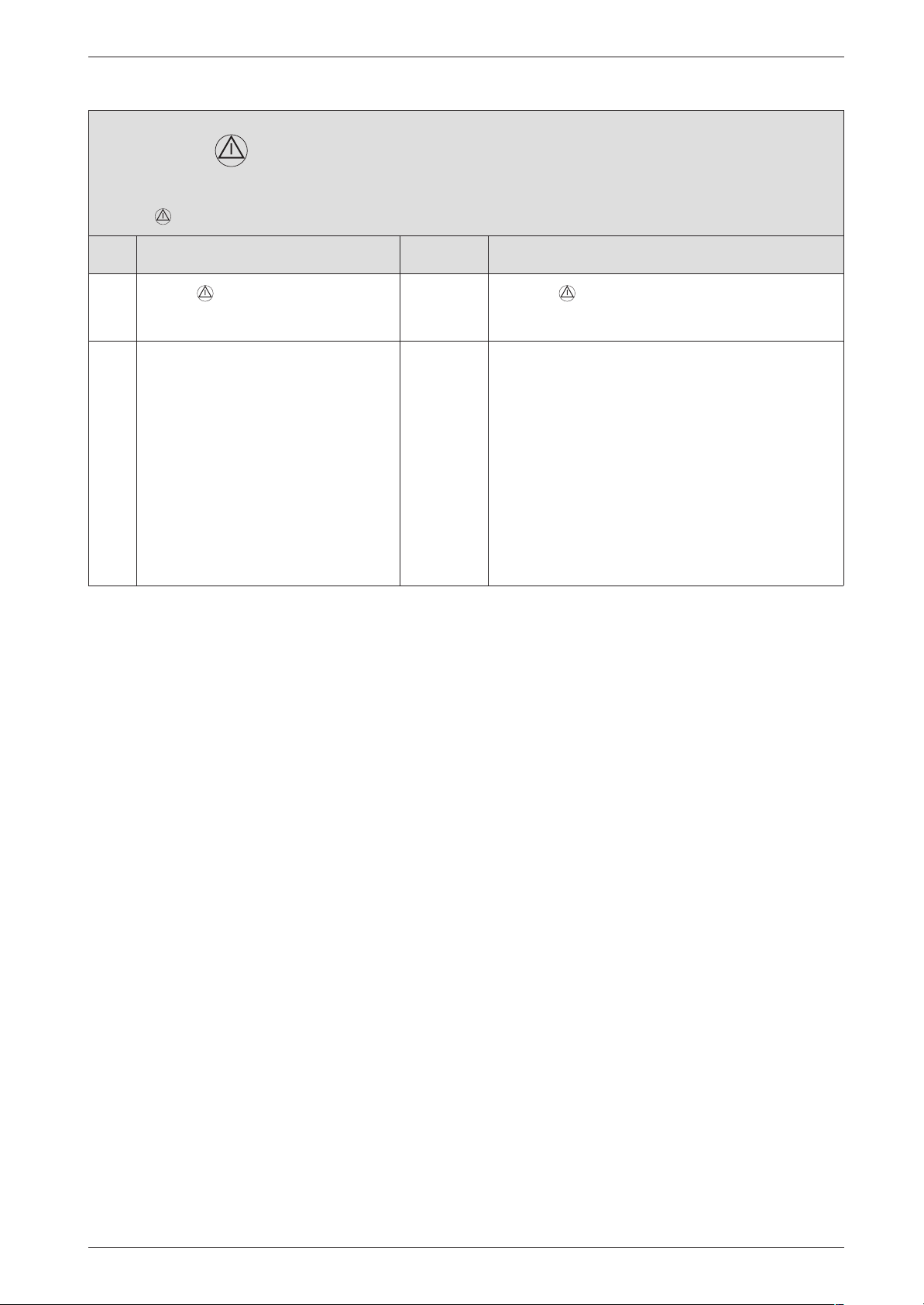
Fd and flashing.
Button pressed without necessity
Check Action
Failure identification procedure
1.
2. The PCB control board is damaged. B Make a note of the altered service settings (see
Button is flashing. B Press , restart the appliance.
Fd? ↓2.
table 1, "First Service Level; Values that can be
modified" at page 8 and table 5, "Secondary
Service Level; Values that can be modified" at
page 11).
B Power OFF the appliance.
B Disconnect the boiler electrical connection.
B Change PCB control board.
B Reconnect the boiler electrical connection.
B Turn ON the appliance.
B Restore service settings previously noted down.
7 181 465 346 GB (03.02)
41
Page 86
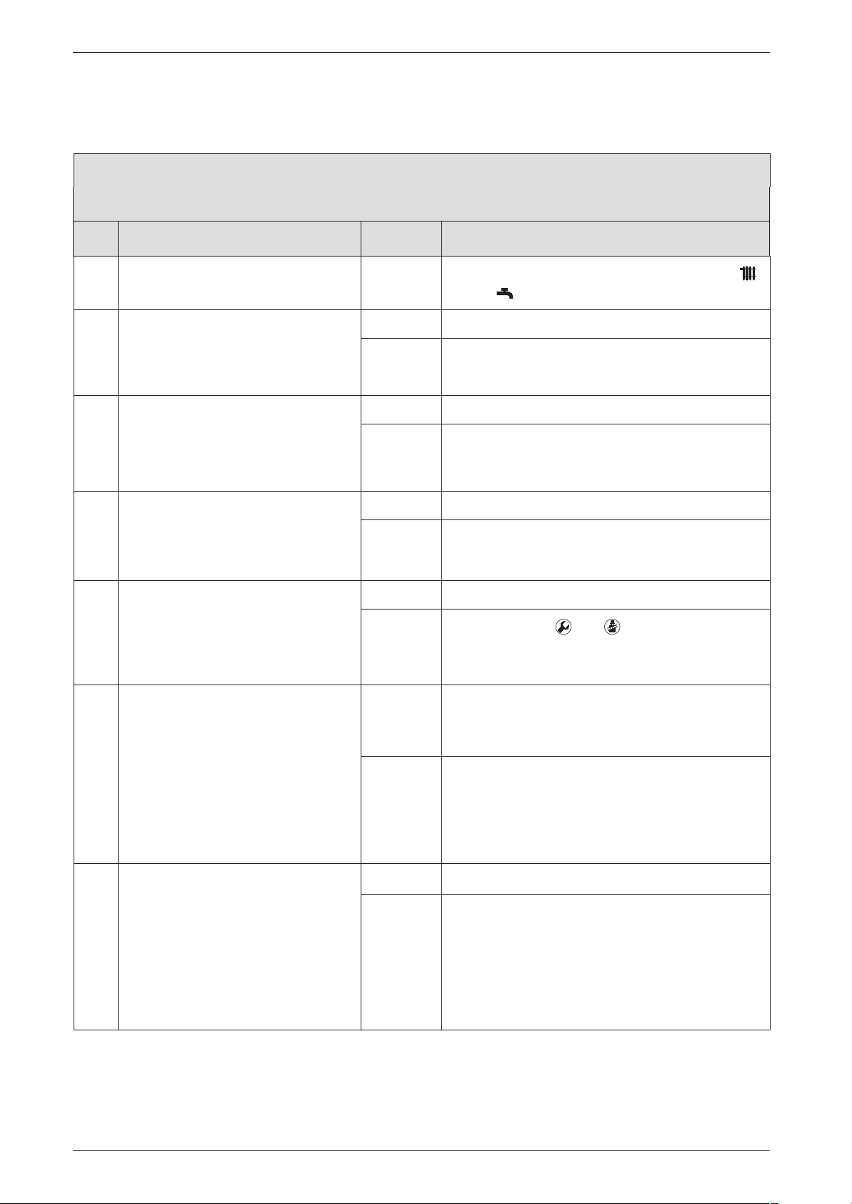
Failure identification procedure
3.4 Faults that are not displayed
3.4.1 Appliance faults
Excessive burner noise, rumbling noises
Check Action
B Note the setting of the temperature controls
and .
1. Does the gas supply type match the
specifications on the appliance identification plate?
2. B Test gas supply pressure - OK?
Does pressure match figure specified in installation instructions?
3. Problem with flue?
B Check CO
level in combustion
2
air.
Is CO2 level above 0,2 % ?
4. Cascade system:
Is the appliance min. output high
enough to open the shut-off device?
5. Is appliance’s internal air/flue channel leaking or blocked?
B Open up heat exchanger and
inspect.
B Remove silencer, flue duct and air
flow limit.
B Open trap and inspect.
Air channels dirty/clogged, seals
defective or not correctly fitted?
yes: ↓2.
no: B Convert appliance to correct gas type.
↓2.
yes: ↓3.
no: B Decommission appliance.
For natural gas:
B Notify gas company.
yes: B Check flue and repair or replace if necessary.
no: ↓3.
yes: ↓5.
no:
B Press buttons and simultaneously.
B Select Service Function 5.5 .
B Increase min. output.
yes: B Repair or replace components.
B Grease seal before fitting.
B Make sure it is fitted in correct position.
no: ↓6.
6. B Measure CO2 levels.
CO2 levels in flue gas at min and
max output do not match figures
specified in installation instructions.
42
yes: B Adjust CO2 level as per installation instructions.
no: B Turn off gas cock.
B Power OFF the appliance.
B Change the gas valve.
B Open the gas cock.
B Turn ON the appliance.
B Check appliance for leaks.
7 181 465 346 GB (03.02)
Page 87
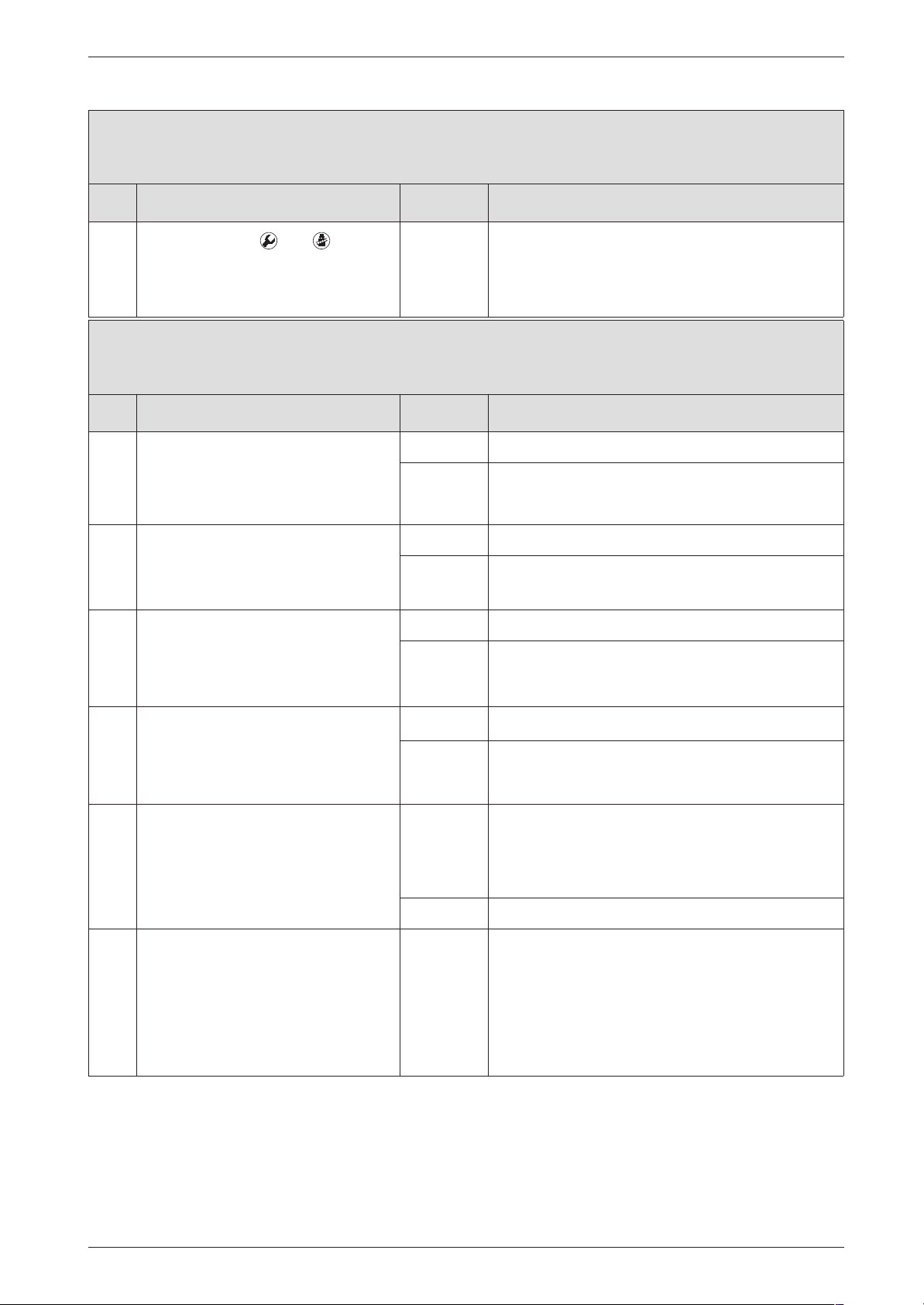
Excessive burner noise, rumbling noises
Check Action
Failure identification procedure
7.
B Press buttons and simulta-
B Set to 1 for high start-up speed.
neously.
B Select service-function 5.9.
0 is displayed.
Flue gas levels incorrect, CO level too high
Check Action
1. Does the gas supply type match the
yes: ↓2.
specifications on the appliance identification plate?
no: B Convert appliance to correct gas type.
↓2.
2. B Test gas supply pressure - OK? yes: ↓3.
no: B Decommission appliance.
B Notify gas company.
3. Problem with flue?
B Check CO2 level in combustion
yes: B Check flue and repair or replace if necessary.
no: ↓4.
air.
Is CO
level above 0,2 % ?
2
4. Flue gas CO
levels measured at
2
yes: B Adjust CO2 levels.
min. and max. load do not match
specified levels?
no: ↓5.
B Measure CO2 levels.
5. Gas volumetric flow too high when
CO2 level correctly set.
yes: B Reduce gas volumetric flow rate by means of
adjusting screw on gas valve and/or gas flow
restrictor.
B Check CO2 adjustment.
no: ↓6.
6. B Turn off gas cock.
B Power OFF the appliance.
B Change the gas valve.
B Open the gas cock.
B Turn ON the appliance.
B Check appliance for leaks.
7 181 465 346 GB (03.02)
43
Page 88
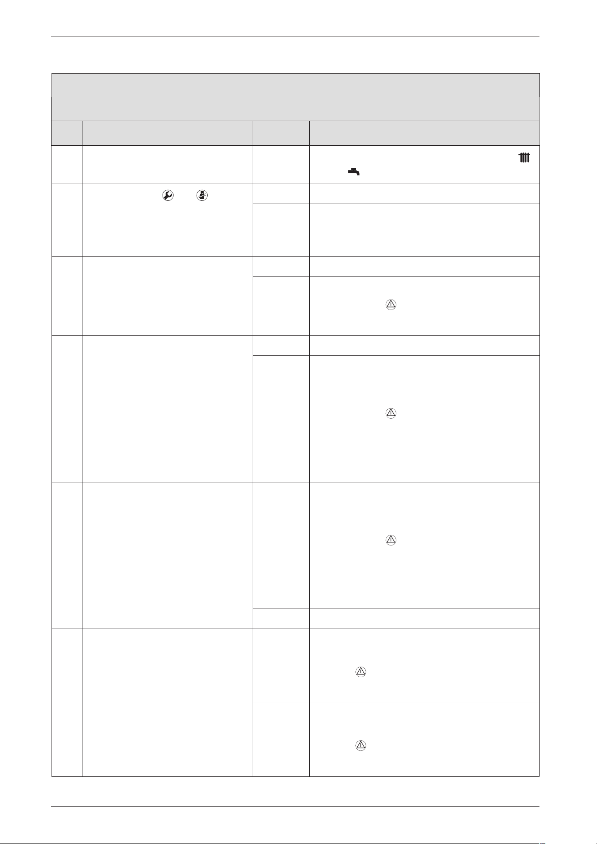
Failure identification procedure
Ignition too harsh, ignition poor
Check Action
B Note the setting of the temperature controls
and .
1.
B Press buttons and simulta-
neously.
B Select service-function 5.1.
Continuous ignition (without gas)
OK?
2. Ignition lead connected to ignition
electrodes?
3. Ignition cable connector engaged in
switchbox?
yes: ↓6.
no: ↓2.
yes: ↓3.
no: B Connect cable to ignition electrodes.
B Press button .
Ignition poor? ↓3.
yes: ↓4.
no: B Power OFF the appliance.
B Engage ignition cable connector in switchbox.
B Turn ON the appliance.
B Press button .
Ignition poor?
B Power OFF the appliance.
↓4.
4. Is the ignition electrical wire damaged?
5. Electrode assembly defective?
B Power OFF the appliance.
B Remove electrode assembly.
Electrodes worn out?
yes: B Power OFF the appliance.
B Change the ignition electrical wire.
B Turn ON the appliance.
B Press button .
Ignition poor?
B Power OFF the appliance.
↓5.
no: ↓5.
yes: B Replace electrode assembly.
B Turn ON the appliance.
B Press , restart the appliance.
Ignition poor? ↓6.
no: B Refit electrode assembly.
B Turn ON the appliance.
B Press , restart the appliance.
Ignition poor? ↓6.
44
7 181 465 346 GB (03.02)
Page 89
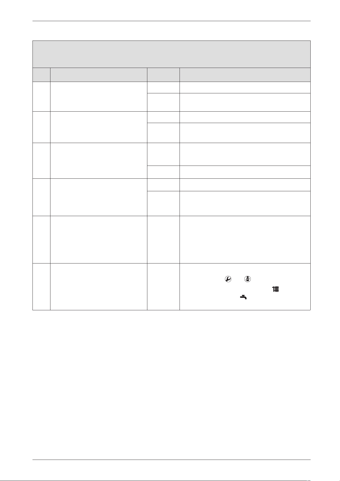
Ignition too harsh, ignition poor
Check Action
Failure identification procedure
6. Does the gas supply type match the
yes: ↓7.
specifications on the appliance identification plate?
no: B Carry out gas type conversion as described in
7. B Test gas supply pressure - OK? yes: ↓8.
no: B Decommission appliance.
B Notify gas company.
8. Problem with flue?
B Check CO2 level in combustion
yes: B Check flue and repair or replace if necessary.
↓9.
air.
Is CO2 level above 0,2 % ?
9. Flue gas CO2 levels measured at
no: ↓9.
yes: B Adjust CO2 level as per installation instructions.
min. and max. load do not match
specified levels.
no: ↓10.
B Measure CO2 levels.
10. Burner not correctly fitted or defective?
B Replace burner and seal if necessary.
B Ensure seal is fitted in correct position.
B Remove burner.
Cover fixings not tight or seal
defective or not correctly fitted or
burner defective!
installation instructions.
To return to normal function mode:
B Press buttons and simultaneously.
B Regulate the temperature control and the
temperature control on the previously set
positions.
7 181 465 346 GB (03.02)
45
Page 90
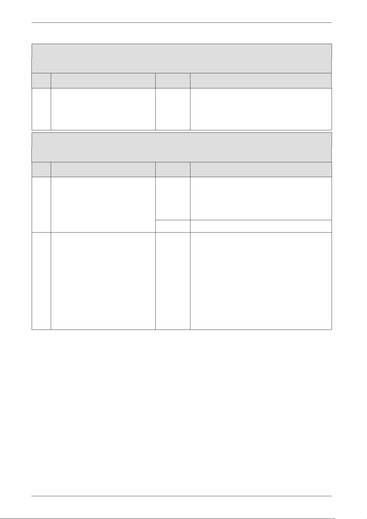
Failure identification procedure
Loose or broken contact on heat store NTC sensor
Check Action
1. Heat store NTC sensor lead is not
fitted as described in the installation
instructions (i.e. the cable does not
pass through the cable grip in the
B Record condition of appliance as found in cus-
tomer service record.
B Route cable as specified in installation instruc-
tions.
switchbox).
Boiler indicates P1, P2, P3 at start-up and then restarts with P1..
Check Action
1. Fuse T 1,6 A (312) defective. yes: B Turn ON the appliance.
B Change the fuse.
B Power OFF the appliance.
Start sequence not completed? ↓2.
no: ↓2.
2. The PCB control board is damaged. B Make a note of the altered service settings (see
table 1, "First Service Level; Values that can be
modified" at page 8 and table 5, "Secondary
Service Level; Values that can be modified" at
page 11).
B Power OFF the appliance.
B Disconnect the boiler electrical connection.
B Change PCB control board.
B Reconnect the boiler electrical connection.
B Turn ON the appliance.
B Restore service settings previously noted down.
46
7 181 465 346 GB (03.02)
Page 91
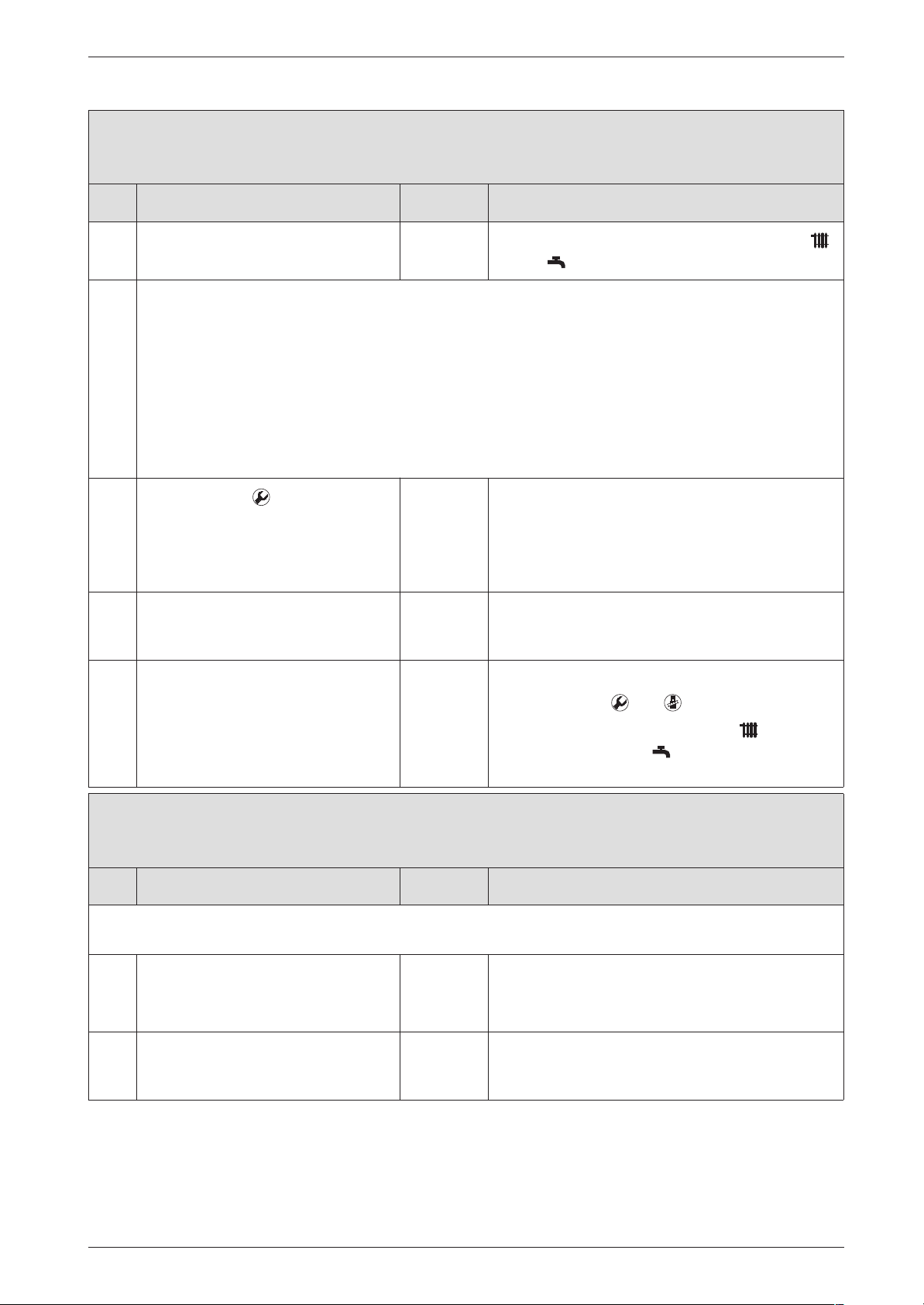
Specified CH flow temperature from TA... programmer exceeded
Check Action
B Note the setting of the temperature controls
and .
If outside-temperature controlled programmer (TA...) is connected to boiler:
• The anti-cycle time is adjusted by the programmer to the suit the system.
• The factory setting for the anti-cycle time (3 min.) and the heating mode hysteresis setting, if applicable, are deactivated.
• In cyclic mode, the switching of the boiler on or off is subject to a time delay in order to prevent divergence between the average CH flow temperature and the specified CH flow temperature.
As a result (depending on the heat draw), the specified CH flow temperature is briefly exceeded.
In extreme cases, it can happen that the burner does not switch off until the maximum CH flow temperature is reached even though a lower CH flow temperature has been specified.
Failure identification procedure
1.
B Press button .
B Select service-function 2.7.
B Disable automatic anti-cycle time, i.e. change
setting to 0.
Read off status of automatic anticycle time (0 = Disabled, 1 = Enabled).
2. B Select service-function 2.4.
Read off anti-cycle time setting
B Set anti-cycle time as required, e.g. factory set-
ting 3 min.
(0 ... 15 min).
To return to normal function mode:
B Press buttons and simultaneously.
B Regulate the temperature control and the
temperature control on the previously set
positions.
Hot water has unpleasant odour or is dark colour
Check Action
This is generally caused by the formation of hydrogen sulphide by sulphate-reducing bacteria. Such bacteria are
found in water which is very low in oxygen and live off the hydrogen produced by the anode.
1. B Clean the hot water cylinder.
B Replace the sacrificial anode.
B Heat cylinder to a temperature ≥60˚C
2. B Replace magnesium sacrificial anode with
impressed-current anode.
The conversion costs are payable by the operator!
7 181 465 346 GB (03.02)
47
Page 92
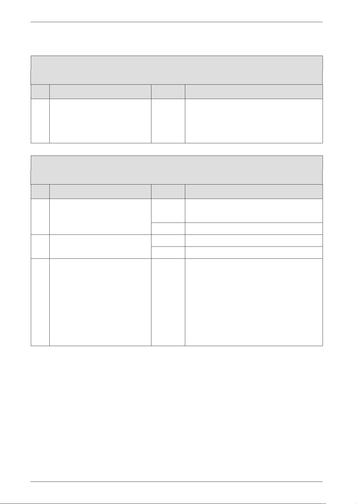
Failure identification procedure
Condensation in the flue pipe
Check Action
1. Is diaphragm in mixer unit fitted correctly (see installation instructions)?
B Open mixer unit (29).
B Fit diaphragm as per installation instructions or
replace.
B Close mixer unit.
B Check diaphragm for correct ori-
entation, soiling and splitting.
3.4.2 Programmer faults
Set room temperature not reached (TR 2 and TR 212 E)
Check Action
1. Thermostatic valve(s) set too low? yes: B Turn up thermostatic valve(s).
↓2.
no: ↓2.
2. CH flow temperature control on
yes: B Turn up CH flow temperature control.
boiler set too low?
no: ↓3.
3. Air in the heating system. B Power OFF the appliance.
B Check appliance and system for water leaks and
repair as necessary.
B Top up system.
B Select Service Function 7.3 .
Select 1 (on, automatically deactivated) and confirm.
B Vent appliance.
B Vent radiators.
B Turn ON the appliance.
48
7 181 465 346 GB (03.02)
Page 93
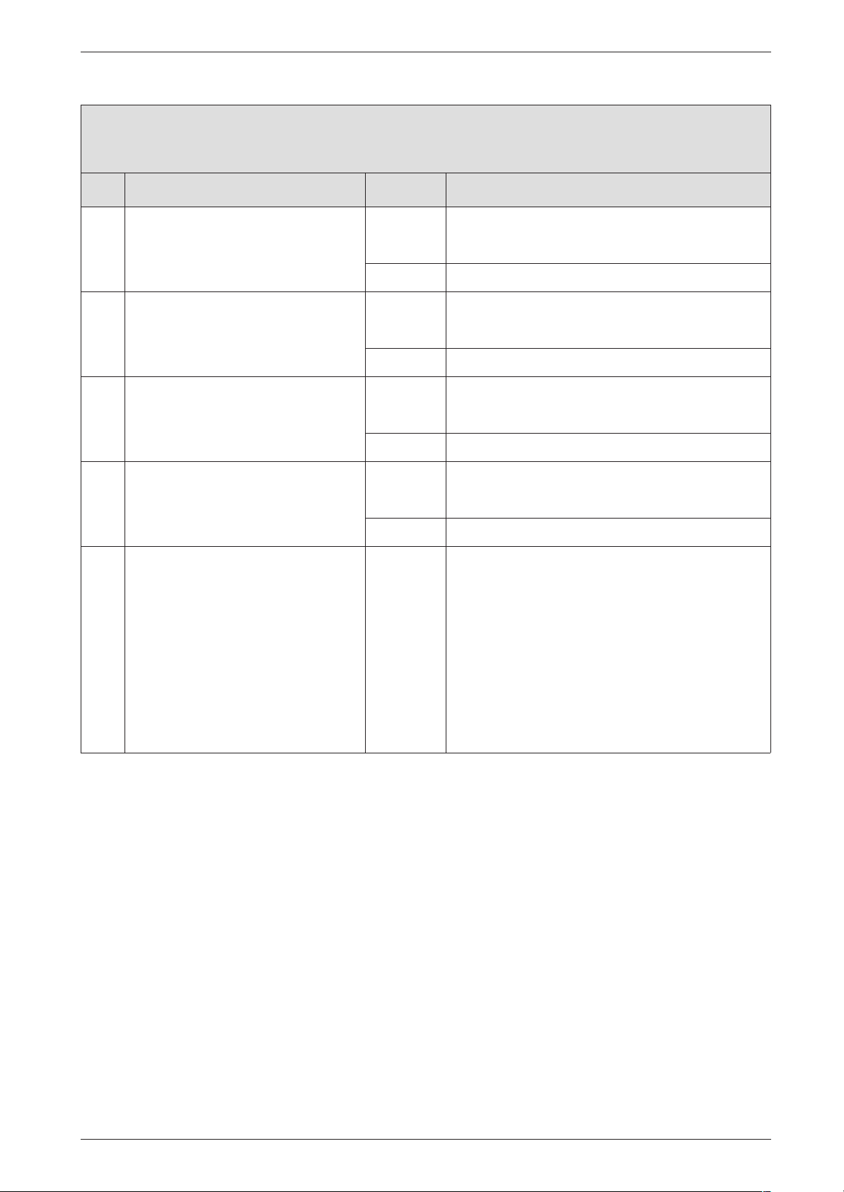
Failure identification procedure
Set room temperature not reached (TA 211 E und DT 2)
Check Action
1. Thermostatic valve(s) set too low? yes: B Turn up thermostatic valve(s).
↓2.
no: ↓2.
2. Heating characteristic set too low? yes: B Correct heating characteristic.
↓3.
no: ↓3.
3. CH flow temperature control on
yes: B Turn up CH flow temperature control.
boiler set too low?
↓4.
no: ↓4.
4. Is heat store temperature unreacha-
yes: B Turn up CH flow temperature control.
ble (CH flow temperature control set
too low)?
↓5.
no: ↓5.
5. Air in the heating system. B Power OFF the appliance.
B Check appliance and system for water leaks and
repair as necessary.
B Top up system.
B Select Service Function 7.3 .
Select 1 (on, automatically deactivated) and confirm.
B Vent appliance
B Vent radiators.
B Turn ON the appliance.
7 181 465 346 GB (03.02)
49
Page 94
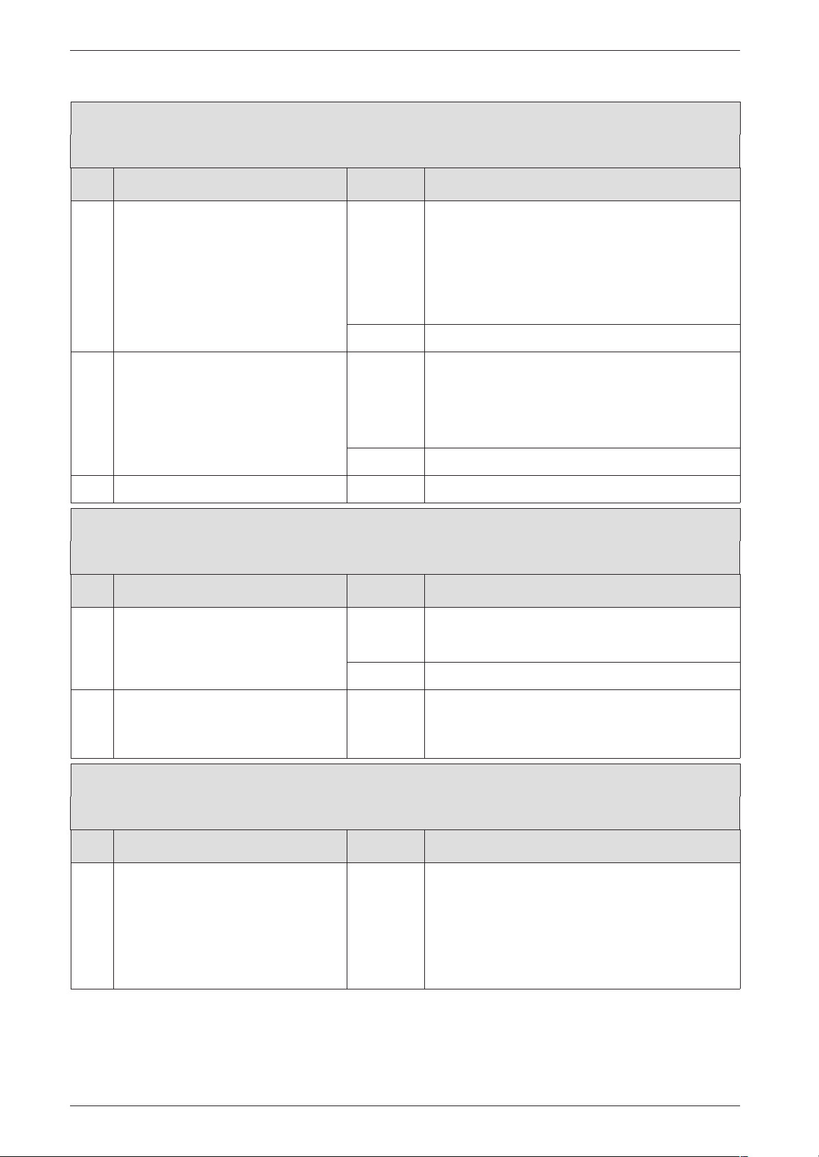
Failure identification procedure
Set room temperature exceeded by large amount
Check Action
1. Do radiators get too hot? yes: TR 2:
B Decrease setting of “Heating” control
TA 211 E:
B Correct heating characteristic.
↓2.
no: ↓2.
2. Bad choice of location for programmer, e.g. outside wall, near window,
in draught, on hollow wall, etc.
yes: B Select better installation location.
-or-
B Fit external room thermostat.
↓3.
no: ↓3.
3. B Turn down thermostatic valve(s).
Excessive fluctuations in room temperature (TA 211 E)
Check Action
1. Periodic effect of external heat on
yes: B Eliminate external heat sources if possible.
room, e.g. from sunshine, lighting, TV,
separate stove, fire, etc.
↓2.
no: ↓2.
2. Bad choice of location for programmer, e.g. outside wall, near window,
in draught, on hollow wall, etc.
B Select better installation location.
-or-
B Fit external room thermostat.
Room temperature too high in Economy mode
Check Action
Building retains heat well yes: B Set economy temperature lower .
50
or
B Set to Frost Protection instead of Economy.
or
B Set start time for Frost protection/Economy
earlier.
7 181 465 346 GB (03.02)
Page 95
Temperature rises instead of falling
Check Action
Timer clock (DT 2) incorrectly set B Check setting and correct as necessary.
Incorrect or no modulation
Check Action
Programmer incorrectly wired B Check wiring against wiring diagram and correct
Failure identification procedure
as necessary.
7 181 465 346 GB (03.02)
51
Page 96
Appendix
4 Appendix
4.1 NTC values
4.1.1 Outside temperature sensor
Outside temperature
(˚C)
Measurement
tolerance ±±±±10% Resistance (ΩΩΩΩ)
-20 2 392
-16 2 088
-12 1 811
-8 1 562
-4 1 342
0 1 149
4 984
8 842
10 781
15 642
20 528
25 436
Table 11
4.1.2 CH flow NTC sensor, heat store NTC sensor, constant hot water NTC sensor and
hot water NTC sensor
Temperature (˚C)
Measurement
tolerance ±±±±10% Resistance (ΩΩΩΩ)
20 14 772
25 11 981
30 9 786
35 8 047
40 6 653
45 5 523
50 4 608
55 3 856
60 3 243
65 2 744
70 2 332
75 1 990
80 1 704
85 1 464
90 1 262
95 1 093
100 950
Table 12
52
7 181 465 346 GB (03.02)
Page 97
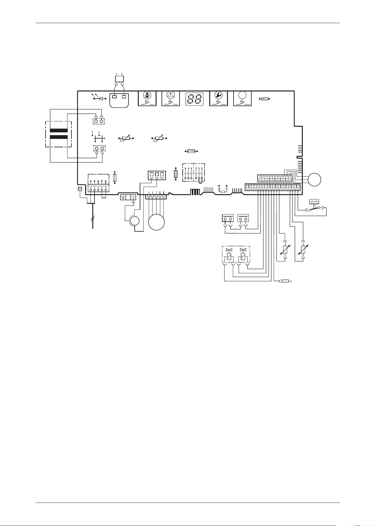
4.2 Electronic schemes
364
4.1
33
o - orange g - green bl - black r - red p - purple
365
61
317
366
367
ECO
363
Appendix
25 V
153
230V/AC
135
302
230 V
328
L
Ns
NLs
136
151
LR
328.1
M
mains supply
4.1 Ignition transformer
6 Heat exchanger overheat cut-out
6.1 Flue gas NTC sensor
6.3 Hot water sensor
18 Central heating pump
32 Flame sensing electrode
33 Spark electrodes
36 Temperature sensor in CH flow
52 Safety gas valve 1
52.1 Safety gas valve 2
56 CE 428 gas valve
61 Reset button
84 Motor (ZWB/ZB)
96 Microswitch, water switch (ZWB)
135 Main power switch
136 Heating outlet temperature potentiometer
151 Fuse T 2,5 A, 230 V AC
153 Transformer
161 Bridge
226 Fan
300 Code key
302 Ground electrical connection
310 Sanitary outlet temperature potentiometer
312 Fuse T 1,6 A, 24 V DC
313 Fuse T 0,5 A, 5 V DC
314 Strip connector for TA 211 E fitted programmer
315 Terminal block for programmer
317 Digital display
318 Internal programmable clock connection
328 230 V AC connection
18
310
M
226
313
312
315
89
1247
300
161
314
9
52
328.1 Bridge
363 Flame presence led
364 Electrical power led (0/I)
365 Chimney cleaner button
366 Technique service button
367 ECO button
6
52.1
56
318
84
p
p
M
p
96
g
g
o
r
r
bl
bl
bl
bl
o
o
36
32
bl
6 720 610 576-08.2O
o
6.1
7 181 465 346 GB (03.02)
53
Page 98
Appendix
4.3 List of most important replacement parts
Component Order no. Remarks
Switchbox
PCB control
board
Transformer 8 747 201 358
Ignition lead 8 714 401 999
20-pin connector lead assembly
20-pin connector lead assembly
Fuse 1 904 552 730 T 0,5 A
Fuse 1 904 552 740 T 1,6 A
Fuse 1 904 521 342 T 2,5 A
Set of fuses 8 744 503 010
Switchbox kpl. 8 717 207 514 with DT 2
8 748 300 385
8 714 402 087 ZB...
8 714 402 086 ZWB...
Component Order no. Remarks
Temperature
sensor, CH flow
Electrode
assembly
Gas valve
Gas valve 8 747 003 516 CE 427
Other components
Fan 8 717 204 343
Gas supply pipe 8 710 725 500
Plate-type heat
exchanger
Overflow trap 8 710 725 328
Diaphragm in the
mixer unit
Table 13
8 714 500 087 NTC
8 718 107 077
8 715 406 651 ZWB...
8 715 505 801
Switchbox kpl. 8 717 207 513 without DT 2
Code plug included in
Conversion kit
G20 -> G31
Conversion kit
G31 -> G20
Conversion kit
G20 -> G31
Conversion kit
G31 -> G20
Conversion kit
G20 -> G31
Conversion kit
G31 -> G20
Conversion kit
G20 -> G31
Conversion kit
G31 -> G20
7 710 149 048 ZWB
7/11-29 A
7 710 239 084 ZWB
7/11-29 A
7 710 149 049 ZB
7/11-28 A
7 710 239 085 ZB
7/11-28 A
7 710 149 044 ZWB
7/11-27 A
7 710 239 080 ZWB
7/11-27 A
7 710 149 045 ZB
7/11-27 A
7 710 239 081 ZB
7/11-27 A
Heat exchanger
Temperature
limiter
Table 13
54
8 729 000 144 110˚C
7 181 465 346 GB (03.02)
Page 99
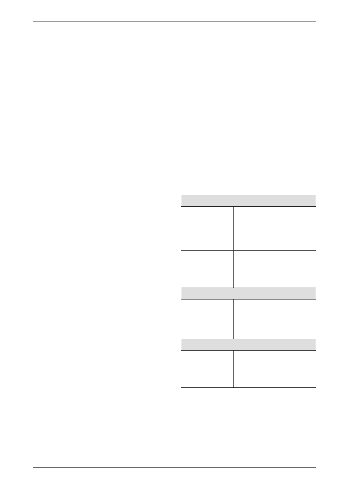
Appendix
4.4 Approved corrosion inhibitors and
anti-freeze fluids for central
heating water
If any system water treatment is required then
only products suitable for use with Aluminium
shall be used i.e Fernox- Copal or Superconcentrate or Sentinal X100, in accordance with the
manufacturers instructions. The use of any other
substances will invalidate the guarantee. The pH
value of the system water must be less than 8 or
the appliance guarantee will be invalidated.
4.4.1 Frost protection
B Add a suitable anti-freeze fluid to the water in the
central heating system.
Suitable products are available from Betz-Dearborn
Tel.: 0151 4209563, Fernox Tel.: 01799 550811
and Salamander Tel.: 0121 378 0952.
4.4.2 Sealing agents
B In our experience, the addition of sealing agents to
the water in the central heating system can cause
problems (deposits in the heat exchanger). For that
reason we advise against their use.
4.5 Summary of BDH Information
Sheet on Identifying Corrosion by
CFCs
The presence of halogenated hydrocarbons in the combustion air causes surface corrosion on affected metals. Particularly susceptible is the combustion chamber
and the heat exchanger surfaces (including stainless
steel) as well as the metal components in the flue
socket, flue pipe connections and in the chimney.
The halogen compounds present in the combustion air
produce highly corrosive hydrochloric acid in the flame
and in some cases - depending on the precise composition of the combustion air - hydrofluoric acid, both of
which accumulate in the boiler and remain active over
long periods.
In order to limit the damage, the source of the air contamination must be located and sealed off. If this is not
possible, the combustion air must be drawn from an
alternative clean source.
Halogens can occur in the following locations:
Commercial and industrial sources
Dry cleaners Trichloroethylene, tetrachlo-
roethylene, fluorinated hydrocarbons
Degreasing baths Perchloroethylene, trichlo-
roethylene, methyl chloroform
Printers Trichloroethylene
Hairdressers Aerosol spray propellants,
hydrocarbons containing fluorine and chlorine (freons)
Sources in the home
Cleaning and
degreasing
agents
Home workshops
Solvents and thinners
Spray cans Chlorofluorohydrocarbons
Table 14
Perchloroethylene, methyl
chloroform, trichloroethylene,
methylene chloride, carbon
tetrachloride, hydrochloric
acid
Various chlorinated hydrocarbons
(freons)
7 181 465 346 GB (03.02)
55
Page 100

 Loading...