

Benchmark BoilerMate BMA 125 OV, BoilerMate OV, BoilerMate BMA 185 OV, BoilerMate BMA 145 OV, BoilerMate BMA 215 OV Design, Installation And Servicing Instructions
...Page 1
A - C L A S S
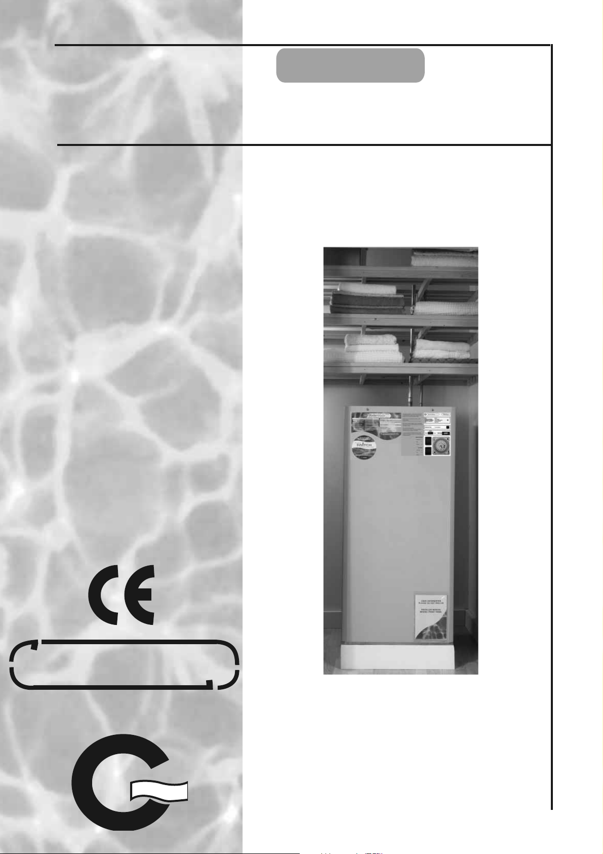
BoilerMate OV
DESIGN, INSTALLATION AND
SERVICING INSTRUCTIONS
Gas Council Approved Reference Numbers
89-317-09 / BMA 125 OV
89-317-10 / BMA 145 OV
89-317-11 / BMA 185 OV
89-317-12 / BMA 215 OV
89-317-13 / BMA 225 OV
TM
benchmark
The code of practice for the installation,
commissioning & servicing of central heating systems
AN OPEN VENTED CENTRAL HEATING
AND MAINS PRESSURE HOT WATER SUPPLY
SYSTEM INCORPORATING
A THERMAL STORE
ALL MODELS COMPLY WITH THE
WATER HEATER MANUFACTURERS
SPECIFICATION FOR INTEGRATED THERMAL
STORES
ISSUE 8: 06-08
Page 2
C ONTENT S
ISSUE 8: 06-08
Section Page
1.0 DESIGN
1.1 Introduction 3
1.2 Technical Data 5
1.3 System Details 11
2.0 INSTALLATION
2.1 Site Requirements 19
2.2 Installation 20
2.3 Commissioning 30
3.0 SERVICING
TM
benchmark
The code of practice for the installation,
commissioning & servicing of central heating systems
Building Regulations and Benchmark Commissioning
The Building Regulations (England & Wales) require that the installation of a
heating appliance be notifi ed to the relevant Local Authority Building Control
Department. From 1st April 2005 this can be achieved via a Competent Person
Self Certifi cation Scheme as an option to notifying the Local Authority directly.
Similar arrangements will follow for Scotland and will apply in Northern Ireland
from 1st January 06.
CORGI operates a Self Certifi cation Scheme for gas heating appliances.
These arrangements represent a change from the situation whereby compliance
with the Building Regulations was accepted if the Benchmark Logbook was
completed and this was then left on site with the customer).
With the introduction of a self certifi cation scheme, the Benchmark Logbook is
being replaced by a similar document in the form of a commissioning check list
and a service interval record is included with all gas appliance manuals. However ,
the relevant Benchmark Logbook is still being included with all T hermal Storage
products and unvented cylinders.
Gledhill fully supports the Benchmark aims to improve the standards of installation
and commissioning of central heating systems in the UK and to encourage the
regular servicing of all central heating systems to ensure safety and effi ciency.
3.1 Annual Servicing 34
3.2 Changing Components 34
3.3 Short Parts List 35
3.4 Fault Finding 36
Appendix A 37
Appendix B 38
Appendix C 41
Appendix D 42
Terms & Conditions 43
The Gledhill BoilerMate range is a WBS
listed product and complies with the WMA
Specifi cation for integrated thermal storage
products. The principle was developed in
conjunction with British Gas. This product
is manufactured under an ISO 9001:2000
Quality System audited by BSI.
Patents Pending
The Gledhill Group’s fi rst priority is to give a
high quality service to our customers.
Building Regulations require that the heating installation should comply with
the manufacturer’s instructions. It is therefore important that the commissioning
check list is completed by the competent installer . This check list only applies to
installations in dwellings or some related structures.
Quality is built into every Gledhill product
and we hope you get satisfactory service
from Gledhill.
If not please let us know.
Page 2
Page 3
These instructions should be read in
conjunction with the Installation and Servicing Instructions issued by the
manufacturers of the heat source e.g. the boiler used.
Any water distribution and central heating installation must comply with
the relevant recommendations of the current version of the Regulations
and British Standards listed below:-
Gas Safety Regulations
Building Regulations
I.E.E. Requirements for Electrical Installations
Water Regulations
British Standards
BS6798, BS5449, BS5546, BS5440:1, BS5440:2, CP331:3, BS6700, BS5258,
BS7593 and BS7671.
A suitably competent person as stated in the Gas Safety Regulations must
install the BoilerMate and carry out any subsequent maintenance/repairs.
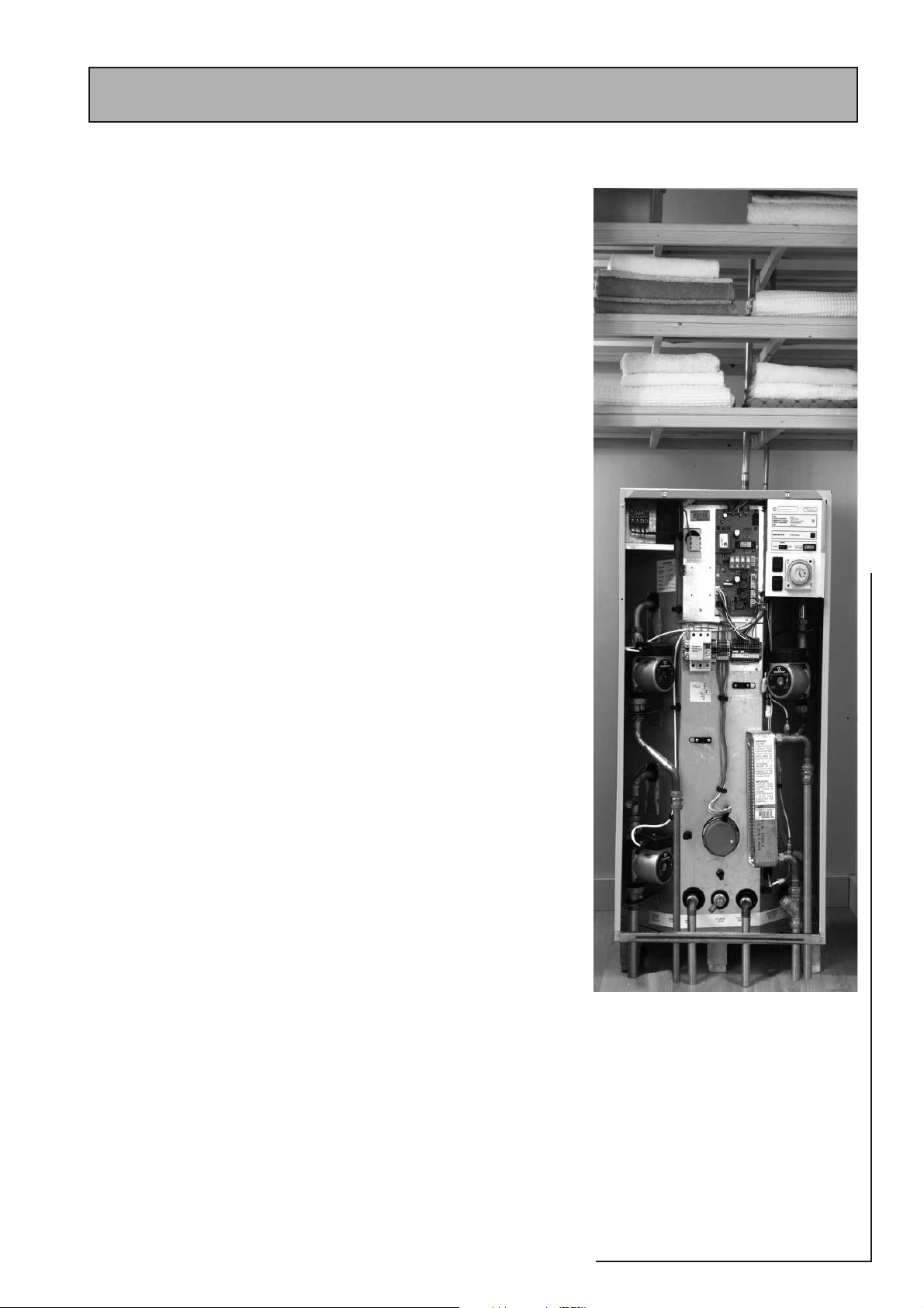
In fact the front panel is secured by 2 screws and should only be removed
by a competent trades person. The manufacturer’s notes must not be
taken as overriding statutory obligations.
1.0 DESIGN
1.1 INTRODUCTION
The BoilerMate A-Class is only suitable for use with an open vented central
heating system.
The BoilerMate A-Class is not covered by section G3 of the current Building
Regulations and is therefore not notifi able to Building Control.
The BoilerMate A-Class OV is not intended for use by persons (including
children) with reduced physical, sensory or mental capabilities, or lack of
experience or knowledge, unless they have been given supervision or
instruction concerning use of the appliance by a person responsible for
their safety.
Children should be supervised to ensure that they do not play with the
appliance.
The information in this manual is provided to assist generally in the selection
of equipment. The responsibility for the selection and specifi cation of the
equipment must however remain that of the customer and any Designers
or Consultants concerned with the design and installation.
Please Note: We do not therefore accept any responsibility for matters of
design, selection or specifi cation or for the effectiveness of an installation
containing one of our products unless we have been specifi cally requested
to do so.
All goods are sold subject to our Conditions of Sale, which are set out
at the rear of this manual.
In the interest of continuously improving the BoilerMate range, Gledhill
Water Storage Ltd reserve the right to modify the product without notice,
and in these circumstances this document, which is accurate at the time
of printing, should be disregarded. It will however be updated as soon
as possible after the change has occurred.
OV
A-CLASS
Page 3
BOILERMATE
Page 4
-AINSCOLD
WATER
2EMOTE
&%TANK
7ARNINGOVERFLOW
PIPE
1.0 DESIGN
fi tted by the installer at a suitable point in the
cold water supply to the appliance.
If scale should ever become a problem the plate
heat exchanger is easily isolated and quickly
replaced with a service exchange unit which can
be obtained at a nominal cost from Gledhill.
/PEN6ENT
0RIMARYFLOW
0RIMARY
RETURN
"OILER
"-
!#LASS
&ULLBOREAUTOMATICBYPASSVALVE./42%15)2%$
UNLESSTHEHEATINGSYSTEMINCORPORATES
MECHANICALTHERMOSTATICCONTROLVALVESEG
426gSTOALLRADIATORSORPORTZONEVALVES
#OLDFEED
1.1 INTRODUCTION
Description
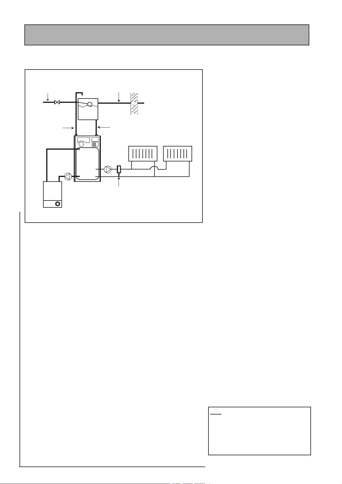
The BoilerMate A-Class OV shown schematically above is designed to provide improved
space heating and mains pressure hot water when coupled to any remotely sited
condensing or non condensing boiler.
The principle of a BoilerMate A-Class is to separate the heat generator e.g. a boiler
from heat emitters (radiators) by a thermal store, which evens out the fl uctuating
demands for heating and hot water.
Because this product does not require a safety discharge from a temperature and
pressure relief valve, any installations will be easy to incorporate into the building and
will not suffer from the problems associated with using PVCu soil stacks to take the
discharge from unvented cylinders.
An important feature of this concept is that hot water can be supplied directly from
the mains at conventional fl ow rates without the need for temperature and pressure
relief safety valves or expansion vessels. This is achieved by passing the mains water
through a plate heat exchanger . T he outlet temperature of the domestic hot water is
maintained by a printed circuit board (A.C.B.), which controls the speed of the pump
circulating the primary water from the store through the plate heat exchanger.
The Building Regulations L1A: New dwellings/L1B: Existing dwellings and the
requirements set out in the Domestic Heating Compliance Guide specify that “where
the mains water hardness exceeds 200ppm provision should be made to treat the
feed water to water heaters and the hot water circuit of combination boilers to reduce
the rate of accumulation of lime scale”.
To comply with this r equirement the hardness of the mains water should be checked
by the installer and if necessary the optional factory fi tted electronic in-line scale
inhibitor should be specifi ed at the time of order for hardness levels between 200
and 300 ppm (mg/l).
Where the water is very hard ie 300ppm (mg/l) and above the optional polyphosphate
type, inhibitor should be specifi ed at the time of order. However, this will need to be
The A.C.B. also incorporates the facility to
operate the heating pump for a few seconds
every few days when the heating is not being
used (to reduce the likelihood of the pumps
sticking) as well as providing a boiler pump
overrun facility.
Any automatic boiler designed to operate on an
0
82
C fl ow and a 710C return up to a maximum
of 35kW can be linked to any suitable model of
BoilerMate A-Class and the deciding factor is the
space heating and the hot water requirements
of a dwelling. See Sec tion 1.2 Technical Data
for further details.
The BoilerMate A-Class OV is supplied complete
with ‘Switch ’ which will provide a 6kW electrical
emergency backup in case of failure of the main
heat source. See section 1.3 System Details for
further information.
The heat losses from thermal stores should not
be directly compared with heat losses from
unvented or vented cylinders because they are
treated differently in SAP. The SAP calculator
takes account of the type of store and various
correction factors are included to refl ect the
different ways that the hot water and heating
operates.
For further information please request a copy
of the SAP 2005 Data Sheet which provides
the information required to produce SAP
calculations for all Gledhill Thermal Storage
products.
Gledhill are part of the ‘Benchmark’ scheme and
a separate commissioning/service log book is
included with the product.
A 15mm connection is provided on the primary
return on all units to allow for the provision
of a pumped summer use towel rail circuit if
required (see page 16 for further details)
Note
The BoilerMate OV is a SYSTEM appliance
and only requires a basic boiler. If a system
boiler is chosen this will present wiring/
operational diffi culties as well as incurring
extra costs.
Page 4
Page 5
1.0 DESIGN
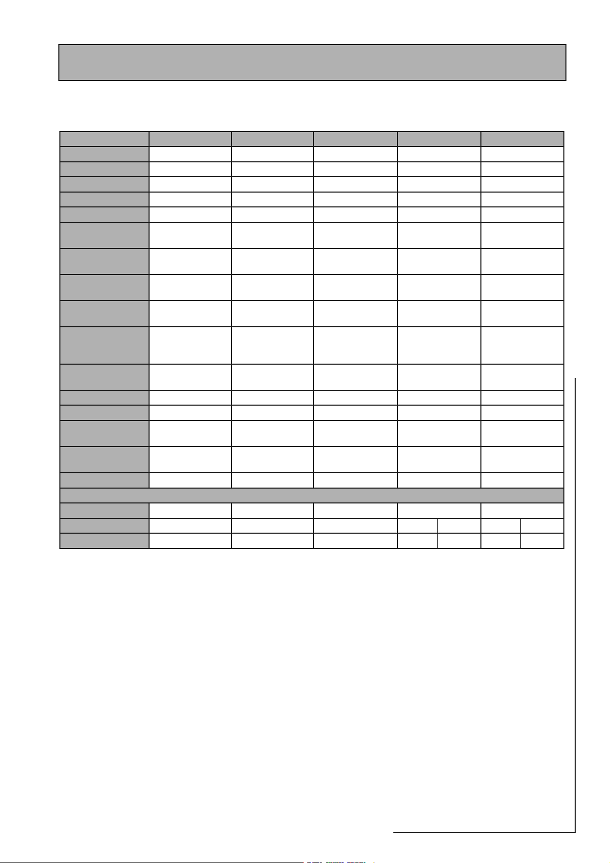
1.2 TECHNICAL DAT A
Model BMA 125 OV BMA 145 OV BMA 185 OV BMA 215 OV BMA 225 OV
Weight (empty) 45 47 50 51 56
Weight (full) 177 187 197 215 244
DHW Pump
Heating Pump
Boiler Pump
Primary/heating
pipe connections
MCW & DHW pipe
connections
Cold feed/expansion
connection
Safety open vent
connection
Primary return
(for summer use
bathroom towel rail)
Maximum summer
towel rail load
Drain connection R ½” R ½” R ½” R ½” R ½”
Maximum Head 6 meters 6 meters 6 meters 6 meters 6 meters
Hot water fl ow rate
(l/m) up to
Max heating system
size
‘Switch’ 6 kW 6 kW 6 kW 6 kW 6 kW
Typical Dwelling Types
Bedrooms 1-3 2-3 2-4 3-5 4-6
Bathrooms 1 1 2 1 2 1 2
En-suite shower 1 2 1 4 2 4 3
Grundfos UPR 15/50 Grundfos UPR 15/50 Grundfos UPR 15/50 Grundfos UPR 15/50 Grundfos UPR 15/50
Grundfos UPS 15/50 Grundfos UPS 15/50 Grundfos UPS 15/50 Grundfos UPS 15/60 Grundfos UPS 15/60
Grundfos UPR 15/50 Grundfos UPR 15/50 Grundfos UPR 15/50 Grundfos UPR 15/60 Grundfos UPR 15/60
22mm 22mm 22mm 28mm 28mm
22mm 22mm 22mm 22mm 22mm
22mm 22mm 22mm 22mm 22mm
22mm 22mm 22mm 22mm 22mm
15mm 15mm 15mm 15mm 15mm
0.15kW 0.75kW 1.00kW 1.25 kW 1.5 kW
35 35 35 35 35
12 kW 17 kW 20 kW 25 kW 30 kW
Notes:-
1. The BoilerMate 225 appliance is suitable for use in large properties because it produces the same ‘ peak hour output’ as a typical 350400 litre unvented cylinder . For properties requiring the BMA 225 the incoming main should be a minimum of 32mm MDPE with
a pressure of not less than 2 bar dynamic and an adequate fl ow in line with the pipe sizing calculations. In many cases , properties
of this size will benefi t from having 2 smaller sized appliances located adjacent to the areas of peak hot water use. This will allow
2 heating zones to be provided and remove the need to provide trace heating on the hot water system.
2. A plastic feed and expansion cistern will be supplied separately including ballvalve, fl oat and overfl ow fi tting.
3. The fl ow rates are based on a 35°C temperature rise and assume normal pressure and adequate fl ow to the appliance. The actual
fl ow rate from the appliance is automatically regulated to a maximum of 28 litres/min.
4. Unit is supplied on a 100mm high installation base.
5. The domestic hot water outlet temperature is automatically regulated to approximat ely 52°C at the bath fl ow rate of 18 litres/min
recommended by BS 6700. The temperature is not user adjustable.
Page 5
OV
A-CLASS
BOILERMATE
Page 6
10
1.0 DESIGN
1.2 TECHNICAL DAT A
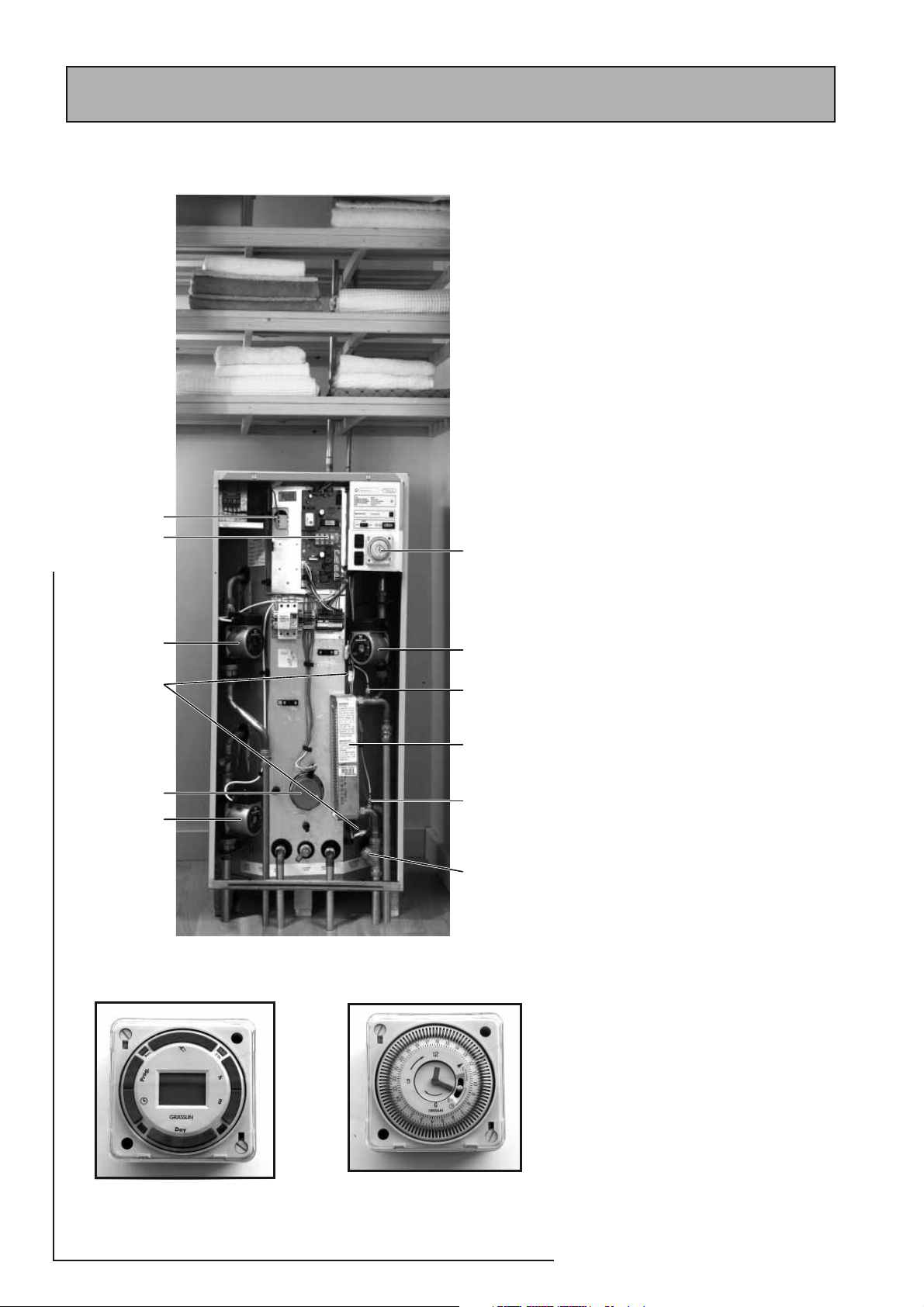
Standard Equipment
The standard confi guration of the BoilerMate
A-Class OV is shown opposite. The Appliance
Control Board (A.C.B.), mounted inside the
appliance, controls the operation of the
complete system. The A.C.B. is pre-wired to a
terminal strip where all electrical connections
terminate. It is supplied with the following
factory fi tted equipment:-
1. Boiler pump
2. Domestic hot water primary (plate
heat exchanger) pump - modulating
3. Space heating pump
4. Appliance control board (A.C.B.)
5. Electro-mechanical clock for hot water and
space heating time control.
6. Plate heat exchanger
7. DHW temperature sensor
4
5
3
9
2
7
8. Cold water inlet sensor
9. Store temperature sensors
10. Overheat sensor
11. Y type strainer/fl ow regulator
12. A feed and expansion cistern complete
with ballvalve, overflow fitting and cold
feed/open vent pipework assembly is
supplied separately.
13. ‘Switch’ elements (2 x 3 kW)
Optional Equipment
13
6
8
1
11
* A seven day digital clock/programmer
to control the space heating (in
conjunction with a room thermostat)
* A no clock/multi-zone option.
* Hot and cold water manifolds for use
with plastic pipework.
* Modulating type (UPR) pump for the
space heating circuit.
* Electronic scale inhibitor for mains water
services
200ppm(mg/l) - fi tted in the appliance.
* Polyphosphate scale and corrosion
inhibitor for mains water services with
hardness levels above 300 ppm (mg/l)
for fi tting on site by the installer.
with hardness levels above
Digital clock programmer
Electro-mechanical clock
programmer
Page 6
Page 7
MM
&%#ISTERN
1.0 DESIGN
1.2 TECHNICAL DAT A
-INMAINTENANCE
ACCESSTOCOMPLYWITH
THE7ATER2EGULATIONS
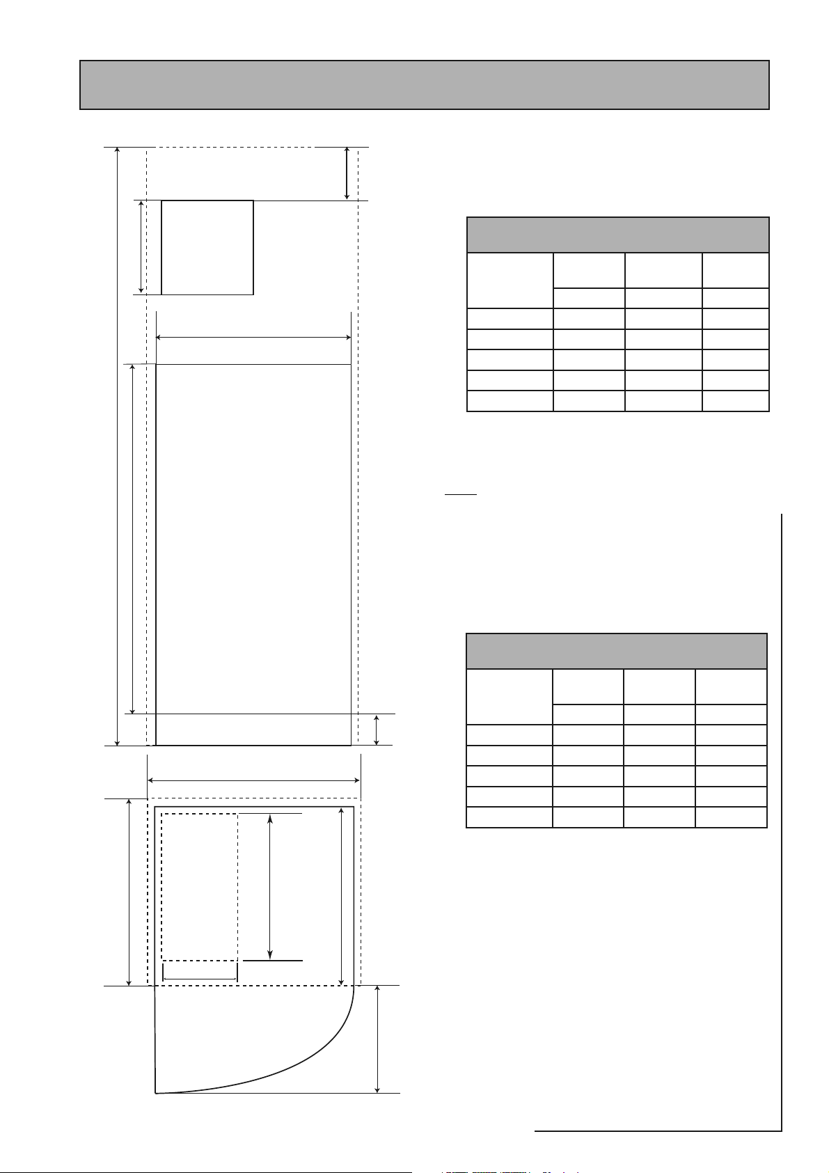
MM
APPLIANCE DIMENSIONS
MODEL Height Width Depth
ABC
BMA 125 OV 960mm 530mm 595mm
"
BMA 145 OV 1000mm 530mm 595mm
BMA 185 OV 1040mm 530mm 595mm
BMA 215 OV 1145mm 530mm 595mm
BMA 225 OV 1300mm 530mm 595mm
Note: The Appliance dimensions above do not allow for
the100mm high installation base
!
$
&
"OILER-ATE!#LASS
&%#ISTERN
PLAN
%
MM
#50"/!2$
The following table of minimum cupboard dimensions only
allow the minimum space required for the appliance (including
the F & E cistern) and any extra space required for shelving etc
in the case of airing cupboards etc must be added.
MINIMUM CUPBOARD DIMENSIONS
MODEL Height Width Depth
DEF
MM
BMA 125 OV 1710mm 630mm 600mm
BMA 145 OV 1750mm 630mm 600mm
BMA 185 OV 1790mm 630mm 600mm
BMA 215 OV 1895mm 630mm 600mm
BMA 225 OV 2050mm 630mm 600mm
#
Note: The above dimensions are based on the Appliance and
the F & E cistern being in the same cupboard.
OV
MM
MMMINCLEAROPENINGIF
LOCATEDDIRECTLYINFRONTOFTHE
APPLIANCE
-AINTENANCE
ACCESS
MM
If a Multi-Zone appliance is used an additional 150mm must
be added to the above heights to accomodate the space
required for the zone equipment.
Page 7
A-CLASS
BOILERMATE
Page 8
530
1.0 DESIGN
1.2 TECHNICAL DATA
BOILER RETURN 475
TOWEL RAIL RETURN 560
CENTRAL HEATING FLOW 560
120
560
CENTRAL HEATING RETURN
OPEN VENT
22
COLD FEED
55
15
BOILER FLOW
145
205
550
DOMESTIC HOT WATER
COLD FEED
C
L
65
95
155
220
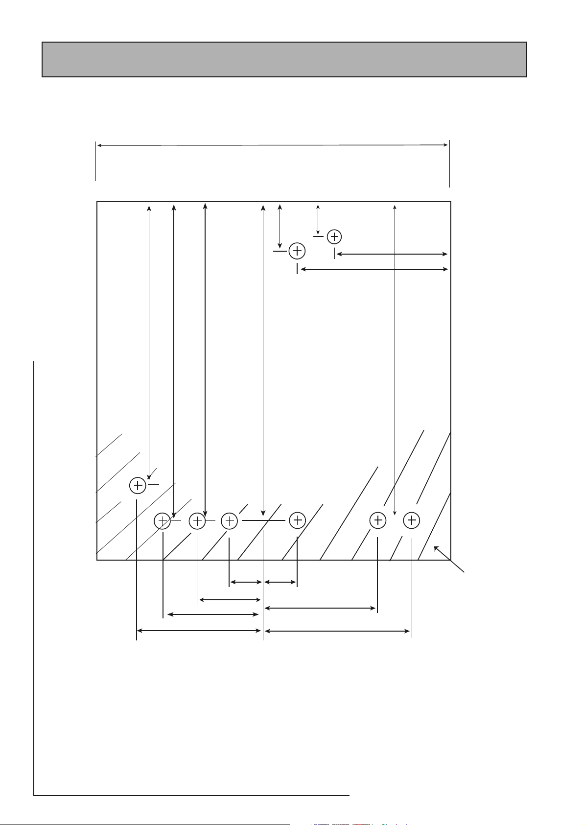
All dimensions in mm - to centre line of pipework
The BoilerMate A-Class units are supplied on an installation base to allow the pipe runs to
connect to the appliance from any direction. It is easier if all pipes protrude vertically in the
cut out area shown. Compression or push fit connections can be used. All pipe positions
are approximate and subject to a tolerance of +/-20mm in any direction. A 15mm cold
water supply and a 22mm warning/overflow pipe will also be required for the separate
feed and expansion tank.
65
185
220
Page 8
Cut out area
in base
Page 9
1.0 DESIGN
Tank_middle
T_overh_2
T_dhw_in
220_1
220_1
SWL_IN
220_0
220_1
220_PE
.ORMALSTANDBYSTATE
)NDICATESYSTEMSTATUS
0RESS3
3ENSORTEMPERATUREREADING
0RESS3
#ONTROL3ETPOINTREADING
Push button
1.2 TECHNICAL DATA
Appliance Control Board
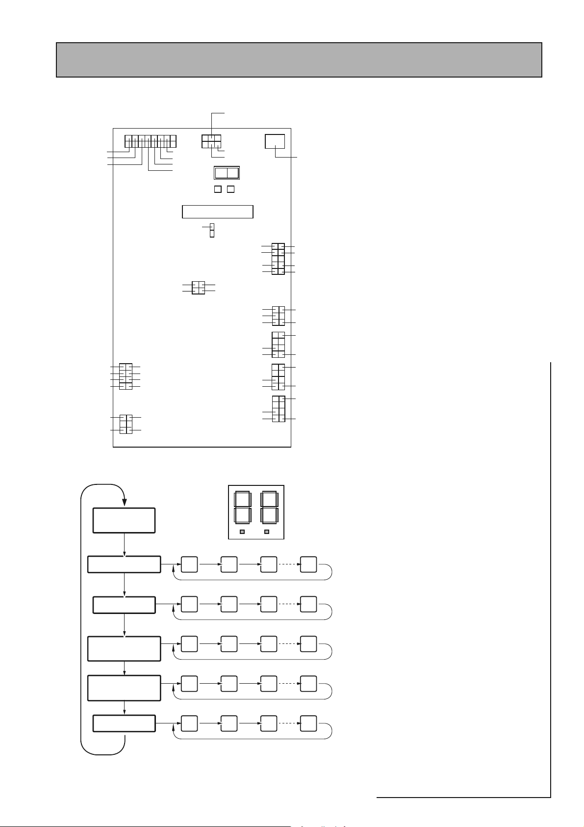
The appliance control board (shown opposite)
has a 2 digit display and 2 push buttons which
are used to check the status of the appliance,
check and set its identity and interrogate it for
the current faults and the fault history.
The 2 digit display is controlled by 2 buttons S1
and S2 The fl ow chart of display modes is shown
below. Generally , each pr ess of button S2 cycles
the display from top to bottom and each press
of button S1 cycles the display functions from
left to right.
The button S2 is also used to reset the appliance
i.e. clear the lockout errors and reset the
appliance. (Note: Appliance resetting can also
be carried out using the push button on the
front panel)
Display in Normal (Standby) Mode
In the standard/normal mode the 2 digit display
indicates the status of the appliance inputs
and outputs by switching on the appropriate
segments of the display - see page 29 for
details.
Appliance Type Selection
The BoilerMate is fi tted with an identity (ID)
resistor which is read by the controller for
comparison with the appliance type (code)
set on the controller. The two must match for
the controller/appliance to function. Therefore
if either the appliance code setting or the ID
resistor is wrong, the appliance will shut down
safely and fl ag the error code until the fault
is rectified. The controller codes and the ID
resistor values for the BoilerMate are 01 and 1K5
respectively. The procedure for checking and
setting the appliance code on the controller is
described below.
• The appliance selection menu (A0 ... A9) on the
controller is hidden. It is only possible to get to
the appliance selection using the reset button
(Left hand, S2) on the main board.
ID_resistor
T_overh_1
Tank_bot
T_dhw_out
FLIP jumper
DIV_OUT_1
220_0
8
16
J31
Reset
button
Main processor
J29
Ext_led_k
Ext_se_1
Enter
button
S2 S1
WD_RECEIVE
VSS
SAFETY
220_1
DIV_OUT_2
220-0
OVERHEAT
220_0
BOIL_HEAT_DEM
J33
CH_P_MOD
CH_P_L CH_P_L
J32
BOILER_P_MOD
BOIL_P_L BOIL_P_N
J34
DHW_P_MOD
DHW_P_L DHW_P_N
J30
J3
PC Connector
SEND_TO_GAS
VSS
GASV_IN
220_0
EL_HEAT_OUT
BOIL_HEAT_DEM
CH_P_PE
BOIL_P_PE
DHW_P_PE
1
J9
9
J28
DHW_ON_IN
CH_ON_IN
220_INPUT
220_0
J5
220_0
220_PE
APPLIANCE CONTROL BOARD
3
3
0RESS3
0RESS3 0RESS3 0RESS3 0RESS3
0RESS3 0RESS3 0RESS3
3 3 3 3
3 3 3 3
0RESS3
&AULTCODE)NDICATION
,OCKOUTS
0RESS3
&AULTCODEINDICATION
"LOCKOUTS
0RESS3
!PPLIANCE4YPE
0RESS3 0RESS3 0RESS3 0RESS3
# # # #&
0RESS3 0RESS3 0RESS3 0RESS3
C C C C&
0RESS3 0RESS3 0RESS3 0RESS3
! ! ! !
$IGIT!#""OARD$ISPLAY&LOW#HART
Page 9
• When going from the show ‘ locking error’ to
show ‘block ing error’ menu (see opposite), do
not release the button but hold it for 10 seconds.
The display will change from ‘ c’ to ‘A ’. At this stage
the push button (S2) can be released.
• The appliance type can now be selected by
using right hand push button, S1, e.g. for this
appliance A01.
Press the reset button, S2, to accept the setting.
If the selected appliance code does not match
with the ID resistor fi tted to the appliance, then,
an error ‘33’ will be displayed.
OV
A-CLASS
BOILERMATE
Page 10
1.0 DESIGN
1.2 TECHNICAL DATA
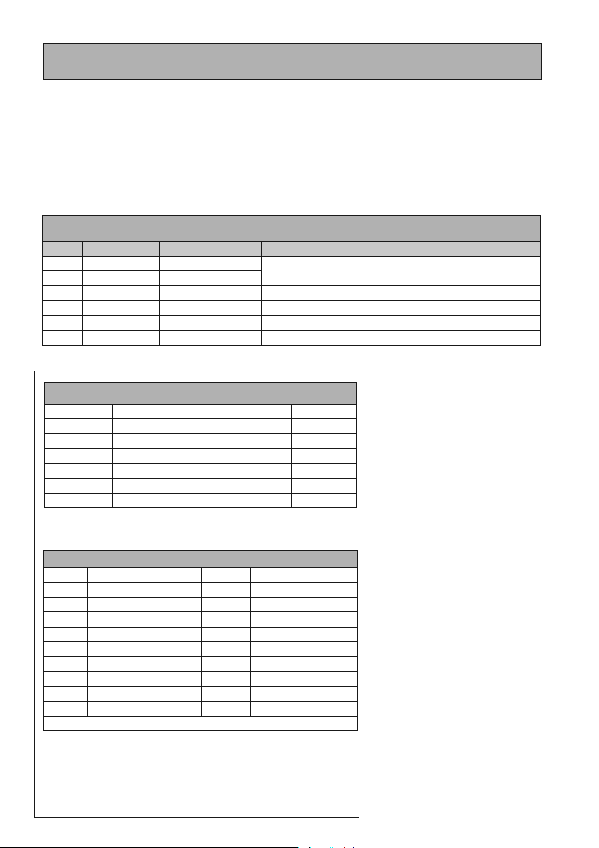
Sensor Tempa ture Readings
Details of the various sensors S1-S6 used in
the BoilerMate A-Class are shown opposite.
The sensor reference i.e. S1 and the actual
temperature at that sensor fl ash alternately on
the display when selected.
Sensors used in BoilerMate A-Class
Sensor Sensor Connector J9 pins Location
S1 T Overheat 1 6 & 14
S2 T Overheat 2 2 & 10
S3 T DHW in 3 & 11 In cold water inlet pipe (Wet i.e. direct)
S4 T DHW out 4 & 12 In hot water outlet pipe (Wet i.e. direct)
S5 T Tank bottom 5 & 13 Bottom of store in dry pocket for store charging
S6 T Tank middle 1 & 9 Middle of store in dry pocket for store charging
Top of store in dry pocket (S1 & S2 are in single housing)
Sensor Control Set Points
Display Sensor Temp
S1 Middle store sensor on 68
S2 Middle store sensor off 77
S3 DHW in 35
S4 DHW out 55
S5 Bottom store sensor on 60
S6 Bottom store sensor off 70
Common Fault Codes
Code Code
10 Overheat error 45 S1 overheat 1 shorted
30 Phase error 48 I.D. resistor shorted
33 Appliance selection 49 S4 sensor shorted
37 S1 overheat 1 open 50 S5 sensor shorted
40 I.D. resistor open 51 S6 sensor shorted
41 S4 sensor open 52 S2 overheat 2 shorted
42 S5 sensor open
43 S6 sensor open
44 S2 overheat 2 open
Any other code displayed should be checked against the full chart
Control Set Points
The sensor control set points are shown
opposite. PLEASE NOTE THAT THE DISPLAY
S1 - S6 IS NOT THE SAME AS THE SENSOR
REFERENCE.
Fault Codes
Fault code locations are numbered C0 - CF
c0 - cF.
and
CO/cO locations hold the latest fault recorded.
A code of FF indicates that the fault location
is empty.
If a sensor is faulty instead of a temperature
it will show E1 if open circuit and E2 if short
circuit.
Page 10
Page 11
1.3 SYSTEM DETAILS
Hot and Cold Water System
General
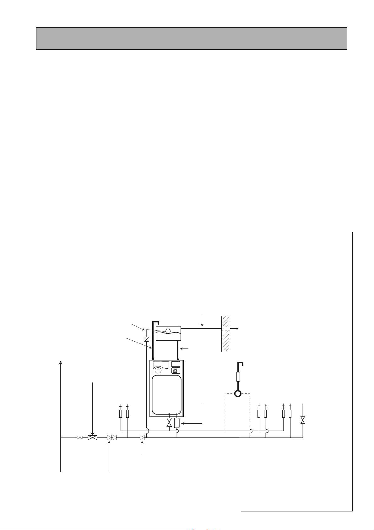
A schematic layout of the hot and cold water services in a typical small dwelling is
shown below. BoilerMate A-Class will operate at mains pressures as low as 1 bar and
as high as 5 bar although the recommended range is 2-3 bar. These pressures are the
minimum dynamic pressures at the cold connection to the BoilerMate A-Class at the
time of the maximum calculated simultaneous demand. If the manifolds (av ailable as
an optional extra) are being used the inlet pressure to the manifold must be a minimum
of 2 bar. Particular consideration should also be given to available pressures in the
case of 3 storey properties. It is also important to check that all other equipment and
components in the hot and cold water system are capable of accepting the mains
pressure available to the property. If the mains pressure can rise above 5 bar or the
maximum working pressure of any item of equipment or component to be fi tted in
the system a pressure limiting (reducing) valve set to 3 bar will be required.
If you encounter a situation where the water pressure is adequate but fl ow rates are
poor please contact our technical helpline for details of an effective solution.
Note: Each BoilerMate A-Class is fi tted with a strainer and fl ow regulator on the cold
mains supply connection. If the supply pressure is less than 2 bar or if the manifolds
(available as an optional extra) are being used or if all taps are provided with fl ow
regulators the fl ow regulator on the cold inlet should be removed.
No check valve or similar device should be fi tted on the cold water supply branch to
the BoilerMate A-Class.
1.0 DESIGN
To comply with this requirement the hardness
of the mains water should be checked by the
installer and if necessary the optional factory
fi tted in-line scale inhibitor should be specifi ed
at the time of order for hardness levels between
200 and 300 ppm (mg/l).
Where the water is very hard ie 300ppm (mg/l)
and above the optional polyphosphate type,
inhibitor should be specifi ed at the time of
order. However, this will need to be fi tted by
the installer at a suitable point in the cold water
supply to the appliance.
If scale should ever become a problem the
plate heat exchanger is easily isolated and
quickly replaced with a service exchange unit
which can be obtained at a nominal cost from
Gledhill.
The hot water fl ow rate from the BoilerMate
A-Class is directly related to the adequacy
of the cold water supply to the dwelling.
This must be capable of providing for those
services, which could be r equired to be supplied
simultaneously, and this maximum demand
should be calculated using procedures defi ned
in BS 6700.
The Building Regulations L1A: New dwellings/L1B: Existing dwellings and the
requirements set out in the Domestic Heating Compliance Guide specify that “where
the mains water hardness exceeds 200ppm provision should be made to treat the feed
water to water heaters and the hot water circuit of combination boilers to reduce the
rate of accumulation of lime scale”.
Warning/overflow
pipe
Cold feed/
expansion
Optional
polyphosphate
scale inhibitor - NOT
REQUIRED
unless the hardness
level exceeds
300ppm (mg/l)
Second
dwelling
Cold mains
supply
Open vent
Pressure limiting valve NOT
REQUIRED at pressures
below 5 bar unless any
components have a lower
maximum working
pressure.
Sink
C
H
F&E Cistern
BM A-Class
a a
'a'
- flow regulator recommended for better
balance of hot and cold water supplies.
Check valve NOT REQUIRED unless
chemical water treatment unit is fitted.
If a water meter is fi tted in the service pipe,
it should have a nominal rating to match the
maximum hot and cold water peak demands
calculated in accordance with BS 6700. This
could be up to 80ltr/min in some properties.
Shower.
Hand
Bath
H C H C C
basin
WC - fitted
with BS1212
ballvalve
a a a a a
S.V.
OV
A-CLASS
M.C.W.S
supply pipe.
Double check valve NOT REQUIRED unless supply
pipe services more than one dwelling.
Typical hot and cold water distribution
BOILERMATE
Page 11
Page 12

1.3 SYSTEM DETAILS
Hot and Cold Water System
Pipe Sizing / Materials
1.0 DESIGN
To achieve even distribution of the available supply of hot and cold water, it is
important in any mains pressure system, that the piping in a dwelling should be
sized in accordance with BS 6700. This is particularly important in a large propert y
with more than one bathroom.
However, the following rule of thumb guide lines should be adequate for most
smaller property types as long as water pressures are within the recommended
range of 2-3 bar.
1. A 15mm copper or equivalent external service may be suffi cient for a small
1bathroom dwelling (depending upon the fl ow rate available), but the minimum
recommended size for new dwellings is 22mm (25mm MDPE). For the BMA 225
model we recommend a 28mm (32mm MDPE) supply pipe.
2. The internal cold feed from the main incoming stop tap to the BoilerMate
should be run in 22mm pipe. The cold main and hot draw-off should also
be run in 22mm as far as the branch to the bath tap.
3. The fi nal branches to the hand basins and sinks should be in 10mm and to
the baths and showers in 15mm. (1 metre minimum)
4. If an ex ternal hose tap is provided this should be branched in 15mm pipework
from the cold pipework as near to the incoming mains as possible.
5. We would recommend that best results for a balanced system are achieved
by fi tting appropriate fl ow regulators to each hot and cold outlet. This is
particularly relevant where the water pressures are above the recommended
water pressure range of 2-3 bar , or the dwelling is 3 store y . Details of suitable
fl ow regulators are provided in Appendix A.
Note: If manifolds (available as an optional extra) are being used suitable fl ow
regulators are automatically provided in the manifold and do not need to be
provided at each outlet - See Appendix B for further details.
All the recommendations with regard to pipework systems in this manual are
generally based on the use of BS/EN Standard copper pipework and fi ttings.
However , we are happy that plastic pipework systems can be used in place of copper
internally as long as the chosen system is recommended for use on domestic hot
and cold water systems by the manufacturer and is installed fully in accordance
with their recommendations.
However , if it is proposed to use a ‘whole body’
or similar shower with a number of high fl ow/
pressure outlets please discuss with the Gledhill
technical department.
The hot water supply to a shower-mixing valve
should be fed wherever practical directly from
the BoilerMate A-Class or be the fi rst drawoff point on the hot circuit. The cold supply
to a shower-mixing valve should wherever
practical be fed directly from the rising mains
via an independent branch. The shower must
incorporate or be fitted with the necessary
check valves to provide back-syphonage
protection in accordance with the Water
Regulations.
The supply of hot and cold mains water directly
to a bidet is permitted provided that it is of the
over-rim fl ushing t ype and that a type ‘A’ air
gap is incorporated.
Hot and Cold Water System.
If the length of the hot water draw off
pipework is excessive the delivery time may
be unacceptable before hot water is available
at the tap, you may wish to c onsider using trace
heating to the hot water pipework such as the
Raychem HWAT system. Please consult Gledhill
Technical Department for further details.
It is important that the cold water pipework
is adequately separated/protected from any
heating/hot water pipework to ensure that
the water remains cold and of drinking water
quality.
It is also essential that if an alternative pipework material/system is chosen the
manufacturer confi rms that the design criteria of the new system is at least equivalent
to the use of BS/EN Standard copper pipework and fi ttings.
Taps/Shower Fittings
Aerated taps are recommended to prevent splashing.
Any type of shower mixing valve can be used as long as both the hot and cold
supplies are mains fed. However, all mains pressure systems are subject to
dynamic changes particularly when other hot and cold taps/showers are opened
and closed, which will cause changes in the water temperature at mixed water
outlets such as showers. For this reason and because these are now no more
expensive than a manual shower we strongly r ecommend the use of thermostatic
showers with this appliance. These must be used in 3 storey properties where
the impact on pressure/temperature of opening another tap in the system is
greater than normal.
The shower head provided must also be suitable for mains pressure supplies.
Page 12
Page 13
1.0 DESIGN
1.3 SYSTEM DETAILS
Heating System
-AINSCOLD
WATER
/PEN6ENT
0RIMARYFLOW
0RIMARY
RETURN
"OILER
7ARNINGOVERFLOW
PIPE
2EMOTE
&%TANK
#OLDFEED
"-
!#LASS
&ULLBOREAUTOMATICBYPASSVALVE./42%15)2%$
UNLESSTHEHEATINGSYSTEMINCORPORATES
MECHANICALTHERMOSTATICCONTROLVALVESEG
426gSTOALLRADIATORSORPORTZONEVALVES
General
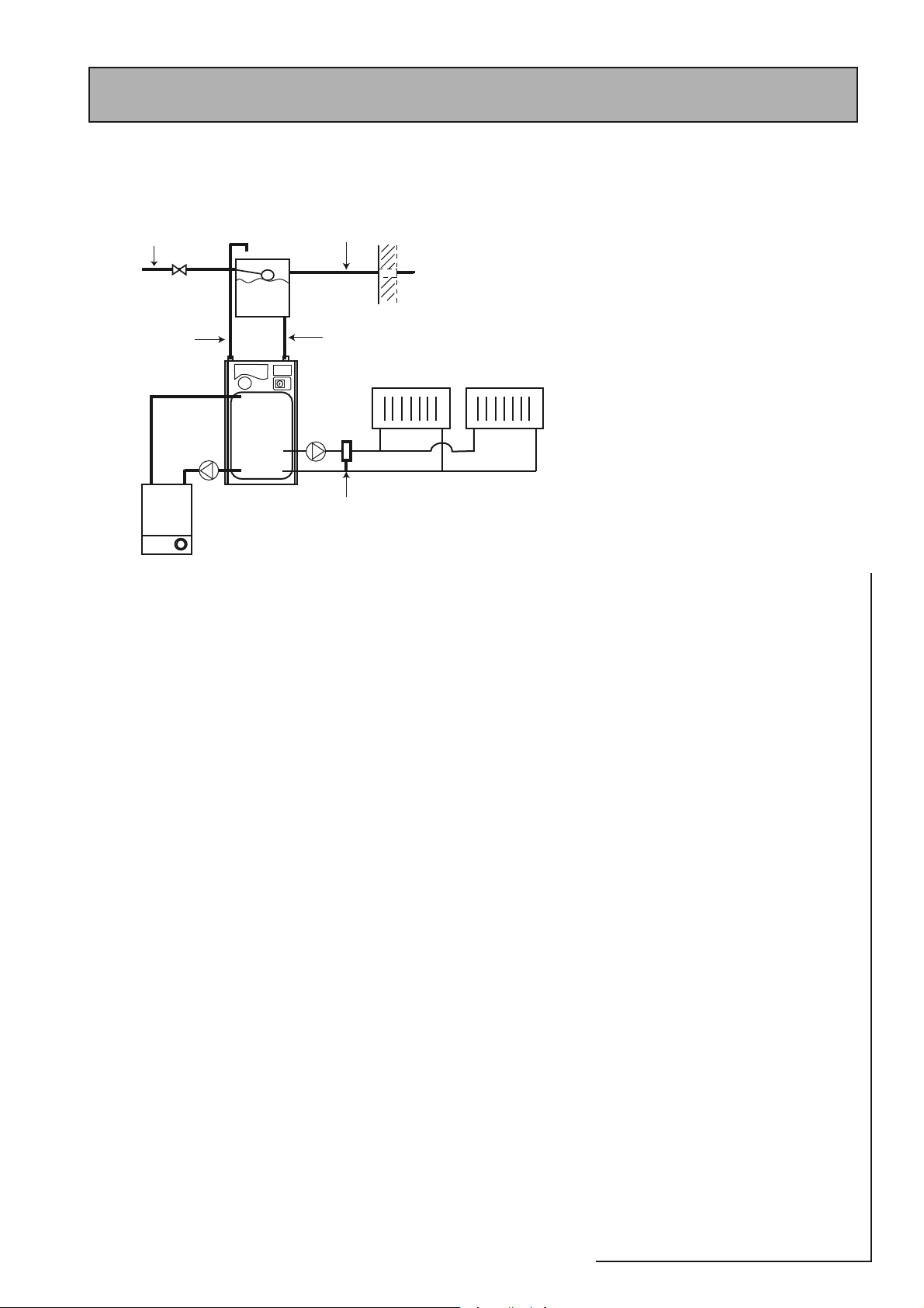
A schematic layout of the heating system in a
typical small dwelling is shown opposite.
The flow and return from the boiler must
always run directly to the BoilerMate A-Class
and the flow should rise continuously to
facilitate venting. The heating circuit is taken
from the BoilerMate A-Class and is piped in the
conventional manner.
The BoilerMate A-Class is only suitable for an
open vented system.
The F & E cistern can be fi tted remotely up to
6 m above the base of the BoilerMate A-Class
i.e. the maximum static pressure in the store
must not exceed 0.6 bar.
If any radiators are located above the level
of the BoilerMate A-Class the system should
be designed so that gravity circulation does
not occur when the heating pump is not
running. To be certain of preventing this it is
recommended that a check valve, or v alves, ar e
fi tted on the vertical fl ow pipes.
The water level in the F & E cistern should be
at least 250mm above the highest point on
the system including the radiators and must
be high enough to provide the minimum
head required by the boiler being used.
The boiler manufacturer’s instructions with
regard to minimum head must always be
followed. This is particularly important in
situations where the headroom is restricted
(e.g. in a fl at).
Range rated boilers can be used but should
always be set at the highest output. The
system effi ciency will not be impaired while
the recovery rate will be improved.
It is not necessary to provide a boiler bypass on
the primary circuit (i.e. betw een the boiler and
the thermal store.)
OV
A-CLASS
Page 13
BOILERMATE
Page 14
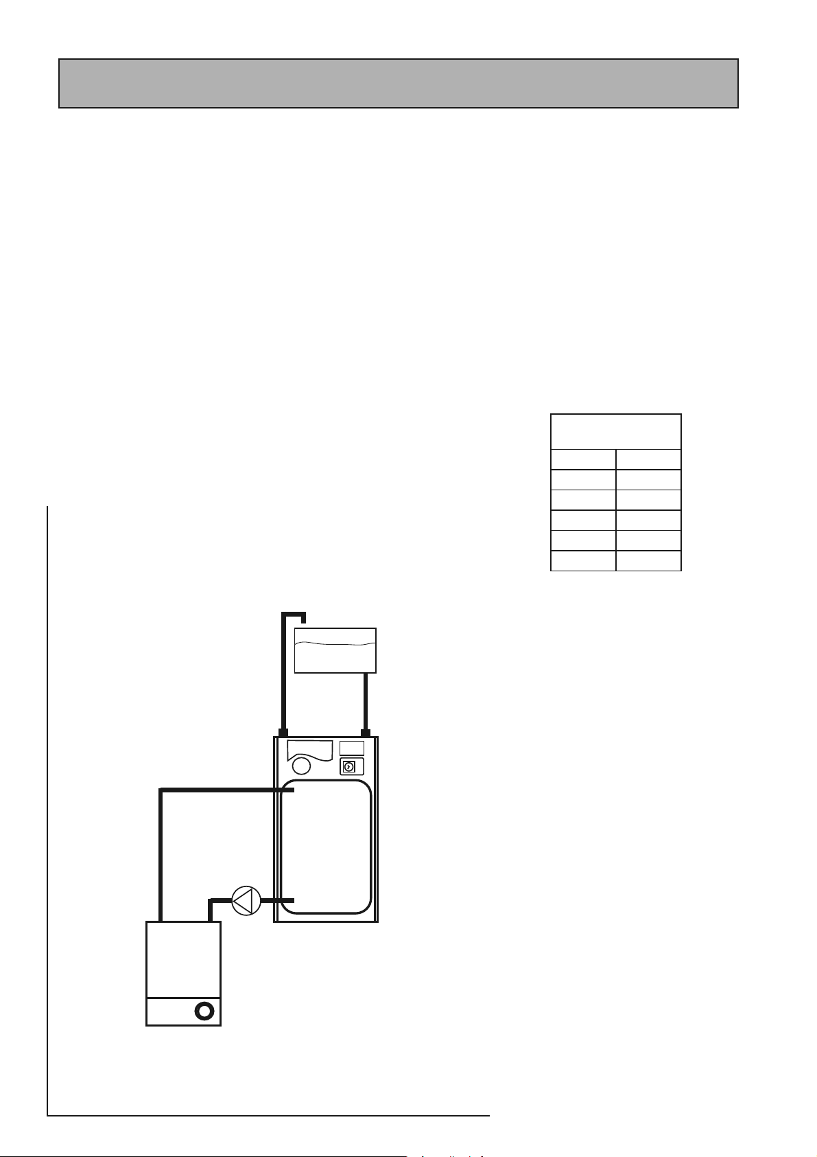
Heating System
&%#ISTERN
0RIMARYFLOW
0RIMARYRETURN
"-!#LASS
"OILER
1.0 DESIGN
1.3 SYSTEM DETAILS
Pipe Sizing/Materials
The primary pipework connecting the boiler and the thermal store should be sized
to achieve a maximum of 8°C rise across the boiler or the maximum temperature
rise specifi ed by the boiler manufacturer, whichever is smaller, but in any instanc e it
should not be less than 22mm copper tube.
Note: There should be no valves in the pipework connecting the boiler to the
BoilerMate A-Class.
The heating circuit operates on the normal primary boiler temperatures i.e. 82°C fl ow
and 71°C return. Therefore any traditional hot water radiators or convectors can be
used with this system and no special over-sizing of the heat emitters is necessary.
All the recommendations with regard to pipework systems in this manual are generally
based on the use of BS/EN Standard copper pipework and fi ttings.
However, we are happy that plastic pipework systems can be used in place of
copper internally as long as the chosen system is recommended for use on domestic
heating systems by the manufacturer and is installed fully in accordance with their
recommendations. We always recommend the use of barrier pipe for these systems.
It is also essential that if an alternative pipework
material/system is chosen the manufacturer
confirms that the design criteria of the new
system is at least equivalent to the use of BS/EN
Standard copper pipework and fi ttings.
Boiler Size
It is only necessary to calculate the heating
requirements in accordance with BS 5449. The
allowances shown below should be added
for domestic hot water. The control system
automatically gives priority to hot water when
necessary.
Allowance for
domestic hot water
Model (kw)
BM125 3
BM145 3
BM185 4
BM210 5
BM225 6
0RIMARYFLOW
0RIMARYRETURN
"OILER
&%#ISTERN
"-!#LASS
Boiler Sited Below BoilerMate A-Class
Any temperature controlled boiler can be
used when the fl ow pipe from the boiler to the
BoilerMate A-Class rises continuously. No valve
shall be fi tted in the primary fl ow or open vent.
Page 14
Page 15
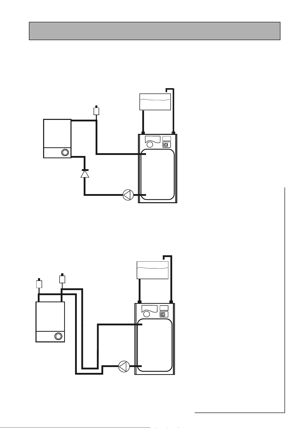
1.0 DESIGN
&%#ISTERN
0RIMARYFLOW
0RIMARYRETURN
"OILER
"-!#LASS
&%#ISTERN
0RIMARYFLOW
0RIMARYRETURN
"-!#LASS
"OILER
1.3 SYSTEM DETAILS
Heating System
Boiler sited above the BoilerMate
!6!UTOMATICAIRVENT
#6'RAVITYCHECKVALVE
!6
"OILER
#6
0RIMARYFLOW
0RIMARYRETURN
&%#ISTERN
"-!#LASS
Any boiler used must be fi tted with an overheat
thermostat i.e. it must be suitable for use in
a sealed system.
The F & E cistern must be fi tted at a height
which will provide the minimum head required
for the boiler and must be at least 250mm
above the highest point of the system.
The height of the water level in the F & E cistern
from the base of the store should be no greater
than 6m.
A gravity check valve should be fi tted in the
boiler return pipework to prevent gravity
circulation between the BoilerMate A-Class and
the boiler during dormant periods.
An automatic air vent will be required on the
flow adjacent to the boiler and depending
upon the pipe layout a manual air vent may also
be required on the return adjacent to the boiler
- see boiler installation insructions.
!6!UTOMATICAIRVENT
!6
!6
"OILER
0RIMARYFLOW
0RIMARYRETURN
&%#ISTERN
"-!#LASS
Boiler sited with dipped flow and return
pipes to the BoilerMate
Any boiler must be fitted with an overheat
thermostat i.e. it must be approved for use in
a sealed system.
An automatic air vent will be required on the
fl ow and return connections adjacent to the
boiler.
The height of the water level in the F & E cistern
must provide the minimum head required by
the boiler and must be at least 250mm above
the highest point of the system.
OV
A-CLASS
BOILERMATE
Page 15
Page 16
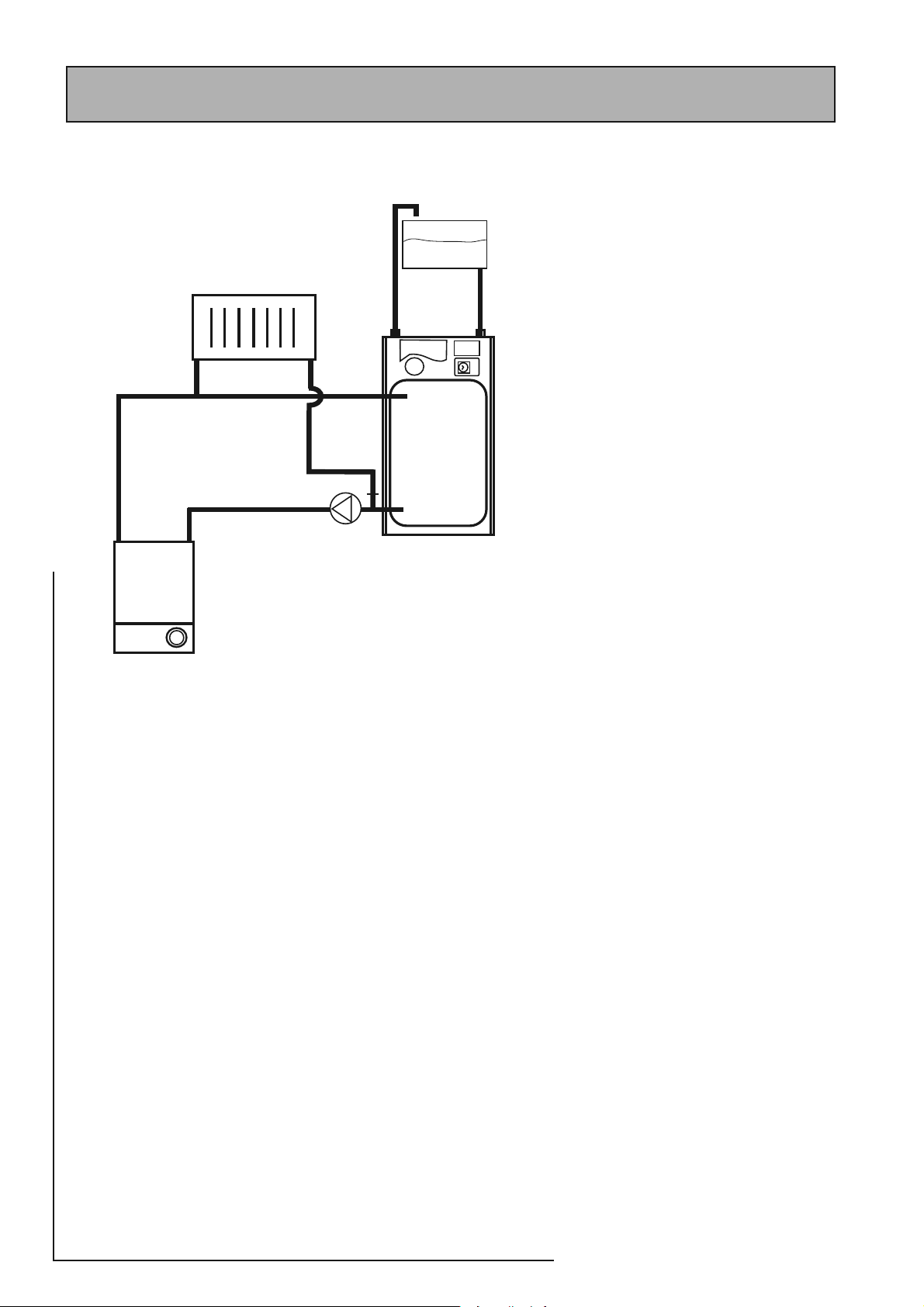
"OILER
2ADIATOR
&%#ISTERN
"-!#LASS
1.0 DESIGN
1.3 SYSTEM DETAILS
Heating System
Connection of Bathroom Radiator/
Towel-Rail for Summer use
If a pumped circuit is required for the bathroom
radiator/towel rail, the fl ow pipework can be
teed anywhere into the primary fl ow between
the boiler and the BoilerMate. The return
pipework can be connected into the 15mm
copper blanked connection provided adjacent
to the boiler pump. We recommend any
radiators/towel rails on this circuit are provided
with T .R.V . ’ s and that the total heat output of the
radiators/towel rails is not more than the fi gure
quoted in the table on page 5.
The radiators will only get hot when the
boiler is fi ring.
It is important that the fl ow rates through these
radiators is adjusted to the minimum required
at the lockshield valves on the radiators. If this
is not done the performance of the BoilerMate
will be adversely affected.
The height of the water level in the F & E cistern
must provide the minimum head required by
the boiler and must be at least 250mm higher
than the highest point of the system.
Alternatively, if full time control is required
of the Summer/Towel rail circuits these can
be piped as a separate zone from the main
heating circuit with their own zone valve and
programmable room thermostat as shown
in Section 2.2 Installation, Zoned Heating
Systems.
Page 16
Page 17
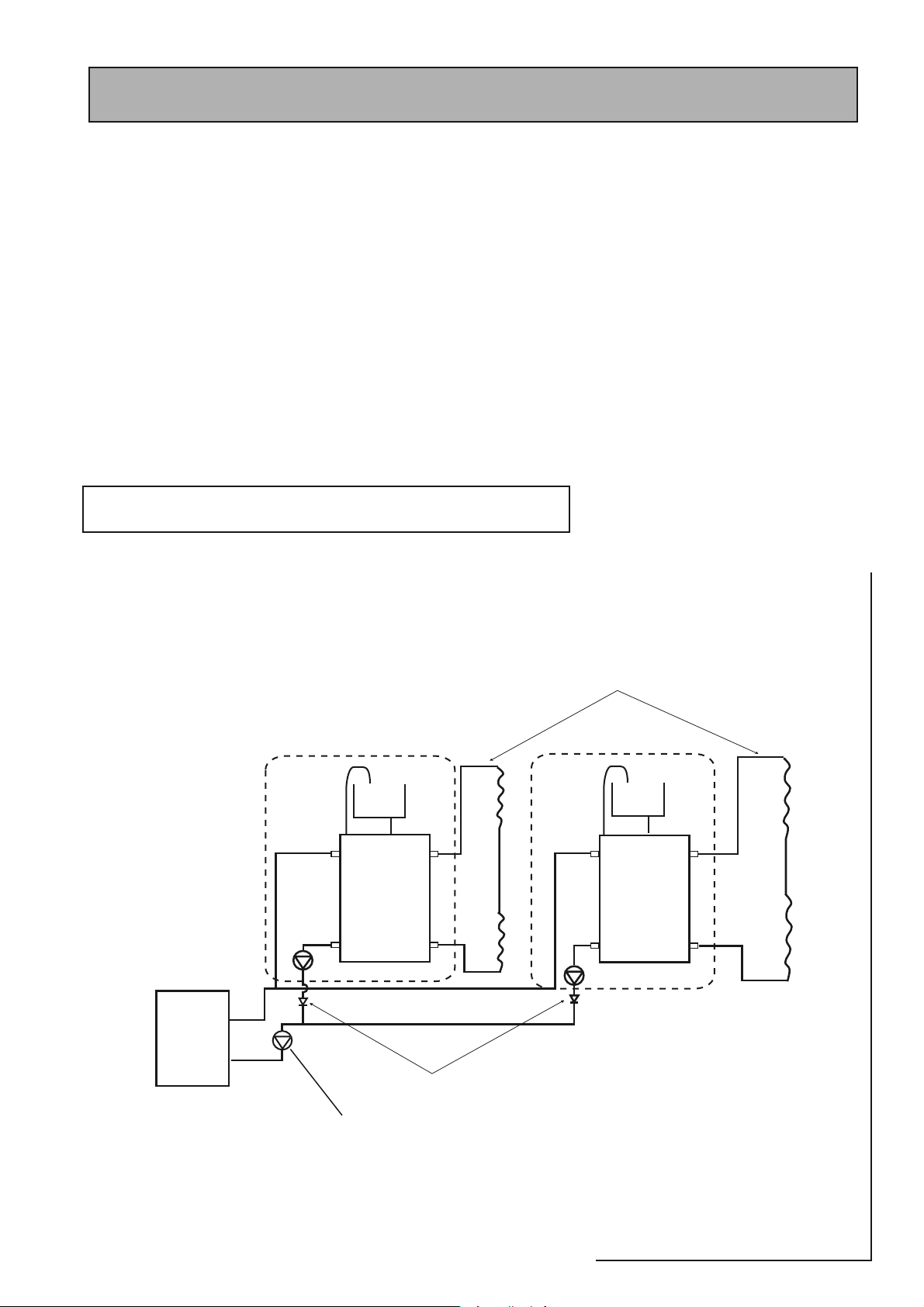
1.3 SYSTEM DETAILS
Heating System
Method of connecting two BoilerMates to one heat source.
If the primary fl ow and return pipework continuously rises from the boiler to the
BoilerMate the recommended method for connecting two BoilerMates to one heat
source is to fi t the BoilerMates as normal but to provide a single check valve on the
branch immediately after each primary pump - see diagram below.
The heating and hot water from each appliance must serve separate zones/bathrooms
within the property.
The electrical supplies from each appliance to the boiler will need twinning so that
the boiler will operate on a call from either/both appliances.
Both primary pumps and the primary pipework sizes should be checked to ensure that
they are adequate for the system that has been installed. If necessary an extra pump
should be fi tted on the common primary return pipework - see diagram below.
The BoilerMate A-Class appliances will not be suitable if the primary pipework
dips or the boiler is located above the BoilerMate.
For further details please ring the Gledhill Technical helpline.
1.0 DESIGN
Boiler
BoilerMate
OV
Single check valve
Heating circuit
BoilerMate
OV
OV
A-CLASS
Fit extra pump if required
BOILERMATE
Page 17
Page 18
"OILER-ATE
/&&
3,/7&,!3().'
-%$)5-&,!3().'
2!0)$&,!3().'
/.
!#,!33
.ORMAL
@3WITCHFAILURE
@3WITCHBACKUPSELECTED
/VERHEATSAFETYTRIP
@3WITCH/N
1.0 DESIGN
1.3 SYSTEM DETAILS
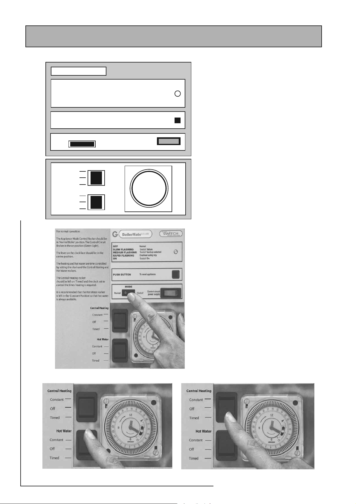
‘Switch’
The BoilerMate A-Class is supplied with ‘Switch ’
which provides a 6kW electrical emergency
back up in the case of failure of the main heat
source i.e. gas boiler.
053("544/.
-/$%
.ORMAL @3WITCH
#ENTRAL(EATING
#ONSTANT
/&&
4IMED
(OT7ATER
#ONSTANT
(7#(/&&
4IMED
4ORESETAPPLIANCE
#ONTROLCIRCUIT
POWERSUPPLY
'RASSLIN
CLOCK
This must NOT be used to provide hot wa ter
only in summer if the main system is working
correctly.
Full details of the electrical requirements are
provided in Section 2.1 Site Requirements and
2.2 Installation.
‘Switch’ will be activated by moving the mode
rocker located on the front control panel into
the ‘switch’ position (see diagram opposite).
This replaces the function of the external boiler
with the internal electric emergency boiler.
The programming of space heating and store
charging is still controlled by the clock and the
hot water and central heating control rockers.
For emergency hot water only put the mode
rocker into ‘Switch’ position, the hot water
control rocker in the constant position and the
central heating rocker to off.
For emergency hot water and heating put the
mode rocker into ‘Switch’ position and the hot
water and central heating control rockers in the
constant position.
Put Mode Rocker to ‘Switch’ position
In this situation the store will charge and the
space heating will be available at all times.
Once the fault has been resolved return to
normal boiler operation by moving the mode
rocker to the normal position and reset the hot
water and central heating control rockers to the
required position.
During Switch operation the central heating
can be operated in a timed mode if required
by setting the central heating control rocker
to timed and the clock/programmer to suit the
times required.
Select HW Only
Select HW & CH
Page 18
Page 19
2.1 SITE REQUIREMENTS
2.0 INSTALLATION
The appliance is designed to be installed in an airing/cylinder cupboard and the
relevant minimum dimensions are provided in section 1.2 Technical Data.
Because of the ease of installation we recommend that the cupboard construction
is completed and painted before installation of the appliance. The cupboard door
can be fi tted after installation.
If the unit needs to be stored prior to installation it should be stored upright in a
dry environment and on a level base/fl oor.
Installation and maintenance access is needed to the front of the appliance and
above the F & E cistern. See Technical Data section for further details.
The minimum dimensions contained in section 1.2 Technical Data allow for the
passage/connection of pipes under the appliance from any direction as long as the
appliance is installed on the installation base provided. If the installation base is not
used extra space may be needed to allow connection to the pipework and the whole
of the base area should be continuously supported on a material which will not easily
deteriorate if exposed to moisture.
The fl oor of the cupboard needs to be level and even and capable of supporting
the weight of the appliance when full. D etails of the weight when full is provided
in section 1.2 Technical Data.
The appliance is designed to operate as quietly as practicable. However, some noise
(from pumps etc) is inevitable in any heating system. This will be most noticeable
in cupboards formed on bulkheads, or at the mid span of a suspended fl oor. In these
cases the situation can be improved by placing the appliance on a suitable sound
deadening material (i.e. carpet underlay or similar).
An electrical supply must be available which is
correctly earthed, polarized and in accordance
with the latest edition of the IEE requirements for
electrical Installations BS 7671.
The electrical mains supply needs to be
230V/50Hz.
A means for disconnection from the supply
mains having a contact separation in all
poles that provides full disconnection under
over voltage category III conditions must be
incorporated in the fi xed wiring in accordance
with the wiring rules. This shall be located
within 1m of the appliance and only serve the
appliance.
The minimum breaking capacity of the main
isolator cable sizes/lengths at 230V shall follow
the recommendations in the table shown
opposite.
If the boiler incorporates a frost thermostat an
extra 3 core 3 amp supply cable will be required
between the boiler and the BoilerMate to
provide a supply to the boiler pump - see 2.2
Electrical Connection for further details.
Cupboard temperatures will normally be higher than in a conventional system
and the design of the cupboard and door will need to take this into account. No
ventilation is normally required to the cupboard.
A suitable location will be needed for the separate feed and expansion cistern.
This will often be at high level in the cupboard housing the BoilerMate A-Class. The
dimensions and clearances are provided in section 1.2 Technical Data. The location
will need to provide a suitable route for the cold feed and expansion pipe as well
as the open safety vent pipe. The location will also need to provide a suitable route
and discharge position for the warning/overfl ow pipe and the ballvalve supply from the
mains cold water system.
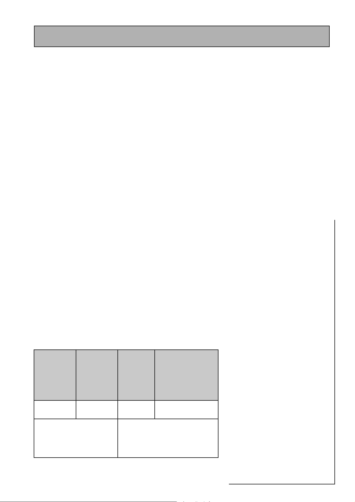
Max. recommended
Nominal
full load
current
28.5 Amps 32 Amps 6 mm
Recommended circuit
protection device - based on
0.4 second disconnection
time
Min rating of
the isolator Cable size
32 A type B circuit breaker to BS EN
60898
or 32A type B RCBO to BSEN 61009
2
cable run-based on
not exceeding 4% of
the nominal voltage
supply of 230 VAC using
a type B breaker
44 metres
OV
A-CLASS
Electrical Supply requirements for BoilerMate A-Class
BOILERMATE
Page 19
Page 20
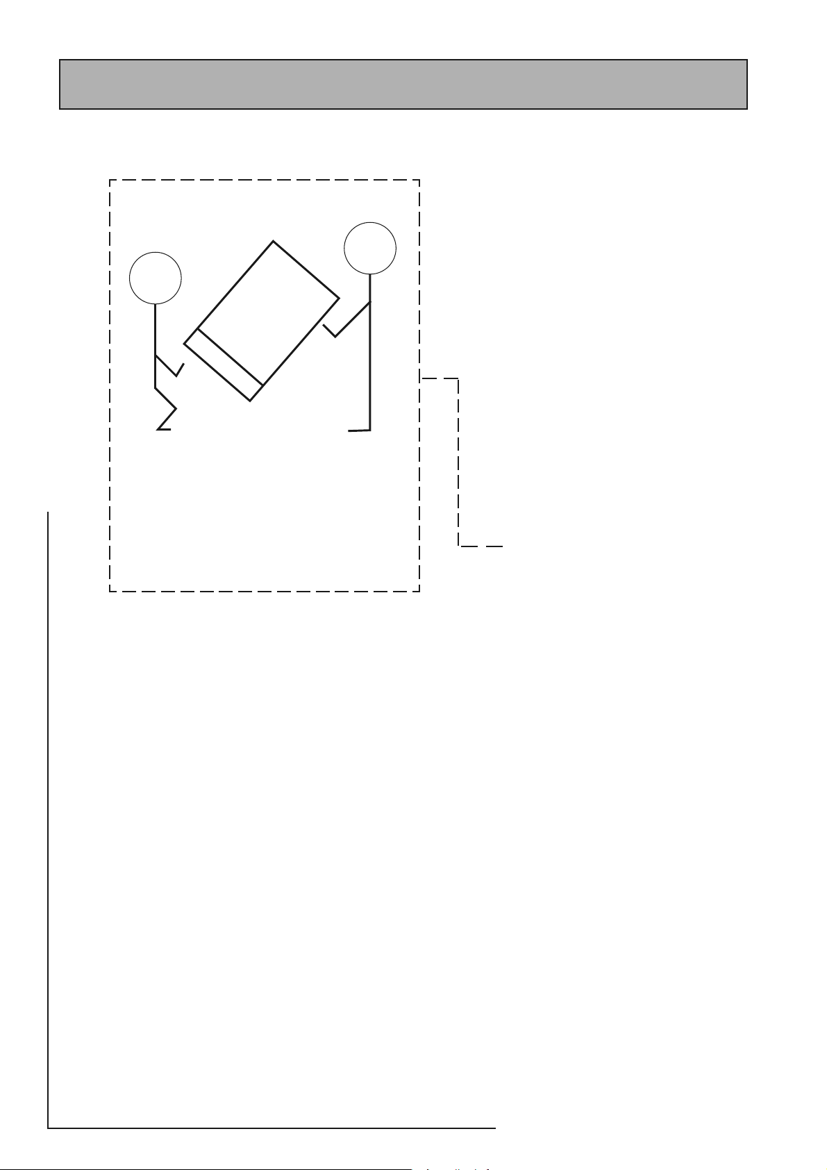
HANDLING
When lifting the unit work with someone of similar build
and height if possible.
Choose one person to call the signals.
Lift from the hips at the same time, then raise the unit to
the desired level.
Move smoothly in unison.
A specifi c manual handling assessment is shown in Appendix D
at the rear of this manual.
2.0 INSTALLATION
2.2 INSTALLATION
Preparation/placing the appliance in
position.
Details of the recommended positions for
termination of the first fix pipework are
provided in section 1.2 Technical Data. The
pipework can be located or its position
checked using the template provided with
each appliance. If these have been followed
installation is very simple and much quicker
than any other system.
The appliance is supplied shrink wrapped on a
timber installation base. Carrying handles are
also provided in the back of the casing.
The feed and expansion cistern complete with
ballvalve, cold feed/expansion and overfl ow/
warning fittings are provided in a separate
box. If fl exible connections have been ordered
these will also be inside the feed and expansion
cistern.
The appliance should be handled carefully
to avoid damage and the recommended
method is shown opposite. Before installation
the site requirements should be checked and
confirmed as acceptable. The plastic cover
and protective wrapping should be removed
from the appliance and the installation base
(provided) and placed in position.
The appliance can then be lifted into position
in the cupboard on top of the base and the
front panel removed by unscrewing the 2
screws and lifting the door up and out, ready
for connection of the pipework and electrical
supplies. The feed and expansion cistern
support shall be installed ensuring that the
base is fully supported and the working
head of the appliance is not exceeded and
the recommended access is provided for
maintenance - see section 1.2 Technical Data.
For further information on manual handling
See Appendix D.
Note: Although the abov e guidance is provided
any manual handling/lifting operations will
need to comply with the requirements of
the Manual Handling Operations Regulations
issued by the H.S.E.
The appliance can be moved using a sack truck
on the rear face although care should be taken
and the route should be even.
In apartment buildings containing a number
of storeys we would recommend that the
appliances are moved vertically in a mechanical
lift.
If it is proposed to use a crane expert advice
should be obtained regarding the need for
slings, lifting beams etc.
Page 20
Page 21
AB
2.0 INSTALLATION
2.2 INSTALLATION
Pipework connections
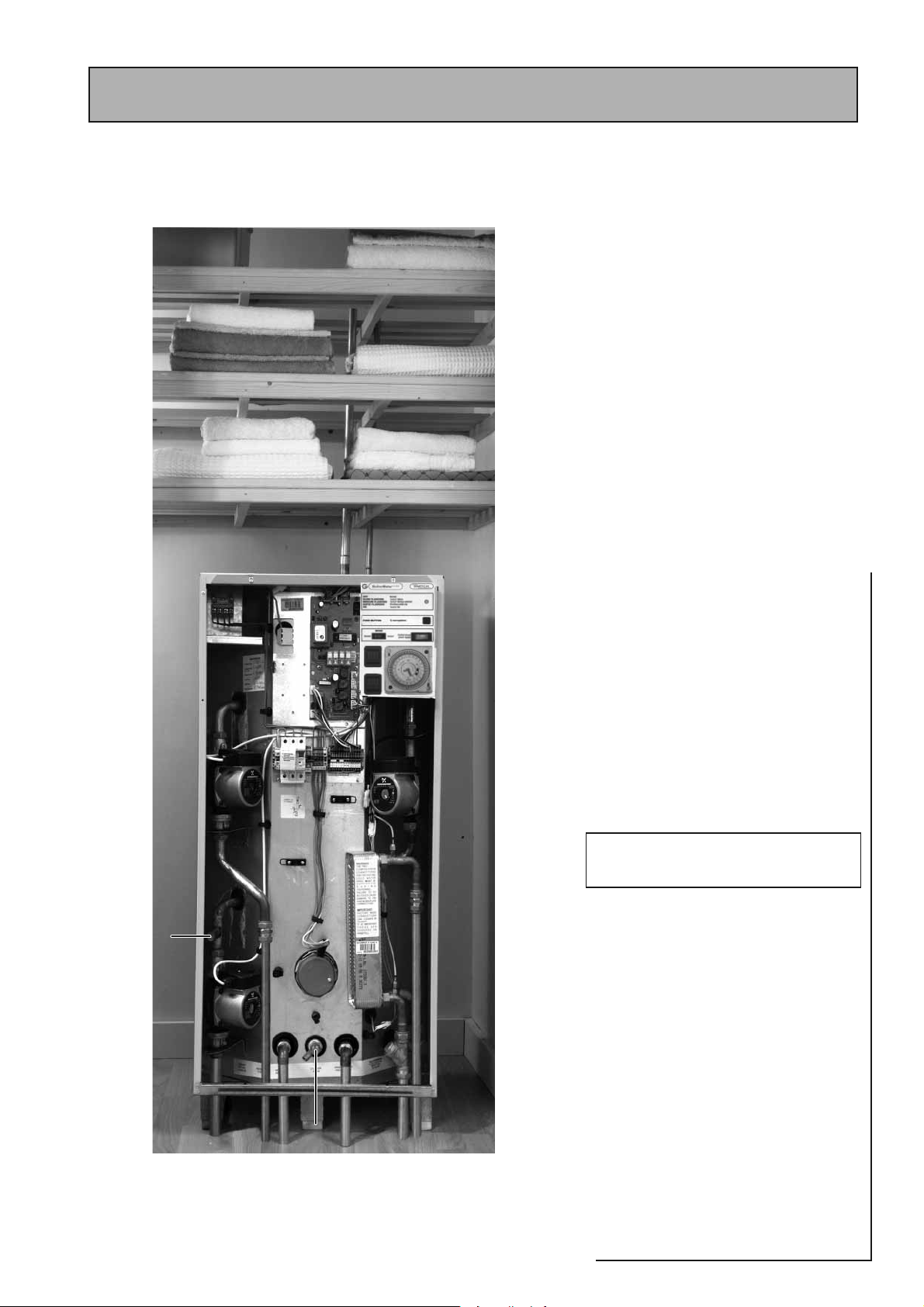
The position of the pipework connections is
shown opposite. The connection sizes and
dimensions are listed in Section 1.2 Technical
Data.
All the connections are also labelled on the
appliance. I t is essential that the pipework is
connected to the correct connection.
Connections A, B, C, E and G are plain ended
copper pipe.
Connections D, F and H are compression
fi ttings.
Connection I is RC½ (½ in BSPT internal).
Connection J is a blanked copper pipe.
A - Safety open vent
B - Cold feed/expansion
C - Primary fl ow (from boiler)
D - Primary return (to boiler)
E - Central heating return
F - Central heating fl ow
G - Domestic hot water to taps
H - Incoming mains cold water
I - Drain (valve is not provided with the
appliance)
J - Primary return for pumped summer
towel rail circuit
Note: The safety open vent and cold feed/
expansion must be connected to the F & E
cistern using the pipework assembly provided.
Do not alter or connect any pressure-relief
device to the vent pipe of this water heater.
All factory made joints should be checked
after installation in case they have been
loosened during transit.
The fi ttings for the feed and expansion cistern
J
should be installed following the instructions
provided in a position to suit the particular
location and the cistern fi tted on its supports/
base.
The cold feed/expansion and safety open vent
should be installed between the appliance and
the feed and expansion cistern.
OV
A-CLASS
DFE CHGI
Page 21
BOILERMATE
Page 22
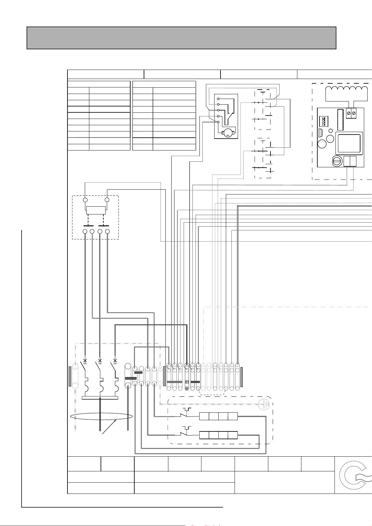
WIRE COLOUR LEGEND
Red
R
BlueBl
BrownBr
Black
B
Orange
Or
Yellow
YY
White
Wh
G/Y
Green / Yellow
Gr
Grey
G
Green
SENSOR LEGEND
S1 & S2
S 3
S 4
S 5
S 6
ID_RESISTOR
Store overheat sensors
Cold Water IN
Domestic Hot Water OUT
Bottom store sensor
Middle store sensor
1K5 Resistor (White)
Bl
5
R
4
3
Br
2
Bl
1
Br
M
GRASSLIN CLOCK
FACTORY FITTED CLOCK
(STANDARD) OPTION
Br
2.0 INSTALLATION
2.2 INSTALLATION
312 4
Wh
Or
Central Heating
2A
5B
2A
5B
Hot Water
Br
3A
1A
3A
1A
6B
R
6B
4B
2 DOUBLE POLE
CHANGE OVER SWITCHES
WITH CENTRE OFF
4B
Br
(PART No XB142)
ON
OPTIONAL EXTRA IF FITTED
2341
SPD1/2A
NL
Br
E
0
RELAY R1
200 - 240Vac 50Hz
4
2
Br
R
Br
2
2.5 mm SID Silicone
Br
16A
MCB 1
1
6
8
R
2
2.5 mm SID Silicone
Br
16A
MCB 2
MCB 3
2
2.5 mm SID Silicone
2
2.5 mm SID Silicone
2
2.5 mm SID Silicone
2
2.5 mm Solid Core PVC
2
2.5 mm SID Silicon
6A
N
N-IH
R
R
L-IH
L-IH
PE-IH
NNN
L1L2L3
SL-W
SL-B
SL-R
SL-H
E
E
SL-F
E
6.0/10.0 mm² Twin & Earth Cable PVC
(10.0mm² is only required when there is a high
ambiant temperature and/or long cable run)
LN
Mains Supply
230VAC 50Hz 32Amps
DRN.
S. McGachie
04-05-07
DATE : MAY 2007
APPROVED
2
2.5 mm SIF Silicone
2
2.5 mm SIF Silicone
2
2.5 mm SIF Silicone
2
2.5 mm SIF Silicone
S. Gataroa
2
4.0 mm SIF Silicone
R
Bl
2 x 3kW Heating Elements
R
SIGN. SIGN.DATE DATE
04-05-07 04-05-07
ISSUE No : 7
Bl
APP'D.CH'KD.DATE
S. Gataora
DO NOT SCALE FROM THIS DRAWING. COPYRIGHT OF THIS DRAWING
IS RESERVED. IT IS NOT TO BE REPRODUCED COPIED OR DISCLOSED
TO A THIRD PARTY EITHER WHOLLY OR IN PART WITHOUT OUR
WRITTEN CONSENT.
© GLEDHILL WATER STORAGE LTD.
Page 22
Page 23
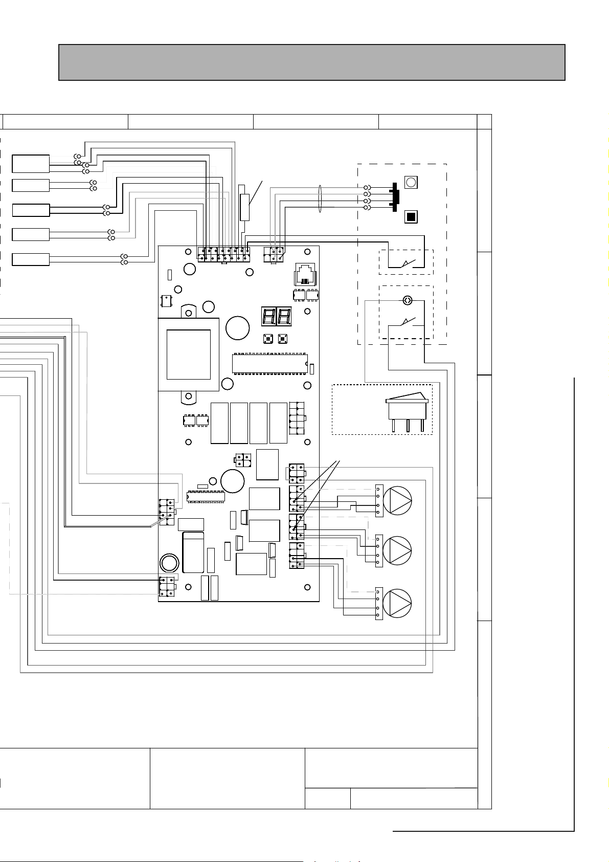
Y
S1 & S2
S3
S4
S5
S6
G
Br
Wh
Br
Wh
Br
Wh
Br
Wh
Br
Wh
SCALE INHIBITOR
2.0 INSTALLATION
2.2 INSTALLATION
8765
R
R
Bl
R
Bl
Y
Y
B
B
O
O
Br
Br
B
O
O
Br
Br
Bl
R
Bl
Y
Y
B
J9
White Covering
Wh
ID_RESISTOR
Wh
B
B
R
J31
Or
Br
B
Flat Ribbon Cable
FRONT PANEL
R
Or
Br
B
Bl
1b
Red LED
Push Button
'MODE'
Switch
BB
Green Neon Illuminated
ON / OFF Switch
A
B
(Heating SL-H)
(Hot Water SL-W)
(Room Stat SL-R)
(Frost Protection SL-F)
2
0.5 mm Tri Rated
G/Y
1a
Br Br
O
1
I
Rocker Switch
J30
terminal
conections
1a
1b
1
C
(1) Connection only used
Wh
Or
B
Y
Br
J28
(1)
(1)
(1)
(1)
BL
BL
J5
J29
if Modulating Pump is fitted
J3
J33
G/Y
J32
J34
B
Bl
Br
Br
Br
B
R
(Boiler ON / OFF)
G/Y
Bl
Br
B
G/Y
Bl
('SWITCH' ON / OFF)
E
N
L
M
Heating
Pump
EM
NE
LN
M
Boiler
Pump
L
DHW
Pump
D
GLEDHILL WATER STORAGE LTD.
SYCAMORE TRADING ESTATE
SQUIRES GATE LANE
BLACKPOOL
LANCASHIRE
FY4 3RL
TITLE
BOILERMATE 'A' Class OV
with Clock (Factory Standard)
New Rail Layout
* All wire sizes 0.5mm² unless otherwise stated
JOB NAME
Electrical Schematic for BOILERMATE 'A' class OV
appliance with factory fitted clock
DRG. SIZE
A3
DRG. NAME
‘A’ Class BoilerMate OV ver 7.ai
Page 23
E
OV
A-CLASS
BOILERMATE
Page 24
2.0 INSTALLATION
2.2 INSTALLATION
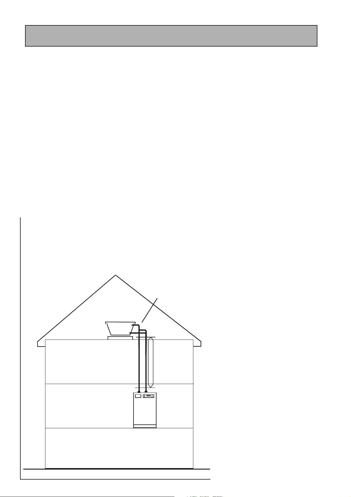
It is normally envisaged that the feed and
expansion cistern will be located in the same
cupboard as the BoilerMate appliance itself to
maintain a dry roof space.
The cold feed/open vent pipework assembly
(as supplied) should be used if it is intended
to install the F & E cistern directly on top of
the appliance
However, if it is necessary to locate the cistern
in the roof space (or on a higher floor) the
cold feed/open vent pipework assembly (as
supplied) should be used to connect to the
F & E cistern and pipework site run by the
installer to connect this to the appliance.
Note: When fi tting the cistern at higher level
this must not be fi tted more than 6 meters
above the base of the BoilerMate A-Class
appliance.
Cold feed / open vent
pipework assembly
(as supplied)
Interconnecting
Pipework
(By Installer)
Obviously, any pipework in the roof space and
the feed and expansion cistern will need to be
adequately insulated to protect against frost
damage.
Combined feed and open vent pipe
arrangements must not be used.
No valves should be fi tted in the safety open
vent which must be a minimum of 22mm
copper pipe or equivalent.
The overflow/warning pipe shall have a
continuous fall, be fitted to discharge clear
of the building and be sited so that any
Overfl ow can be easily observed. I t shall also
be installed in a size and material suitable for
use with heating feed and expansion cisterns in
accordance with BS 5449 and should not have
any other connections to it.
Page 24
Page 25
2.0 INSTALLATION
N
3
241
L
2.2 INSTALLATION
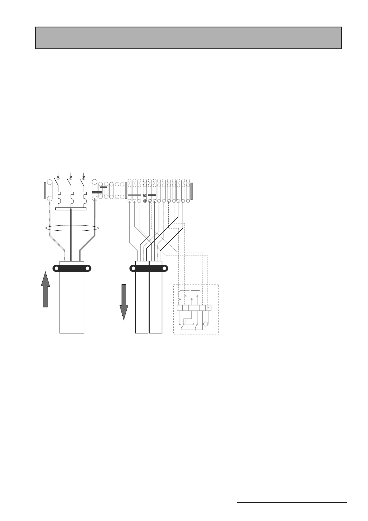
Electrical Connection - Standard Appliance
The BoilerMate A-Class OV is pre-wired to DIN
rail terminals from the A.C.B. and plumbers
are well able to complete the electrical
installation provided they adhere strictly to
the IEE Requirements for Electrical Installations
BS 7671.
All the terminals are suitably labelled.
E
Feed Into
Appliance
BOILERMATE ‘A’ CLASS
EXTERNAL CABLE CONNECTION DIAGRAM
16A
E
MCB 1
LN
2 Core & Earth
6.0 mm
6A
16A
MCB 2
2
MCB 3
N
N-IH
L-IH
L-IH
Feed From
Appliance
PE-IH
2 x 3 Core & Earth
NNN
240 VAC ~
INSTALLER ELECTRICAL
L1L2L3
E
G/YG/YBl Bl BrBr Blk Blk
ROOM STAT CONNECTIONS
240 VAC ~
SUPPLY TO BOILER
2
1.0 mm
SL-W
SL-B
SL-R
E
SL-H
CH On
On
On a ‘No Clock Option’ an external 2
channel controller must be supplied
separately and connected as above.
(Factory Fitted Links between
L1- SL_H - SL_W will need to be removed)
CONNECTIONS
SL-F
Timed Outputs
HW On
Off
On
Note: Do not attempt the electrical work
unless you are competent to carry it out to
the above standards.
Before commencing check that the power
source is in accordance with section 2.1 Site
Requirements and ensure that it is isolated.
Run the external wiring through the service
slot provided in the base of the appliance.
The twin and earth 2 core input cable from the
isolator to the appliance must not be le ss tha n
2
PVC grade to BS 6500.
6mm
This supply cable must be fed via a 32 amp
double pole isolator no more than 2 metres
from the appliance.
Make the connections as shown opposite.
The appliance is provided with a link
between terminals L3 and SL-R on the
HW Off
CH Off
terminal connections. This must be
removed if a room thermostat is fi tted see
opposite.
Clock
Off
Clamp the cables in the clamps provided
below the terminal connections and ensure all
cables are routed to avoid hot surfaces.
The supply to the BoilerMate A-Class must be
protected by a type B MCB to BS EN 60898 of
at least 32 amps rating.
Two installer supplied fl ex cables are required
to connect external room thermostat and
boiler. These cables must each be 4 core and
at least 1mm
For maintenance purposes it is essential that
a 3 pole isolator is positioned within 2 metres
2
or above in size.
OV
of the remote boiler installation. This ensures
the installation meets Corgi requirements for
future maintenance/service.
A-CLASS
Note: The appliance controller is polarity
sensitive therefore if the live and neutral cables
are connected incorrectly the red light on the
front panel will fl ash rapidly and can not be
reset by operating the push button.
BOILERMATE
Page 25
Page 26
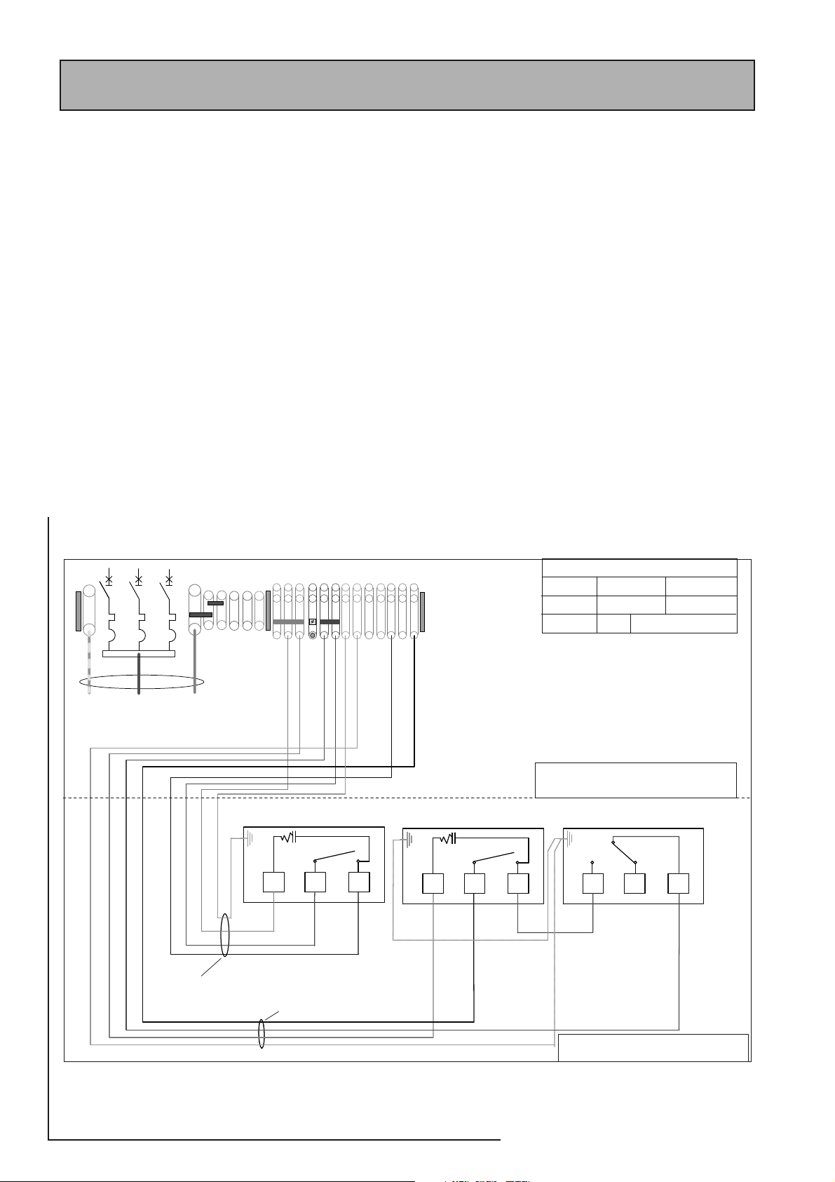
The BoilerMate A-Class incorporates a pump overrun for the boiler pump and
terminal L2 on the terminal strip (as shown on page 23) should only be used if
the boiler requires a permanent live for another purpose.
The boiler manufacturers wiring instructions should be read in conjunction with this
manual.
Before switching on the electrical supply check all the factory made terminal
connections to ensure they have not become loose during transit.
Frost Protection
When frost protection is required for the whole house or where a base temperature
is required during cold weather the central heating and hot water control rocker
switches should be put in the constant position and the room thermostat adjusted
to a suitable setting.
When the location of the boiler means that frost protection is required for the boiler
circuit only a frost thermostat and pipe mounted thermostat should be fi tted in the
normal way and wired back to the special terminal provided in the appliance as
shown below.
2.0 INSTALLATION
2.2 INSTALLATION
16A
MCB 2
Blk Blk
6A
MCB 3
N
16A
E
MCB 1
E
G/Y G/Y
LN
230VAC suppl y
Rated at 6.5kW
32 Amp type B
Circuit Breaker
Bl BlBr Br
L-IH
L-IH
N-IH
PE-IH
ROOM THERMOSTAT
2
Bl
NNN
Br
L1L2L3
1
BoilerMate ‘A’ Class OV Frost External Wiring Diagram
Drawn by: Stephen McGachie Date: 01/08/2006
SL-W
SL-B
SL-R
E
E
SL-H
SL-F
Checked by :
Issue No: 2
Sandy Gataora
Signed :
..............................................................
Date: 01/08/2006
Installer connection terminals within the
Gledhill ‘A’ Class BoilerMate Appliance
FROST THERMOST AT
Temperature setting range: 3 to 20 °C Set to 5 °C
3
Blk
2
1
Bl
Blk
3
PIPE THERMOSTAT
1
Br
2
Br
C
4 Core
4 Core
External installer supplied Room & Frost
Thermostat wiring example
Page 26
Page 27
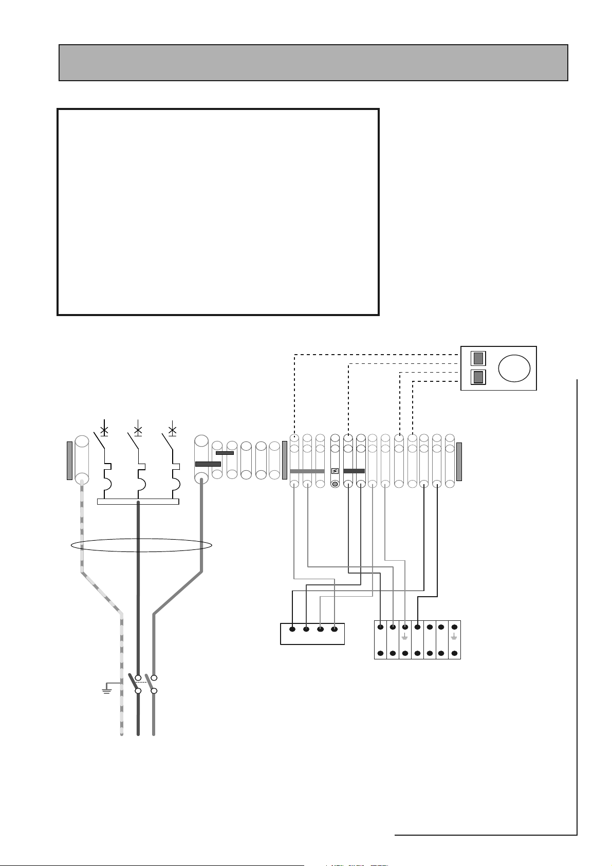
2.0 INSTALLATION
2.2 INSTALLATION
WARNING: THE BOILERMATE A-CL ASS IS FITTED WITH AN ELECTRIC
BACKUP SYSTEM ‘SWITCH’.
IMPORTANT: ELECTRICIAN/INSTALLER PLEASE NOTE.
THE 2 x 16A MCB’s (MCB1 and MCB2) FOR THE ‘SWITCH’ ELECTRIC BACKUP
SYSTEM ARE SUPPLIED SET IN THE ‘OFF’ POSITION BY AN ADHESIVE W ARNING
LABEL. MCB3 IS SUPPLIED SET IN THE ‘ON’ POSITION. THE GAS BOILER CAN BE
COMMISSIONED WITH THE SWITCHES IN THESE POSITIONS AND MCB1 AND
2 MUST NOT BE SWITCHED ON BEFORE THE GAS BOILER HAS BEEN FULLY
TESTED/COMMISSIONED.
AFTER THE GAS BOILER HAS BEEN COMMISSIONED MOVE MCB’S 1 AND 2
TO THE ‘ON’ POSITION WHICH WILL BREAK THE WARNING LABEL AND THEN
COMMISSION THE SWITCH FACILITY.
Electrical Power Supplies - BoilerMate
A-Class with Switch.
Factory fitted programmer
with hot water and central heating
control rockers
16A
E
MCB 1
E
230V ~50Hz r ated at 6,500W
LN
Permanent mains supply
And f us ed at 32A
6.0mm Feed Cable
16A
MCB 2
2
6A
N
MCB 3
Dou ble pol e
Isolator
Within 2 meters
of appliance
N-IH
L-IH
L-IH
PE-IH
SL L E N
Room ther mostat
L1L2L3
NNN
G/Y BlBrBlk G/YBlBr Blk
SL-H
E
E
E
N
L
Boiler Wiring Terminals
(e.g. Gledhill HE Boiler)
SL-W
BoilerMate
SL-B
SL-R
SL-F
Wiring Terminals
L_P
N_ P
SL_B
E
OV
A-CLASS
Typical external wiring of a standard BoilerMate with ‘Switch’
Page 27
BOILERMATE
Page 28
N
N
#ONNECTION
TO"OILER-ATE/6
HEATINGRETURNPIPE
#ONNECTION
TO"OILER-ATE/6
HEATINGFLOWPIPE
#ONNECTION
ELECTERMINALS
TO"OILER-ATE/6
:ONE
0ROGRAMMABLEROOM
THERMOSTAT
0ROGRAMMABLEROOM
THERMOSTAT
:ONE&LOW
:ONE&LOW
-ANUAL)SOLATING
6ALVES
:ONE2ETURN
:ONE2ETURN
490)#!,3#(%-!4)#!22!.'%-%.4/&-5,4):/.%(%!4).'
./4%/.,9:/.%3!2%3(/7.&/2#,!2)49"54&524(%2:/.%3
#!."%!$$%$).4(%3!-%7!9)&2%15)2%$
:ONE
2.0 INSTALLATION
2.2 INSTALLATION
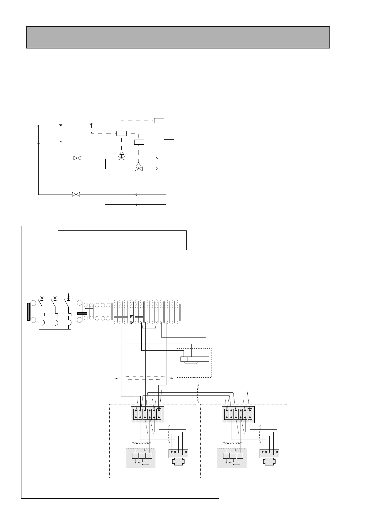
Zoned heating systems
BoilerMate is available in a no clock/multi-zone
version for use where a property has to have
its space heating zoned. Where this appliance
version is to be used it is recommended that
the BoilerMate is located on a raised platform
in the cupboard creating a space below the
appliance to locate the zoning equipment.
The recommended height of the platform
from the fl oor is 250mm. The platform must
be constructed in a material that will not easily
deteriorate if exposed to moisture. It must also
be capable of supporting the weight of the
appliance when full. Details of the weight when
full is provided in section 1.2 Technical Data.
Connecting the zones to the BoilerMate.
The space heating fl ow should be taken from
the BoilerMate connection into the space below
the platform. The fl ow can now be split into the
appropriate amount of zones and a controlling
zone valve fitted to each branch. Each flow
can then be piped to its radiator zone and
the heating return brought back to the space
below the platform. The heating returns can
now be connected together before a single
connection is made to the heating return on
the BoilerMate.
E
16A
MCB 1
16A
MCB 2
BOILERMATE MULTI-ZONE EXTERNAL WIRING DIAGRAM
Note: Terminals L3 AND SL-H must be linked in a no clock/multi-zone option.
6A
N
MCB 3
N-IH
L-IH
L-IH
4 Core cable
PE-IH
3 core 0.75mm²
SL-W
SL-B
L1L2L3
NNN
flex
COM
COM
E
E
E
2
1
3
2
3
1
OFF
ON
OFF
ON
SL-R
SL-H
E
L2
L1SLENL
Junction Box
5 Core flex from
zone valve
L
L
SL-F
1234
Single channel
Grasslin clock
E
NE
AS
AS
4 Core cable
3 core 0.75mm²
A typical way of providing heating and hot water
time control is shown below. However, other
methods can be used such as using a 3 channel
programmer if required.
Hot Water Time
Control
L2
L1SLENL
Junction Box
5 Core flex from
zone valve
flex
E
E
2
1
3
2
3
COM
COM
1
OFF
ON
OFF
ON
L
E
NE
L
AS
AS
TP5000 Programmable room
Thermostat
Zone 1
Zone valve Spring return
with auxiliary switch
TP5000 Programmable room
Thermostat
Zone 2
Zone valve Spring return
with auxiliary switch
Page 28
Page 29
FRONT
PANEL
FRONT
PANEL
FRONT
PANEL
Red
Red
Red
LED
LED
LED
Push
Push
Push
button
button
button
On
On
On
On
SW1
SW1
SW1
SW1
SUPPLY
SUPPLY
SUPPLY
SUPPLY
CIRCUIT
CIRCUIT
CIRCUIT
CIRCUIT
CONTROL
CONTROL
CONTROL
CONTROL
Off
Off
Off
Off
Switch
Switch
Switch
Switch
SW2
SW2
SW2
SW2
OPERAT ION
OPERAT ION
OPERAT ION
OPERAT ION
Normal
Normal
Normal
Normal
Switch SW2
Arcolectri c 394
Switch SW2
Arcolectri c 394
6ERSION
2.0 INSTALLATION
2.2 INSTALLATION
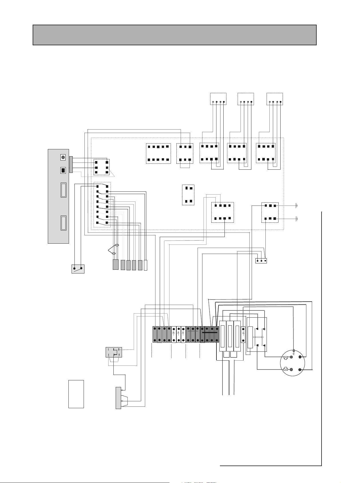
Multi-Zone Wiring Diagram
ENL
ENL
ENL
M
ENL
Pump
Pump
3 7
3 7
N
N
(N) 230V
(N) 230V
M
Boiler
Boiler
blue
blue
brown
black
brown
black
g/y
g/y
2 6
1 5
2 6
1 5
4 8
4 8
J32
J32
white
white
4 8
3 7
2 6
1 5
4 8
3 7
2 6
1 5
4 8
3 7
2 6
1 5
black
black
J5-6 (N) blue
J5-6 (N) blue
2
2
blue
blue
NEN
N
NEEN
N
PD1
PD2
PD1PD1
PD2PD2
2
2
10mm
10mm
CH
CH
Red (E l ect ric back u p )
Red (E l ect ric back u p )
Brown (boiler on/off)
Brown (boiler on/off)
g/y
g/y
brown
brown
J30
J30
5 10
4 9
3 8
2 7
5 10
4 9
3 8
blue
blue
red
red
black
black
white
white
RS 197-7592
RS 197-7592
2-Pole Change over
2-Pole Change over
J31
J31
1 2 3
4 5 6
1 2 3
4 5 6
1 2 3
4 5 6
J9
J9
1 2 3 4 5 6 7 8
9 10 11 12 13 14 15 16
1 2 3 4 5 6 7 8
9 10 11 12 13 14 15 16
black
black
brown
brown
orange
yellow
orange
yellow
Red & blue
Red & blue
ID_Resistor
S3: DHW_in
S3: DHW_in
Overhe at & co n t ro l sens o r
S1 & S2
Overhe at & co n t ro l sens o r
S1 & S2
HW
HW
CH + HW
CH + HW
OFF
OFF
with centre off switch
with centre off switch
ID_Resistor
S6: Store_ top
S6: Store_ top
S4: DHW _out
S4: DHW _out
S5: Store bottom
S5: Store bottom
2 7
J3-4 (BLR) br own
J3-4 (BLR) br own
J28-2 ( RS ca lling) b lac k
J28-2 ( RS ca lling) b lac k
J28-8 ( HW c alling) oran ge
J28-8 ( HW c alling) oran ge
SL_B
SL_B
SL_R
SL_R
Boiler ‘switched’ live (L)
Boiler ‘switched’ live (L)
Room stat ‘switched’ live (L)
Room stat ‘switched’ live (L)
3 6
1 6
1 6
J28-7 (CH calli ng) white
J28-7 (CH calli ng) white
SL_W
SL_W
HW ‘swi tch ed’ liv e (L)
HW ‘swi tch ed’ liv e (L)
2 5
3 6
2 5
3 6
2 5
J3
J3
J29
J29
J29
SL_H
SL_H
E
E
EE
EE
CH ‘switched’ live (L)
CH ‘switched’ live (L)
4 8
4 8
1 4
1 4
1 4
J33
J33
2 4
1 3
2 4
1 3
2 4
1 3
orange
orange
brown
brown
L_1
L_1
L_2
L_2
L_3
L_3
Neutral
Neutral
Permanent
Permanent
Live (L) 230V
Live (L) 230V
M
ENL
M
Pump
Pump
blue
blue
3 7
2 6
1 5
3 7
2 6
1 5
J28
J28
J5-3 (L)
J5-3 (L)
brown
brown
2.5mm
2.5mm
E
EE
PD3
PD3PD3
DHW
DHW
brown
black
brown
black
g/y
g/y
4 8
4 8
J34
J34
Main PCB
Main PCB
blue
blue
Illuminated
Illuminated
Illuminated
J3-6 (L)
J3-6 (L)
red
red
Control circuit supply
Control circuit supply
Control circuit supply
red
red
A1A2
A1A2
1314
1314
C2
C2
blue
blue
M
ENL
M
Pump
Pump
blue
black
blue
black
brown
brown
3 7
2 6
1 5
3 7
2 6
1 5
J5
J5
3 6
2 5
1 4
3 6
2 5
1 4
3 6
2 5
1 4
brown
brown
On/Off switch – SW1
On/Off switch – SW1
On/Off switch – SW1
red
red
23
23
24
24
2.5mm
2.5mm
2
2
red
red
2.5mm
2.5mm
red
red
2
2
Earth to Panel
Earth to Panel
C
C
o
o
high temp flying cables
high temp flying cables
2
2
Switch Immersion heater with
•2 x 3kW elements
•2 x auto reset OHT set at 95 +0,-5
Switch Immersion heater with
•2 x 3kW elements
•2 x auto reset OHT set at 95 +0,-5
•1.5m long 2.5mm
•1.5m long 2.5mm
2
2
2
2
2.5mm
2.5mm
2.5mm
2.5mm
blue
blue
blue
E
E
L
CT
L
CT
blue
N
N
OV
%LECTRICAL3CHEMATICFORA"OILER-ATE!#LASS/6-ULTIZONE-ODEL
L
L
E
E
N
clock
PD1: 16A mcb
PD2: 16A mcb
PD3: 6A mcb
PD1: 16A mcb
PD2: 16A mcb
PD3: 6A mcb
clock
Gras s lin
Gras s lin
1 2 3 4
1 2 3 41 2 3 4
N
A-CLASS
2
2
10mm
10mm
Mains supply
Mains supply
230V, 50Hz, 32A
230V, 50Hz, 32A
BOILERMATE
Page 29
Page 30
2.0 INSTALLATION
2.3 COMMISSIONING
Open the incoming stop valve and fill the domestic mains cold and hot water
systems.
Fill the whole of the primary heating system with potable water through the feed
and expansion cistern.
Check the water level in the feed and expansion cistern and adjust the ballvalve if
necessary.
Check the whole of the primary heating and domestic hot and cold distribution
system, including the boiler and BoilerMate OV, for leaks.
It is essential that all systems function properly for optimum performance.
To achiev e this, the primary system should be commissioned in accordance with good
practice and generally in accordance with the requirements of BS 6798, BS 5449 and
BS 7593.
Full details of the requirements are given in PAS 33:1999 under Section 10
Commissioning.
Model Volume to be added to the system (litres)
Corrosion inhibitor agent
Sentinel X100 Fernox MB1
BMA125 1¼ 1¼
BMA145 1½ 1½
BMA185 2 2
BMA215 2¼ 2¼
BMA225 2½ 2½
Model Volume to be added to the system (litres)
Cleansing agent
Sentinel X300 Fernox Superfl oc
BMA125 1½ 1½
BMA145 1½ 1½
BMA185 2 2
BMA215 2¼ 2¼
BMA225 2½ 2½
When using either cleansing or corrosion
inhibitor chemical, the manufacturers
instructions must be followed.
Cleansing the Primary System
When determining the quantity of cleanser
required, be sure to allow for the increased
volume of water in the primary circuit due to
the thermal store - see section 1.2 T echnical
data for volumes.
In most cases the quantities shown opposite
will be adequate for up to a typical 3/4
bedroom property.
Primary Water System T reatment
Although the BoilerMate has no special water
treatment requirements, the radiators and
other parts of the circuit will benefi t from the
application of a scale and corrosion inhibitor
such as Sentinel X100 or a Protector such as
Fernox MB1.
When determining the quantity of inhibitor
required, be sure to allow for the increased
volume of water in the primary circuit due to
the thermal store - see section 1.2 Technical
Data for volumes.
In most cases the quantities shown opposite
will be suitable for up to a typical 3/4 bed
property.
POWERFLUSHING/CLEANING OF THE HEA TING
SYSTEM
If it is proposed to ‘powerfl ush’ the heating
system we would recommend that the
BoilerMate appliance is isolated from the
heating system being cleaned. F ailure to do this
could seriously damage the appliance.
When carrying out the work always comply
fully with the manufacturers instructions for
the powerfl ushing equipment being used.
If in any doubt please consult our Technical
Helpline.
Page 30
Page 31
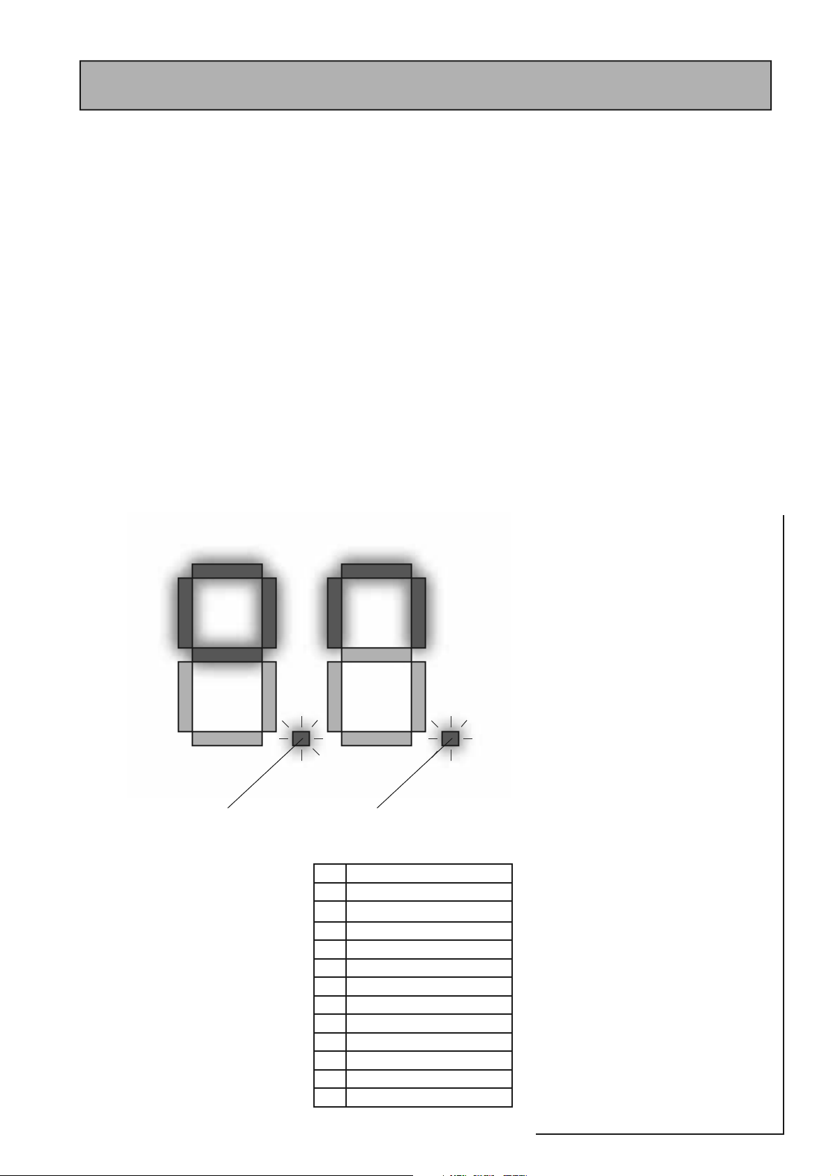
2.0 INSTALLATION
2.3 COMMISSIONING
Once the system is fi nally fi lled turn down the servicing valve for the ballvalve
in the F & E cistern to the point where the warning/overfl ow will cope with the
discharge arising from a ballvalve failure.
Cleansing Hot/Cold Water System Treatment
Fully fl ush and if necessary chlorinate the hot and cold water system in accordance
with the recommendations in the Model Water Byelaws and BS 6700.
Note: Incorrect chlorination will damage the plate heat e xchanger so car e must
be taken that the system is fully fl ushed.
Commissioning the BoilerMate control system
For maximum system effi ciency the store thermostat must be in control of the boiler
i.e. the boiler c ycles on the store thermostat and not on its integral thermostat. The
BoilerMate control system will automatically commission itself to match the actual
performance of the installed boiler. However the operation of the control system
should be checked as follows.
(
6
(
6
(
6
6
(
(a) Check that the BoilerMate front panel mode
rocker is in the ‘normal’ position. Put the hot
water control rocker in the constant position
and the central heating control rocker in the
off position.
(b) The boiler will not start i.e there will be
no 240V ac start signal at BoilerMate terminal
‘SL-B’ until:-
• The heating programmer calls for hot water
/heating which will bring display segment V1.1
on, and
• Store sensors are calling for heat which will
bring display segments H1.1 and H1.2 on (see
opposite)
(c) Set the boiler thermostat to maximum and
commission the boiler as per manufacturer’s
instructions and ensure that the flow
temperature reaches more than 77oC before
switching off. Display segments H2.3 and V2.1
will be on whilst the boiler is fi ring.
(d) Check and adjust the speed of the boiler
pump to provide a differential temperature of
about 11ºC across the fl ow and return when
the space heating is off.
(e) Check on the A.C.B. that the appliance
reaches a suitable temperature ie above 75ºC
6
(
6
@&LASHING
#ONTROLLERWORKING/+
Note: If both ‘dots’ are fl ashing then the
controller is working. However it is a
warning of limited/alternative control
functionality
6
6
(
@&LASHING
,OCKOUT&AILURE
LED Description
H1.1 Middle store sensor calling for heat
H1.2 Bottom store sensor calling for heat
H1.3 Spare
V1.1 HW Programmer calling for heat
V1.3 CH Programmer calling for heat
V1.4 Room thermostat calling for heat
H2.1 PHE pump on
H2.2 3 port valve on (for heating)
H2.3 Boiler/heating system pump on
V2.1 Boiler on
V2.2 Switch on / electric boost on
V2.4 Boiler boost mode on
Page 31
(f ) To manually check the ‘switch’ electric
backup is working, move the mode rocker on
front panel display from ‘normal’ to ‘switch’
position. The electric backup operation can
now be checked. Dra w a bath full of hot water
from the appliance to lower the temperature
and bring ‘switch’ into operation.
This is easily checked with the aid of a clamp
meter that should show a current drawn
of around 26 amp. If a suitable meter is not
available a bath full of hot water should be
drawn from the appliance after which the store
temperature should be noted. With no further
demand a rise in store temperature of 5 – 10
in about 15-20 minutes (dependent on store
size) should be observed. Display segment
V2.2 will be on whilst ‘Switch’ is working. Once
it has been proved that ‘ switch’ is working move
the mode rocker switch back to the normal
position.
o
C
OV
A-CLASS
BOILERMATE
Page 32

2.3 COMMISSIONING
2.0 INSTALLATION
Commissioning Space Heating
(a) The central heating is best commissioned when the store is hot and therefore
should be carried out after commissioning the BoilerMate.
(b) Move the central heating control rocker to the constant position, set heating
programmer to continuous and ensure that the room thermostat is calling for heat.
This will be indicated by display segments V1.3 and V1.4 being on respectively. The
BoilerMate controller will now:-
• Turn on the central heating pump and this will be indicated by display segment
H2.2 being lit.
(c) Wait until the heating cir cuit has reached its normal temperature before balancing
the system in the usual way to achieve a temperature drop of about 10
(d) Set the programmer and room thermostat as per manufacturer’s instructions
supplied with the appliance and ensure that the programmer instructions along with
the user instructions for the appliance are left with the user.
Commissioning Domestic Hot Water System
(a) When the store is hot, open a hot water tap nearest to the appliance at
approximately 6 litres/minute. After about 2 – 3 seconds, the plate heat exchanger
pump will start. This is indicated on the A.C.B. by display segment H2.1.
(b) The hot water fl ow temperature should settle at about 52ºC. Close this tap and
open the hot bath tap at maximum fl ow rate and record the fl ow rate and the hot
water temperature in the ‘Benchmark’ logbook.
o
C.
These Instructions should be placed along with
the component manufacturers instructions in the
pocket provided on the rear of the front panel.
The front panel should then be refi tted.
Important Do’s and Don’ts
1. DO check the incoming mains water
pressure and fl ow rate are adequate.
(The preferred range of mains pressure is
2-3bar).
2. DO check that all connections are in
accordance with the labelling on the thermal
store.
3. DO adjust the ballvalve so that the
water level in the F & E cistern when
the system is cold is correct and does not
overfl ow when the whole of the
system is at maximum temperature.
4. DO make sure that there is adequate
clearance above the F & E cistern to
service the ballvalve.
5. DO ensure that the range rated
appliances are set at the highest output
and the boiler thermostat is set to maximum
for all boilers.
(c) Close the hot water tap(s) and after few seconds, the plate heat exchanger pump
will stop running and display segment H2.1 will turn off.
(d) It is recommended that the hot water rocker is left on constant so that hot
water is always av ailable. The cen tral heating rocker should be left on timed and
the clock set to control the times heating is required.
Hand over to User
(a) Explain the system and the BoilerMate appliance controls to the user.
(b) Explain how to operate the heating and hot water controls to the user . This should
include setting ‘ on ’ and ‘off’ times and the r oom temperature on the room thermostat
as well as the use of thermostatic radiator valves.
(c) Advise on boiler operation and maintenance advised in the boiler manual.
(d) Explain how to select and check the operation of the emergency backup electric
boiler ‘switch operation’ - if there is a failure of the boiler.
(e) Handover appliance and room thermostat user instructions and put the completed
“Benchmark” logbook and the appliance instruction manual in the pocket on the
inside of the appliance front panel.
(f) DON’T place any clothing or other combustible materials against or on top of this
appliance.
This product is covered by the ‘Benchmark’ scheme and a separate commissioning/
service log book is included with this product. This must be completed during
commissioning and left with the product to meet the Warranty conditions
offered by Gledhill.
6. DO ensure that the water level in the
F & E cistern is at least 250mm above
the highest point on the radiator circuit or the
highest point of the system.
7. DO check that the F & E cistern is not more
than 6m above the base of the BoilerMate
appliance.
8. DO insulate any exposed pipework in the
BoilerMate cupboard.
9. DO plumb the overfl ow/warning pipe in a
20mm internal diameter pipe material which
is suitable for use with a heating F & E cistern,
in accordance with BS 5449 (such as copper)
and ensure it has a continuous fall and
discharges in a conspicuous external position.
10. DO check the pump settings
a. The boiler pump should be set to give a
temperature difference across the boiler
of 8°C or less.
b. The heating pump should be set to give a
temperature difference across the flow and
return of not more than 11°C.
c. The hot water plate heat exchanger pump
should be set at maximum.
Page 32
Page 33

2.0 INSTALLATION
2.3 COMMISSIONING
10. DO ensure that the bypass valve for the
heating system (if fi tted) is set correctly.
11. DON’T use a combined feed and vent on
BoilerMate installations.
12. DON’T use a BoilerMate on a sealed primary
i.e. closed system.
13. DON’T use pipe smaller than 28mm
between the boiler and the BoilerMate when
the boiler rating exceeds 20kW (about 68,000
Btu/h).
14. DON’T use dipped fl ow and return between
the boiler and the BoilerMate unless the boiler is
fi tted with an overheat thermostat. If necessary
check with the suppliers of the boiler.
15. DON’T operate the ‘switch’ backup facility
until the system is fully fitted, vented and
commissioned.
16. DON’T place any clothing or other
combustible materials against or on top of
this appliance.
Page 33
OV
A-CLASS
BOILERMATE
Page 34

3.0 SERVICING
3.1 ANNUAL SERVICING
No annual servicing of the BoilerMate A-Class
is necessary.
However, if required, the operation of the
controls and a hot water performance test can
be carried out when servicing the boiler to
prove the appliance is working satisfactorily
and within its specifi cation.
3.2 CHANGING
COMPONENTS
Free of charge replacements for any faulty
components are available from Gledhill during
the in-warranty period (normally 12 months).
After this, spares should be obtained direct
from Gledhill using the ‘Speed Spares’ service, or
through any of the larger plumbers merchants/
specialist heating spares suppliers.
Help and advice is also available from the
Technical Helpline on 08449 310000.
However , all components are readily accessible
and can be changed quickly and easily by the
installer using common plumbing practice.
Note:
The pump is a Grundfos UPR 4 wire type and
any replacement must be the same model,
obtained direct from Gledhill. Failure to do
this will affect the hot water performance.
This type of pump is also available as an option
for the boiler and heating pumps. Be sure to
check this and replace on a like for like basis.
Page 34
Page 35
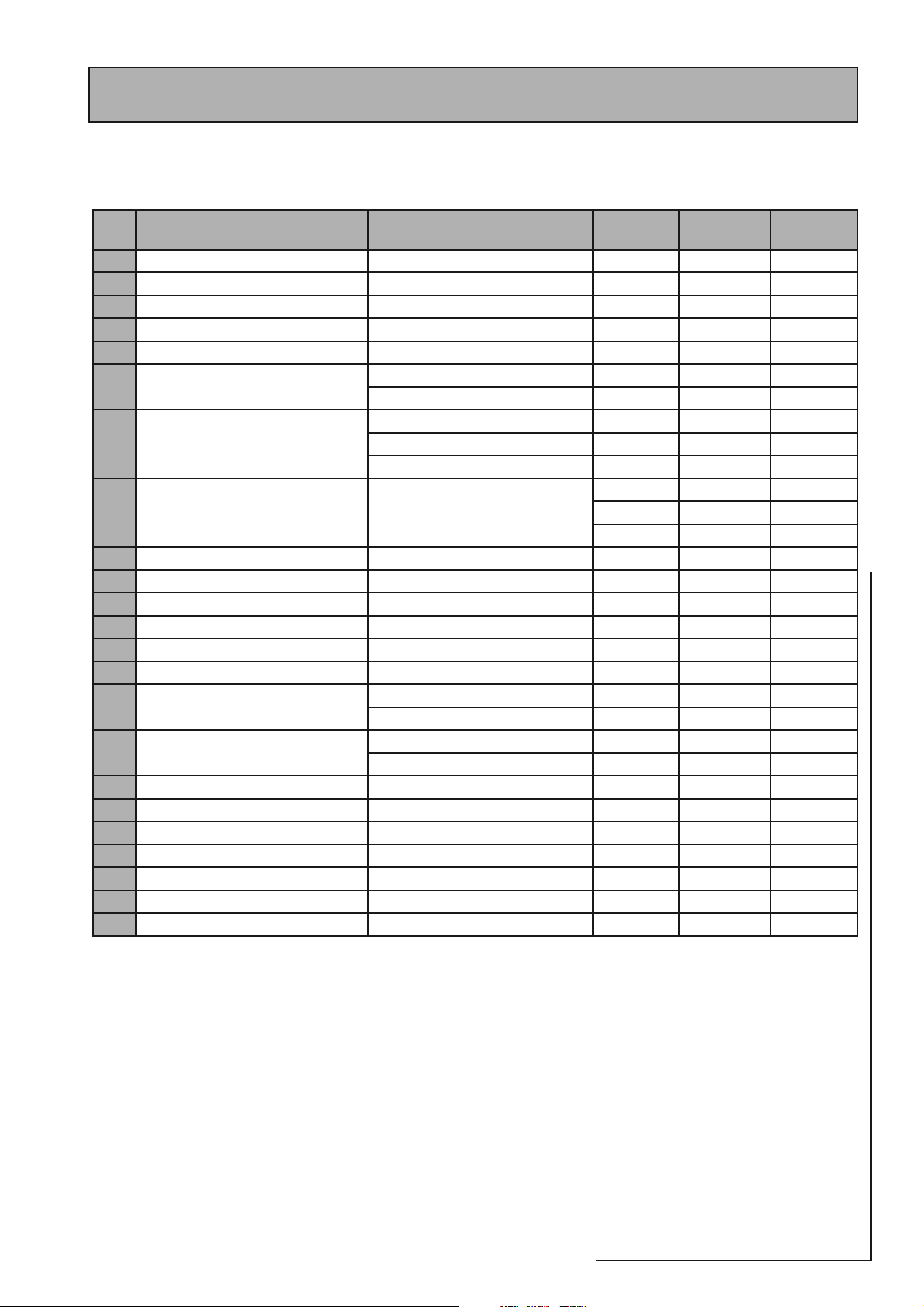
3.0 SERVICING
3.3 SPARE PARTS LIST
Key
No.
1 PHE pump Grundfos UPR 15-50 (modulating) GT089 All
2 Plate heat exchanger (PHE) SWEP 24 Plate heat exchanger GT017 All
3 PHE pump isolating valve - inlet Vemco GT133 All
4 PHE pump isolating valve - outlet Vemco GT135 All
5 CW inlet Y-line strainer XB314 Al
6 Boiler / Central heating pump Grundfos, UPR 15-50 (optional) XB004 125, 145, 185
7 Boiler / Central heating pump isolating
valves
8 1 x 6 kW switch immersion heater Wardtec XB468 125, 145, 185
9 Main PCB controller Argus Vision GT490 All
10 Bottom store sensor Tasseron GT198 All
11 Middle store sensor Tasseron GT198 All
12 Top (OHT) sensor Tasseron GT199 All
13 Front panel display R H Technical XB414 All
14 Front panel display wiring harness R H Technical XB057 All
15 Internal fuses/circuit protection MCB Single Pole 6A x 1 XB025 All
16 Switch contactor Relay XB178 All
17 DIN Rail terminals Wago NSI All
18 Complete DIN rail assembly Wago XB465 All
19 Complete wiring harness All
20 On-Off rocker Arcoelectric CA006 All
21 Programmer EMC Grasslin XB215 All
22 Central heating and hot water rocker Arcoelectric XB059 All
23 DHW In/Out Sensor x 2 Tasseron GT198 All
Description Supplier/Components Stock Code NoModels Gas Council
Grundfos, UPS 15-60 (standard) XB241 210, 225
Vemco - Inlet XB121 125, 145, 185
Vemco - Outlet XB121 125, 145, 185
Vemco, Inlet & Outlet XB122 210, 225
XB469 215
XB470 225
MCB Single Pole 16A x 2 XG175 All
Relay Clip XB179 All
No.
Page 35
OV
A-CLASS
BOILERMATE
Page 36

3.4 FAULT FINDING
3.0 SERVICING
Despite everyones best efforts some problems could occur and lead to complaints
from the householder.
Complaints can be grouped into the following three main categories:-
1. The system is noisy
2. Hot water service is unsatisfactory
3. Space heating is unsatisfactory
The following checks should be carried out by the installer before calling the
manufacturer.
1. Causes of a ‘Noisy’ System
Noisy pump operation
Check the level of water in the F & E cistern - adjust and vent the pump/system
if necessary.
Check the pump speed setting of the boiler pump - reduce if necessary but ensure
that the temperature rise across the boiler does not exceed 8°C.
Check the pump speed setting of the heating pump - reduce if necessary but ensure
a temperature difference across the fl ow and return does not exceed 11°C.
Check and adjust if necessary the heating system bypass valve.
Check that the radiators are correctly balanced.
Noisy boiler operation
Check the fl ow rate through the boiler at full gas rate by measuring the temperature
rise across the boiler. If the temperature rise is greater than 8°C, then increase
the pump speed.
Check the level of water in the F & E cistern and the working head on the boiler.
Check and vent the system if necessary.
Noise when hot water tap is opened
If the plate heat exchanger pump is noisy when the hot water tap is opened, then
check the level of water in the F & E cistern and vent the pump if necessary.
Water hammer - loose pipework and/or tap washers.
3. Causes of ‘Unsatisfactory Space Heating’
Check the boiler thermostat - this should be
set at maximum.
Check that the boiler fl ow temperature before
it is turned off by its own internal thermostat
or the store sensor is adequate - it should not
be less than 77°C.
Check the operation and the settings of
the heating programmer and the room
thermostat.
Check that the heating system pump is
circulating the water to the radiator circuit.
If some rooms are not being heated properly,
then balance the system/check the operation
of the thermostatic radiator valves (if fi tted).
Overfl ow from Feed and Expansion Cistern
Check that the controlled level of water in the
cistern is no higher than necessary. Adjust if
required.
POWERFLUSHING/CLEANING OF THE HEATING
SYSTEM
If it is proposed to ‘powerfl ush’ the heating
system we would recommend that the
BoilerMate appliance is isolated from the
heating system being cleaned. Failure to do
this could seriously damage the appliance.
When carrying out the work always comply
fully with the manufacturers instructions for
the powerfl ushing equipment being used.
2. Causes of ‘Unsatisfactory Hot Water Service’
Check that the BoilerMate is full of water i.e. level of water in the F & E cistern is
correct when system is cold.
Check boiler thermostat - this should be set at maximum.
Check that the boiler fl ow temperature is adequate when it stops fi ring. Boilers should
provide a fl ow temperature of 82 ± 3°C but temperatures as low as 75°C will allow the
BoilerMate A-Class to provide a satisfactory performance.
Check that the store is charging to at least 75°C.
Check that the hot water plate heat exchanger pump stops and starts when the
hot water tap is opened and closed.
Check that the plate heat exchanger pump is set at maximum speed.
Check that the space heating and hot water load is not greater than the boiler output
and that the BoilerMate A-Class model is suitable for the type of dwelling.
If all the above checks are satisfactory then it is possible that the performance of
the heat exchanger is impaired by scale. In this case the hot water fl ow rate will be
noticeably less than the cold water fl ow rate. Replace with a factory exchange unit
and re-check hot water performance.
If in any doubt please consult our Technical
Helpline.
Note: If the A.C.B. board is replaced it will
need setting to the appliance type - see
pages 9 and 10 for further details.
The system controls/operation should then
be checked.
If the problem cannot be resolved the switch
emergency electric backup should be switched
on and operated in accordance with the
instructions on the label fi tted to the appliance
until the installer/manufacturer can attend.
When requesting a visit from the
manufacturer the installer must have the
completed ‘Benchmark’ commissioning/
service record sheet to hand to enable help
to be provided.
Page 36
Page 37
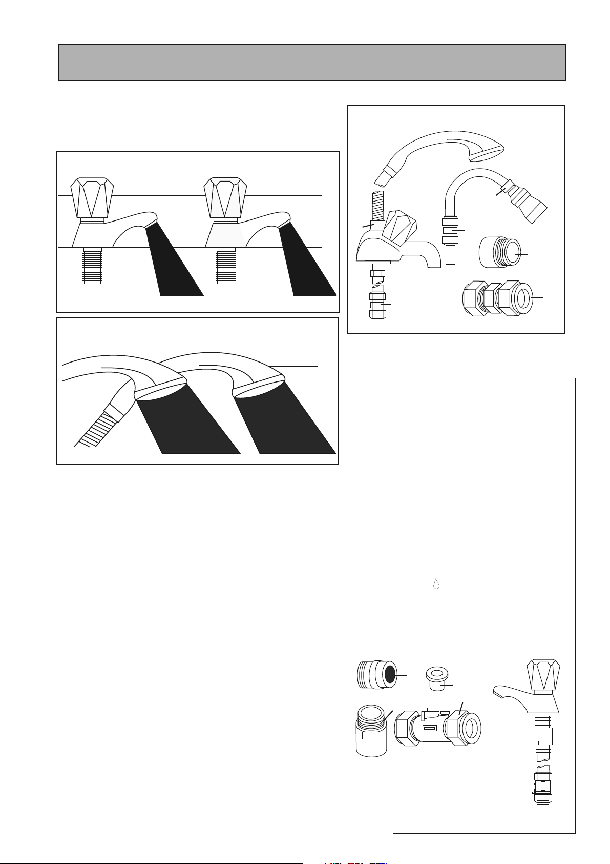
WATER SAVINGS
WATER RELATED COSTS CAN BE REDUCED BY GOOD
PLUMBING PRACTICE.
TAPS & MIXERS
APPENDIX A
1
2 TAP
HALF OPEN
Unregulated
OVER
20 L/M
Fitted with regulator
5, 6 OR
8 L/M
SHOWERS
Unregulated
25 - 30 l/m
Vast quantities of water are needlessly run off to waste due to
Taps , Mixers and Showers discharging fl ow rates far in excess of
the rates required for them to perform their duties.
The contrasting fl ow rates shown on this leafl et clearly illustrate
the savings that can be made whilst still providing a good
performance.
British made Aquafl ow Regulators provide constant fl ow rates
by automatically compensating for supply pressure changes
between 1 bar & 10 bars.
To facilitate installation into the wide range of plumbing
equipment which is encountered in the U.K, Four Fixing
Options are available:-
Regulated
10 - 12 l/m
OPTIONS FOR SHOWERS
1
2
2
1
2
4 FIXING OPTIONS FOR TAPS &
MIXERS
1. MK Range - Combined Regulators & Aerator
for screwing onto Taps & Mixers with internal
or external threads on their noses. Anti Vandal
models also available.
2. MR05-T Range - Internal Regulators. Push-fi t
into Tap or Mixer seats. Produced in three
sizes - 12.5mm (BS1010), 12mm & 10mm,
Flangeless models also available for Taps
with Low Lift washers.
3. MXF Standard Range - Screw on tail
models for Taps & Mixers. Fix onto the tails
before fi tting the tap connectors. Available in
3/8", 1/2", 3/4" and 1" BSP.
4. Compression Fitting Range - “In Line” regulators
housed in 15mm & 22mm CXC Couplers &
Isolating V alves. “ ”UK WFBS listed by the Water
Research Centre. Isolation valves available for
slotted screwdriver operation or with coloured
plastic handles.
bodied push-fi t couplers & valves.
Now available also in plastic
1. MXF “DW” Range - For fi tting behind Fixed Shower Heads
or onto Flexible Hoses for Handshowers (preferably onto
the inlet end when lightweight hoses are used).
2. Compression F itting Range. “In Line” regulators as in Option
4 for Taps & Mixers.
Information by courtesy of
AQUAFLOW REGULATORS LTD
Haywood House, 40 New Road, Stourbridge, West Midlands DY8 1PA
TELEPHONE (01384) 442611 FAX: (01384) 442612
Page 37
1
3
4
3
OV
A-CLASS
BOILERMATE
Page 38
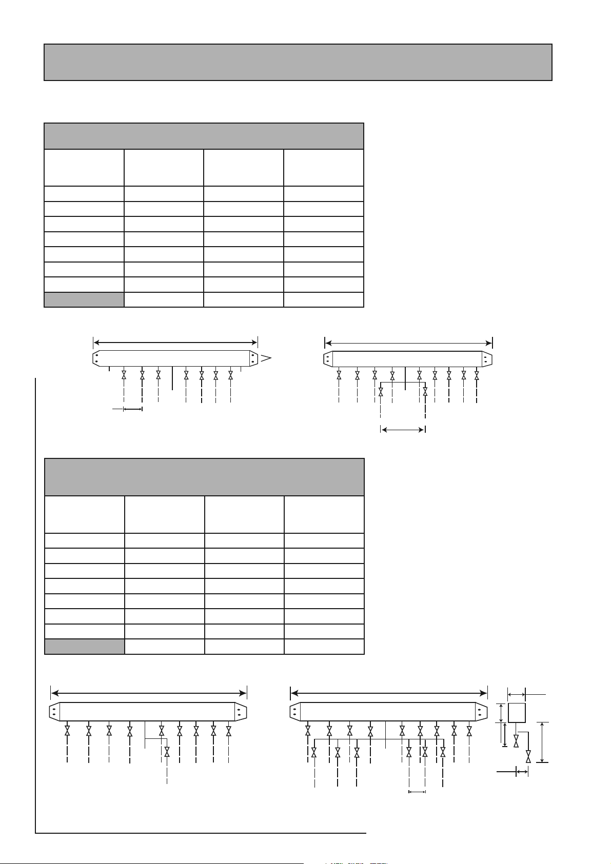
MANIFOLDS
APPENDIX B
Manifold type: 1 - Stock Code MIP 050
(one bathroom, one en suite shower room, one cloakroom, one kitchen)
Flow regulator
(litres/minutes)
Terminal fi tting Hot water
manifold outlets
Quantity
Cold water
manifold outlets
Quantity
18 Bath tap 1 1
9 Hand basin 3 3
12 Kitchen sink 1 1
9 Toilet cistern None 3
9Shower1 1
12 Washing machine 1 1
9 Dishwasher None 1
Total 7 11
595mm
2 No 6mm
fixing holes
9 l/mm
blank
12 l/mm
blank
55mm
18 l/mm
12 l/mm
9 l/mm
9 l/mm
inlet
A (hot)
9 l/mm
18 l/mm
Two sets of manifolds are available as an
optional extra. Each set comprises a separate
hot and cold water manifold. Both are
provided with a 22mm inlet connection
located centrally. All outlet connections are
15mm compression. The centre to centre
dimension of each branch is 55mm.
595mm
12 l/mm
9 l/mm
9 l/mm
9 l/mm
165mm
inlet
9 l/mm
9 l/mm
9 l/mm
9 l/mm
B (cold)
9 l/mm
12 l/mm
Manifold type: 2- Stock Code MIP 060
(two bathrooms, one en suite shower room, one cloakroom, one kitchen,
one utility room)
Flow regulator
(litres/minutes)
Terminal fi tting Hot water
manifold outlets
Quantity
Cold water
manifold outlets
Quantity
18 Bath tap 2 2
9 Hand basin 4 4
12 Kitchen sink 2 2
9 Toilet cistern None 4
9 Shower 1 1
12 Washing machine 1 1
9 Dishwasher None 1
Total 10 15
595mm
18 l/min
12 l/min
C
12 l/min
(hot)
9 l/min
inlet
9 l/min
9 l/min
9 l/min
9 l/min
12 l/min
18 l/min
18 l/min
9 l/mm
12 l/min
9 l/mm
The arrangement of each manifold is supplied
as shown. This provides the best balance of
flows but the flow regulators/duty of each
branch can be changed if required as long
as a reasonable balance is maintained. If it is
necessary to change or clean the fl ow regulator
this can be done without needing to drain the
system by closing the valve and removing the
screwed cover below the white plastic cover.
The manifolds are designed to be used with
plastic pipework and are supplied complete
with isolation valves and flow regulators
on each branch. They would normally be
installed in the same cupboard as the thermal
storage appliance (as shown below) but can
be installed in another cupboard close to the
appliance if required.
595mm
12 l/min
9 l/mm
9 l/min
inlet
9 l/min
9 l/mm
55mm
9 l/min
9 l/min
9 l/mm
12 l/min
9 l/mm
D
18 l/min
(cold)
85mm
90mm
85mm
90mm
195 mm
Page 38
Page 39
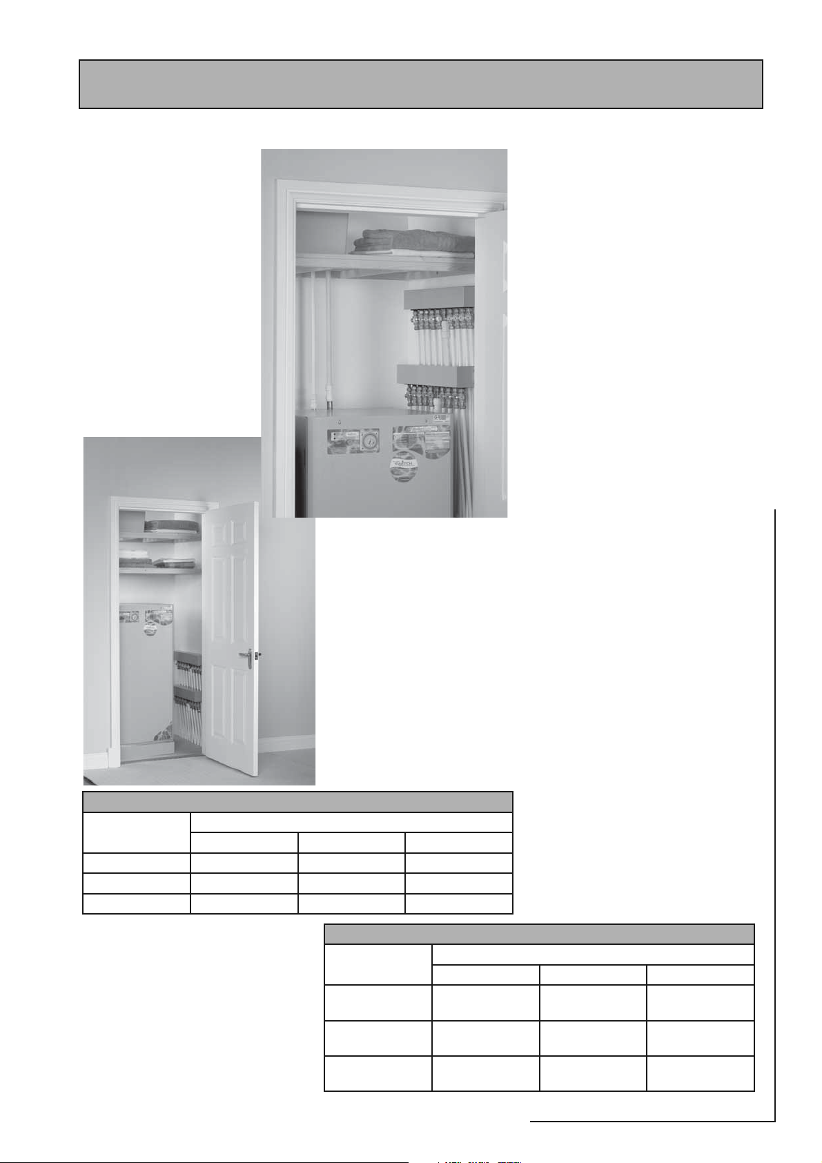
An optional location where cupboard space is tight
APPENDIX B
The pressure loss through a flow regulator
at the designated fl ow rate is about 1.8 bar.
Therefore for the fl ow regulator to control the
fl ow rate at pre-set level, the inlet pressure must
be greater than 1.8 bar. If the inlet pressure
is lower, the fl ow rate will be correspondingly
less than the pre-set values.
The maximum equivalent pipe lengths from
the manifold to the terminal fi ttings can be
estimated from the above information and
the resistance characteristics of the pipes.
The examples presented below are for 15mm
copper pipe in table 1 and for plastic pipework
in table 2.
The preferred solution where space will allow
Table 1: Maximum equivalent pipe length in 15mm copper
Inlet pressure
(bar)
2.0 25 10 5
2.5 75 30 15
3.0 150 60 30
Maximum equivalent length of pipe (m)
@ 9 l/m @ 12 l/m @ 18 l/m
Table 2: Maximum equivalent pipe length in plastic pipe
Inlet pressure
(bar)
2.0 1.5 15mm : 10 15mm : 4.5
2.5 3.0 15mm : 20 15mm : 9.0
3.0 4.5 15mm : 30 15mm 13.5
Maximum equivalent length of pipe (m)
@ 9 l/m @ 12 l/m @ 18 l/m
22mm : 40
22mm : 80.0
22mm : 120
Page 39
OV
A-CLASS
BOILERMATE
Page 40
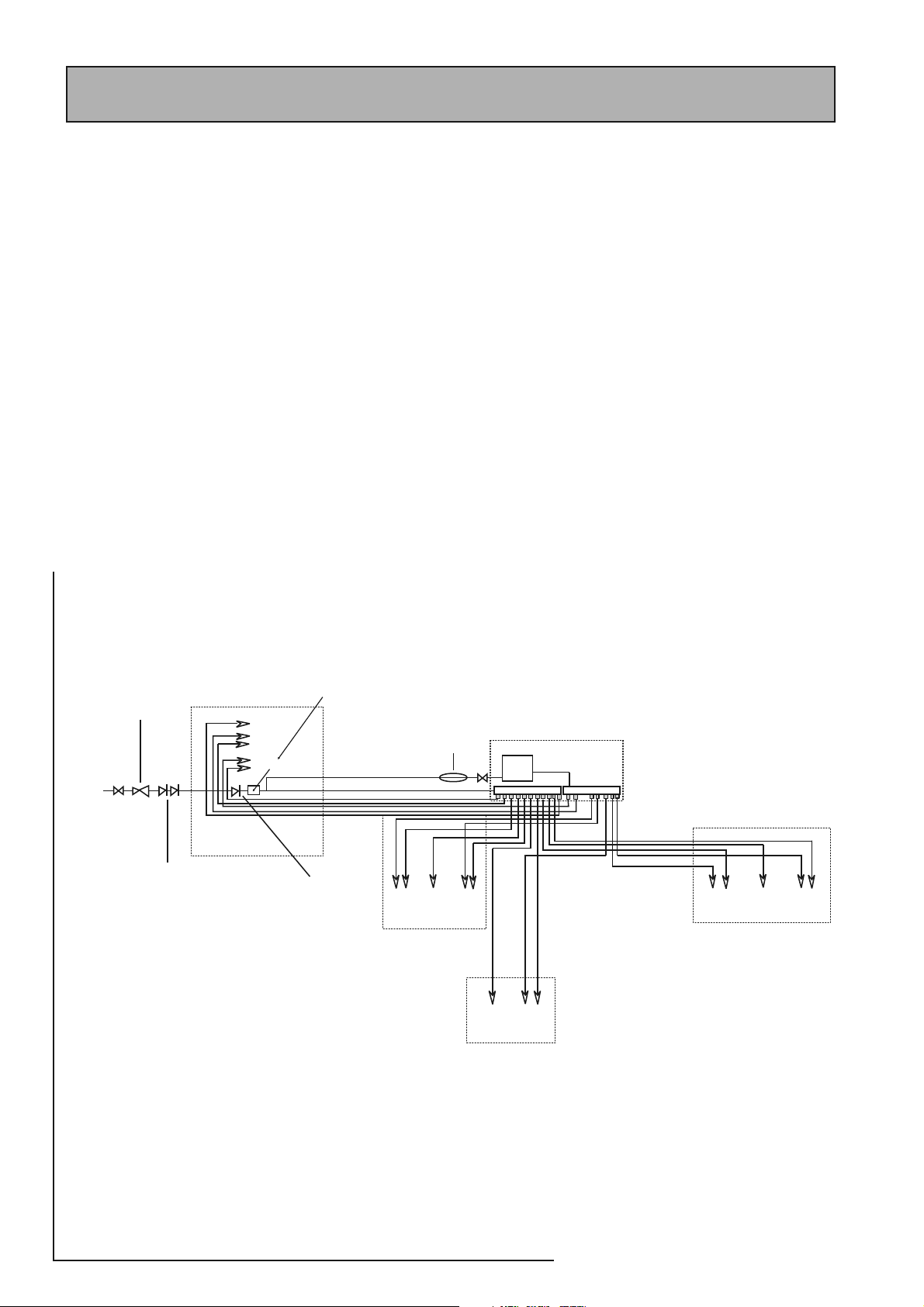
APPENDIX B
The size of the distribution pipes supplying
the manifold should be calculated using
the method set out in BS 6700. A typical
diagrammatic arrangement of a system
using Manifold Type 1 is shown below.
This is only meant to show the principles
involved and the actual connection of
fi ttings to the manifold will need to suit the
arrangements shown on page 35.
Note 1 - If it is proposed to fi t chemical water
treatment such as a water softener this should
be fi tted in this location and the cold water
branch in the sink should be branched off the
cold water main prior to the treatment device
instead of the cold water manifold.
Any other isolating/control valves and
backflow protection devices should be
provided as necessary to comply with the
Water Regulations.
Pressure limiting valve
NOT REQUIRED at pressures
below 5 bar unless any system
components have a lower
maximum working
pressure
Mains
supply
Double check
valve NOT REQUIRED
unless supply pipe
services more than
one dwelling
DW
WM
Kitchen sink
Kitchen
See Note 1
Check valve
NOT REQUIRED
unless chemical
water treatment
is fitted
NOT REQUIRED
Bath Toilet
cistern
Bathroom
Scale
inhibitor
Hand
basin
Toilet
cistern
Cloak room
Hand
basin
Airing
cupboard
Thermal
Store
Shower
En-Suite
Toilet
cistern
Hand
basin
Page 40
Page 41
APPENDIX C
GUIDANCE NOTES
2
Inhibitor (Corr osion & scale protection
of primary heating cir cuit)
On filling the heating system and before the boiler is fired up, it is important to ensure the
system water is treated with a suitable corrosion inhibitor, in accordance with the boiler
manufacturer’s instructions.
Since the concentration of inhibitor present in a system can become diluted, for a number of
dif ferent reasons, the system should be checked annually and r e-treated as r equired, or after
ever y full or partial drain-down. A water treatment manufactur er’s test kit
may be used to check the correct concentration of inhibitor in the system.
Where recommended by a boiler manufacturer, a ‘physical corrosion
protection device’ may be fitted in the primary pipework in accordance
with the boiler manufacturer’s instructions.
The Benchmark log book should be completed indicating the date and
details of any of the above products added and a permanent label
should be fixed to the system in a prominent location.
3
Scale protection
(Domestic hot water service)
Where a combi boiler and/or a hot water storage vessel is installed in areas where the mains
water can exceed 200ppm Total Hardness (as defined by BS 7593: 1993 Table 2) a scale
reduction device should be installed, in accordance with the boiler manufacturer’s instr uctions.
The levels of water hardness may be measured using a water hardness test kit.
BUILDING REGULATIONS
Completion of the BENCHMARK log book requires that the ‘competent person’ undertaking the
installation and commissioning provide information relating to Cleaning, Inhibitor and Scale Pr otection.
This will demonstrate that the work complies with the requirements of the appropriate Building
Regulations.
This Guidance Note is produced on behalf of its members by the Central Heating Information Council.
For a full list of members visit www.centralheating.co.uk and for further advice on water treatment contact the
following members:
Culligan Sentinel Fernox Salamander Engineering Scalemaster
Heating & Hotwater Information Council, 36 Holly Walk, Leamington Spa,
Warwickshire CV32 4L Y Te l: 0845 600 2200 Fax: 01926 423284
www.centralheating.co.uk
OV
A-CLASS
Benchmark is managed by The Heating & Hotwater Information Council
Page 41
BOILERMATE
Page 42

APPENDIX D
MANUAL HANDLING OF APPLIANCE PRODUCTS
Description
Manual handling means any transporting or supporting of a load (including lifting,
putting down, pushing, pulling, carrying or moving) by hand or bodily force.
Scope
This assessment will cover the largest Appliance, namely ElectraMate, GulfStream,
BoilerMate, SysteMate, PulsaCoil, Accolade and Stainless Lite manufactured by
Gledhill.
The maximum weight of the largest product in each range is 98kg and the size is
595 x 595 x 2020 mm high.
Main Hazards
Vision may not be clear due to the size of the products.
Adopting an incorrect method of lifting may cause injury, attempting to lift these
products will require help from others. ( Team lifts)
Control Measures
Manual lifting procedure
The lift, key factors in safe lifting are:
a. Balance
b. Position of back
c. Positioning of the arms and body
d. The hold
e. Taking the lead for team lifts
a. Balance - Since balance depends essentially upon the position of the feet,
they should be apart about hip breadth with one foot advanced giving full
balance sideways and forward without tension. In taking up this position,
lifting is done by bending at the knees instead of the hips and the muscles
that are brought into use are those of the thigh and not the back.
b. Position of back - Straight - not necessary vertical. The spine must be
kept rigid, this coupled with a bent knee position, allows the centre line of
gravity of the body to be over the weight so reducing strain.
e. Taking the lead for team lifts- As
more than one person is required
for these products ensure that one
person is taking the lead. This may
be you so ensure that each person
that is helping is made aware of the
weight and of the items listed within
this assessment. Make sure you and
any others helping know the route
you intend to take that it is clear of
any obstructions. Never jerk the load
as this will add a little extra force and
can cause severe strain to the arms,
back and shoulders. If there are steps
involved decide on where you will
stop and take a rest period. Move
smoothly and in unison taking care to
look and listen to others helping with
the lift. Where possible use a sack
truck to move the product over long
flat distances, only lift the products
when necessary. If in doubt stop and
get more help. The unit handles and
packaging with the pallet have been
designed to ensure that two-four
people can assist when lifting up
stairs or over longer distance.
Individual capability
Individual capability plays an important
part in handling these products. Persons
above average build and strength will
find it easier and should be in good
health. Persons below average build and
strength may require more rest periods
during the handling process.
Pregnant women should not carry out
this operation.
Persons who are not in good health
should seek medical advice prior to
commencing any lifting or manual
handling operation.
Residual risk
c. Positioning of arms and body - The further arms are away from the side,
the greater the strain on the shoulders, chest and back. Keep elbows close
to the body arms should be straight.
d. The hold - Before lifting ensure you have a good hold. Two handles are
provided on Appliance products at the top rear side, these allow one or
two persons to have a purposely-designed hold at the top of the appliance
to ensure easy lifting at the top of the product. Each appliance is supplied
with a pallet, which has been attached to the unit via the packaging. The
pallet will also allow for one or two persons to get a good hold.
Following the guidelines given above will
reduce any risk to injury.
All persons carrying out this operation
must be fully trained and copies of the
specific risk assessment made available
for inspection and use in their training
process.
Further guidance on Manual Handling
can be obtained from the Health and
Safety Executive. Manual Handling
Operations Regulations 1992.
Page 42
Page 43

Gledhill
CONDITIONS OF SALE & GUARANTEE TERMS
(Water Storage)
AMD. JUNE 2008
Ltd
1. Gledhill (Water Storage) Ltd (“We” or “Gledhills”) only do business upon the Conditions which appear below
and no other. Unless we so agree in writing these Conditions shall apply in full to any supply of goods by us to
the exclusion of any Conditions or terms sought to be imposed by any purchaser. These Conditions of Sale and
Warranty Terms override those which are contained on the Invoice Forms and all Sales are now subject to these
Conditions of Sale and Warranty terms only.
2. PRICE
Once an order or call off has been accepted the price will be held for three months but if delivery is extended
beyond that period at the customer’s request, then we reserve the right to amend the price when necessary.
The company reviews its pricing annually to adjust for changes in our cost base. We reserve the right to alter prices
at any time for severe movements in raw materials (mainly copper and steel). If there is to be a change we will give
customers at least four weeks notice but anything delivered after that date will be at the revised price. An order
may not be cancelled or varied after acceptance without the written consent of the company. Such cancellation or
variation shall be subject to such reasonable charges as may be appropriate.
3. SPECIFICATION
The goods are supplied in accordance with the Specifications (if any) submitted to the Purchaser and any additions
and alterations shall be the subject of an extra charge. Any goods not so specified shall be in accordance with our
printed literature or the literature of any of our component suppliers (subject to any modifications made since
publication). If we adopt any changes in construction or design of the goods, or in the specification printed in our
literature, the Purchaser shall accept the goods so changed in fulfilment of the order.
4. PAYMENT
The invoice price of goods shall be payable within 30 days of despatch by us of our invoice for the goods or such
longer time as may be stated by our quotation or invoice. If we receive payment in full on or before the due date we
will allow an appropriate settlement discount except where we have quoted a special net price. If payment is not
received in full on or before the due date we shall be entitled in addition to the invoice price to:
(i) payment of a sum equal to any increase in the copper price supplement applicable to the particular goods
sold between the date of receipt of order and the date of receipt of payment in full; and
(ii) interest on any part of the invoice price unpaid after the due date at the rate of 3% per annum over the base
rate for the time being of HSBC Bank plc.
5. TIME
We give estimates of delivery dates in good faith and time of delivery is not nor shall be made of the essence of any
contract nor shall we be liable for any loss or damage occasioned by delay in delivery.
6. DELIVERY
We deliver free normally by our own vehicles within 25 miles of any of our manufacturing depots. Delivery to any
place more than 25 miles from one of our manufacturing depots may be subject to our quoted delivery charges. We
reserve the right to make delivery of goods contained in one order by more than one consignment and at different
times. Where a period is agreed for delivery and such period is not extended by our Agreement, the Purchaser shall
take delivery within that period. If the Purchaser fails to take delivery, we shall be entitled at the Purchaser’s risk and
expense to store the goods at the Purchaser’s premises or elsewhere and to demand payment as if they had been
despatched. Off loading at point of delivery shall be the responsibility of and be undertaken by the Purchaser.
7. SHORTAGES OR DAMAGE
Goods must be inspected before signature of delivery note and any damage, shortage or discrepancy noted on the
delivery note and the goods returned on the same vehicle. The buyer must also give us immediate written notice of
the damage, shortage or discrepancy so that we may prompt investigation.
8. RETURN OF GOODS
Goods may not be returned to the Company except by prior written permission of an authorised officer of the
Company and such return shall be subject to payment by the Purchaser of handling and re-stocking charges,
transport and all other costs incurred by the Company.
9. COMPANY LIABILITY AND GUARANTEE
9.1. Subject to the terms of these Conditions of Sale and Guarantee Terms Gledhills provide Guarantees in respect
of specific products as set out in this clause.
9.2. Each Guarantee is strictly conditional upon the following:-
9.2.1. Complaints must be given to us immediately, before any action is taken, as responsibility cannot be accepted
if repairs or renewals are attempted on site without our written approval.
9.2.2. The unit has been installed in accordance with our installation and service instructions and all relevant codes
of practice and regulations in force at the time of installation.
9.2.3. All necessary inlet controls and safety valves have been fitted correctly.
9.2.4. The unit has only been used for the storage of potable water supplied from the public mains.
9.2.5 Where appropriate the unit has been regularly maintained as detailed in the installation and service
instructions
9.2.6. Defects caused by corrosion or scale deposits are not covered by any Guarantee.
9.2.7. Where we agree to rectify any defect we reserve the right to undertake the work on our own premises.
9.3. Guarantees are provided in respect of specified goods supplied by Gledhills as follows:-
(a) Domestic and Commercial Open Vented Cylinders and Tanks.
The copper storage vessel is guaranteed for ten years and if it proves to be defective either in materials or
workmanship, we will either repair or supply replacement at our option with the closest substitute in the case
of any obsolete product to any address in Great Britain.
(i) free of all charge during the first year after delivery by us.
(ii) thereafter at a charge of one-tenth of the then current list price and any copper price supplement and
delivery charge during the second year after delivery by us and increasing by a further one-tenth on the
second and subsequent anniversary of delivery by us.
(b) Domestic Mains Fed Products [Primary Stores]
The copper storage vessel is guaranteed for five years and if it or any integral pipework as part of the storage
vessel assembly proves to be defective either in materials or workmanship, we reserve the right to either
repair or supply replacements or the closest possible substitute in the case of any obsolete product and will
collect and deliver to any address in England, Wales and Scotland (excluding all Scottish Islands).
(i) free of all charge during the first year after delivery by us.
(ii) thereafter at a charge of one-fifth of the then current list price or any copper price supplement and
delivery charge during the second year after delivery by us increasing by a further one-fifth on the second
and subsequent anniversary of delivery by us.
(c) Integrated Boiler and Storage Vessel Products and Stand Alone Boilers
In the case of the GulfStream range of products and the Gledhill boiler range of products, Gledhill guarantees
the heat exchanger (boiler) for material and construction faults for two years. THE RESPONSIBILITY FOR THE
EXECUTION OF THIS GUARANTEE LIES WITH THE INSTALLER.
The guarantee becomes null and void if the appliance is used incorrectly, or in the event of proven negligence
or incorrectly implemented repairs OR FAILURE TO CARRY OUT THE RECOMMENDED INSPECTION/
MAINTENANCE. The guarantee also becomes null and void if changes are made to the appliance without our
knowledge, or if the serial number on the appliance is removed or made illegible.
Page 43
The annual service must be carried out by a competent
installer in accordance with the advice given by
Gledhill and using Gledhill approved parts.
(d) Stainless Steel Unvented Cylinders
Gledhill guarantee the components including controls,
valves and electrical parts for two years from the date
of purchase. IT SHOULD BE NOTED THAT THE FACTORY
FITTED TEMPERATURE AND PRESSURE RELIEF VALVE
MUST NOT BE REMOVED OR ALTERED IN ANY WAY
OR THE GUARANTEE WILL NOT BE VALID. GLEDHILL
WILL NOT BE RESPONSIBLE FOR ANY CONSEQUENTIAL
LOSS OR DAMAGE HOWEVER IT IS CAUSED.
The guarantee for the stainless steel vessel is for
twenty five years if the original unit is returned to us
AND PROVIDED THAT:
(i) It has been installed as per the Design, Installation
& Servicing Instructions, relevant standards,
regulations and codes of practice.
(ii) It has not been modified, other than by Gledhill.
(iii) It has not been subjected to wrong or improper
use or left uncared for.
(iv) It has only been used for the storage of potable
water.
(v) It has not been subjected to frost damage.
(vi) The benchmark log book is completed after each
annual service.
(vii) The unit has been serviced annually.
It should be noted that the guarantee does not cover:
- the effects of scale build up
- any labour charges associated with replacing the
unit or parts.
If the stainless steel vessel proves to be defective
either in materials or workmanship we reserve the
right to either repair or supply replacements or the
closest possible substitute in the case of any obsolete
product and will collect and deliver to any address in
England, Scotland and Wales (excluding all islands):
free of charge during the first year after delivery by us.
(i)
(ii) thereafter at a charge of one twenty fifth of the
then current list price during the second year
after delivery by us and increasing by a further
one twenty fifth on the second and subsequent
anniversary of delivery by us.
ACTION IN THE EVENT OF FAILURE
If the stainless steel cylinder develops a leak we will
ask for a deposit against the supply of a new one. This
will be refunded if the failure is within the terms of the
warranty when it has been examined by us.
(e) Solar Panels and ancillary equipment
Gledhill provides a five year warranty for defects in
the collectors (except broken glass and collector
accessories eg metal edgings). If the collector
demonstrably fails to meet one of the requirements of
the standard DIN 4757 part 3 we will replace it free of
charge based on the date of invoice. We can not be
responsible for damage caused by mechanical stress
and/or changes caused by weather related influences.
The warranty excludes minor surface damage that
does not affect performance or malfunction due to
improper assembly or installation.
Please note:
- Installation must have been carried out by a
licensed specialized company (heating contractor
or plumber) following the version of installation
instructions in force.
- Gledhill or its representative was given the
opportunity to check complaints on site
immediately after any defect occurred.
- Confirmation exists that the system was
commissioned properly and that the system
was checked and maintenance was performed
annually by a specialised company licensed for
this purpose.
(f) Components of our products other than
Storage Vessels and Integral Pipework.
We will either extend to the purchaser the same terms
of warranty as we are given by the manufacturer of
the component or if the manufacturer does not give
any warranty, replace free of charge any component
which becomes defective within two years after the
date of the delivery by us and is returned to us at the
purchaser’s expense but we shall not meet the cost of
removal or shipping or return of the component or
any other cost charges or damages incurred by the
purchaser.
If the appliance manufactured by Gledhill incorporates
a factory fitted scale inhibitor then during the period
OV
A-CLASS
BOILERMATE
Page 44

of three years from the date of delivery Gledhill will replace, free of charge, any plate heat exchanger fitted in
the appliance as original equipment in which scale formation occurs that materially reduces the effectiveness
of the plate heat exchanger. This guarantee does not extend to any other component installed within the
Gledhill appliance or elsewhere in the Purchasers domestic water system.
9.4.
9.4.1. In respect of goods supplied by us and in respect of any installation work carried out by or on our behalf, our
entire liability and the purchaser’s sole remedies (subject to the Guarantees) shall be as follows:-
(a) We accept liability for death or personal injury to the extent that it results from our negligence or that of
our employees
(b) Subject to the other provisions of this clause 9 we accept liability for direct physical damage to tangible
property to the extent that such damage is caused by our negligence or that of our employees, agents or
subcontractors.
(c) Our total liability to the purchaser over and above any liability to replace under the Guarantees (whether
in contract or in tort including negligence) in respect of any one cause of loss or damage claimed to result
from any breach of our obligations hereunder, shall be limited to actual money damages which shall not
exceed £20,000 provided that such monetary limit shall not apply to any liability on the part of ourselves
referred to in paragraph (a) above
(d) Except as provided in paragraph (a) above but otherwise not withstanding any provision herein contained
in no event shall we be liable for the following loss or damage howsoever caused and even if foreseeable
by us or in our contemplation: (i) economic loss which shall include loss of profits, business revenue, goodwill or anticipated savings
(ii) damages in respect of special indirect or consequential loss or damage (other than death, personal
injury and damage to tangible property)
(iii) any claim made against the purchaser by any other party (save as expressly provided in paragraph (b)
above)
(e) Except in respect of our liability referred to in paragraph (a) above no claim may be made or action
brought (whether in contract or in tort including negligence) by the purchaser in respect of any goods
supplied by us more than one year after the date of the invoice for the relevant goods.
(f) Without prejudice to any other term we shall not be liable for any water damage caused directly or
indirectly as a result of any leak or other defect in the goods. We cannot control the conditions of use of
the goods or the time or manner or location in which they will be installed and the purchaser agrees to
be fully responsible for testing and checking all works which include the goods at all relevant times (up
to, including and after commissioning) and for taking all necessary steps to identify any leaks and prevent
any damage being caused thereby.
(g) Nothing in these Conditions shall confer on the purchaser any rights or remedies to which the purchaser
would not otherwise be legally entitled
10. LOSS OR INJURY
Notwithstanding any other provision contained herein the purchaser’s hereby agree to fully indemnify us against
any damages losses costs claims or expenses incurred by us in respect of any claim brought against us by any third
party for:(a) any loss injury or damage wholly or partly caused by any goods supplied by us or their use.
(b) any loss injury or damage wholly or partly caused by the defective installation or substandard workmanship
or materials used in the installation of any goods supplied by us.
(c) any loss injury or damage in any way connected with the performance of this contract.
(d) any loss resulting from any failure by the purchaser to comply with its obligations under these terms as to
install and/or check works correctly.
PROVIDED that this paragraph will not require the purchaser to indemnify us against any liability for our own acts
of negligence or those of our employees agents or sub-contractors
FURTHER in the case of goods supplied by us which are re-sold and installed by a third party by the purchaser it will
be the sole responsibility of the purchaser to test the goods immediately after their installation to ensure that inter
alia they are correctly installed and in proper working order free from leaks and are not likely to cause any loss injury
or damage to any person or property.
11. VARIATION OF WARRANTY AND EXCLUSION
Should our warranty and exclusion be unacceptable we are prepared to negotiate for variation in their terms but
only on the basis of an increase in the price to allow for any additional liability or risk which may result from the
variation.
Purchasers are advised to insure against any risk or liability which they may incur and which is not covered by our
warranty.
12. RISK AND RETENTION OF TITLE
(a) goods supplied by us shall be at the Purchaser’s risk immediately upon delivery to the Purchaser or into
custody on the Purchaser’s behalf or to the Purchaser’s Order. The Purchaser shall effect adequate insurance
of the goods against all risks to the full invoice value of the goods, such insurance to be effective from the time
of delivery until property in the goods shall pass to the Purchaser as hereinafter provided.
(b) property in the goods supplied hereunder will pass to the Purchaser when full payment has been made by the
Purchaser to us for :-
(i) the goods of the subject of this contract.
(ii) all other goods the subject to of any other contract between the Purchaser and us which, at the time of
payment of the full price of the goods sold under this contract, have been delivered to the Purchaser but
not paid for in full.
(c) until property in the goods supplied hereunder passes to the Purchaser in accordance with paragraph (2)
above.
(i) the Purchaser shall hold the goods in a fiduciary capacity for us and shall store the same separately from
any other goods in the Purchaser’s possession and in a manner which enables them to be identified as our
goods.
(ii) the Purchaser shall immediately return the goods to us should our authorised representative so request.
All the necessary incidents associated with a fiduciary relationship shall apply.
(d) the Purchaser’s right to possess the goods shall cease forthwith upon the happening of any of the following
events, namely :-
(i) if the Purchaser fails to make payment in full for the goods within the time stipulated in clause 4 hereof.
(ii) if the Purchaser, not being a company, commits any act of bankruptcy, makes a proposal to his or her
creditors for a compromise or does anything which would entitle a petition for a Bankruptcy Order to be
presented.
(iii) if the Purchaser, being a company, does anything or fails to do anything which would entitle an
administrator or an administrative receiver or a receiver to take possession of any assets or which would
entitle any person to present a petition for winding up or to apply for an administration order.
(e) the Purchaser hereby grants to us an irrevocable licence to enter at any time any vehicle or premises owned
or occupied by the Purchaser or in the possession of the Purchaser for the purposes of repossessing and
recovering any such goods the property in which
has remained in us under paragraph (2) above. We
shall not be responsible for and the Purchaser will
indemnify us against liability in respect of damage
caused to any vehicle or premises in such repossession
and removal being damaged which it was not
reasonably practicable to avoid.
(f) notwithstanding paragraph (3) hereof and subject to
paragraph (7) hereof, the Purchaser shall be permitted
to sell the goods to third parties in the normal course
of business. In this respect the Purchaser shall act
in the capacity of our commission agent and the
proceeds of such sale :-
(i) shall be held in trust for us in a manner which
enables such proceeds to be identified as such,
and :
(ii) shall not be mixed with other monies nor paid into
an overdrawn bank account.
We, as principal, shall remunerate the Purchaser as
commission agent a commission depending upon
the surplus which the Purchaser can obtain over and
above the sum, stipulated in this contract of supply
which will satisfy us.
(g) in the event that the Purchaser shall sell any of the
goods pursuant to clause (6) hereof, the Purchaser
shall forthwith inform us in writing of such sale and
of the identity and address of the third party to whom
the goods have been sold.
(h) if, before property in the goods passes to the
Purchaser under paragraph (2) above the goods are or
become affixed to any land or building owned by the
Purchaser it is hereby agreed and declared that such
affixation shall not have the effect of passing property
in the goods to the Purchaser. Furthermore if, before
property in the goods shall pass to the Purchaser
under paragraph (2) hereof, the goods are or become
affixed to any land or building (whether or not owned
by the Purchaser), the Purchaser shall:-
ensure that the goods are capable of being removed
(i)
without material injury to such land or building.
(ii) take all necessary steps to prevent title to the
goods from passing to the landlord of such land
or building.
(iii) forthwith inform us in writing of such affixation
and of the address of the land or building
concerned.
The Purchaser warrants to repair and make good
any damage caused by the affixation of the goods
to or their removal from any land or building and
to indemnify us against all loss damage or liability
we may incur or sustain as a result of affixation or
removal.
(i) in the event that, before property in the goods
has passed to the Purchaser under paragraph (2)
hereof, the goods or any of them are lost, stolen,
damaged or destroyed :-
(ii) the Purchaser shall forthwith inform us in writing
of the fact and circumstances of such loss, theft,
damage or destruction.
(iii) the Purchaser shall assign to us the benefit of any
insurance claim in respect of the goods so lost,
stolen, damaged or destroyed.
13. NON-PAYMENT
If the Purchaser shall fail to make full payment for the goods
supplied hereunder within the time stipulated in clause 4
hereof or be in default of payment for any other reason then,
without prejudice to any of our other rights hereunder, we
shall be entitled to stop all deliveries of goods and materials
to the Purchaser, including deliveries or further deliveries of
goods under this contract. In addition we shall be entitled
to terminate all outstanding orders.
14. VALUE ADDED TAX
All prices quoted are exclusive of Value Added Tax which
will be charged at the rate ruling at the date of despatch of
invoice.
15. TRADE SALES ONLY
We are only prepared to deal with those who are not
consumers within the terms of the Unfair Contract Terms
Act 1977, the Sale of Goods Act 1979 and the Supply of
Goods and Services Act 1982. Accordingly any person who
purchases from us shall be deemed to have represented that
he is not a consumer by so purchasing.
16. JURISDICTION
The agreement is subject to English law for products
delivered in England and Scottish law for products delivered
in Scotland and any dispute hereunder shall be settled in
accordance therewith dependent upon the location.
Page 44
Page 45

 Loading...