

Page 1
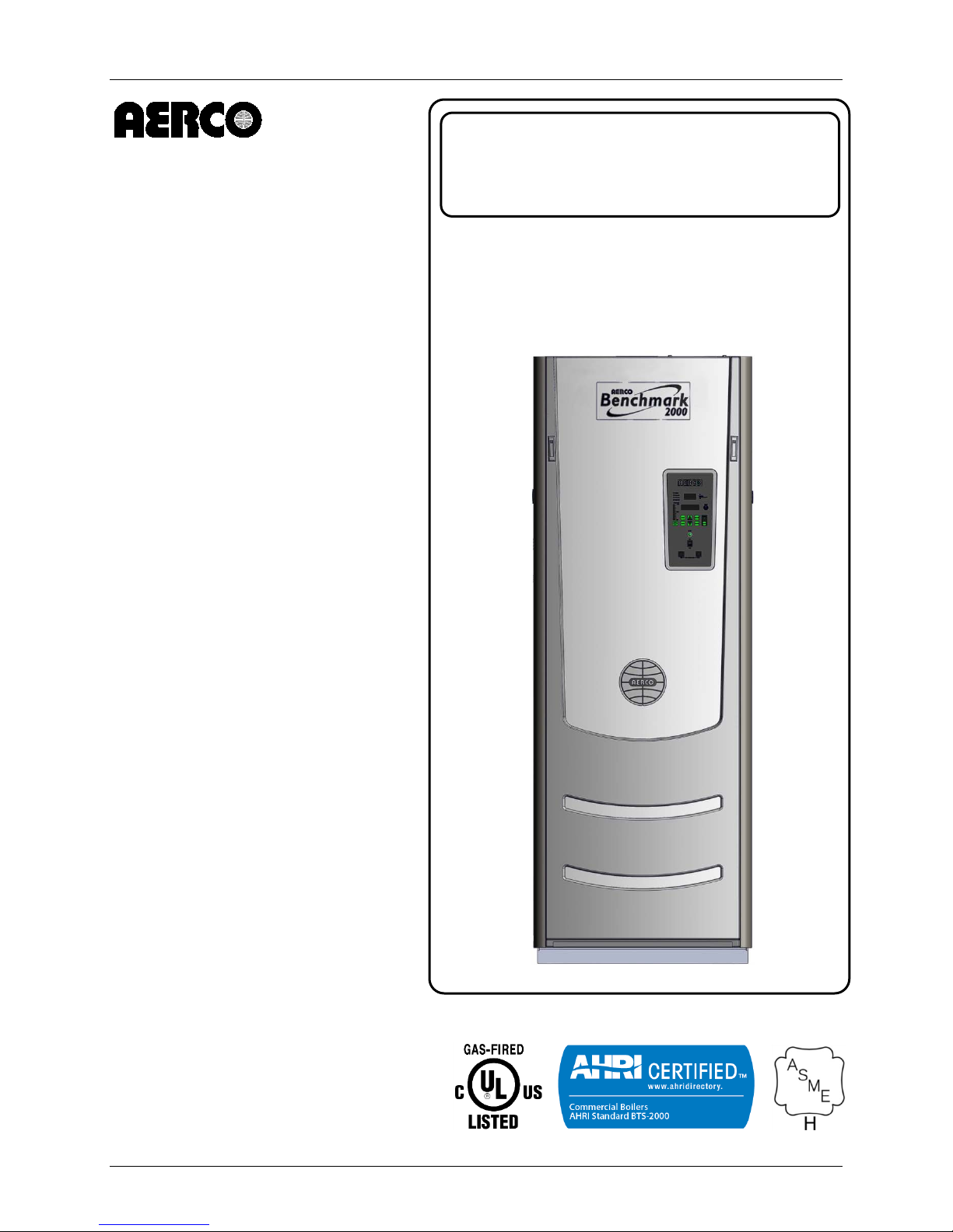
Benchmark 1500 - 2000 Boilers
BENCHMARK
Installation, Operation & Maintenance Manual (IOMM)
Natural Gas Modulating
& Condensing Hot Water
USER MANUAL
Installation, Opera ti on and Maintenance
Boiler Models:
• BMK 1500
• BMK 2000
Applicable to Serial Numbers:
G-13-1690 and Above
1500 / 2000
Gas-Fired Boilers
Latest Update: 11/21/2013
OMM-0097_0C AERCO International, Inc. • 100 Oritani Dr. • Blauvelt, NY 10913 Page 1 of 184
GF-142 Ph.: 800-526-0288
Page 2

Benchmark 1500 - 2000 Boilers
Installation, Operation & Maintenance Manual (IOMM)
Technical Support
(Mon-Fri, 8am-5pm EST)
1-800-526-0288
www.aerco.com
The information containe d in this manual is subject to c hange without notice from AERCO Inter national,
Inc. AERCO makes no warranty of any kind with respect to this material, including but not limited to
implied warranties of merchantabilit y and fitness for a par ticular application. AERCO International is not
liable for errors appearing in this manual. Nor for incidental or consequential damages occurring in
connection with the furnishing, performance, or use of this material.
Page 2 of 184 AERCO International, Inc. • 100 Oritani Dr. • Blauvelt, NY 10913 OMM-0097_0C
Ph.: 800-526-0288 GF-142
Disclaimer
Page 3

Benchmark 1500 - 2000 Boilers
Installation, Operation & Maintenance Manual (IOMM)
TABLE OF CONTENTS
FOREWORD 7
CHAPTER 1. SAFETY PRECAUTIONS ......................................................................................... 11
1.1 WARNINGS & CAUTIONS ................................................................................................................... 11
1.2 EMERGENC Y SHUT D OWN ................................................................................................................. 12
1.3 PROLONGED SHUTDOWN ................................................................................................................. 12
CHAPTER 2. INSTALLATION ........................................................................................................ 15
2.1 INTRODUCTION ................................................................................................................................... 15
2.2 RECEIVING THE UNIT ......................................................................................................................... 15
2.3 UNPACKING ......................................................................................................................................... 15
2.4 SITE PREPARATION ........................................................................................................................... 16
2.4.1 Installation Clearances .................................................................................................................................... 16
2.4.2 Setting the Unit ............................................................................................................................................... 17
2.5 SUPPLY AND RETURN PIPING .......................................................................................................... 19
2.6 PRESSURE RELIEF VALVE INSTALLATION ..................................................................................... 19
2.7 CONDENSATE DRAIN & PIPING ........................................................................................................ 20
2.8 GAS SUPPLY PIPIN G .......................................................................................................................... 22
2.8.1 Gas Supply Specifications. .............................................................................................................................. 22
2.8.2 Manual Gas Shutoff Valve .............................................................................................................................. 22
2.8.3 External Gas Supply Regulator ........................................................................................................................ 23
2.9 AC ELECTRICAL POWER WIRING ..................................................................................................... 24
2.9.1 Electrical Power Requirements ....................................................................................................................... 25
2.10 FIELD CONTROL WIRING ................................................................................................................. 26
2.10.1 Outdoor Air In (OUT) & Air Sensor Common (COM) .................................................................................... 27
2.10.2 COMBUSTION AIR Terminal .......................................................................................................................... 28
2.10.3 O2 SENSOR (O2+ & O2-) ................................................................................................................................ 28
2.10.4 SPARK SIGNAL (FLW+ & FLW-) ...................................................................................................................... 28
2.10.5 Analog In (+ & -) ............................................................................................................................................ 28
2.10.6 B.M.S. (PWM) In (BMS+ & BMS-) .................................................................................................................. 28
2.10.7 Shield (SHLD & SHLD) .................................................................................................................................... 28
2.10.8 Analog Output (+ & -) ................................................................................................................................... 28
2.10.9 RS-485 Comm (+, GND, & -) .......................................................................................................................... 29
2.10.10 RS-232 Comm (TxD & RxD) ......................................................................................................................... 29
2.10.11 VFD/Blower (0-10 & AGND) ........................................................................................................................ 29
2.10.12 Interlocks .................................................................................................................................................... 29
2.10.13 Fault Relay (NC, COM, & NO) ...................................................................................................................... 30
2.10.14 Auxiliary Relay Contacts (NC, COM, & NO) ................................................................................................. 30
2.11 FLUE GAS VENT INSTALLATION ..................................................................................................... 30
2.12 COMBUSTION AIR ............................................................................................................................. 30
2.12.1 Combustion From Outside the Building ....................................................................................................... 31
2.12.2 Combustion Air from Inside the Building ...................................................................................................... 31
2.13 DUCTED COMBUSTION AIR ............................................................................................................. 31
CHAPTER 3. OPERATION .............................................................................................................. 33
3.1 INTRODUCTION ................................................................................................................................... 33
3.2 CONTROL PANEL DESCRIPTION ...................................................................................................... 33
3.3 CONTROL PANEL MENUS .................................................................................................................. 37
3.3.1 Menu Processing Procedure ........................................................................................................................... 37
3.4 OPERATING MENU ............................................................................................................................. 39
3.5 SETUP MENU ....................................................................................................................................... 39
OMM-0097_0C AERCO International, Inc. • 100 Oritani Dr. • Blauvelt, NY 10913 Page 3 of 184
GF-142 Ph.: 800-526-0288
Page 4

Benchmark 1500 - 2000 Boilers
3.6 CONFIGURATION MENU .................................................................................................................... 40
3.7 TUNING MENU ..................................................................................................................................... 42
3.8 COMBUSTION CAL MENU .................................................................................................................. 43
3.9 START SEQUENCE ............................................................................................................................. 43
3.10 START/STOP LEVELS ....................................................................................................................... 47
CHAPTER 4. INITIAL START-UP .................................................................................................. 49
4.1 INITIAL START-UP REQUIREMENTS ................................................................................................. 49
4.2 TOOLS AND INSTRUMENTATION FOR COMBUSTION CALIBRATION .......................................... 49
4.2.1 Required Tools & Instrumentation ................................................................................................................. 50
4.2.2 Installing Gas Supply Manometer ................................................................................................................... 50
4.2.3 Accessing the Analyzer Probe Port ................................................................................................................. 51
4.3 NATURAL GAS COMBUSTION CALIBRATION .................................................................................. 52
4.3.1 BMK 1500 Natural Gas Combustion Calibration .................................................... 52
4.3.2 BMK 2000 Natural Gas Combustion Calibration ..................................................... 56
4.4 REASSEMBLY ...................................................................................................................................... 58
4.5 OVER-TEMPERATURE LIMIT SWITCHES ......................................................................................... 59
4.5.1 Digital Alarm Switch Checks and Adjustments ............................................................................................... 59
CHAPTER 5. MODE OF OPERATION ........................................................................................... 61
5.1 INTRODUCTION ................................................................................................................................... 61
5.2 INDOOR/OUTDOOR RESET MODE ................................................................................................... 61
5.2.1 Reset Ratio ...................................................................................................................................................... 61
5.2.2 Building Reference Temperature .................................................................................................................... 61
5.2.3 Outdoor Air Temperature Sensor Installation ................................................................................................ 61
5.2.4 Indoor/Outdoor Startup ................................................................................................................................. 61
5.3 CONSTANT SETPOINT MODE ........................................................................................................... 62
5.3.1 Setting the Setpoint ........................................................................................................................................ 62
5.4 REMOTE SETPOINT MODES ............................................................................................................. 63
5.4.1 Remote Setpoint Field Wiring ......................................................................................................................... 63
5.4.2 Remote Setpoint Startup ................................................................................................................................ 64
5.5 DIRECT DRIVE MODES....................................................................................................................... 64
5.5.1 Direct Drive Field Wiring ................................................................................................................................. 65
5.5.2 Direct Drive Startup ........................................................................................................................................ 65
5.6 AERCO CONTROL SYSTEM (ACS) .................................................................................................... 65
5.6.1 ACS External Field Wiring................................................................................................................................ 65
5.6.2 ACS Setup and Startup .................................................................................................................................... 66
5.7 COMBINATION CONTROL SYSTEM (CCS) ....................................................................................... 66
5.7.1 Combination Control System Field Wiring ...................................................................................................... 67
5.7.2 Combination Control System Setup and Startup ............................................................................................ 67
CHAPTER 6. SAFETY DEVICE TESTING ..................................................................................... 69
6.1 TESTING OF SAFETY DEVI CE S ......................................................................................................... 69
6.2 LOW GAS PRESSURE FAULT TEST .................................................................................................. 70
6.3 HIGH GAS PRESSURE TEST ............................................................................................................. 71
6.4 LOW WATER LEVEL FAULT TEST ..................................................................................................... 72
6.5 WATER TEMPERATURE FAULT TEST .............................................................................................. 73
6.6 INTERLOCK TESTS ............................................................................................................................. 74
6.6.1 Remote Interlock Test..................................................................................................................................... 74
6.6.2 Delayed Interlock Test .................................................................................................................................... 74
6.7 FLAME FAULT TESTS ......................................................................................................................... 75
6.8 AIR FLOW FAULT TESTS .................................................................................................................... 77
6.9 SSOV PROOF OF CLOSURE SWITCH ............................................................................................... 78
Installation, Operation & Maintenance Manual (IOMM)
Page 4 of 184 AERCO International, Inc. • 100 Oritani Dr. • Blauvelt, NY 10913 OMM-0097_0C
Ph.: 800-526-0288 GF-142
Page 5

Benchmark 1500 - 2000 Boilers
6.10 PURGE SWITCH OPEN DURING PURGE ........................................................................................ 79
6.11 IGNITION SWITCH OPEN DURING IGNITION ................................................................................. 80
6.12 SAFETY PRESSURE RELIEF VALVE TEST ..................................................................................... 81
CHAPTER 7. MAINTENANCE ......................................................................................................... 83
7.1 MAINTENANCE SCHEDULE ............................................................................................................... 83
7.2 IGNITER-INJECTOR ............................................................................................................................ 84
7.3 FLAME DETECTOR ............................................................................................................................. 86
7.4 O2 SENSOR 87
7.5 SAFETY DEVIC E TESTING ................................................................................................................. 87
7.6 BURNER ASSEMB LY INSPECTION ................................................................................................... 88
7.7 CONDENSATE DRAIN TRAP .............................................................................................................. 92
7.8 AIR FILTER CLEANING & REPLACEMENT ........................................................................................ 93
7.9 SHUTTING THE BOILER DOWN FOR AN EXTENDED PERIOD OF TIME ....................................... 94
7.10 PLACING THE BOI L E R BACK IN SER VI C E AF TER A PRO LO N GED SHUTDOWN ....................... 94
CHAPTER 8. TROUBLESHOOTING GUIDE ................................................................................ 95
8.1 INTRODUCTION ................................................................................................................................... 95
8.2 ADDITIONAL FAULTS WITHOUT SPECIFIC FAULT MESSAGES .................................................. 107
CHAPTER 9. RS-232 COMMUNICATION................................................................................. 109
9.1 INTRODUCTION ................................................................................................................................. 109
9.1.1 Acquiring the PuTTY Application .................................................................................................................. 109
9.1.2 Running a Command on a Remote Machine Using PuTTY ........................................................................... 110
9.2 RS-232 COMMUNICATION SETUP ................................................................................................... 111
9.3 MENU PROCESSING UTILIZING RS-232 COMMUNICATION ........................................................ 111
9.4 DATA LOGGING ................................................................................................................................. 112
9.4.1 Fault Log ....................................................................................................................................................... 112
9.4.2 Operation Time Log ...................................................................................................................................... 113
9.4.3 Sensor Log ..................................................................................................................................................... 114
APPENDIX A: BOILER MENU ITEM DESCRIPTIONS ............................................................. 115
APPENDIX B: STARTUP, STATUS & DISPLAY MESSAGES .................................................. 121
APPENDIX C: SENSOR RESISTANCE/VOLTAGE CHART ...................................................... 125
APPENDIX D: BOILER DEFAULT SETTINGS ............................................................................ 127
APPENDIX E: RECOMMENDED PERIODIC TESTING ............................................................ 129
APPENDIX F: INDOOR/OUTDOOR RESET RATIO CHARTS ............................................... 131
APPENDIX G: DIMENSIONAL AND CLEARANCE DRAWINGS ............................................. 135
APPENDIX H: PART DRAWINGS ................................................................................................. 139
APPENDIX I: WIRING DIAGRAMS ............................................................................................. 151
APPENDIX J: PIPING DRAWINGS .............................................................................................. 171
APPENDIX K: C-MORE CONTROL PANEL VIEWS ................................................................... 177
APPENDIX L: RECOMMENDED SPARES ................................................................................... 179
Installation, Operation & Maintenance Manual (IOMM)
OMM-0097_0C AERCO International, Inc. • 100 Oritani Dr. • Blauvelt, NY 10913 Page 5 of 184
GF-142 Ph.: 800-526-0288
Page 6

Benchmark 1500 - 2000 Boilers
Installation, Operation & Maintenance Manual (IOMM)
(This Page Is Intentionally Blank)
Page 6 of 184 AERCO International, Inc. • 100 Oritani Dr. • Blauvelt, NY 10913 OMM-0097_0C
Ph.: 800-526-0288 GF-142
Page 7
Benchmark 1500 - 2000 Boilers
Minimum
Maximum
Minimum
Maximum
FORWARD
FOREWORD
The AERCO Benchmark (BMK) 1500 and 2000 MBH boilers are modulating and condensing
units. They represent a true industry advance that meets the needs of today's energy and
environmental concerns. Designed for application in any closed loop hydronic system, the
Benchmark's modulating capability relates energy input directly to fluctuating system loads. The
turn down ratios for these boilers is 20:1. These BMK models provide extrem ely high efficiency
operation and are ideally suited for modern low tem perature, as well as, conventional heating
systems.
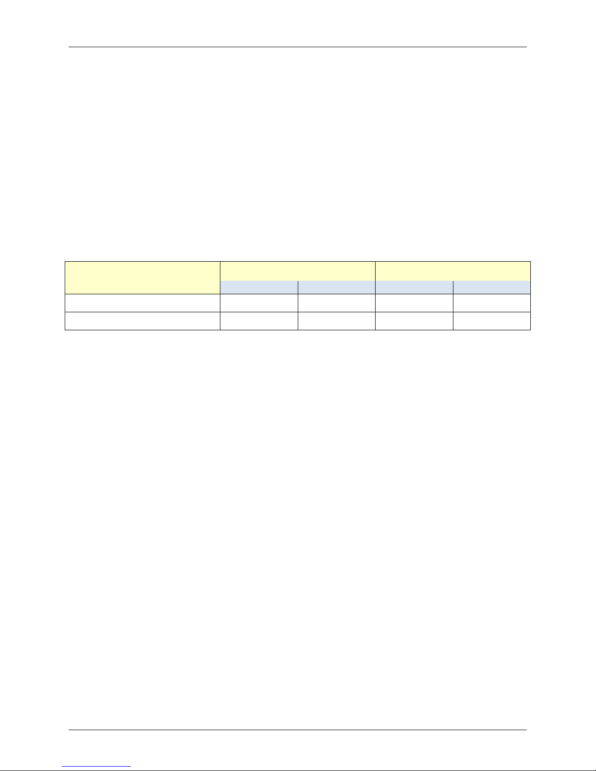
The Benchmark Model BMK 1500 and BMK 2000 boilers operate within the following input and
output ranges:
Benchmark Model
BMK 1500 75,000 1,500,000 64,500 1,395,000
Input Range (BTU/hr.) Output Range (BTU/hr.)
BMK 2000 100,000 2,000,000 86,000 1,860,000
The output of the boiler is a function of the unit’s firing rate (valve position) and return water
temperature.
When installed and operated in accordance with this Instruction Manual, these boilers comply
with the NOx emission standards outlined in:
South Coast Air Quality Management Distric t ( SCAQ MD), Rule 1 14 6.2
Whether used in singular or modular arrangements, the BMK 1500 and BMK 2000 offer the
maximum venting flexibility with minimum installation space requirements. These boilers are
Category II, III and IV, positive pressure appliances. Single and/or multiple breeched units are
capable of operation in the following vent configurations:
Conventional, Vertical
Conventional, Sidewall
Conventional, Direct Vent, Vertical
Sealed, Direct Vent, Horizontal
These boilers are capable of being vented utilizing Polypropylene and AL29-4C vent systems.
The Benchmark's advanced electronics are available in several selectable modes of operation
offering the most efficient operating methods and energy management system integration.
Unless otherwise specified, all descriptions and procedures provided in this
Installation, Operation & Maintenance Manual apply to the Benchmark
series of boiler.
OMM-0097_0C AERCO International, Inc. • 100 Oritani Dr. • Blauvelt, NY 10913 Page 7 of 184
GF-142 Ph.: 800-526-0288
IMPORTANT
Page 8

Benchmark 1500 - 2000 Boilers
ASME
American Society of Mechanical Engineers
(see below)
or simply the number of distinct symbol changes
Cal.
Calibration
Double Block and Bleed. Used to define boiler gas trains
containing 2 Safety Shutoff Valves (SSOVs) and a solenoid
Energy Management System; often used interchangeably with
FORWARD
Phrases, Abbreviations and Acronyms
Phrase, Abbreviation or
Acronym
Meaning
A (Amp) Ampere
ACS AERCO Control System
ADDR Address
AGND Anal og Ground
ALRM Alarm
AUX Auxiliary
BAS
Building Automation System, often used interchangeably with EMS
Symbol rate,
Baud Rate
(signaling events) transmitted per second. It is not equal to bits per
second, unless each symbol is 1 bit long.
BMK Benchmark series boilers
BMS or BMS II AERCO Boiler Management Systems
BLDG (Bldg) Building
BTU
British Thermal Unit. A unit of energy approximately equal to the
heat required to raise 1 pound of water 1° F.
CCP Combustion Control Panel
C-More Controller
(or Control Box)
A control system developed by AERCO and currently used in all
Benchmark, Innovation and KC1000 Series product lines.
CO Carbon Monoxide
COMM (Comm) Communication
CNTL Control
DBB
operated vent valve. Also known as IRI gas trains(see below)
DIP Dual In-Line Package
EMS
BAS
FM Factory Mutual. Used to define boiler gas trains.
GND Ground
HDR Header
HX Heat Exchang er
Hz Hertz (Cycles Per Second)
I.D. Inside Diameter
IGN Ignition
Page 8 of 184 AERCO International, Inc. • 100 Oritani Dr. • Blauvelt, NY 10913 OMM-0097_0C
Ph.: 800-526-0288 GF-142
Page 9

Benchmark 1500 - 2000 Boilers
Phrase, Abbreviation or
Acronym
FORWARD
Phrases, Abbreviations and Acronyms – Continued
Meaning
IGST Board Ignition/Stepper Board contained in C-More Control Box
INTLK (INTL’K) Interlock
I/O Input/Output
I/O Box
IP Internet Protocol
IRI
ISO Isolated
LED Light Emitting Diode
LN Low NOx
MA (mA) Milliampere (0.001 Amp), one thousandth of an amp
MAX (Max) Maximum
MIN (Min) Minimum
Modbus®
NC (N.C.) Normally Closed
NO (N.O.) Normally Open
NOx Nitrogen Oxide
NPT National Pipe Thread
O2 Oxygen
O.D. Outside Diameter
PMC Board
PPM Parts Per Million
PTP Point-to-Point (usually over RS-232 networks)
PWM Pulse Width Modulation
REF (Ref) Reference
RES. Resistive
RS-232
(or EIA-232)
RS-422
(or EIA-422)
RS-485
(or EIA-485)
RTN (Rtn) Return
SETPT (Setpt) Setpoint Temperature
SHLD (Shld) Shield
Input/Output (I/O) Box currently used on Benchmark, Innovation and
KC1000 Series products
Industrial Risk Insurers. A now discontinued code used to define gas
trains containing two SSOVs and a solenoid operated vent valve.
A serial, half-duplex data transmission protocol developed by AEG
Modicon
A Primary Micro-Controller (PMC) board is contained in the C-More
Control Box used on all Benchmark units.
A standard for serial, full-duplex (FDX) transmission of data based on the
RS-232 Standard
A standard for serial, full-duplex (FDX) transmission of data based on the
RS-422 Standard
A standard for ser ial, half-duplex (HDX) trans mission of data based on
the RS-485 Standard
OMM-0097_0C AERCO International, Inc. • 100 Oritani Dr. • Blauvelt, NY 10913 Page 9 of 184
GF-142 Ph.: 800-526-0288
Page 10

Benchmark 1500 - 2000 Boilers
Phrase, Abbreviation or
Acronym
TEMP (Temp)
Temperature
order to prevent reflections that may cause invalid data in the
VDC
Volts, Direct Current
W.C.
Water Column (W.C.)
FORWARD
Phrases, Abbreviations and Acronyms – Continued
Meaning
SSOV Safety Shut Off Valve
A resistor placed at each end of a dais y-chain or multi-drop network in
Terminating Resistor
communication
uA Microamp (0.000001 amp), one millionth of an amp
VAC Volts, Alternating Current
VFD Vacuum Fluorescent Display, or Variable Frequency Drive
W Watt
Page 10 of 184 AERCO International, Inc. • 100 Oritani Dr. • Blauvelt, NY 10913 OMM-0097_0C
Ph.: 800-526-0288 GF-142
Page 11
Benchmark 1500 - 2000 Boilers
WARNING
WARNING
WARNING
WARNING
CHAPTER 1 – SAFETY PRECAUTIONS
CHAPTER 1. SAFET Y PRECAUTIONS
1.1 WARNINGS & CAUTIONS
Installers and operating personnel MUST, at all times, observe all safety regulations. The
following warnings and cautions are general and must be given the same attention as specific
precautions included in these instructions. In addition to all the requirements included in this
AERCO Instruction Manual, the installation of units MUST conform with local building codes, or,
in the absence of local codes, ANSI Z223.1 (National Fuel Gas Code Publication No. NFPA-54)
for gas-fired boilers and ANSI/NFPASB for LP gas-fired boilers. Where applicable, the
equipment shall be installed in accordance with the current Installation Code for Gas Burning
Appliances and Equipment, CSA B149.1, and applicable Provincial regulations for the class;
which should be carefully followed in all cases. Authorities having jurisdiction should be
consulted before installations are made.
See pages 13 and 14 for important information regarding installation of units within the
Commonwealth of Massachusetts.
IMPORTANT
This Instruction Manual is an integral part of the product and must be
maintained in legible condition. It must be given to the user by the installer
and kept in a safe place for future reference.
DO NOT USE MATCHES, CANDLES, FLAMES, OR OTHER SOURCES
OF IGNITION TO CHECK FOR GAS LEAKS.
FLUIDS UNDER PRESSURE MAY CAUSE INJURY TO PERSONNEL OR
DAMAGE TO EQUIPMENT WHEN RELEASED. BE SURE TO SHUT OFF
ALL INCOMING AND OUTGOING WATER SHUTOFF VALVES.
CAREFULLY DECREASE ALL TRAPPED PRESSURES TO ZERO
BEFORE PERFORMING MAINTENANCE.
BEFORE ATTEMPTING TO PERFORM ANY MAINTENANCE ON THE
UNIT, SHUT OFF ALL GAS AND ELECTRICAL INPUTS TO THE UNIT.
THE EXHAUST VENT PIPE OF THE UNIT OPERATES UNDER A
POSITIVE PRESSURE AND THEREFORE MUST BE COMPLETELY
SEALED TO PREVENT LEAKAGE OF COMBUSTION PRODUCTS I NTO
LIVING SPACES.
WARNING
ELECTRICAL VOLTAGES UP TO 480 VAC MAY BE USED IN THIS
EQUIPMENT. THEREFO RE THE COVER ON THE UNI T’S POWER BOX
(LOCATED BEHIND THE FRONT PANEL DOOR) MUST BE INSTALLED
AT ALL TIMES, EXCEPT DURING MAINTENANCE AND SERVICING.
OMM-0097_0C AERCO International, Inc. • 100 Oritani Dr. • Blauvelt, NY 10913 Page 11 of 184
GF-142 Ph.: 800-526-0288
Page 12
Benchmark 1500 - 2000 Boilers
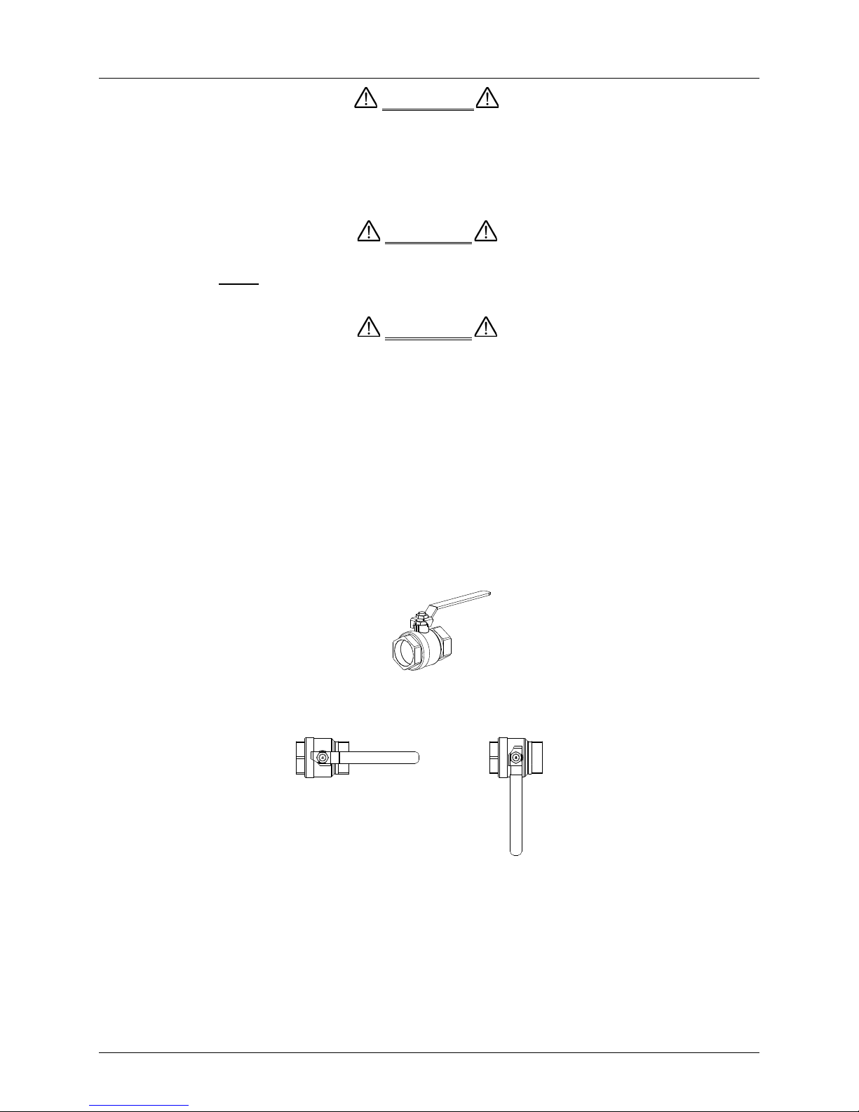
MANUAL GAS SHUTOFF VALVE
VALVE OPEN
VALVE CLOSED
WARNING
CAUTION
CAUTION
CHAPTER 1 – SAFETY PRECAUTIONS
A THREE-POLE SWITCH MUST BE INSTALLED ON THE ELECTRICAL
SUPPLY LINE OF THE UNIT. T HE SWIT CH MUST BE INSTALLED IN AN
EASILY ACCESSIBLE POSITION TO QUICKLY AND SAFELY
DISCONNECT ELECTRICAL SERVICE. DO NOT AFFIX SWITCH TO
UNIT SHEET METAL ENCLOSURES.
Many soaps used for gas pipe leak testing are corrosive to metals. The
piping must be rinsed thoroughly with clean water after leak checks have
been completed.
DO NOT use t his boiler if any part has been under water. Call a qualified
service technician to inspect and replace any part that has been under
water.
1.2 EMERGENCY SHUTDOWN
If overheating occurs or the gas supply fails to shut off, close the manual gas shutoff valve
(Figure 1-1) located external to the unit.
Figure 1-1: Manual Gas Shutoff Valve
1.3 PROLONGED SHUTDOWN
After prolonged shutdown, it is recommended that the startup procedures in Chapter 4 and the
safety device test procedures in Chapter 6 of this manual be performed, to verify all systemoperating parameters. If there is an emergency, turn off the electrical power supply to the
AERCO boiler and close the manual gas valve located upstream the unit. The installer must
identify the emergency shut-off device.
NOTE
The Installer must identify and indicate the location of the
emergency shutdown manual gas valve to operating personnel.
Page 12 of 184 AERCO International, Inc. • 100 Oritani Dr. • Blauvelt, NY 10913 OMM-0097_0C
Ph.: 800-526-0288 GF-142
Page 13

Benchmark 1500 - 2000 Boilers
CHAPTER 1 – SAFETY PRECAUTIONS
IMPORTANT – FOR MASSACHUSETTS INSTALLATIONS
Boiler Installations within the Commonwealth of Massachusetts must
conform to the following requirements:
• Boiler must be installed by a plumber or a gas fitter who is licensed
within the Commonwealth of Massachusetts.
• Prior to unit operation, the complete gas train and all connections must
be leak tested using a non-corrosive soap.
• The vent termination must be located a m inimum of 4 feet above grade
level. If side-wall venting is used, the installation must conform to the
following requirem ent s extracted from 248 CMR 5.08 (2):
(a) For all side wall horizontally vented gas fueled equipment installed in every dwelling,
building or structure used in whole or in part for residential purposes, including those owned or
operated by the Commonwealth and where the side wall exhaust vent termination is less than
seven (7) feet above finished grade in the area of the venting, including but not limited to decks
and porches, the following requirements shall be satisfied:
1. INSTALLATION OF CARBO N MONOXIDE DETECTORS. At the time of installation of
the side wall horizontal vented gas fueled equipment, the installing plumber or gasfitter shall
observe that a hard wired carbon monoxide detector with an alarm and battery back-up is
installed on the floor level where the gas equipment is to be installed. In addition, the
installing plumber or gasfitter shall observe that a battery operated or hard wired carbon
monoxide detector with an alarm is installed on each additional level of the dwelling, building
or structure served by the side wall horizontal vented gas fueled equipment. It shall be the
responsibility of the property owner to secure the services of qualified licensed professionals
for the installation of hard wired carbon monoxide detectors.
a. In the event that the side wall horizontally vented gas fueled eq uipment is installed in a
crawl space or an attic, the hard wired carbon monoxide detector with alarm and battery
back-up may be installed on the next adjacent floor level.
b. In the event that the requirements of this subdivision can not be met at the time of
completion of installation, the owner shall have a period of thirty (30) days to comply with
the above requirements; provided, however, that during said thirty (30) day period, a
battery operated carbon monoxide detector with an alarm shall be installed.
2. APPROVED CARBON MONOXIDE DETECTORS. Each carbon monoxide detector as
required in accordance with the above provisions shall comply with NFPA 720 and be
ANSI/UL 2034 listed and IAS certified.
3. SIGNAGE. A metal or plastic identification plate shall be permanently mounted to the
exterior of the building at a minimum height of eight ( 8) feet above grade directly in line with
the exhaust vent terminal for the horizontally vented gas fueled heating appliance or
equipment. The sign shall read, in print size no less than one-half (1/2) inch in size, "GAS
VENT DIRECTLY BELOW. KEEP CLEAR OF ALL OBSTRUC TIONS".
4. INSPECTION. The state or local gas inspector of the side wall horizontally vented gas
fueled equipment shall not approve the installation unless, upon inspection, the inspector
observes carbon monoxide detectors and signage installed in accordance with the
provisions of 248 CMR 5.08(2)(a)1 through 4.
OMM-0097_0C AERCO International, Inc. • 100 Oritani Dr. • Blauvelt, NY 10913 Page 13 of 184
GF-142 Ph.: 800-526-0288
Page 14

Benchmark 1500 - 2000 Boilers
CHAPTER 1 – SAFETY PRECAUTIONS
(b) EXEMPTIONS: The following equipment is exempt from 248 CMR 5.08(2)(a)1 through 4:
1. The equipment listed in Chapter 10 entitled "Equipment Not Required To Be Vented" in
the most current edition of NFPA 54 as adopted by the Board; and
2. Product Approved side wall horizontally vented gas fueled equipment installed in a room
or structure separate from the dwelling, building or structure used in whole or in part for
residential purposes.
(c) MANUFACTURER REQUIREMENTS - GAS EQUIPMENT VENTING SYSTEM
PROVIDED. When the manufacturer of Product Approved side wall horizontally vented gas
equipment provides a venting system design or venting system components with the equipment,
the instructions provided by the manufacturer for installation of the equipment and the venting
system shall include:
1. Detailed instructions for the installation of the venting system design or the venting
system components; and
2. A complete parts list for the venting system design or venting system.
(d) MANUFACTURER REQUIREMENTS - GAS EQUIPMENT VENTING SYSTEM NOT
PROVIDED. When the manufacturer of a Product Approved side wall horizontally vented gas
fueled equipment does not provide the parts for venting the flue gases, but identifies "special
venting systems", the following requirements shall be satisfied by the manufacturer:
1. The referenced "special venting system" instructions shall be included with the appliance
or equipment installation instructions; and
2. The "special venting systems" shall be Product Approved by the Board, and the
instructions for that system shall include a parts list and detailed installation instructions.
(e) A copy of all installation instructions for all Product Approved side wall horizontally vented
gas fueled equipment, all venting instructions, all parts lists for venting instructions, and/or all
venting design instructions shall remain with the appliance or equipment at the completion of the
installation.
____________________________________________________________________________
[End of Extracted Information From 248 CMR 5.08 (2)]
Page 14 of 184 AERCO International, Inc. • 100 Oritani Dr. • Blauvelt, NY 10913 OMM-0097_0C
Ph.: 800-526-0288 GF-142
Page 15

Benchmark 1500 - 2000 Boilers
CHAPTER 2 – INSTALLATION
CHAPTER 2. INSTALLATION
2.1 INTRODUCTION
This Chapter provides the descriptions and procedures necessary to unpack, inspect and install
the AERCO Benchmark Boiler Model BMK 1500 and BMK 2000.
2.2 RECEIVING THE UNIT
Each Benchmark Boiler System is shipped as a single crated unit. The shipping weight for these
BMK models is approximately 1800 pounds. The unit must be moved with the proper rigging
equipment for safety and to avoid equipment damage. The unit should be completely inspected
for evidence of shipping damage and shipment completeness at the time of receipt from the
carrier and before the bill of lading is signed.
NOTE
AERCO is not responsible for lost or damaged freight. Each unit
has a Tip-N-Tell indicator on the outside of the crate. This
indicates if the unit has been turned on its side during shipment. If
the Tip-N-Tell indicator is tripped, do not sign for the shipment.
Note the information on the carrier’s paperwork and request a
freight claim and inspection by a claims adjuster before
proceeding. Any other visual damage to the packaging materials
should also be made clear to the delivering carrier.
2.3 UNPACKING
Carefully unpack the unit taking care not to damage the unit enclosure when cutting away
packaging materials
After unpacking, a close inspection of the unit should be made to ensure that there is no
evidence of damage not indicated by the Tip-N-Tell indicator. The freight carrier should be
notified immediately if any damage is detected.
The following accessories come standard with each unit and are either packed separately within
the unit’s shipping container or are factory installed on the unit:
• Pressure/Temperature Gauge
• ASME Pressure Relief Valve
• Condensate Drain Trap (part no. 24060)
• 2” Gas Supply Shutoff Valve
When optional accessories are ordered, they may be packed within the unit’s shipping
container, factory installed on the unit, or packed and shipped in a separate container. Any
standard or optional accessories shipped loose should be identified and stored in a safe place
until ready for installation or use.
OMM-0097_0C AERCO International, Inc. • 100 Oritani Dr. • Blauvelt, NY 10913 Page 15 of 184
GF-142 Ph.: 800-526-0288
Page 16
Benchmark 1500 - 2000 Boilers
CHAPTER 2 – INSTALLATION
2.4 SITE PREPARATION
Ensure that the site selected for installation of the Benchmark 1500/2000 Boiler includes:
• Access to AC Input Power at 120 VAC, Single-Phase, 60 Hz @ 20 Amps
• Access to Natural Gas line at a minimum pressure of 8 inches W.C. at gas flow for
1,500,000 BTU/hr energy input for the BMK 1500 OR 2,000, 000 BTU/hr energy input for
the BMK 2000.
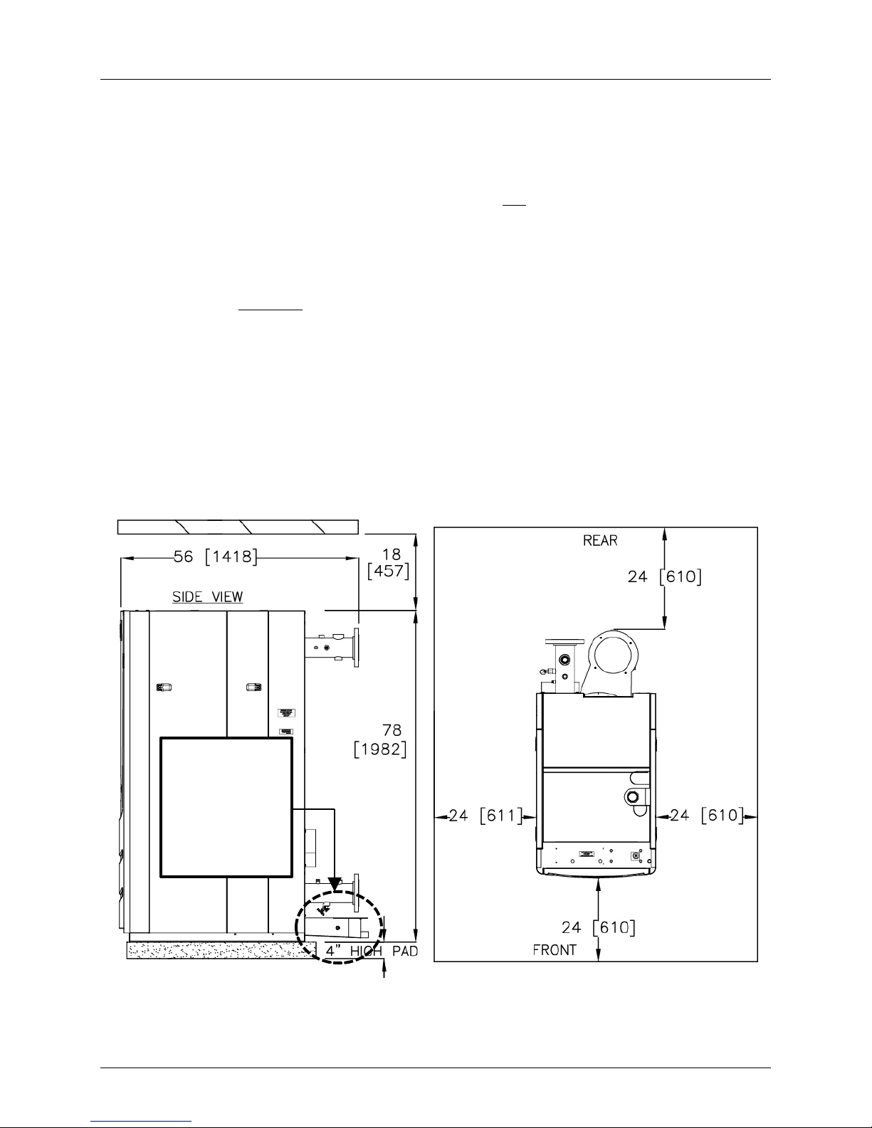
2.4.1 Installation Clearances
The Benchmark Model 1500 and 2000 are packaged in an enclosure having identical exterior
dimensions. The unit must be installed with the prescribed clearances for service as shown in
Figure 2-1a. The minimum clearance dimensions, required by AERCO, are listed below.
However, if Local Building Codes require additional clearances, these codes shall supersede
AERCO’s requirements. Minimum acceptable clearances required are as follows:
• Sides: 24 inches
• Front : 24 inches
• Rear: 24 inches
• Top: 18 inches
All gas piping, water piping and electrical conduit or cable must be arr anged so that they do not
interfere with the removal of any panels, or inhibit service or maintenance of the unit.
NOTE
Ensure that
condensate
assembly is not
located over the
housekeeping
pad.
Figure 2-1a: Benchmark Boiler Model 1500/2000 Clearances
Page 16 of 184 AERCO International, Inc. • 100 Oritani Dr. • Blauvelt, NY 10913 OMM-0097_0C
Ph.: 800-526-0288 GF-142
Page 17
Benchmark 1500 - 2000 Boilers
CAUTION
WARNING
CHAPTER 2 – INSTALLATION
WARNING
KEEP THE UNIT AREA CLEAR AND FREE FR OM ALL COMBUSTIBLE
MATERIALS AND FLAMMABLE VAPORS OR LIQUIDS
.
While packaged in the shipping container, the unit must be moved by pallet
jack or forklift from the FRONT ONLY.
FOR MASSACHUSSETTS ONLY:
For Massachusetts installations, the unit must be installed by a plumber or
gas-fitter licensed within the Commonwealth of Massachusetts. I n addition,
the installation must comply with all requirements specified in Chapter 1
(Safety Precautions), pages 11 and 12.
2.4.2 Setting the Unit
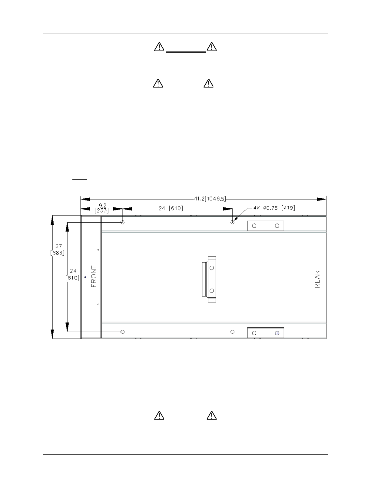
The unit must be installed on a 4 inch to 6 inch thick housekeeping pad to ensure proper
condensate drainage. If anchoring the unit, refer to Figure 2-1b for anchor locations.
Figure 2-1b: Benchmark 1500/2000 Anchor Bolt Locations
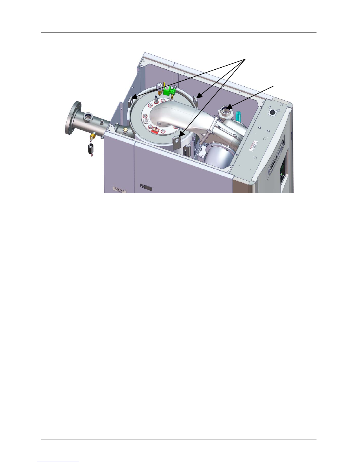
A total of 3 lifting lugs are provided at the top of the primary heat exchanger as shown in Figure
2-2. Remove the front top panel from the unit to provide access to the lifting tabs.
Remove the four (4) lag screws securing the unit to the shipping skid. Lift the unit off the
shipping skid and position it on the 4 inch to 6 inch housek eeping concrete pad (requir ed) in the
desired location.
WHEN LIFTING OR MOVING THE BOILER, DO NOT ATTEMPT
TO MANIPULATE THE BOILER USING THE GAS TRAIN OR
BLOWER.
OMM-0097_0C AERCO International, Inc. • 100 Oritani Dr. • Blauvelt, NY 10913 Page 17 of 184
GF-142 Ph.: 800-526-0288
Page 18
Benchmark 1500 - 2000 Boilers
CHAPTER 2 – INSTALLATION
LIFTING LUGS
(3 POSITIONS)
2” GAS INLET
Figure 2-2: Boiler Lifting Provisions
In multiple unit installations, it is important to plan the position of each unit in advance. Sufficient
space for piping connections and future service/maintenance requirements must also be taken
into consideration. All piping must include ample provisions for expansion.
If installing a Combination Control Panel (CCP) system, it is important to identify the
Combination Mode Boilers in advance and place them in the proper physical location. Refer to
Chapter 5 for information on Combination Mode Boilers.
Page 18 of 184 AERCO International, Inc. • 100 Oritani Dr. • Blauvelt, NY 10913 OMM-0097_0C
Ph.: 800-526-0288 GF-142
Page 19
Benchmark 1500 - 2000 Boilers
BOILER HOT
(SUPPLY)
EXHAUST
MANIFOLD
CONDENSATE
DRAIN PORT
CHAPTER 2 – INSTALLATION
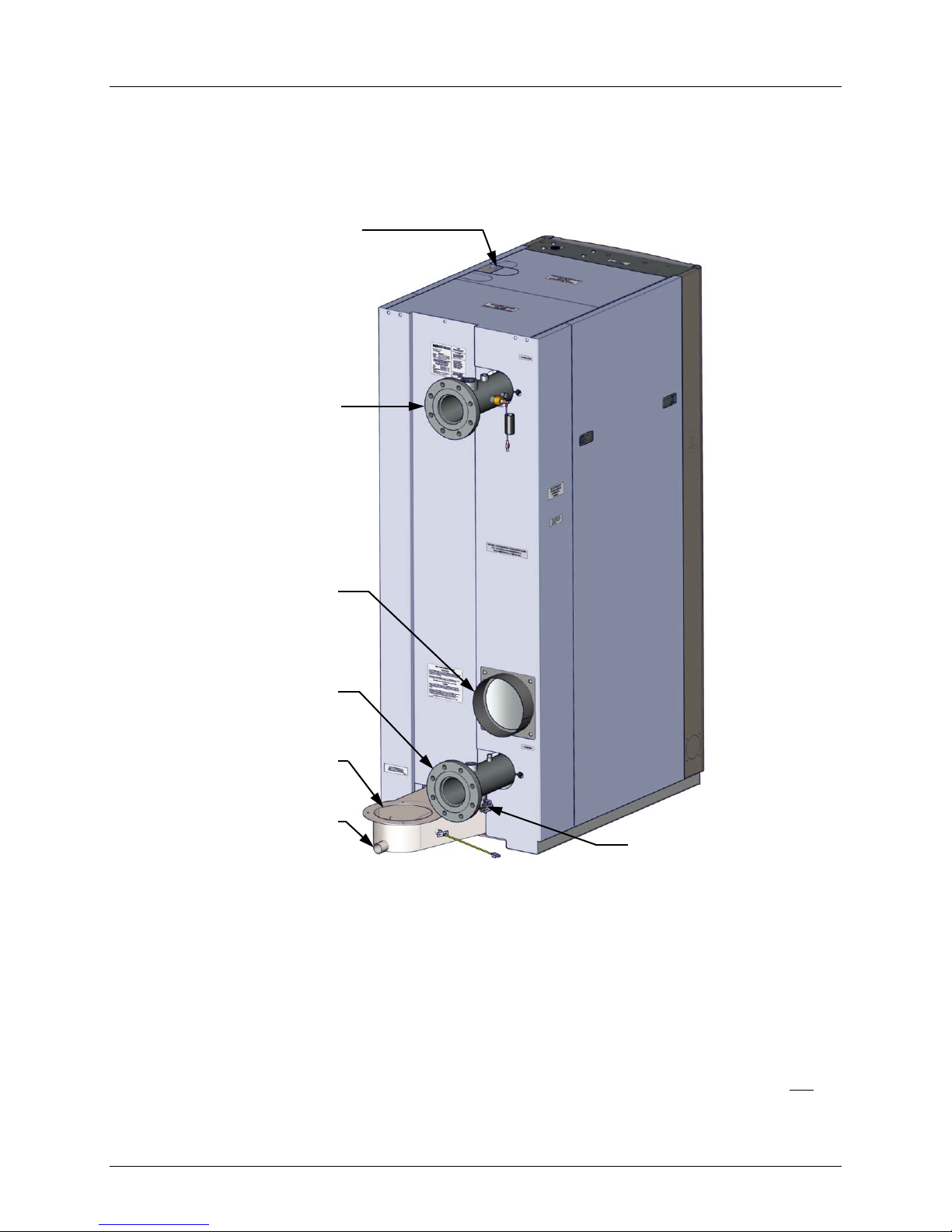
2.5 SUPPLY AND RETURN PIPING
The Benchmark Boiler utilizes 4” 150# flanges for the water system supply and return piping
connections. The physical location of the supply and return piping connections are on the rear of
the unit as shown in Figure 2-3.
2” GAS INLET
WATER OUTLET
AIR INLET
PRIMARY
WATER INLET
(RETURN)
DRAIN VALVE
Figure 2-3: Supply and Return Locations
2.6 PRESSURE RELIEF VALVE INSTALLATION
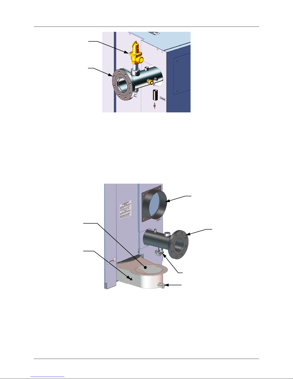
An ASME rated Pressure Relief Valve is supplied with each Benchmark Boiler. The pressure
rating for the relief valve must be specified on the sales order. Available pressure ratings range
from 30 psi to 160 psi. The relief valve is installed on the hot water outlet of the boiler as shown
in Figure 2-4. A suitable pipe joint compound should be used on the threaded connections. Any
excess should be wiped off to avoid getting any joint compound into the valve body. T he relief
valve must be piped to within 12 inches of the floor to prevent injury in the event of a discharge.
are allowed in the discharge line. In multiple unit installations t he discharge lines must not be
manifolded together. Each must be individually run to a suitable discharge location.
OMM-0097_0C AERCO International, Inc. • 100 Oritani Dr. • Blauvelt, NY 10913 Page 19 of 184
GF-142 Ph.: 800-526-0288
Page 20
Benchmark 1500 - 2000 Boilers
AIR INLET
PRIMARY
WATER INLET
1/4” AN AL Y Z E R
NPT PORT
EXHAST
MANIFOLD
CHAPTER 2 – INSTALLATION
PRESSURE
RELIEF VALVE
4” HOT BOILER
WATER OUTLET
Figure 2-4: P&T Relief Valve Location
2.7 CONDENSATE DRAIN & PIPING
The Benchmark Boiler is designed to condense water vapor from the flue products. Therefore,
the installation must have provisions for suitable condensate drainage or collection.
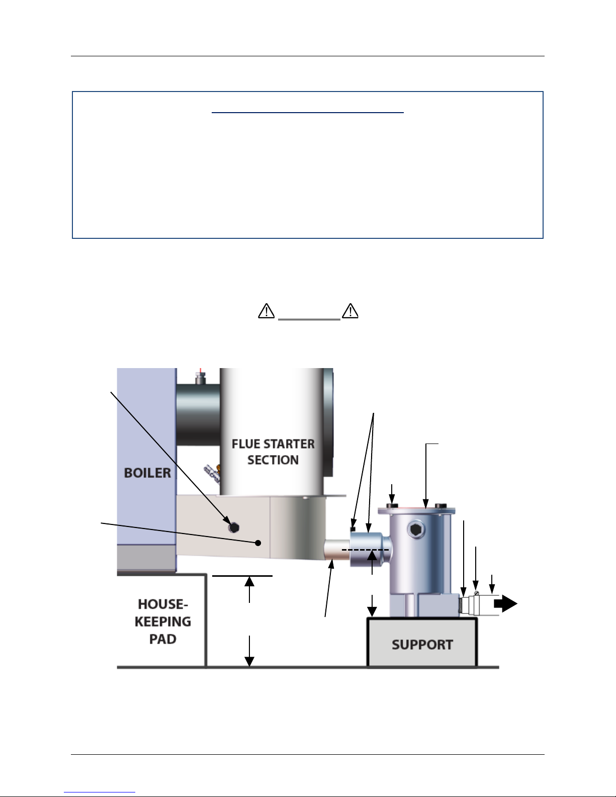
The condensate drain port located on the exhaust manifold (Figure 2-5) must be connected to
the condensate trap (P/N 24060) which is packed separately within the unit’s shipping container.
The condensate trap inlet features two integral O-rings and a thumbscrew to allow direct
connection of the drain port into the trap inlet. See the Condensate trap Installation instructions
and Figure 2-6 on the next page.
Figure 2-5: Condensate Drain Connection Location
A sample condensate trap installation is shown in Figure 2-6. The following general guidelines
must be observed to ensure proper condensate drainage:
• The condensate trap inlet (Figure 2-6) must be level the exhaust manifold drain port.
• The base of the condensate trap must be supported to ensure that it is level (horizontal).
• The trap must be removable for routine maintenance.
Page 20 of 184 AERCO International, Inc. • 100 Oritani Dr. • Blauvelt, NY 10913 OMM-0097_0C
Ph.: 800-526-0288 GF-142
DR AIN VALV E
CONDENSATE DRAIN PORT
Page 21
Benchmark 1500 - 2000 Boilers
CAUTION
COMBUTION
PROBE PORT
EXHAUST
MANIFOLD
3/4” NPT
NIPPLES
HOSE
CLAMP
DRAIN
TRAP INLET
TOP
(4 ea.)
1” DIAM.
HOSE
NOTE
ASSEMBLY.
4” MINIMUM
(6” MAXIMUM)
4”
CHAPTER 2 – INSTALLATION
While observing the above guidelines, install the condensate trap as follows:
Condensate Trap Installat ion
1. Connect the condensate trap inlet to the exhaust manifold drain connection by inserting
the drain port directly into the trap adaptor inlet, and t hen t ightening the inlet thumbscrew,
as shown in Figure 2-6. The inlet features two integral O-rings to prevent leakage.
2. At the condensate trap outlet, install a 3/4” NPT nipple.
3. Connect a length of 1” diameter polypropylene hose t o the trap outlet and secure with a
hose clamp.
4. Route the hose on the trap outlet to a nearby floor drain.
If a floor drain is not available, a condensate pump can be used to remove the c ondensate to
drain. The maximum condensate flow rate is 30 GPH. The condensate drain trap, associated
fittings and drain line must be removable for routine maintenance.
Use PVC, stainless steel, aluminum or polypropylene for condensate drain
piping (Figure 2-6). DO NOT use carbon or copper components.
ANALYZER
HOUSKEEPING
PAD MUST NOT
EXTEND
UNDER THE
CONDENSATE
EXHAUST
MANIFOLD
DRAIN PORT
INTEGRAL
ADAP TOR AND
THUMBSCREW
COVER
THUMB
SREWS
CONDENSATE
TRAP (P/N 24060)
T O
FLOOR
Figure 2-6: Sample Condensate Trap Installation (Right Side View)
OMM-0097_0C AERCO International, Inc. • 100 Oritani Dr. • Blauvelt, NY 10913 Page 21 of 184
GF-142 Ph.: 800-526-0288
Page 22

Benchmark 1500 - 2000 Boilers
CAUTION
CHAPTER 2 – INSTALLATION
2.8 GAS SUPPLY PIPING
The AERCO Benchmark Gas Components and Supply Design Guide, GF-2030 must be
consulted prior to designing or installing any gas supply piping.
WARNING
NEVER USE MATCHES, CANDLES, FLAMES OR OTHER
SOURCES OF IGNITION TO CHECK FOR GAS LEAKS
.
Many of the soaps used for gas pipe leak testing are corrosive to
metals. Therefore, piping must be rinsed thoroughly with clean
water after l eak checks have been completed.
NOTE
All gas piping must be arranged so that it does not interfere with
removal of any covers, inhibit service/maintenance, or restrict
access between the unit and walls, or another unit.
Benchmark 1500 MBH and 2000 MBH units contain a 2 inch NPT gas inlet connection on the
top of the unit, as shown in Figure 2-2 and 2-3.
Prior to installation, all pipes should be de-burred and internally cleared of any scale, metal
chips or other foreign particles. Do Not install any flexible connectors or unapproved gas
fittings. Piping must be supported from the floor, ceiling or walls only and must not be supported
by the unit.
A suitable piping compound, approved for use with natural gas, should be used. Any excess
must be wiped off to prevent clogging of components.
To avoid unit damage when pressure testing gas piping, the unit must be isolated fr om the gas
supply piping. At no time should the gas pressure applied to the unit exceed 14” W.C. A
thorough leak test of all external piping mus t be performed using a soap and water solution or
suitable equivalent. The gas piping used must meet all applicable codes.
2.8.1 Gas Supply Specifications.
The gas supply input specifications to the unit for Natural Gas are as follows:
• The maximum static pressure to the unit must not exceed 14” W.C.
• The gas supply pressure to the unit must be of sufficient capacity to provide 2000 cfh while
maintaining the gas pressure at 6 inches W.C. for FM gas trains operating at maximum
capacity.
2.8.2 Manual Gas Shutoff Valve
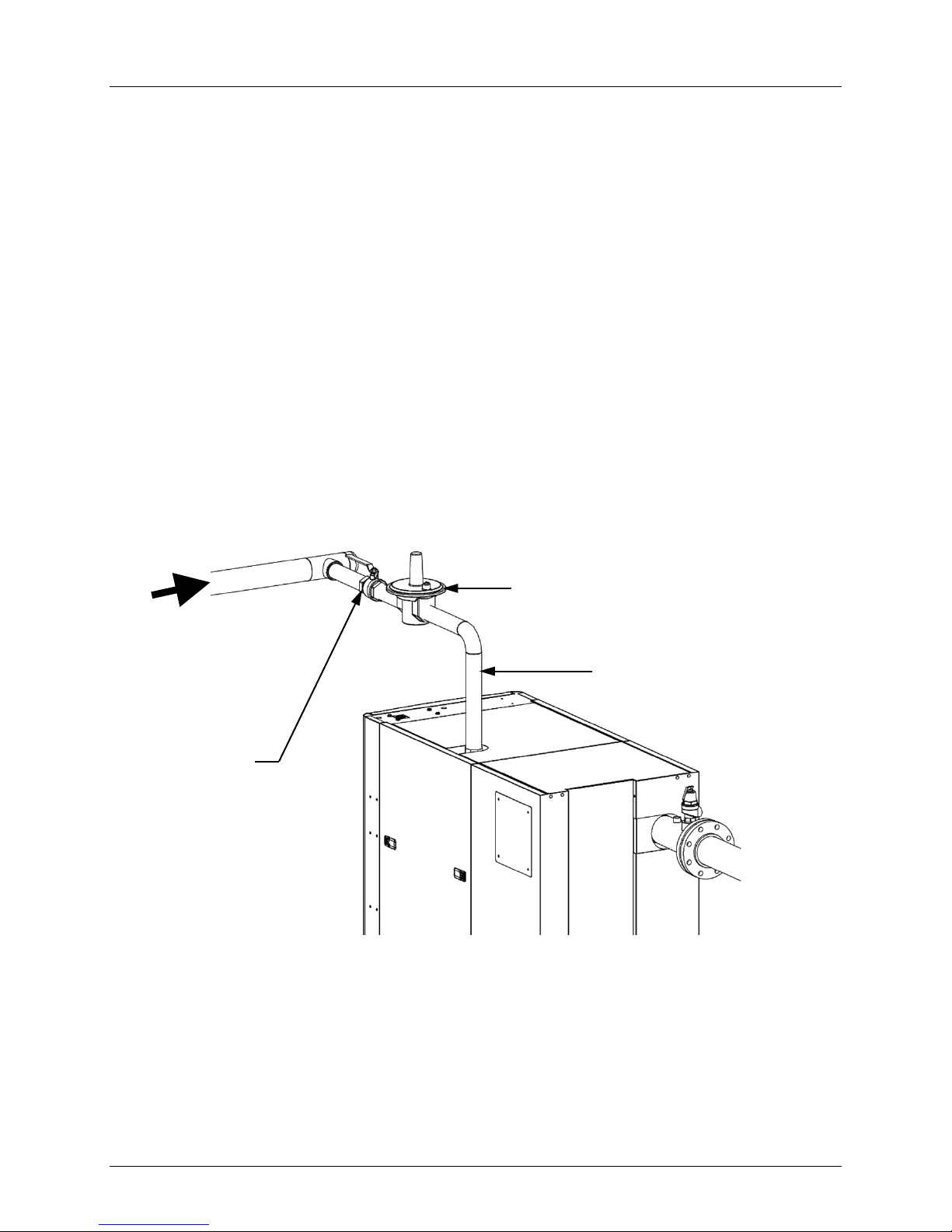
A manual shut-off valve must be installed in the gas supply line upstream of the boiler as shown
in Figure 2-7. Maximum allowable gas pressure to the boiler is 14” W.C.
Page 22 of 184 AERCO International, Inc. • 100 Oritani Dr. • Blauvelt, NY 10913 OMM-0097_0C
Ph.: 800-526-0288 GF-142
Page 23
Benchmark 1500 - 2000 Boilers
NATURAL GAS INLET
CHAPTER 2 – INSTALLATION
2.8.3 External Gas Supply Regulator
An external gas pressure regulator is required on the gas inlet piping under most conditions
(see sections 2.8.3.1 and 2.8.3.2, below). Regulators must conform to the following
specifications:
• The external natural gas regulat or must be capable of regulating 200,000 – 3,180,000
BTU/HR of natural g as while maintaining a gas pressure of 8.0” W.C. minimum t o the
unit.
• A lock-up style regulator MUST be used when gas supply pressure will exceed 14” W.C.
2.8.3.1
Massachusetts Installations Only
For Massachusetts installations, a mandatory external gas supply regulator must be positioned
as shown in Figure 2-7. The gas supply regulator must be properly vented to outdoors. Consult
the local gas utility for detailed requirements concerning venting of the supply gas regulator.
2.8.3.2
All Installations (Except Massachusetts)
For all installations (other than Massachusetts) that EXCEED 7” W.C. gas pressure, a
mandatory external gas supply regulator must be positioned as shown in Figure 2-7. No
regulator is required for gas pressures below 7” W.C. of pressure. Consult the local g as utility
for detailed requirements concerning venting of the supply gas regulator.
GAS PRESSURE REGULATOR
NATURAL
GAS SUPPLY
2” MANUAL
SHUT-OFF
VALVE
Figure 2-7: Manual Gas Shut-Off Valve Location
It is the responsibility of the customer to source and purchase the
appropriate gas regulator as described above. However, AERCO
offers for sale an appropriate regulator, which may be ordered at
the time of unit purchase or separately. Contact AERCO for more
information.
OMM-0097_0C AERCO International, Inc. • 100 Oritani Dr. • Blauvelt, NY 10913 Page 23 of 184
GF-142 Ph.: 800-526-0288
NOTE
Page 24
Benchmark 1500 - 2000 Boilers
WARNING
FUSE BLOCKS (2)
CHAPTER 2 – INSTALLATION
2.9 AC ELECTRICAL POWER WIRING
The AERCO Benchmark Electrical Power Wiring Guide, GF-2060, must be consulted prior to
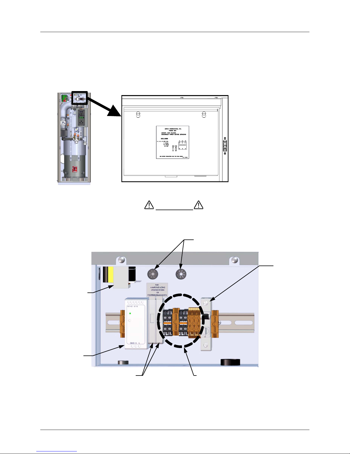
connecting any AC power wiring to the unit. External AC power connections are made to the
unit inside the Power Box on the front of the unit. Remove the front panel to access the Power
Box, which is mounted in the upper right corner of the unit as shown in Figure 2-8. Loosen the
two upper screws of the Power Box cover and remove cover to access the internal connections
shown in Figure 2-9.
THE POWER BREAKER SHOWN IN FIGURE 2-9 DOES NOT
REMOVE POWER FROM THE TERMINAL BLOCKS.
TRANSFORMER
Figure 2-8: Power Box Location with Cover Closed
WIRE CONDUITS
POWER
BREAKER
12V POWER
SUPPLY
Figure 2-9: Power Box Internal Components
With the exception of the transformer shown in Figure 2-9, all of t he components in the Power
Box are mounted on a DIN rail.
Page 24 of 184 AERCO International, Inc. • 100 Oritani Dr. • Blauvelt, NY 10913 OMM-0097_0C
Ph.: 800-526-0288 GF-142
TERMINAL BLOCKS
Page 25

Benchmark 1500 - 2000 Boilers
CHAPTER 2 – INSTALLATION
NOTE
All electrical conduit and hardware must be installed so that it
does not interfere with the removal of any unit covers, inhibit
service/maintenance, or prevent access between the unit and
walls or another unit.
2.9.1 Electrical Power Requirements
The Benchmark 1500 and Benchmark 2000 models are available in one voltage configuration:
• 120 VAC, Single-Phase, 60 Hz @ 20 Amps
The Power Box contains terminal blocks as shown in Figure 2-9. In addition, a label showing the
required AC power connections is provided on the front cover of the Power Box as shown in
Figure 2-10.
Figure 2-10: Power Box Cover Labels – 120VAC
Each unit must be connected to a dedicated electrical circuit. NO OTHER DEVICES SHOULD
BE ON THE SAME ELECTRICAL CIRCUIT AS THE BOILER.
A three-pole switch must be installed on the electrical supply line in an easily accessible location
to quickly and safely disconnect electrical service. DO NOT attach the switch to sheet metal
enclosures of the unit.
After placing the unit in service, the ignition safety shutoff device must be tested. If an external
electrical power source is used, the installed boiler must be electrically bonded to ground in
accordance with the requirements of the authority having jurisdiction. In the absence of such
requirements, the installation shall conform to National Electrical Code (NEC), ANSI/ NFPA 70
and/or the Canadian Electrical Code (CEC) Part I, CSA C22.1 Electrical Code.
For electrical power wiring diagrams, see the AERCO Benchmark Electrical Power Guide, (GF-
2060).
OMM-0097_0C AERCO International, Inc. • 100 Oritani Dr. • Blauvelt, NY 10913 Page 25 of 184
GF-142 Ph.: 800-526-0288
Page 26
Benchmark 1500 - 2000 Boilers
CAUTION
BOARD
CHAPTER 2 – INSTALLATION
2.10 FIELD CONTROL WIRING
Each unit is fully wired from the factory with an internal operating control system. No field control
wiring is required for normal operation. However, the C-More Control system used with all
Benchmark units does allow for some additional control and monitoring features. Wiring
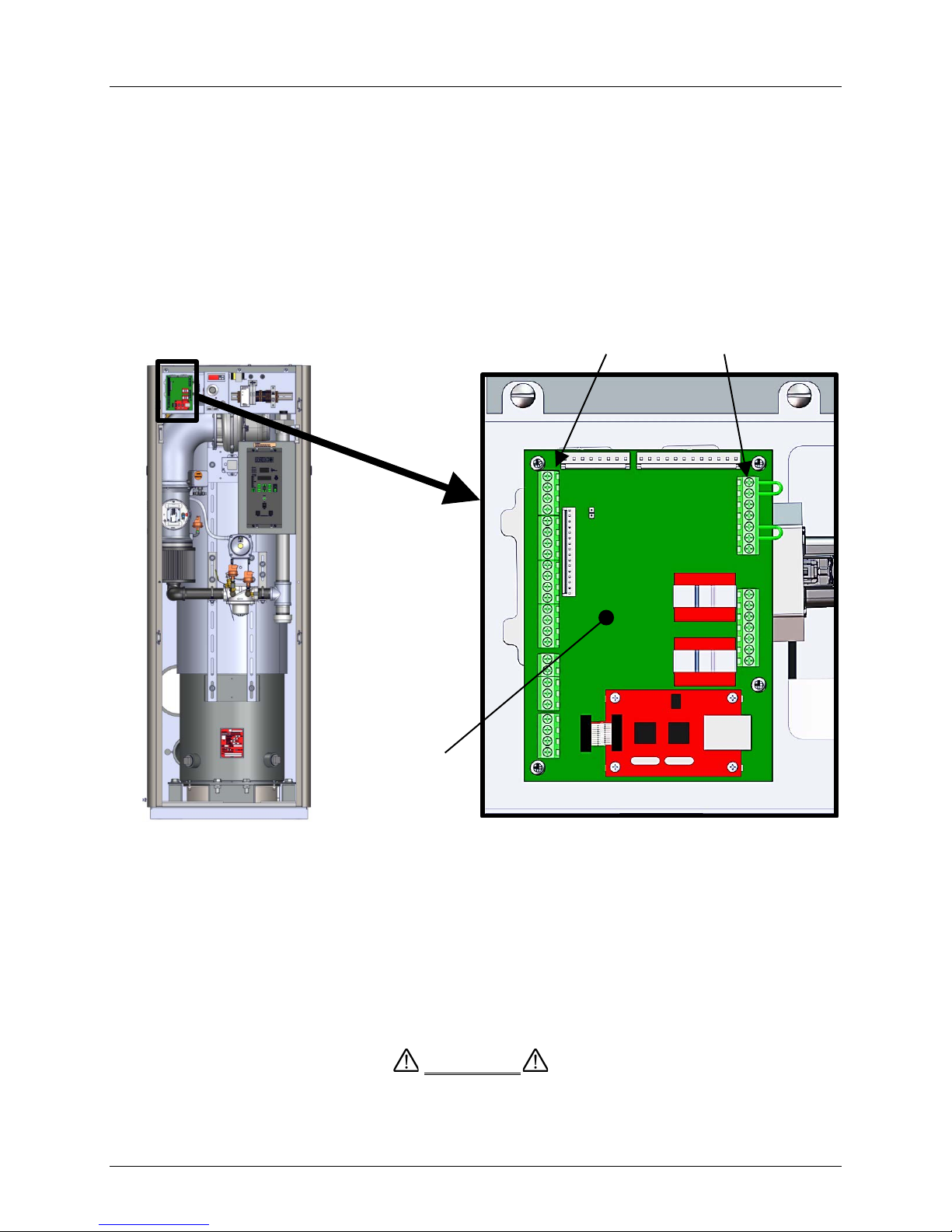
connections for these features are made on the Input/Output (I/O) board located behind the
removable front panel assembly of the unit. The I/O board is located in the upper-left portion on
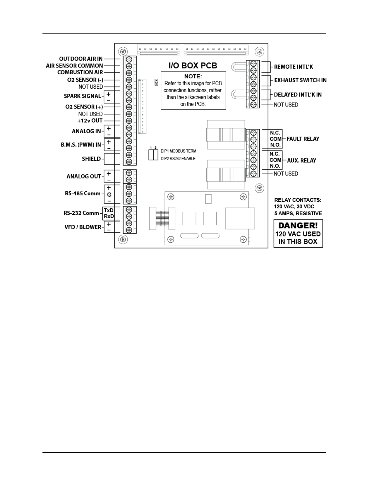
the front of the unit as shown in Figure 2-11. The I/O board terminal strip connections are shown
in Figure 2-12. All field wiring is installed from the rear of the panel by routing the wires through
one of the four bushings provided on the sides of the I/O board.
Refer to the wiring diagram provided below the I/O Box (Figure 2-12) when making all wiring
connections.
TERMINAL STRIPS
Figure 2-11: Input/Output (I/O) Box Location
Use Figure 2-12 to determine the functions of the I/O PCB
connections. Do not use the silkscreened labels on the PCB itself,
as these may not match the function names.
There is a diagram of the connection functions on the cover of the
I/O Box as well.
DO NOT make any connections to the I/O Box terminals labeled
“NOT USED”. Attempting to do so may cause equipment damage.
Page 26 of 184 AERCO International, Inc. • 100 Oritani Dr. • Blauvelt, NY 10913 OMM-0097_0C
Ph.: 800-526-0288 GF-142
I/O PCB
NOTE
Page 27
Benchmark 1500 - 2000 Boilers
CHAPTER 2 – INSTALLATION
Figure 2-12: I/O Box Terminal Strips
2.10.1 Outdoor Air In (OUT) & Air Sensor Common (COM)
The OUTDOOR AIR IN terminal is used for connecting an outdoor temperature sensor (AERCO
P/N GM-123525) as required primarily for the Indoor/Outdoor reset mode of operation. It can
also be used with another mode if it is desired to use the outdoor sensor enable/disable feature.
This feature allows the boiler to be enabled or disabled based on the outdoor air temperature.
The factory default for the outdoor sensor is DISABLED. To enable the sensor and/ or select an
enable/disable outdoor temperature, see the Configuration Menu in Chapter 3.
The outdoor sensor may be wired up to 200 feet from the boiler. It is connected to the
OUTDOOR AIR IN and AIR SENSO R COMMON terminals of the I/O PCB (Figure 2-12). Wire
the sensor using a twisted shielded pair wire from 18 to 22 AWG. There is no polarity to
observe when terminating these wires. The shield is to be connected only to the terminals
labeled SHIELD in the I/O Box PCB. The sensor end of the shield must be left free and
ungrounded.
When mounting the sensor, it must be located on the North side of the building where an
average outside air temperature is expected. The sensor must be shielded from direct sunlight
as well as impingement by the elements. If a shield is used, it must allow for free air circulation.
OMM-0097_0C AERCO International, Inc. • 100 Oritani Dr. • Blauvelt, NY 10913 Page 27 of 184
GF-142 Ph.: 800-526-0288
Page 28

Benchmark 1500 - 2000 Boilers
CHAPTER 2 – INSTALLATION
2.10.2 COMBUSTION AIR Terminal
The COMBUSTIAN AIR term in al is used to monitor the combustion air temperature sensor. This
input is always enabled and is a “to view only” input that can be seen in the operating menu.
The sensor is an AERCO BALCO wire sensor P/N 12449. A resistance chart for this sensor is
provided in APPENDIX C. This sensor is an active part of the combustion control system and
must be operational for accurate air/fuel mixing control.
2.10.3 O2 SENSOR (O2+ & O2-)
The O2 SENSOR (+) and O2 SENSOR (–) terminals are used to connect an integrated oxygen
sensor to the I/O Box PCB. The O
More Control system after a 60 second warm-up period.
2.10.4 SPAR K SIGNAL (FLW+ & FLW-)
The two SPARK SIGNAL terminals permit an external current sensor to be connected for
ignition spark monitoring purposes. If no spark is present during the ignition sequence, the
controller will shut down and display a fault message.
2.10.5 Analog In (+ & -)
The two ANALOG IN terminals are used when an external signal is used to change the setpoint
(Remote Setpoint Mode) of the boiler.
concentration is displayed in the operating menu of the C -
2
Either a 4 to 20 mA /1 to 5 VDC or a 0 to 20 mA/ 0 to 5 VDC signal may be used to vary the setpoint or air/fuel valve position. The factory default setting is for 4 to 20 mA / 1 to 5 VDC,
however this may be changed to 0 to 20 mA / 0 to 5 VDC using the Configuration Menu
described in Chapter 3.
If voltage rather than current is selected as the drive signal, a DIP switch must be set on the
PMC Board located inside the C-More Control Box. Contact the AERCO factory for information
on setting DIP switches.
All supplied signals must be floating (ungrounded) signals. Connections between the source
and the boiler’s I/O PCB (Figure 2-12) m ust be made using twisted shielded pair of 18–22 AWG
wire such as Belden 9841. Polarity must be maintained and the shield must be connected only
at the source end and must be left floating (not connected) at the Boiler’s I/O PCB.
Whether using voltage or current for the drive signal, they are linearly mapped to a 40°F to
240°F setpoint or a 0% to 100% air/fuel valve position. No scaling for these signals is provided
2.10.6 B.M.S. (PWM) In (BMS+ & BMS-)
These terminals are only used to connect to legacy AERCO Boiler Management Systems
(BMS), which utilize a 12 millisecond, ON/OFF duty cycle and is Pulse W idth Modulated (PWM)
to control valve position. A 0% valve position = a 5% ON pulse and a 100% valve position = a
95% ON pulse. Note that thes e connections cannot be used with the AERCO Control System
(ACS).
2.10.7 Shield (SHLD & SHLD)
The SHIELD terminals are used to terminate any shields used on sensor wires connected to the
unit. Shields must only be connected to these terminals.
2.10.8 Analog Output (+ & -)
The ANALOG OUT terminals (+ & -) output from 0 to 20 mA and may be used to monitor
Setpoint, Outlet Temperature, Valve Pos ition 4-20 mA, Valve Position 0-10v or be set to OFF.
Default sett ing in th e C-More controller is Valve Position 0-10v and settings behave as follows:
Page 28 of 184 AERCO International, Inc. • 100 Oritani Dr. • Blauvelt, NY 10913 OMM-0097_0C
Ph.: 800-526-0288 GF-142
Page 29

Benchmark 1500 - 2000 Boilers
CHAPTER 2 – INSTALLATION
• When 0-10VDC is selected, t he voltage output is used by the controller to modulate t he
combustion blower via the I/O Box terminals labeled VFD/Blower (Section 2.10.11).
• If “On Board” boiler or Water Heater Management is enabled, the Analog Output
terminals are used to drive the isolation valve, open and closed.
• When the 4-20mA is selected for the Analog Output, the 0-10VDC is disabled at the
VFD/Blower terminals, and the selected output is available at the terminals labeled
Analog Output +/-.
2.10.9 RS-485 Comm (+, GND, & -)
The RS-485 communication terminals are used when the boiler plant is being controlled by an
Energy Management System (EMS) or an AERCO Control System (ACS) using Modbus (RS-
485) communication.
2.10.10 RS-232 Comm (TxD & RxD)
The RS-232 communication terminals permit a laptop c omputer or other suitable terminal to be
connected to the boiler. The RS-232 communication feature permits viewing or changing of
Control Panel menu options and also provides access to data logs showing fault and sensor log
displays.
2.10.11 VFD/Blower (0-10 & AGND)
These terminals (0-10 & AGND) send an analog signal to control the blower speed. When any
of the 4-20mA opt ions is selected for the Analog Outputs (Section 2.10.8), the output from the
VFD/Blower terminals is disabled.
2.10.12 Interlocks
The unit offers two interlock circuits for interfacing with Energy Management Systems and
auxiliary equipment such as pumps or louvers or other accessories. These interlocks are called
the Remote Interlock and Delayed Interlock (Figure 2-12). Bo th in terlocks, described below, are
factory wired in the closed position (using jumpers).
NOTE
Both the Delayed Interlock and Remote Interlock must be in the
closed position for the unit to fire.
2.10.12.1
The remote interlock circuit is provided to remotely start (enable) and st op (disable) the unit
if desired. The circuit is 24 VAC and comes factory pre-wired closed (jumped).
2.10.12.2
The delayed interlock is typically used in conjunction with the AUXILIARY RELAY
CONTACTS described in section 2.10.14. This interlock circuit is located in the purge
section of the start string. It can be connected to the proving device (end switch, flow
switch etc.) of an auxiliary piece of equipment started by the unit’s auxiliary relay. The
delayed interlock must be closed for the boiler to fire. If the delayed interlock is connected
to a proving device that requires time to close (make), a time delay (AUX START ON DLY)
that holds the start sequence of the unit long enough for a proving switch to make (close)
can be programmed.
Remote Interlock In (OUT & IN)
Delayed Interlock In (OUT & IN)
Should the proving switch not prove within the programmed time frame, the unit will shut
down. The AUX START ON DLY can be programmed from 0 to 120 seconds. This option
is located in the Configuration Menu (Chapter 3).
OMM-0097_0C AERCO International, Inc. • 100 Oritani Dr. • Blauvelt, NY 10913 Page 29 of 184
GF-142 Ph.: 800-526-0288
Page 30

Benchmark 1500 - 2000 Boilers
Selkirk Corporation - Heatfab Division
Watertown Supply
M. A. Peacard
www.mapeacard.com
Glover Sheet Meatal, Inc.
www.gloversheetmetal.com
CHAPTER 2 – INSTALLATION
2.10.13 Fault Relay (NC, COM, & NO)
The fault relay is a single pole double throw (SPDT) relay having a normally open and normally
closed set of relay contacts that are rated for 5 amps at 120 VAC and 5 amps at 30 VDC. The
relay energizes when any fault condition occurs and remains energized until the fault is cleared
and the CLEAR button is depressed. The fault relay connections are shown in Figure 2-12.
2.10.14 Auxiliary Relay Contacts (NC, COM, & NO)
Each unit is equipped with a single pole double throw (SPDT) relay that is energized when there
is a demand for heat and de-energized after the demand for heat is satisfied. The relay is
provided for the control of auxiliary equipment, such as pumps and louvers, or can be used as a
unit status indictor (firing or not firing). Its cont acts are rated for 120 VAC @ 5 amps. Refer to
Figure 2-12 to locate th e AUXILLIARY RELAY terminals for wiring connections.
2.11 FLUE GAS VENT INSTALLATION
AERCO Gas Fired Venting and Combustion Air Guide, GF-2050 must be consulted before any
flue or combustion air venting is designed or installed. Suitable, U/L approved, positive
pressure, watertight vent materials MUST be used for safety and UL certification. Because the
unit is capable of discharging low temperature exhaust gases, the flue must be pitched back
towards the unit a minimum of 1/4" per foot to avoid any condensate pooling and to allo w for
proper drainage.
While there is a positive flue pressure during operation, the combined pressure drop of vent and
combustion air systems must not exceed 140 equivalent feet or 0.8” W.C. Fittings as well as
pipe lengths must be calculated as part of the equivalent length. For a natural draft installation
the draft must not exceed - 0.25” W.C. These factors must be planned into the vent installation.
If the maximum allowable equivalent lengths of piping are exceeded, the unit will not operate
properly or reliably.
For Massachusetts installations, the following companies provide vent systems which conform
to all applicable requirements for installations within the Commonwealth of Massachusetts.
Contact information is as follows:
130 Industrial Blvd.
Turners Falls, MA 01376
Phone: 1-800-772-0739
www.heat-fab.com
1250 Massachusetts Ave.
Boston MA 02125-1689
Phone: (617) 288-0629
33Grove St.
Watertown, MA 02472
Phone: (617) 924-2840
http://www.watertownsupply.com/
44 Riverdale Ave.
Newton, MA 02485
Phone: (617) 527-8178
2.12 COMBUSTION AIR
The AERCO Benchmark Boiler Venting and Combustion Air Guide, GF-2050 MUST be
consulted before any flue or inlet air venting is designed or installed. Air supply is a direct
requirement of ANSI 223.1, NFPA-54, CSA B149.1 and local codes. These codes should be
consulted before a permanent design is determined.
The combustion air must be free of chlorine, halogenated hydrocarbons or other chemicals that
can become hazardous when used in gas-fired equipment. Common sources of these
compounds are swimming pools, degreasing compounds, plastic processing, and refrigerants.
Page 30 of 184 AERCO International, Inc. • 100 Oritani Dr. • Blauvelt, NY 10913 OMM-0097_0C
Ph.: 800-526-0288 GF-142
Page 31

Benchmark 1500 - 2000 Boilers
CHAPTER 2 – INSTALLATION
Whenever the environment contains these types of chemicals, combustion air MUST be
supplied from a clean area outdoors for the protection and longevity of the equipment and
warranty validation.
The more common methods of combustion air supply are outlined in the following sections. For
combustion air supply from ducting, consult the AERCO GF-2050, Gas Fired Venting and
Combustion Air Guide.
2.12.1 Combustion From Outside the Building
Air supplied from outside the building must be provided through two permanent openings. For
each unit these two openings must have a free area of not less than one square inch for each
4000 BTUs input of the equipment or 375 square inches of free area for the BMK 1500 or 500
square inches of free area for t he BMK 2000. The free area must take into account restrict ions
such as louvers and bird screens. For Canada installations, refer to the requirements spec ified
in CSA B149.1-10, sections 8.4.1 and 8.4.3.
2.12.2 Combustion Air from Inside the Building
When combustion air is provided from within the building, it must be supplied through two
permanent openings in an interior wall. Each opening must have a free area of not less than
one square inch per 1000 BTUH of total input or 3000 square inches of free area. The free area
must take into account any restrictions, such as louvers.
2.13 DUCTED COMBUSTION AIR
For ducted combustion air installations, the air ductwork must then be attached directly to the air
inlet connection on the sheet metal enclosure.
In a ducted combustion air application, the combustion air ducting pressure losses must be
taken into account when calculating the total maximum allowable venting run. See the AERCO
Benchmark Venting and Combustion Air Guide, GF-2050. When using the unit in a ducted
combustion air configuration, each unit must have a minimum 8 inch diameter connection at the
unit.
OMM-0097_0C AERCO International, Inc. • 100 Oritani Dr. • Blauvelt, NY 10913 Page 31 of 184
GF-142 Ph.: 800-526-0288
Page 32

Benchmark 1500 - 2000 Boilers
CHAPTER 2 – INSTALLATION
(This page intentionally blank)
Page 32 of 184 AERCO International, Inc. • 100 Oritani Dr. • Blauvelt, NY 10913 OMM-0097_0C
Ph.: 800-526-0288 GF-142
Page 33

Benchmark 1500 - 2000 Boilers
WARNING
CAUTION
CHAPTER 3 – OPERATION
CHAPTER 3. OPERATION
3.1 INTRODUCTION
The information in this Chapter provides a guide to the operation of the Benchmark Boiler using
the Control Panel mounted on the front of the unit. It is imperative that the initial startup of this
unit be performed by factory trained personnel. Operation prior to initial startup by factory
trained personnel may void the equipment warranty. In addition, the following WARNINGS and
CAUTIONS must be observed at all times.
WARNING
ELECTRICAL VOLTAGES IN THIS SYSTEM INCLUDE 120 AND
24 VOLTS AC. IT MUST BE SERVICED ONLY BY FACTORY
CERTIFIED SERVICE TECHNICIANS.
DO NOT ATTEMPT TO DRY FIRE THE UNIT. STA RTING T HE
UNIT WITHOUT A FULL WATER LEVEL CAN SERIOUSLY
DAMAGE THE UNIT AND MAY RESULT IN INJURY TO
PERSONNEL OR PROPERT Y DAMAGE. THIS SITUATION WILL
VOID ANY WARRANTY.
All of the installation procedures in Chapter 2 must be completed
before attempting to start the unit.
3.2 CONTROL PANEL DESCRIPTION
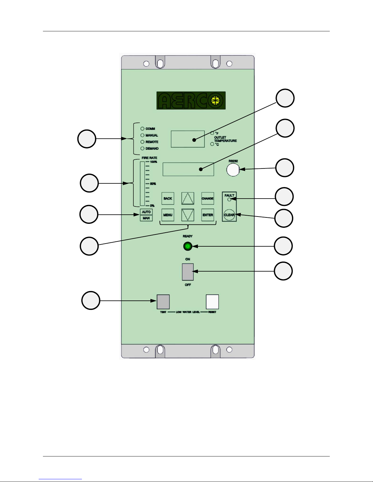
All Benchmark boilers utilize the C-More Control Panel shown in Figure 3-1. This panel contains
all of the controls, indicators and displays necessary to operate, adjust and troubleshoot the
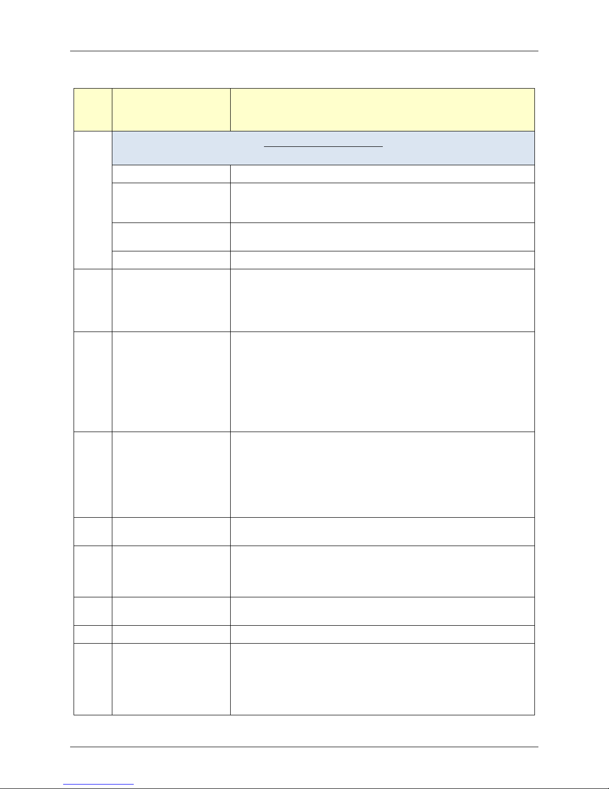
boiler. These operating controls, indicators and displays are listed and described in Table 3-1.
Additional information on these items is provided in the individual operating procedures and
menu descriptions provided in this Chapter.
OMM-0097_0C AERCO International, Inc. • 100 Oritani Dr. • Blauvelt, NY 10913 Page 33 of 184
GF-142 Ph.: 800-526-0288
Page 34
Benchmark 1500 - 2000 Boilers
3
1 8 9
10
11 7 6 5 *4
12
2
CHAPTER 3 – OPERATION
Figure 3-1: Control Panel Front View
If there is a requirement to use the RS232 port (Item 4) on the CMore controller front panel, contact AERCO to purchase the
RS232 Adaptor Cable (P/N 124675), which is designed for this
purpose. This cable features a DB9 connector for connection to
older computers with serial ports or can be used with a Serial-toUSB adaptor for use in modern computer USB ports.
Page 34 of 184 AERCO International, Inc. • 100 Oritani Dr. • Blauvelt, NY 10913 OMM-0097_0C
Ph.: 800-526-0288 GF-142
*NOTE
Page 35
Benchmark 1500 - 2000 Boilers
CONTROL,
DISPLAY
indicate whether the displayed temperature is in degrees
Vacuum Fluorescent Display (VFD) consists of 2 lines each
Port permits a Laptop Computer or External Modem to be
CHAPTER 3 – OPERATION
Table 3-1: Operating Controls, Indicators and Displays
ITEM
NO.
1
2
3
INDICATOR OR
Four Status LEDs indicate the current operating status as follows:
COMM
MANUAL
REMOTE
DEMAND
OUTLET
TEMPERATURE
Display
VFD Display
FUNCTION
LED Status Indicators
Lights when RS-232 communication is occurring
Lights when the valve position (fire rate) is bei ng controlled using
the front panel keypad. This mode of operation is for service
technician use only.
Lights when the un it is being con trolled b y an external sig nal from
an Energy Management System
Lights when there is a demand for heat.
3–Digit, 7–Segm ent LED display continuously displays the outlet
water temperature. The °F or °C LED nex t to the display lights to
Fahrenheit or degrees Celsius. The °F or °C blinks when operating
in the Deadband Mode.
capable of displaying up to 16 alphanumeric characters. The
information displayed includes:
• Startup Messages
• Fault Messages
• Operating Status Messages
• Menu Selection
connected to the unit’s Con trol Pane l. AERCO of fer s for purchas e
the RS232 Adaptor Cable (P/N 124675), which is designed to
RS-232 Port
4
FAULT Indicator
5
CLEAR Key
6
READY Indicator
7
ON/OFF Switch
8
LOW WATER LEVEL
9
TEST/RESET Switches
work with this port. This cable features a DB9 connector for
connection to older computers with serial ports or can be used
with a Serial-to-USB adaptor for use in modern computer USB
ports.
Red FAULT LED indicator lights when a boiler alarm condition
occurs. An alarm message will appear in the VFD.
Turns off the FAULT in dica tor an d c l ears t he al ar m message if the
alarm is no longer valid. Lock out type alarms will be latched and
cannot be cleared by simply pressing this key. Troubleshooting
may be required to clear these types of alarms.
Lights ON/OFF switch is set to ON and all Pre-Purge conditions
have been satisfied.
Enables and disables boiler operation.
Allows operator to test operation of the water level monitor.
Pressing TEST opens the water level prob e c irc uit an d s imulates a
Low Water Level alarm.
Pressing RESET resets the water level monitor circuit.
Pressing the CLEAR key (item 6) resets the display.
OMM-0097_0C AERCO International, Inc. • 100 Oritani Dr. • Blauvelt, NY 10913 Page 35 of 184
GF-142 Ph.: 800-526-0288
Page 36

Benchmark 1500 - 2000 Boilers
DISPLAY
2. The Menu categories wrap around in the order
will bring you back to the default status display in the
pressing this key will select the displayed menu category.
key was pressed and the menu item is
key will decrement the
Permits a setting to be changed (edited). When the
key is pressed, the displayed menu item will
modified menu settings in memory. The
mode, the front panel controls are enabled and the
status LED lights. Manual operation is for
status LED will be off and the front panel controls
continuously shows the
CHAPTER 3 – OPERATION
Table 3-1: Operating Controls, Indicators and Displays – Continued
ITEM
NO.
10
CONTROL,
INDICATOR OR
FUNCTION
MENU Keypad
Six (6) keys which provide the following functions for the Control Panel Menus:
Steps through the main menu categories shown in Figure
MENU
3shown.
Allows you to go back to the previous menu level without
changing any information. Continuously pressing this key
BACK
VFD. Also, this key allows you to go back to the top of a
main menu category.
When in one of the main menu categories (Figure 3-2),
pressing the ▲ arrow key will select the displayed m enu
▲ (UP) Arrow
category. If the CHANGE key was pressed and the menu
item is flashing, pressing the ▲ arrow key will increment
the selected setting.
When in one of the main menu categories (Figure 3-2),
▼ (DOWN) Arrow
If the CHANGE
flashing, pressing the ▼ arrow
selected setting.
CHANGE
CHANGE
begin to flash. Pressing the ▲ or ▼ arrow key when the
item is flashing will increment or decrement the displayed
setting.
ENTER
Saves the
display will stop flashing.
This switch toggles the boiler between the Automatic and
Manual modes of operation. When in the Manual (MAN)
MANUAL
11
AUTO/MAN Switch
service only.
When in the Automatic (AUTO) mode, the MANUAL
disabled.
20 segment red LED bargraph
12
Page 36 of 184 AERCO International, Inc. • 100 Oritani Dr. • Blauvelt, NY 10913 OMM-0097_0C
Ph.: 800-526-0288 GF-142
VALVE POSITION
Bargraph
Air/Fuel Valve position in 5% increments from 0 to 100%
Page 37

Benchmark 1500 - 2000 Boilers
CHAPTER 3 – OPERATION
3.3 CONTROL PANEL MENUS
The Control Panel incorporates an extensive menu structure which permits the operator to set
up, and configure the unit. The menu structure consists of five major menu categories which are
applicable to this manual. These categories are shown in Figure 3-2. Each of the menus
shown, contain options which permit operating parameters to be viewed or changed. The
menus are protected by a password levels to prevent unauthorized use.
Prior to entering the correct password, the options contained in the Operation, Setup,
Configuration and Tuning Menu categories can be viewed. However, with the exception of
Internal Setpoint Temperature (Configuration Menu), none of the viewable menu options can be
changed.
Once the valid level 1 password (159) is entered, the options list ed in the Setup. Configuration
and Tuning Menus can be viewed and changed, if desired. The Combustion Cal Menu is
protected by the level 2 password (6817) which is used in Chapter 4 to perform combustion
calibration prior to service use.
3.3.1 Menu Processing Procedure
Accessing and initiating each menu and option is accomplished using the Menu Keys shown in
Figure 3-1. Therefore, it is imper ative that you be thoroughly familiar with the following basic
steps before attempting to perform specific menu procedures:
Menu Processing Procedure
1. The Control Panel will normally be in the Operating Menu and the VFD will display the
current unit status. Pressing the ▲ or ▼ arrow key will display the other available data
items in the Operating Menu.
2. Press the MENU key. The display will show the Setup Menu, which is the next menu
category shown in Figure 3-2. This menu contains the Password option which must be
entered if other menu options will be changed.
3. Continue pressing the MENU key until the desired menu is displayed.
4. With the desired menu displayed, press the ▲ or ▼ arrow key. The first option in the
selected menu will be displayed.
5. Continue to press the ▲ or ▼ arrow key until the desired menu option is displayed.
Pressing the ▲ arrow key will display the available menu options in the Top-Down
sequence. Pressing the ▼ arrow key will display the options in the Bottom-Up sequence.
The menu options will wrap-around after the first or last available option is reached.
6. To change the value or setting of a displayed menu option, press the CHANGE key. The
displayed option will begin to flash. Press the ▲ or ▼ arrow key to scroll through the
available menu option choices for the option to be changed. The menu option choices do
not wrap around.
7. To select and store a changed menu item, press the ENTER key.
OMM-0097_0C AERCO International, Inc. • 100 Oritani Dr. • Blauvelt, NY 10913 Page 37 of 184
GF-142 Ph.: 800-526-0288
Page 38
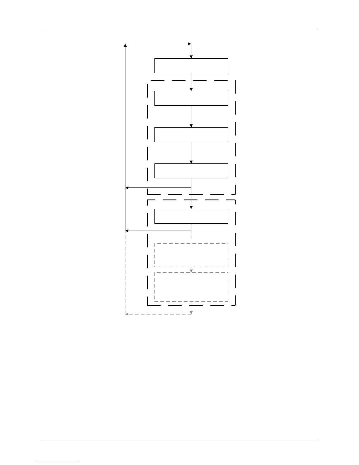
Benchmark 1500 - 2000 Boilers
OPERATING
SETUP
CONFIGURATION
TUNING
COMBUSTION CAL
CALIBRATION
(NOT USED IN THIS O & M)
SEE GF-112 FOR MENU ITEM
DESCRIPTIONS
LEVEL 2 PWD
LEVEL 1 PWD
DIAGNOSTICS
(NOT USED IN THIS O & M)
SEE GF-112 FOR MENU ITEM
DESCRIPTIONS
CHAPTER 3 – OPERATION
The following sections provide brief descriptions of the
options contained in each menu. Refer to Appendix A for
detailed descriptions of each menu option. Refer to
Page 38 of 184 AERCO International, Inc. • 100 Oritani Dr. • Blauvelt, NY 10913 OMM-0097_0C
Ph.: 800-526-0288 GF-142
Appendix B for listings and descriptions of displayed startup,
status and error messag es.
Figure 3-2: Menu Structure
NOTE
Page 39
Benchmark 1500 - 2000 Boilers
Available Choices or Limits
Minimum
Maximum
Status Message
Active Setpoint
40°F
240°F
Inlet Temp
40°F
140°F
Air Temp
-70°F
245°F
Outdoor Temp*
-70°F
130°F
Valve Position In
0%
100%
Valve Position Out*
0%
100%
Exhaust Temp
°F
°F
Flame Strength
0%
100%
Oxygen Level
0%
21%
Run Cycles
0
999,999,999
Run Hours
0
999,999,999
Fault Log
0
19
0
CHAPTER 3 – OPERATION
3.4 OPERATING MENU
The Operating Menu displays a number of key operating parameters for the unit as listed in
Table 3-2. This menu is “Read-Only” and does not allow personnel to change or adjust any
displayed items. Since this menu is “Read-Only”, it can be viewed at any time without entering a
password. Pressing the ▲ arrow key to display the menu items in the order listed (Top-Down).
Pressing the ▼ arrow key will display the menu items in reverse order (Bottom-Up).
Table 3-2: Operating Menu
Menu Item Display
Default
*NOTE
The Outdoor Temp and Valve Position Out display items shown
with an asterisk in Table 3-2 will not be displayed unless the
Outdoor Sensor function has been enabled in the Configuration
Menu (Table 3-4).
3.5 SETUP MENU
The Setup Menu (Table 3-3) permits the operator to enter the unit password (159) which is
required to change the menu options. To prevent unauthorized use, the password will time-out
after 1 hour. Therefore, the correct password must be reenter ed when required. In addition to
permitting password entries, the Setup Menu is also used to enter date and time, units of
temperature measurements and entries required for external communication and control of the
unit via the RS-232 port. A view-only software version display is also provided to indicate the
current Control Box software version.
OMM-0097_0C AERCO International, Inc. • 100 Oritani Dr. • Blauvelt, NY 10913 Page 39 of 184
GF-142 Ph.: 800-526-0288
Page 40
Benchmark 1500 - 2000 Boilers
Available Choices or Limits
Minimum
Maximum
Passsword
0
9999
0
Language
English
English
Time
12:00 am
11:59 pm
Unit of Temp
Fahrenheit or Celsius
Fahrenheit
Comm Address
0
127
0
Baud Rate
2400, 4800, 9600, 19.2K
9600
Upload Timer
0 0
Unit Alpha
A Z A
Unit Serial #
0000
9999
0000
C-More Year
0
99
11
C-More Serial #
0
9999
0000
C-More Alpha
A Z A
IP Address
Software
Ver 0.00
Ver 9.99
CHAPTER 3 – OPERATION
Table 3-3: Setup Menu
Menu Item Display
Default
Date 01/01/00 12/31/99
Unit Year 0 99 00
3.6 CONFIGURATION MENU
The Configuration Menu shown in Table 3-4 permits adjustment of the Internal Setpoint (Setpt)
temperature regardless of whether the valid password has been entered. Setpt is required for
operation in the Constant Setpoint mode. The remaining options in this menu require the valid
password to be entered, prior to changing existing entries. This menu contains a number of
other configuration settings which may or may not be displayed, depending on the current
operating mode setting.
NOTE
The Configuration Menu settings shown in Table 3-4 are FactorySet in accordance with the requirements specified for each
individual order. Therefore, under normal operating conditions, no
changes will be required.
Page 40 of 184 AERCO International, Inc. • 100 Oritani Dr. • Blauvelt, NY 10913 OMM-0097_0C
Ph.: 800-526-0288 GF-142
Page 41
Benchmark 1500 - 2000 Boilers
Available Choices or Limits
Minimum
Maximum
CHAPTER 3 – OPERATION
Table 3-4: Configuration Menu
Menu Item Display
Internal Setpt Lo Temp Limit Hi Temp Limit 130°F
KC Boiler, KC Boiler LN,
BMK Boiler Std, BMK Boiler LN,
BMK Blr Std Dual, BMK Blr LN, KC
Unit Type
Water Heater ,
KC Wtr Heater LN,
Innovation WH,
BMK Blr LN Dual
Unit Size
(Only the unit sizes
available for the Unit
Type will be displayed)
Fuel Type
750 MBH, 800 MBH 1000 MBH,
1500 MBH, 2000 MBH,
2500 MBH, 3000 MBH,
6000 MBH
Natural Gas or Propane Natural Gas
Constant Setpoint,
Remote Setpoint,
Boiler Mode
Direct Drive,
Combination,
Outdoor Reset
Default
BMK Boiler LN
1500 MBH
or
2000 MBH
Constant
Setpoint
Remote Signal
(If Mode = Remote
Setpoint, Direct Drive or
Combination)
Outdoor Sensor
PWM Input (Legacy BMS), Network
4 – 20 mA/1 – 5V
0 -20 mA/0 – 5V
4 – 20 mA,
1-5V
Enabled or Disabled Disabled
*Bldg Ref Temp
(If Mode = Outdoor
40°F 230°F 70°F
Reset)
*Reset Ratio
(If Mode = Outdoor
0.1 9.9 1.2
Reset)
*System Start Tmp
(If Outdoor Sensor =
30°F 100°F 60°F
Enabled)
Setpt Lo Limit 40°F Setpt Hi Limit 60°F
Setpt Hi Limit
Setpt Lo Limit 210°F 140°F
Temp Hi Limit 40°F 210°F 160°F
*NOTE
The Bldg Ref Temp and Reset Ratio Menu Items are only
displayed when the Outdoor Sensor is set to “Enabled”.
OMM-0097_0C AERCO International, Inc. • 100 Oritani Dr. • Blauvelt, NY 10913 Page 41 of 184
GF-142 Ph.: 800-526-0288
Page 42
Benchmark 1500 - 2000 Boilers
Available Choices or Limits
Minimum
Maximum
Available Choices or Limits
Minimum
Maximum
CAUTION
CHAPTER 3 – OPERATION
Table 3-4: Configuration Menu - Continued
Menu Item Display
Max Valve Position
Pump Delay Timer
Aux Start On Dly
40% 100% 100%
0 min. 30 min. 0 min.
0 sec. 120 sec. 0 sec.
Default
Failsafe Mode Shutdown or Constant Setpt Shutdown
Low Fire Timer 2 sec. 600 sec. 2 sec.
Setpt Limiting Enabled or Disabled Disabled
Setpt Limit Band 0°F 10°F 0
Network Timeout 5 Sec 999 Sec 30 Sec
HI DB Setpt EN 0% 100% 30%
Demand Offsert 0 25 0
Deadband High 0 25 0
Deadband Low 0 25 0
DO NOT CHANGE the Analog Output Menu Item from its Default
setting (Valve Position 0-10V).
3.7 TUNING MENU
The Tuning Menu items in Table 3-5 are Factory set for each individual unit. Do not change
these menu entries unless specifically requested to do so by factory-trained personnel.
Table 3-5: Tuning Menu
Menu Item Display
Prop Band
Integral Gain 0.00 2.00 1.6
Derivative Time 0.0 min 2.00 min 0.10 min
Warmup Prop Band 0°F 120°F 95°F
Warmup Int Gain 0 2.00 0.50
Warmup PID timer 0 sec. 240 sec. 20 sec .
Reset Defaults? Yes, No, Are You Sure? No
1°F
120°F 8°F
Default
Page 42 of 184 AERCO International, Inc. • 100 Oritani Dr. • Blauvelt, NY 10913 OMM-0097_0C
Ph.: 800-526-0288 GF-142
Page 43

Benchmark 1500 - 2000 Boilers
CHAPTER 3 – OPERATION
3.8 COMBUSTION CAL MENU
The Combustion Cal (Calibration) Menu is protected by the level 2 pass word (6817) which must
be entered to view or change the menu items shown in Table 3-6. These menu items are used
to vary the speed of the unit’s blower motor based on air temperature and air density at
prescribed Air/Fuel Valve positions (% open). This is accomplished by providing a DC drive
voltage to the motor which adjusts the rotational speed of t he blower to maximize combustion
efficiency and ensure the unit conforms to the Nitrogen Oxide (NOx) and Carbon Monoxide
(CO) emissions specified in Chapter 4. The valve positions (%) and default drive voltages are
listed in Table 3-6.
Table 3-6: Combustion Cal Menu
Menu Item Display
BMK 1500 BMK 2000
CAL Voltage 16% CAL Voltage 14%
CAL Voltage 30% CAL Voltage 30%
CAL Voltage 45% CAL Voltage 45%
CAL Voltage 60% CAL Voltage 60%
CAL Voltage 80% CAL Voltage 80%
CAL Voltage 100% CAL Voltage 100%
SET Valve Position SET Valve Position
Blower Output Blower Output
Set Stdby Volt Set Stdby Volt
Oxygen Level Ox ygen Leve l
3.9 START SEQUENCE
When the Control Box ON/OFF switch is set to the ON position, it checks all pre-purge safety
switches to ensure they are closed. These switches include:
• Safety Shut-Off Valve (SSOV) Proof of Closure (POC) switch
• Low Water Level switch
• High Water Temperature switch
• High Gas Pressure switch
• Low Gas Pressure switch
• Blower Proof switc h
• Blocked Inlet switch
If all of the above switches are closed, the READY lig ht above the ON/OFF switch will light and
the unit will be in the Standby mode.
OMM-0097_0C AERCO International, Inc. • 100 Oritani Dr. • Blauvelt, NY 10913 Page 43 of 184
GF-142 Ph.: 800-526-0288
Page 44
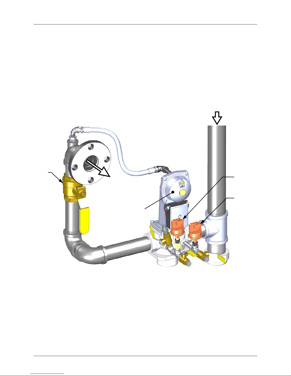
Benchmark 1500 - 2000 Boilers
NATURAL
GAS INLET
TO
VALVE
CHAPTER 3 – OPERATION
When there is a demand for heat, the following events will occur:
NOTE
If any of the Pre-Purge safety device switches are open, the
appropriate fault message will be displayed. Also, the appropriate
messages will be displayed throughout the start sequence, if the
required conditions are not observed.
1. The DEMAND LED status indicator will light.
2. The unit checks to ensure that the Proof of Closure (POC) switch in the downstream
Safety Shut-Off Valve (SSOV) is closed. See Figure 3-3 for SSOV location.
MANUAL
SHUT-OFF
VALVE
AIR/FUEL
SSOV
Figure 3-3:
BMK 1500/2000:
3. With all required safety device switches closed, a purge cycle will be initiated and the
following events will occur:
SSOV Location
HIGH GAS
PRESSURE
SWITCH
LOW GAS
PRESSURE
SWITCH
a. The Blower relay energizes and turns on the blower.
b. The Air/Fuel Valve rotates to the full-open purge position and closes purge position
switch. The dial on the Air/Fuel Valve (Figure 3-4) will read 100 to indicate that it is
full-open (100%).
Page 44 of 184 AERCO International, Inc. • 100 Oritani Dr. • Blauvelt, NY 10913 OMM-0097_0C
Ph.: 800-526-0288 GF-142
Page 45
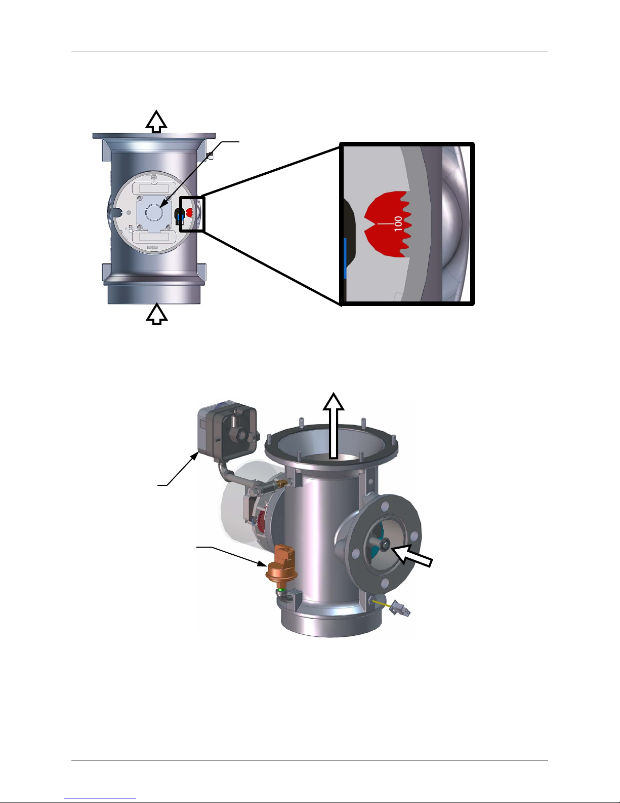
Benchmark 1500 - 2000 Boilers
STEPPER
MOTOR
TO BLOWER
AIR IN
AIR/FUEL VALVE
OUTLET TO BLOWER
BLOCKED
SWITCH
SWITCH
TRAIN
CHAPTER 3 – OPERATION
c. The VALVE POSITION bargraph will show 100%.
PURGE
VALVE POSITIO N
DIAL AT 100%
Figure 3-4: Air/Fuel Valve In Purge Position
4. Next, the blower proof switch on the Air/Fuel Valve (Figure 3-5) closes. The display will
show Purging and indicate the elapsed time of the purge cycle in seconds.
BLOWER
PROOF
AIR/FUEL VALVE
INLET FROM GAS
INLET
5. Upon completion of the purge cycle, the Control Box initiates an ignition cycle and the
following events occur:
(a) The Air/Fuel Valve rotates to the low-fire (Ignition Position) position and closes the
ignition switch. The Dial on the Air/Fuel Valve (Figure 3-6) will read between 25 and
35 to indicate that the valve is in the low fire position.
OMM-0097_0C AERCO International, Inc. • 100 Oritani Dr. • Blauvelt, NY 10913 Page 45 of 184
GF-142 Ph.: 800-526-0288
Figure 3-5: Blower Proof Switch
Page 46
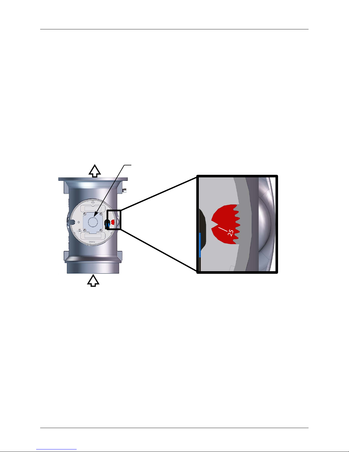
Benchmark 1500 - 2000 Boilers
TO BLOWER
AIR IN
STEPPER
MOTOR
CHAPTER 3 – OPERATION
(b) The “Spark Cycle Time” item in the Factory menu can be set to either 0 Sec, 2 Sec
or 7 Sec to define the duration of the Spark Element Cleaning Cycle. This cycle
turns on the spark transformer to produce a spark (with no gas flowing) to clean the
spark element of moisture or carbon buildup.
For the duration of this cycle, the C-More will display the “CLEANING IGNITER”
message.
(c) Following the Spark Element Cleaning Cycle, power is applied to the Gas Safety
Shut-off Valve (SSOV) and the C-More displays the “PRE IGNITION” message.
When the SSOV indicates the Gas Valve is OPEN (POC), the C-More displays the
“IGNITION TR IA L ” message.
(d) If no spark is present 3 seconds into the IGNITION TRIAL, the C-More will abort the
Ignition Cycle and shut down the boiler. Refer to Chapter 8: Troubleshooti ng for
guidance if this occurs.
IGNITION
VALVE POSITIO N
DIAL AT
25% to 35%
Figure 3-6: Air/Fuel Valve In Ignition Position
6. Up to 4 seconds will be allowed for ignition to be detected. The igniter relay will be turned
off one second after flame is detected.
7. After 2 seconds of continuous flame, Flame Proven will be displayed and the flame
strength will be indicated. After 5 seconds, the current date and time will be displayed in
place of the flame strength.
8. With the unit firing properly, it will be controlled by the temperature controller circuitr y. T he
boiler’s VALVE POSITION will be continuously displayed on the front panel bargraph.
Once the demand for heat has been satisfied, the Control Box will turn off the SSOV gas valve.
The blower relay will be deactivated and the Air/Fuel Valve will be closed. Standby will be
displayed.
Page 46 of 184 AERCO International, Inc. • 100 Oritani Dr. • Blauvelt, NY 10913 OMM-0097_0C
Ph.: 800-526-0288 GF-142
Page 47

Benchmark 1500 - 2000 Boilers
16% (Stop Level)
76,000
5.0%
20%
127,000
8.5%
30%
366,000
24.4%
40%
629,000
41.9%
50%
822,000
54.7%
60%
977,000
65.0%
70%
1,119,000
74.5%
80%
1,255,000
83.5%
90%
1,396,000
92.9%
100%
1,502,000
100%
16% (Stop Level)
100,000
6.7%
20%
143,000
11%
30%
388,000
23%
40%
759,000
37%
50%
1,069,000
51%
60%
1,283,000
61%
70%
1,476,000
74%
80%
1,675,000
83%
90%
1,833,000
93%
100%
2,000,000
100%
CHAPTER 3 – OPERATION
3.10 START/STOP LEVELS
The start and stop levels are the Air/Fuel Valve positions (% open) that start and stop the unit,
based on load. These levels are Factory preset as follows:
BMK 1500 BMK 2000
Start Level:
Stop Level:
24% 24%
16% 16%
Normally, these settings should not require adjustment.
Note that the energy input of the boiler is not linearly related to the Air/Fuel Valve position. Refer
to Table 3-7 for the relationship between the energy input and Air/Fuel Valve position for a BMK
1500 MBH boiler running on natural gas.
Table 3-7a:
BMK 1500:
Relationship Between Air/Fuel Valve Position and
Energy Input Running On Natural Gas
Air/Fuel Valve
Position
(% Open)
Energy Input
(BTU/Hr)
Boiler Energy Input
(% of Full Capacity)
Table 3-7b:
BMK 2000:
Energy Input Running On Natural Gas
Air/Fuel Valve
Position
(% Open)
OMM-0097_0C AERCO International, Inc. • 100 Oritani Dr. • Blauvelt, NY 10913 Page 47 of 184
GF-142 Ph.: 800-526-0288
Relationship Between Air/Fuel Valve Position and
Energy Input
(BTU/Hr)
Boiler Energy Input
(% of Full Capacity)
Page 48

Benchmark 1500 - 2000 Boilers
CHAPTER 3 – OPERATION
(This Page Is Intentionally Blank)
Page 48 of 184 AERCO International, Inc. • 100 Oritani Dr. • Blauvelt, NY 10913 OMM-0097_0C
Ph.: 800-526-0288 GF-142
Page 49

Benchmark 1500 - 2000 Boilers
WARNING
CHAPTER 4 – INITIAL START-UP
CHAPTER 4. INITIAL START-UP
4.1 INI TIAL START-UP REQUIREMENTS
The requirements for the initial start-up of the Benchmark boiler consists of the following:
• Complete installation (Chapter 2)
• Set proper controls and limits (Chapter 3)
• Perform combustion calibration (Chapter 4)
• Test safety devices (Chapter 6)
All applicable installation procedures in Chapter 2 must be fully com pleted prior to performing
the initial start-up of the unit. The initial start-up must be successfully completed prior to putting
the unit into service. Starting a unit without the proper piping, venting, or electrical systems can
be dangerous and may void the product warranty. The following start-up instructions should be
followed precisely in order to operate the unit safely and at a high thermal eff iciency, with low
flue gas emissions.
Initial unit start-up must be performed ONLY by AERCO factory trained start-up and service
personnel. After performing the start-up procedures in this Chapter, it will be necessary to
perform the Safety Device Testing procedures specified in Chapter 6 to complete all initial unit
start-up requir ements.
An AERCO Gas Fired Startup Sheet, included with each Benchmark, must be completed for
each unit for warranty validation and a copy must be returned promptly to AERCO at:
AERCO International, Inc.
100 Oritani Drive
Blauvelt, New York 10913
(FAX: 845-580-8090)
DO NOT AT TEMPT TO DRY FIRE THE UNIT . STARTING THE
UNIT WITHOUT A FULL WATER LEVEL CAN SERIOUSLY
DAMAGE THE UNIT AND MAY RESULT IN INJURY TO
PERSONNEL OR PROPERTY DA MAGE. THIS SITUATION WILL
VOID ANY WARRANTY.
NOTE
ALL APPLICABLE INSTALLATION PROCEDURES IN CHAPTER
2 MUST BE COMPLETED BEFORE ATTEMPTING TO START
THE UNIT.
4.2 TOOLS AND INSTRUMENTATION FOR COMBUSTION CALIBRATION
To properly perform combustion calibration, the proper instruments and tools must be used and
correctly attached to the unit. The following sections outline the necessary tools and
instrumentation as well as their installation.
OMM-0097_0C AERCO International, Inc. • 100 Oritani Dr. • Blauvelt, NY 10913 Page 49 of 184
GF-142 Ph.: 800-526-0288
Page 50
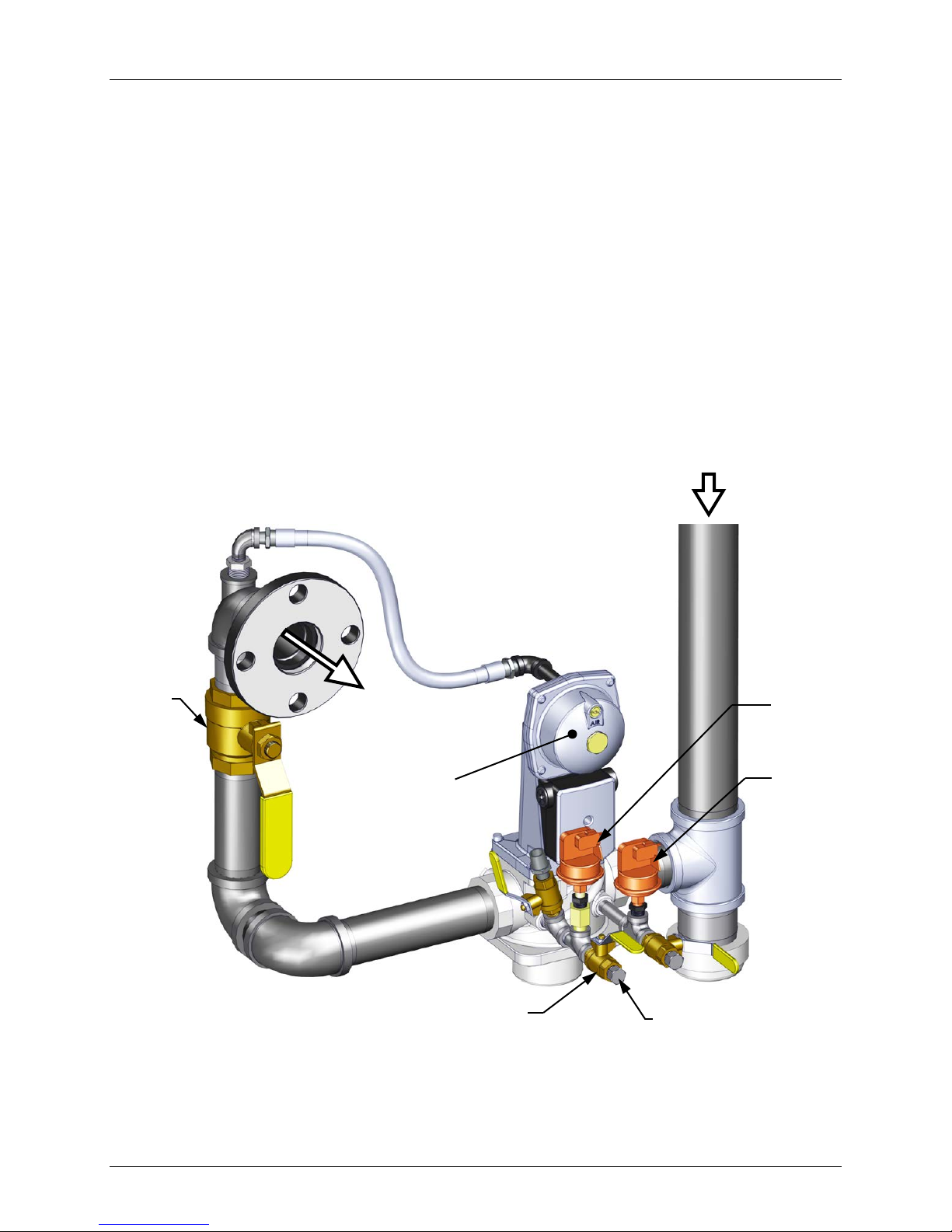
Benchmark 1500 - 2000 Boilers
NATURAL
GAS INLET
VALVE
LEAK DETECTION
BALL VALVE
CHAPTER 4 – INITIAL START-UP
4.2.1 Required Tools & Instrumentation
The following tools and instrumentation are necessary to perform combustion calibration of the
unit:
• Digital Com bustion Analyzer: Oxygen accuracy to ± 0.4%; Carbon Monoxide (CO) and
Nitrogen Oxide (NOx) resolution to 1PPM.
• 16 inch W.C. manometer or equivalent gauge and plastic tubing.
• 1/4 inch NPT-to-barbed fittings for use with gas supply manometer or gauge.
• Small and large flat blade screwdrivers.
• Tube of silicone adhesive
4.2.2 Installing Gas Supply Manometer
The gas supply manometer (or gauge) is used to monitor the gas pressure on the downstream
side of the SSOV during the Combustion Calibration procedures described in section 4.3.
The gas supply manometer is installed at the upstream and/or downstream location shown in
Figure 4-1.
MANUAL
SHUT-OFF
VALVE
TO
AIR/FUEL
SSOV
HIGH GAS
PRESSURE
SWITCH
LOW GAS
PRESSURE
SWITCH
Figure 4-1: BMK 1500/2000: 1/4 Inch Gas Plug Location for Combustion
Page 50 of 184 AERCO International, Inc. • 100 Oritani Dr. • Blauvelt, NY 10913 OMM-0097_0C
Ph.: 800-526-0288 GF-142
Calibration
1/4” NPT PLUG
(Install manometer here for
Combustion Calibration)
Page 51
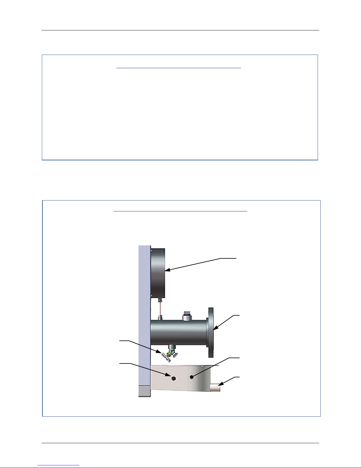
Benchmark 1500 - 2000 Boilers
EXHAST MANIFOLD
AIR INLET
ANALYZER PORT
CONDENSATE DRAIN
DR AIN VALV E
CHAPTER 4 – INITIAL START-UP
Install the 16” W.C. manometer(s) as described in the following steps:
Installing Gas Supply Manom eter
1. Turn off the main gas supply upstream of the unit.
2. Remove the top panel and front panel from the boiler to access the gas train
components.
3. To monitor the gas pressure on the downstream side of the SSOV during Combustion
Calibration (section 4.3), remove the 1/4” NPT plug from the leak detection ball valve on
the downstream side of the SSOV as shown in Figure 4-1.
4. Install a NPT-to-barbed fitting into the tapped plug port.
5. Attach one end of the plastic tubing to the barbed fitting and the other end to the 16” W.C.
manometer.
4.2.3 Accessing the Analyzer Probe Port
The unit contains a 1/4” NPT port on the side of t he exhaust manifold as shown in Figure 4-2.
Prepare the port for the combustion analyzer probe as follows:
Accessing the Analyzer Probe Port
1. Refer to Figure 4-2 and remove the 1/4” NPT plug from the exhaust manifold.
2. If necessary, adjust the stop on the combustion analyzer probe so it will extend mid-way
into the flue gas flow. DO NOT install the probe at this time.
PRIMARY HOT
WATER INLET
Figure 4-2: Analyzer Probe Port Location (Right Side Partial View)
OMM-0097_0C AERCO International, Inc. • 100 Oritani Dr. • Blauvelt, NY 10913 Page 51 of 184
GF-142 Ph.: 800-526-0288
Page 52

Benchmark 1500 - 2000 Boilers
CHAPTER 4 – INITIAL START-UP
4.3 NATURAL GAS COMBUSTION C ALIBR ATION
The Benchmark boiler is combustion calibrated at the factory prior to shipping. This gas
pressure must be within the following ranges for each model of boiler at full fire:
BMK Boiler Model Nominal Gas Pressure
BMK 1500
BMK 2000
3.6” W.C. ±0.2” W.C.
3.9” W.C. ±0.2” W.C.
Recalibration as part of initial start-up is necessary due to changes in the local altitude, gas BTU
content, gas supply piping and supply regulators. Combustion Calibration Test Data sheets ar e
shipped with each unit. These sheets must be filled out and returned to AERCO for proper
Warranty Validation.
It is important to perform the following procedure as outlined. This will keep readjustments to a
minimum and provide optimum performance.
Instructions for natural gas combustion calibration follow, with the BMK 1500 instructions f irst,
followed by the BMK 2000 instructions.
4.3.1 BMK 1500 Natural Gas Combustion Calibration
1. Open the water supply and return valves to the unit and ensure that the system pumps
are running.
2. Open the natural gas supply valve to the unit.
3. Set the control panel ON/OFF switch to the OFF position
4. Turn on external ac power to the unit. The display will show loss of power and the t ime
and date.
5. Set the unit to the manual mode by pressing the AUTO/MAN key. A flashing manual
valve position message will be displayed with the present position in %. Also, the
MANUAL LED will light.
6. Adjust the air/fuel valve position to 0% by pressing the ▼ arrow key.
7. Ensure that the leak detection ball valve downstream of the SSOV is open.
8. Set the ON/OFF switch to the ON position.
9. Change the valve position to 30% using the ▲ arrow key. The unit should begin its start
sequence and fire.
10. Next, verify that the gas pressure downstream of the SSOV is set to 3.6 ± 0.2” W.C. If
gas pressure adjustment is required, remove the brass hex nut on the SS OV actuator to
access the gas pressure adjustment screw (Figure 4-3). Make gas pr essure adjustments
using a flat-tip screwdriver to obtain a gas pressure approximately 3.6” W.C. ± 0.2” W.C.
11. Using the ▲ arrow key, increase the valve open position to 100%. Verify that the gas
pressure on the downstream side of the SSOV settles within the range of 3.6 ± 0.1” W.C.
Readjust the gas pressure if necessary.
12. With the valve position at 100%, insert the combustion analyzer probe into the flue probe
opening and allow enough time for the combustion analyzer reading to stabilize.
Page 52 of 184 AERCO International, Inc. • 100 Oritani Dr. • Blauvelt, NY 10913 OMM-0097_0C
Ph.: 800-526-0288 GF-142
Page 53

Benchmark 1500 - 2000 Boilers
CHAPTER 4 – INITIAL START-UP
BMK 1500 Natural Gas Combustion Calibration (Cont.)
13. Compare the oxygen readings on the combustion analyzer to the on-board O2 sensor
value displayed in the Operating Menu of the C-More Control Panel. If the values differ by
more than ±0.5%, have your combustion analyzer calibration checked as soon as
possible. If the readings differ by more than ±1.5%, use the on-board O
calibrate the unit. Have your combustion analyzer serviced.
14. Compare the measured oxygen level to the oxygen range shown below. Also, ensure that
the nitrogen oxide (NOx) and carbon monoxide (CO) readings do not exceed the values
shown. If you are not in a “NOx-limited” area and/or do not have a NOx measurement in
your analyzer, set the oxygen (O
) at 5.5% ± 0.5%.
2
Combustion Calibration Readings – 100% valve Position
Valve Position Oxygen (O2) % Nitrogen Oxide (NOx) Carbon Monoxide (CO)
100% 5.0% - 6.0% ≤20 ppm <100 ppm
15. If the oxygen level is not within the required tolerance, the gas pressure on the
downstream side of the SSOV must be adjusted using the gas pressure adjustment
screw on the SSOV (Figure 4-3). Slowly rotate the gas pressure adjustment
(approximately 1/4-turn increments). Allow the combustion analyzer to stabilize follo wing
each adjustment. Clockwise rotation reduces the oxygen level, while counterclockwise
rotation increases the oxygen level.
sensor to
2
16. Once the oxygen level is within the specified range at 100%, record the O
, NOx and CO
2
readings on the Combustion Calibration Data Sheets provided with the unit.
17. Lower the valve position to 80% using the ▼arrow key.
NOTE
The remaining combustion calibration steps are performed using
the Combustion Cal Menu included in the C-More Control System.
The combustion calibration control functions will be used to adjust
the oxygen level (%) at valve positions of 80%, 60%, 45%, 30%
and 16% as described in the following steps. These steps assume
that the inlet air temperature is within the range of 50°F to 100°F.
If NOx readings exceed the target values shown, increase the O
level up to 1% higher than the listed calibration range. Record the
increased O
value on the Combustion Calibration sheet.
2
18. Press the MENU key on the front panel of the C-MORE and access the Setup menu.
Enter password 6817 and then press the ENTER key.
19. Press the MENU key on the front panel of the C-MORE until Combustion Cal Menu
appears on the display.
20. Press the ▲ arrow key until SET Valve Position appears on the display.
21. Press the CHANGE key. SET Valve Position will begin to flash.
22. Press the ▲ arrow key until the SET Valve Position reads 80%. Press the ENTER key.
2
23. Next, press the down (▼) arrow key until CAL Voltage 80% is displayed.
24. Press the CHANGE key and observe that CAL Voltage 80% is flashing.
OMM-0097_0C AERCO International, Inc. • 100 Oritani Dr. • Blauvelt, NY 10913 Page 53 of 184
GF-142 Ph.: 800-526-0288
Page 54
Benchmark 1500 - 2000 Boilers
CHAPTER 4 – INITIAL START-UP
BMK 1500 Natural Gas Combustion Calibration (Cont.)
25. The oxygen level at the 80% valve position should be as shown below. Also, ensure that
the nitrogen oxide (NOx) and carbon monoxide (CO) readings do not exceed the
following values:
Combustion Calibration Readings – 80% valve Position
Valve Position Oxygen (O2) % Nitrogen Oxide (NOx) Carbon Monoxide (CO)
80% 5.9% ± 0.5% ≤20 ppm <100 ppm
26. If the oxygen level is not within the specified range, adjust the level using the ▲ and ▼
arrow keys. This will adjust the output voltage to the blower motor as indicated on the
display. Pressing the ▲ arrow key increases the oxygen level and pressing the down ▼
arrow key decreases the oxygen level.
27. Once the oxygen level is within the specified range at 80%, press the ENTER key to
store the selected blower output voltage for the 80% valve posit ion. Record all readings
on the Combustion Calibration Sheets provided.
28. Repeat steps 20 through 27 for valve positions of 60%, 45%, 30% and 16%. The oxygen
(O
), nitrogen oxide (NOx) and carbon monoxide (CO) should remain within the same
2
limits for all valve positions as shown in the following table.
NOTE
If NOx readings exceed the target values shown (<20 ppm),
increase the O
range shown in the table. Record the increased O
level up to 1% higher than the listed calibration
2
value on the
2
Combustion Calibration sheet.
Combustion Calibration Readings
Valve Position Oxygen (O2) % Nitrogen Oxide (NOx) Carbon Monoxide (CO)
60% 6.0% ± 0.5 <20 ppm <100 ppm
45% 6.3% ± 0.5 <20 ppm <100 ppm
30% 6.3% ± 0.5 <20 ppm <100 ppm
16% 6.0% ± 0.5 <20 ppm <100 ppm
29. If the oxygen level at the 16% valve position is too high and the Blower voltage is at the
minimum value, you can adjust the idle screw (TAC valve) which is recessed in the top of
the Air/Fuel Valve (see Figure 4-4). Rotate the screw 1/2 turn clockwise (CW) to add fuel
and reduce the O
60% down to 16% after making a change to the idle screw (TAC valve).
30. This completes the BMK 1500 Natural Gas combustion calibration procedures.
to the specified level. Recalibration MUST be performed again from
2
Page 54 of 184 AERCO International, Inc. • 100 Oritani Dr. • Blauvelt, NY 10913 OMM-0097_0C
Ph.: 800-526-0288 GF-142
Page 55
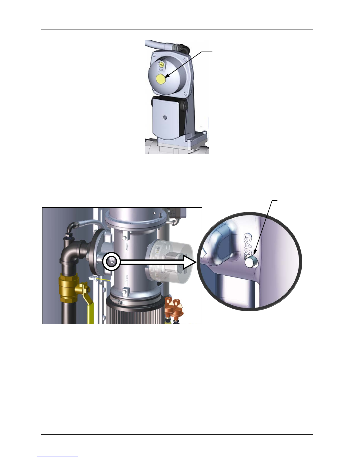
Benchmark 1500 - 2000 Boilers
BRASS HEX HEAD
CHAPTER 4 – INITIAL START-UP
(Remove to access
the Gas Pressure
Adjustment Screw).
Figure 4-3: Gas Pressure Adjustment Screw Location
TAC VALVE
IDLE SCREW
Figure 4-4: TAC Valve Adjust (Idle Screw)
OMM-0097_0C AERCO International, Inc. • 100 Oritani Dr. • Blauvelt, NY 10913 Page 55 of 184
GF-142 Ph.: 800-526-0288
Page 56

Benchmark 1500 - 2000 Boilers
CHAPTER 4 – INITIAL START-UP
4.3.2 BMK 2000 Natural Gas Combustion Calibration
1. Open the water supply and return valves to the unit and ensure that the system pumps
are running.
2. Open the natural gas supply valve to the unit.
3. Set the control panel ON/OFF switch to the OFF position
4. Turn on external ac power to the unit. The display will show loss of power and the t ime
and date.
5. Set the unit to the manual mode by pressing the AUTO/MAN key. A flashing manual
valve position message will be displayed with the present position in %. Also, the
MANUAL LED will light.
6. Adjust the air/fuel valve position to 0% by pressing the ▼ arrow key.
7. Ensure that the leak detection ball valve downstream of the SSOV is open.
8. Set the ON/OFF switch to the ON position.
9. Change the valve position to 30% using the ▲ arrow key. The unit should begin its start
sequence and fire.
10. Next, verify that the gas pressure downstream of the SSOV is set to 3.9 ± 0.2” W.C. If
gas pressure adjustment is required, remove the brass hex nut on the SS OV actuator to
access the gas pressure adjustment screw (Figure 4-3). Make gas pr essure adjustments
using a flat-tip screwdriver to obt ain a gas pressure within the range of 3.9” W.C. ± 0.2”
W.C.
11. Using the ▲ arrow key, increase the valve open position to 100%. Verify that the gas
pressure on the downstream side of the SSOV settles within the range of 3.9 ± 0.2” W.C.
Readjust the gas pressure if necessary.
12. With the valve position at 100%, insert the combustion analyzer probe into the flue probe
opening and allow enough time for the combustion analyzer reading to stabilize.
13. Compare the oxygen readings on the combustion analyzer to the on-board O
sensor
2
value displayed in the Operating Menu of the C-More Control Panel. If the values differ by
more than ±0.5%, have your combustion analyzer calibration checked as soon as
possible. If the readings differ by more than ±1.5%, use the on-board O
sensor to
2
calibrate the unit. Have your combustion analyzer serviced.
14. Compare the measured oxygen level to the oxygen range shown below. Also, ensure that
the nitrogen oxide (NOx) and carbon monoxide (CO) readings do not exceed the values
shown. If you are not in a “NOx-limited” area and/or do not have a NOx measurement in
your analyzer, set the oxygen (O
) at 5.5% ± 0.5%.
2
Combustion Calibration Readings – 100% valve Position
Valve Position Oxygen (O2) % Nitrogen Oxide (NOx) Carbon Monoxide (CO)
100% 5.0% - 6.0% ≤20 ppm <100 ppm
Page 56 of 184 AERCO International, Inc. • 100 Oritani Dr. • Blauvelt, NY 10913 OMM-0097_0C
Ph.: 800-526-0288 GF-142
Page 57

Benchmark 1500 - 2000 Boilers
CHAPTER 4 – INITIAL START-UP
BMK 2000 Natural Gas Combustion Calibration (Cont.)
15. If the oxygen level is not within the required tolerance, the gas pressure on the
downstream side of the SSOV must be adjusted using the gas pressure adjustment
screw on the SSOV (Figure 4-3). Slowly rotate the gas pressure adjustment
(approximately 1/4-turn increments). Allow the combustion analyzer to stabilize following
each adjustment. Clockwise rotation reduces the oxygen level, while counterclockwise
rotation increases the oxygen level.
16. Once the oxygen level is within the specified range at 100%, record the O
, NOx and CO
2
readings on the Combustion Calibration Data Sheets provided with the unit.
17. Lower the valve position to 80% using the ▼arrow key.
NOTE
The remaining combustion calibration steps are performed using
the Combustion Cal Menu included in the C-More Control System.
The combustion calibration control functions will be used to adjust
the oxygen level (%) at valve positions of 80%, 50%, 40%, 30%
and 14% as described in the following steps. These steps assume
that the inlet air temperature is within the range of 50°F to 100°F.
If NOx readings exceed the target values shown, increase the O
level up to 1% higher than the listed calibration range. Record the
increased O
value on the Combustion Calibration sheet.
2
18. Press the MENU key on the front panel of the C-MORE and access the Setup menu.
Enter password 6817 and then press the ENTER key.
19. Press the MENU key on the front panel of the C-MORE until Combustion Cal Menu
appears on the display.
20. Press the ▲ arrow key until SET Valve Position appears on the display.
21. Press the CHANGE key. SET Valve Position will begin to flash.
2
22. Press the ▲ arrow key until the SET Valve Position reads 80%. Press the ENTER key.
23. Next, press the down (▼) arrow key until CAL Voltage 80% is displayed.
24. Press the CHANGE key and observe that CAL Voltage 80% is flashing.
25. The oxygen level at the 80% valve position should be as shown below. Also, ensure that
the nitrogen oxide (NOx) and carbon monoxide (CO) readings do not exceed the
following values:
Combustion Calibration Readings @ 80% Valve Position
Valve Position Oxygen (O2) % Nitrogen Oxide (NOx) Carbon Monoxide (CO)
80% 5.9% ± 0.5% ≤20 ppm <100 ppm
26. If the oxygen level is not within the specified range, adjust the level using the ▲ and ▼
arrow keys. This will adjust the output voltage to the blower motor as indicated on the
display. Pressing the ▲ arrow key increases the oxygen level and pressing the down ▼
arrow key decreases the oxygen level.
OMM-0097_0C AERCO International, Inc. • 100 Oritani Dr. • Blauvelt, NY 10913 Page 57 of 184
GF-142 Ph.: 800-526-0288
Page 58
Benchmark 1500 - 2000 Boilers
CHAPTER 4 – INITIAL START-UP
BMK 2000 Natural Gas Combustion Cali bration (Cont.)
27. Once the oxygen level is within the specified range at 80%, press the ENTER key to
store the selected blower output voltage for the 80% valve position. Record all readings
on the Combustion Calibration Sheets provided.
28. Repeat steps 20 through 27 for valve positions of 80%, 50%, 40%, 30% and 14%. The
oxygen (O
same limits for all valve positions as shown in the following table.
Valve Position Oxygen (O2) % Nitrogen Oxide (NOx) Carbon Monoxide (CO)
60% 6.0% ± 0.5 <20 ppm <100 ppm
), nitrogen oxide (NOx) and carbon monoxide (CO) should remain within the
2
NOTE
If NOx readings exceed the target values shown (<20 ppm),
increase the O
range shown in the table. Record the increased O
level up to 1% higher than the listed calibration
2
value on the
2
Combustion Calibration sheet.
Combustion Calibration Readings
45% 6.3% ± 0.5 <20 ppm <100 ppm
30% 6.3% ± 0.5 <20 ppm <100 ppm
16% 6.0% ± 0.5 <20 ppm <100 ppm
29. If the oxygen level at the 14% valve position is too high and the Blower voltage is at the
minimum value, you can adjust the idle screw (TAC valve) which is recessed in the top of
the Air/Fuel Valve (see Figure 4-4). Rotate the screw 1/2 turn clockwise (CW) to add fuel
and reduce the O
to the specified level. Recalibration MUST be performed again from
2
60% down to 16% after making a change to the idle screw (TAC valve).
30. This completes the BMK 2000 Natural Gas combustion calibration procedures.
4.4 REASSEMBLY
Once the combustion calibration adjustments are properly set, the unit can be reassembled for
service operation.
Reassembly
1. Set the ON/OFF switch in the OFF position.
2. Disconnect AC power from the unit.
3. Shut off the gas supply to the unit.
4. Remove the manometer and barbed fittings and reinstall the NPT plug using a suitable
pipe thread compound.
5. Remove the combustion analyzer probe from the 1/4” vent hole in the exhaust manifold.
Replace the 1/4” NPT plug in the manifold.
6. Replace all previously removed sheet metal enclosures on the unit.
7. This concludes reassembly of the unit after combustion calibration.
Page 58 of 184 AERCO International, Inc. • 100 Oritani Dr. • Blauvelt, NY 10913 OMM-0097_0C
Ph.: 800-526-0288 GF-142
Page 59
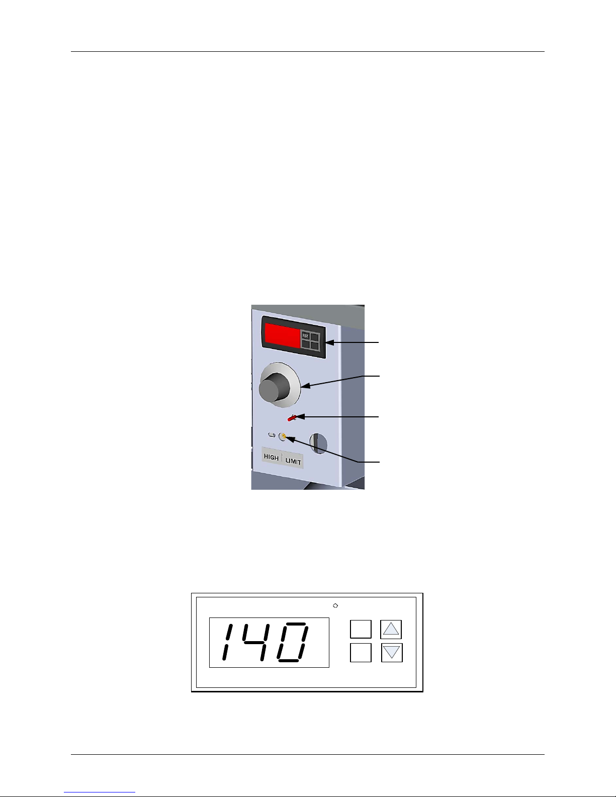
Benchmark 1500 - 2000 Boilers
F
Alarm
RST
SET
Limit Control
DIGITAL OVER-TEMPERATURE
ADJUSTABLE TEMPERATURE
LIMIT SWITCH
RESET BUTTON FOR MANUAL
MANUAL TEMPERATURE LIMIT
CHAPTER 4 – INITIAL START-UP
4.5 OVER-TEMPERATURE LIMIT SWITCHES
The unit contains three (3) types of over-temperature limit switches. These switches consist of a
manual reset switch, a rotary dial adjustable switch and a digital alarm switch. These switches
are mounted on a plate as shown in Figure 4-5. The switches can be accessed by opening the
front panel door of the unit.
The manual reset switch is not adjustable and is permanently fixed at 210°F. T his switch will
shut down and lock out the boiler if the water temperature exceeds 210°F. Following an overtemperature condition, it must be manually reset by pressing the manual reset button shown in
Figurer 4-5 before the boiler can be restarted.
The rotary dial over-temperature switch is manually adjustable f rom xxx to yyy ºF. This switch
allows the boiler to restart, once the temperature drops below the selected tempe rature s etting
on the dial. Set the dial on this over-temperature switch to the desired setting.
The digital alarm switch shown in Figures 4-5 and 4-6 is preset at the factory to 210ºF and
should not be changed. If an over-temperature condition is detected, this switch autom atically
shuts down the boiler and sounds an audible alarm. If desired, the over-temperature alarm
switch settings can be checked or adjusted using the procedure in section 4.5.1.
ALARM SWIT CH
TEMPERATURE LIMIT SWITCH
SWITCH
Figure 4-5: Over-Temperature Limit Switch Locations
4.5.1 Digital Alarm Switch Checks and A dj u st ments
The digital alarm switch settings can be checked or adjusted using the controls and display on
the front panel of the switch illustrated and described in Figure 4-6 and Table 4-1.
OMM-0097_0C AERCO International, Inc. • 100 Oritani Dr. • Blauvelt, NY 10913 Page 59 of 184
GF-142 Ph.: 800-526-0288
Figure 4-6: Digital Over-Temperature Alarm Switch Front Panel
Page 60
Benchmark 1500 - 2000 Boilers
CONTROL OR
DISPLAY
CHAPTER 4 – INITIAL START-UP
Table 4-1: Digital Alarm Switch Controls and Display
MEANING FUNCTION
LED Display
RST
SET
TEMP status
RESET Button Resets the unit after an alarm condition.
UP Button Increases the displayed temperature.
DOWN Button Decreases the displayed temperature.
SET Button
Displays current water temperature or
setpoint.
Used to access and store parameters in the
unit.
Perform the following steps to check or adjust the digital alarm switch settings:
Digital Alarm Settings
1. Set the ON/OFF to the ON position.
2. Press the SET button on the Digital Alarm Switch. SP will appear in the display.
3. Press the SET button again. The current over-temperature limit value stored in memory will
be displayed. (default = 210°F).
4. If the display does not show the required over-temperature alarm setting, press the ▲ or ▼
arrow button to change the display to the desired temperature setting.
5. Once the desired over-temperature alarm setting (210ºF) is displayed, press the SET button
to store the setting i n memory .
6. To calibrate the offset (P1), press and hold the SET button for 8 seconds on the Digital
Alarm Switch. Access code value 0 should appear in the display. The switch comes from the
factory with the code set at 0. AERCO recommends that you do not change this code.
7. Press the SET but ton again to enter the code. The first parameter label (SP) will appear in
the display.
8. Using the ▲ and ▼ arrow keys, select parameter P1.
9. Press SET to view the value stored in memory.
10. If the desired value is not displayed, modify the setting using the ▲ and ▼ arrow keys. The
value can be changed from -10° to +10° offset. Press SET to enter the value and exit to the
text parameter.
11. To exit the programming mode, press the SET and ▼ buttons simultaneously, or simply wait
one minute and the display will automatically exit the programming mode.
12. Once the programming mode has been exited, the display will show the current outlet water
temperature of the boiler.
Page 60 of 184 AERCO International, Inc. • 100 Oritani Dr. • Blauvelt, NY 10913 OMM-0097_0C
Ph.: 800-526-0288 GF-142
Page 61

Benchmark 1500 - 2000 Boilers
CHAPTER 5 – MODE OF OPERATION
CHAPTER 5. MODE OF OPERATION
5.1 INTRODUCTION
The boiler is capable of being operated in any one of six different modes. The following sections
in this Chapter provide descriptions of each of these operating modes. Each boiler is shipped
from the factory tested and configured for the ordered mode of operation. All temperature
related parameters are at their factory default values which work well in most applications.
However, it may be necessary to change certain parameters to customize the unit to the system
environment. A complete listing and descriptions of the temperature related parameters are
included in Appendix A. Factory defaults are listed in Appendix D. After reading this chapter,
parameters can be customized to suit the needs of the specific application.
5.2 INDOOR/OUTDOOR RESET MODE
This mode of operation is based on outside air temperatures. As the out side air temperature
decreases, the supply header temperature will increase and vice versa. For this mode, it is
necessary to install an outside air sensor as well as select a building reference temperature and
a reset ratio.
5.2.1 Reset Ratio
Reset ratio is an adjustable number from 0.1 to 9.9. Once adjusted, the supply header
temperature will increase by that number for each degree that the outside air temperature
decreases. For instance, if a reset ratio of 1.6 is used, for each degree that outside air
temperature decreases the supply header temperature will increase by 1.6 degrees.
5.2.2 Building Reference Temperature
This is a temperature from 40°F to 230°F. Once selected, it is the temperature that the system
references to begin increasing its temperature. For instance, if a reset ratio of 1.6 is used, and
we select a building reference temperature of 70°F, then at an outside temperature of 69°F, the
supply header temperature will increase by 1.6° to 71.6°F.
5.2.3 Outdoor Air Temperature Sensor Installation
The outdoor air temperature sensor must be mounted on the North side of the building in an
area where the average outside air temperature is expected. The sensor must be shielded from
the sun's direct rays, as well as direct impingement by the elements. If a cover or shield is used,
it must allow free air circulation. The sensor may be mounted up to two hundred feet from the
unit. Sensor connections are made at the Input/Output (I/O) Box on the front of the boiler.
Connections are made at the terminals labeled OUTDOOR AIR IN and AIR SENSOR COM
inside the I/O Box. Use shielded 18 to 22 AWG wire for connections. A wiring diagram is
provided on the cover of the I/O Box. Refer to Chapter 2, section 2.9.1 for additional wiring
information.
5.2.4 Indoor/Outdoor Startup
Startup in the Indoor/Outdoor Reset Mode is accomplished as follows:
A design engineer typically provides design outdoor air
temperature and supply header temperature data
OMM-0097_0C AERCO International, Inc. • 100 Oritani Dr. • Blauvelt, NY 10913 Page 61 of 184
GF-142 Ph.: 800-526-0288
NOTE
Page 62

Benchmark 1500 - 2000 Boilers
Menu Option
CHAPTER 5 – MODE OF OPERATION
Indoor/Outdoor Start up
1. Refer to the Indoor/Outdoor reset ratio charts in Appendix F.
2. Choose the chart corresponding to the desired Building Reference Temperature.
3. Go down the left column of the chart to the coldest design outdoor air temperature
expected in your area.
4. Once the design outdoor air temperature is chosen, go across the chart to the desired
supply header temperature for the design temperature chosen in step 3.
5. Next, go up that column to the Reset Ratio row to find the corresponding reset ratio.
6. Access the Configuration Menu and scroll through it until the display shows Bldg Ref
Temp. (Building Reference Temperature). If necessary, refer to section 3.3 for detailed
instructions on menu changing.
7. Press the CHANGE key. The display will begin to flash.
8. Use the ▲ and ▼ arrow keys to select the desired Building Reference Temperature.
9. Press ENTER to save any changes.
10. Next, scroll through the Configuration Menu until the display shows Reset Ratio.
11. Press the CHANGE key. The display will begin to flash.
12. Use the ▲ and ▼ arrow keys to select the Reset Ratio determined in step 5.
13. Press ENTER to save the change. This completes
5.3 CONSTANT SETPOINT MODE
The Constant Setpoint mode is used when a fixed header temperature is desired. Common
uses of this mode of operation include water source heat pump loops, and indirect heat
exchangers for potable hot water systems or processes.
No external sensors are required to operate in this mode. While it is necessary to set the
desired setpoint temperature, it is not necessary to change any other temperature-related
functions. The unit is factory preset with settings that work well in most applications. Prior to
changing any temperature-related parameters, other than the setpoint, it is suggested that an
AERCO representative be contacted. For descriptions of temperature-related functions and
their factory defaults, see Appendices A and E.
5.3.1 Setting the Setpoint
The setpoint temperature of the unit is adjustable from 40°F to 240°F. To set the unit for
operation in the Constant Setpoint Mode, the following menu settings must be made in the
Configuration Menu:
Boiler Mode Constant Setpoint
Internal Setpt Select desired setpoint using ▲ and ▼ arrow keys (40°F to 240°F)
Refer to section 3.3 for detailed instructions on changing menu options.
Page 62 of 184 AERCO International, Inc. • 100 Oritani Dr. • Blauvelt, NY 10913 OMM-0097_0C
Ph.: 800-526-0288 GF-142
Setting
Page 63

Benchmark 1500 - 2000 Boilers
Menu Option
Setting
CHAPTER 5 – MODE OF OPERATION
5.4 REMOTE SETPOINT MODES
The unit’s setpoint can be remotely controlled by an Energy Management System (EMS) or
Building Automation System (BAS). The Remote Setpoint can be driven by a current or voltage
signal within the following ranges:
• 4-20 mA/1-5 Vdc
• 0-20 mA/0-5 Vdc
The factory default setting for the Remote Setpoint mode is 4 - 20 mA/1 - 5 Vdc. With this
setting, a 4 to 20 mA/1 to 5 Vdc signal, sent by an EMS or BAS, is used to chang e the unit's
setpoint. The 4 mA/1V signal is equal to a 40°F setpoint while a 20 mA /5V signal is equal to a
240°F setpoint. When a 0 to 20 mA/0 to 5 Vdc signal is used, 0 mA is equal to a 40°F setpoint.
In addition to the current and voltage signals described above, the Remote Setpoint mode can
also driven by a RS-485 Modbus Network signal from an EMS or BAS.
The Remote Setpoint modes of operation can be used to drive single as well as multiple units.
NOTE
If a voltage, rather than current signal is used to control the
remote setpoint, a DIP switch adjustment must be made on the
PMC Board located in the Control Panel Assembly. Contact your
local AERCO representative for details.
In order to enable the Remote Setpoint Mode, the following menu setting must be made in the
Configuration Menu:
Boiler Mode Remote Setpoint
Remote Signal 4-20mA/1-5V, 0-20mA/0-5V, or Network
Refer to section 3.3 for detailed instructions on changing menu options.
If the Network setting is selected for RS-485 Modbus operation, a valid Comm Address must be
entered in the Setup Menu. Refer to Modbus Communication Manual GF-114 for additional
information.
While it is possible to change the settings of temperature related functions, the unit is factory
preset with settings that work well in most applications. It is suggested that an AERCO
representative be contacted, prior to changing any temperature related function settings. For
descriptions of temperature-related functions and their factory defaults, refer to Appendices A
and E.
5.4.1 Remote Setpoint Field Wiring
The only wiring connections necessary for the Remote Setpoint mode are connection of the
remote signal leads from the source to the unit’s I/O Box. The I/O Box is located on the front
panel of the boiler. For either a 4-20mA/0-5V or a 0-20mA/0-5V setting, the connections are
made at the ANALOG IN terminals in the I/O Box. For a Network setting, the connections are
made at the RS-485 COMM terminals in the I/O Box. The signal must be f loat ing, (ungr ounded)
at t he I/O Box and the wire used must be a two wire shielded pair from 18 to 22 AWG. Polarity
must be observed. The source end of the shield must be connected at the source. When driving
multiple units, each unit’s wiring must conform to the above.
OMM-0097_0C AERCO International, Inc. • 100 Oritani Dr. • Blauvelt, NY 10913 Page 63 of 184
GF-142 Ph.: 800-526-0288
Page 64

Benchmark 1500 - 2000 Boilers
Menu Option
Setting
Boiler Mode
Direct Drive
CHAPTER 5 – MODE OF OPERATION
5.4.2 Remote Setpoint Startup
Since this mode of operation is factory preset and the setpoint is being externally controlled, no
startup instructions are necessary. In t his mode, the REMOTE LED will light when the external
signal is present.
To operate the unit in the Manual mode, press the AUTO/MAN switch. The REMOTE LED will
go off and the MANUAL L ED will light.
To change back to the Remote Setpoint mode, simply press the AUTO/MAN switch. The
REMOTE LED will again light and the MANUAL LED will go off.
5.5 DIRECT DRIVE MODES
The unit’s air/fuel valve position (% open) can be changed by a remote signal which is typically
sent from an Energy Management System (EMS) or from a Building Automation System (BAS).
The Direct Drive mode can be driven by a current or voltage signal within the following ranges:
• 4-20 mA/1-5 Vdc
• 0-20 mA/0-5 Vdc
The factory default setting for the Direct Drive mode is 4-20 mA/1-5 Vdc. With this setting, a 4
to 20 mA signal, sent by an EMS or BAS is used to change the unit’s valve position from 0% to
100%. A 4 mA/1V signal is equal to a 0% valve position, while a 20 mA /5V signal is equal t o a
100% valve position. When a 0-20 mA/0-5 Vdc signal is used, zero is equal to a 0% valve
position.
In addition to the current and voltage signals described above, the Direct Drive mode can also
driven by a RS-485 Modbus Network signal from an EMS or BAS.
When in a Direct Drive mode, the unit is a slave to the EMS or BAS and does not have a role in
temperature control. Direct Drive can be used to drive single, or multiple units.
NOTE
If a voltage, rather than current signal is used to control the
remote setpoint, a DIP switch adjustment must be made on the
CPU Board located in the Control Box Assembly. Contact your
local AERCO representative for details.
To enable the Direct Drive Mode, the following menu setting must be made in the Conf iguration
Menu:
Remote Signal 4-20mA/1-5V, 0-20mA/0-5V, or Network
Refer to section 3.3 for instructions on changing menu options.
If the Network setting is selected for RS-485 Modbus operation, a valid Comm Address must be
entered in the Setup Menu. Refer to Modbus Communication Manual GF-114 for additional
information.
Page 64 of 184 AERCO International, Inc. • 100 Oritani Dr. • Blauvelt, NY 10913 OMM-0097_0C
Ph.: 800-526-0288 GF-142
Page 65

Benchmark 1500 - 2000 Boilers
Menu Option
Setting
CHAPTER 5 – MODE OF OPERATION
5.5.1 Direct Drive Field Wiring
The only wiring connections necessary for Direct Drive mode are connection of the remote
signal leads from the source to the unit’s I/O Box. For either a 4-20mA/0-5V or a 0-20mA/0-5V
setting, the connections are made at the ANALOG IN terminals in the I/O Box. For a Network
setting, the connections are made at the RS-485 COMM terminals in the I/O Box. The signal
must be floating, (ungrounded) at the I/O Box and the wire used must be a two wire shielded
pair from 18 to 22 AWG. Polarity must be observed. The source end of the shield must be
connected at the source. When driving multiple units, each unit’s wiring must conform to the
above.
5.5.2 Direct Drive Startup
Since this mode of operation is factory preset and the valve position is being externally
controlled, no startup instructions are necessary. In this mode, the REMOTE LED will l ight when
the signal is present.
To operate the unit in manual mode, press the AUTO/MAN switch. The REMOTE LED will go
off and the MANUAL LED will ligh t.
To c hange back to the Direct Drive mode, simply press the AUTO/MAN s witch. The REMOTE
LED will again light and the MANUAL LED will go off.
5.6 AERCO CONTROL SYSTEM (ACS)
NOTE
ACS can utilize only RS-485 signaling to the boiler.
The ACS mode of operation is used in conjunction with an AERCO Control System. The ACS
mode is used when it is desired to operate multiple units in the most efficient manner possible.
For this mode of operation, an ACS Header Sensor must be installed between 2 and 10 f eet
downstream of the LAST boiler in the boiler plant's supply water header. The ACS can control
up to 40 boilers; Up to 32 via Modbus (RS-485) network communication. For ACS programming,
operation, and Header Sensor installation details, see ACS Operations Guide, GF-131. For
operation via an RS-485 Modbus network, refer to Modbus Communication Manual GF-114.
To enable the ACS Mode, the following menu settings must be made in the Configuration Menu:
Boiler Mode Direct Drive
Remote Signal Network (RS-485)
Refer to section 3.3 for instructions on changing menu options.
5.6.1 ACS External Field Wiring
Wiring connections for RS-485 Modbus control are made between the 485 A- and 485 B+
terminals on the ACS (boilers 9 through 40) and the RS-485 COMM terminals in the I/O Box on
the front of the boilers.
Wire the units using shielded twisted pair wire between 18 and 22 AWG. Observe the proper
polarity for the ACS RS-485 COMM wiring connections. Shields should be terminated only at
the ACS and the boiler end must be left floating. Each unit’s wiring must conform to the above.
OMM-0097_0C AERCO International, Inc. • 100 Oritani Dr. • Blauvelt, NY 10913 Page 65 of 184
GF-142 Ph.: 800-526-0288
Page 66

Benchmark 1500 - 2000 Boilers
CHAPTER 5 – MODE OF OPERATION
5.6.2 ACS Setup and Startup
This mode of operation is factory preset and the ACS controls the firing rate (air/fuel valve %
open position). There are no setup instructions for each individual unit.
To operate the unit in manual mode, press the AUTO/MAN switch. The REMOTE LED will go
off and the MANUAL LED will ligh t
To change back to the ACS mode, simply press the AUTO/MAN switch. The REMOTE LED will
again light and the MANUAL LED will go off.
5.7 COMBINATION CONTROL SYSTEM (CCS)
NOTE
Only ACS can be utilized for the Combination Control System.
A Combination Control System (CCS) is one that uses multiple boilers to cover both spaceheating and domestic hot water needs. The theory behind this type of system is that the
maximum space-heating load and the maximum domestic hot water load do not occur
simultaneously. Therefore, boilers used for domestic hot water are capable of switching
between constant setpoint and ACS control.
For a typical CCS, an adequate number of boilers are installed to cover the space-heating load
on the design-day. However, one or more units are used for the domestic hot water load as well.
These boilers are the combination units and are referred t o as the combo boilers. The combo
boilers heat water to a constant setpoint temperature. That water is then circulated through a
heat exchanger in a domestic hot water storage tank.
Only the AERCO Control Sys tem (ACS) is necessary to configure this system if only a single
valve is used to switch from space heating to domestic hot water. However, the ACS Relay
Panel is req uired in combination with the ACS when there are up to two isolation valves, boiler
interlocks, and/or a Domestic Hot Water (DHW) pump in a Combination heating plant where
AERCO boilers are being used for both Building Heat and Domestic Hot Water heating.
The following two options are available for using a combination system; one that uses only the
ACS, and one that requires the optional ACS Relay Box:
• OPTION 1 - This option is selected when the ACS cont rols a boiler plant containing up to
eight combination boilers that ar e Domestic Hot Water Priority (DHW PRIORITY) boilers,
along with building heat (BLDG HEAT) boilers, and one hydronic isolation valve in the main
header between the BLDG HEAT boilers and the DHW PRIORITY boilers.
• OPTION 2 – When this option is selected, the ACS Relay Panel must be used in
conjunction with the ACS. For this option, the ACS controls a boiler plant containing up to
eight combination boilers that are divided up into Building Priority (BLDG PRIORITY)
boilers and Domestic Hot Water Priority (DHW PRIORITY) boilers, along with building heat
(BLDG HEAT) boilers, and using two hydronic isolation valves in the main header, one
between the BLDG HEAT and BLDG PRIORITY boilers, and the other between the BLDG
PRIORITY and the DHW PRIORITY boilers.
In Option 2, when the space-heating load is such that when all the space-heating boilers are at
the 100% valve position, the ACS will then ask the ACS Relay Box for the domestic boilers to
become space-heating boilers. Provided the domestic hot water load is satisfied, the combo (hot
water) boilers will then become space-heating boilers. If the domestic hot water load is not
satisfied, the combo boiler(s) remain on the domestic hot water load. If the combo boilers switch
over to space heating, but there is a call for domestic hot water, the ACS Relay Box switches
the combo units back to the domestic load. The ACS in combination with the ACS Relay Box
Page 66 of 184 AERCO International, Inc. • 100 Oritani Dr. • Blauvelt, NY 10913 OMM-0097_0C
Ph.: 800-526-0288 GF-142
Page 67

Benchmark 1500 - 2000 Boilers
Menu Option
Setting
CHAPTER 5 – MODE OF OPERATION
will ask the BLDG PRIORITY boilers to help with domestic hot water heating if the DHW
PRIORITY boilers are not able to satisfy the domestic hot water demand.
When the combo units are satisfying the domestic load, they are in the constant setpoint m ode
of operation. When the combo units switch over to space heating, their mode of operation
changes to follow the ACS command. For more information concerning the operation of the
ACS, consult the ACS Operations Guide, GF-131. For more information on the ACS Relay Box,
see section 2.14 in the same manual.
5.7.1 Combination Control System Field Wiring
Wiring for this system is between the ACS, the ACS Relay Box, and the terminals in the I/O
Box. Wire the units using a shielded twisted pair of 18 to 22 AWG wire. When wiring multiple
units, each unit’s wiring must conform to the above.
5.7.2 Combination Control System Setup and Startup
Setup for the Combination Mode requires entries to be made in the Configuration Menu for
boiler mode, remote signal type and setpoint. The setpoint is adjustable from 40°F to 190°F.
Enter the following settings in the Configuration Menu:
Boiler Mode Combination
Remote Signal Network
Internal Setpt 40°F to 190°F
Refer to section 3.3 for instructions on changing menu options.
While it is possible to change other temperature-related functions for combination mode, these
functions are preset to their factory default values. These default settings work well in most
applications. It is suggested that AERCO be contacted prior to changing settings ot her than the
unit’s setpoint. For a complete listing of temperature related function defaults, see Appendix D.
To set the unit to the manual mode, press the AUTO/MAN switch. The MANUAL LED will light.
To set the unit back to the auto mode, pr es s t he AUTO/MAN swit ch. The MANUAL LED will go
off and the REMOTE LED will light.
When the boiler is switched to ACS control, the ACS controls the valve position. There are no
setup requirements to the boiler(s) in this mode.
OMM-0097_0C AERCO International, Inc. • 100 Oritani Dr. • Blauvelt, NY 10913 Page 67 of 184
GF-142 Ph.: 800-526-0288
Page 68

Benchmark 1500 - 2000 Boilers
CHAPTER 5 – MODE OF OPERATION
(This Page Is Intentionally Blank)
Page 68 of 184 AERCO International, Inc. • 100 Oritani Dr. • Blauvelt, NY 10913 OMM-0097_0C
Ph.: 800-526-0288 GF-142
Page 69

Benchmark 1500 - 2000 Boilers
WARNING
CHAPTER 6 – SAFETY DEVICE TESTING
CHAPTER 6. SAFETY DEVICE TE STING
6.1 TESTING OF SAFETY DEVICES
Periodic safety device testing is required to ensure that the control system and safety devices
are operating properly. The boiler control system comprehensively monitors all combustionrelated safety devices before, during and after the start sequence. The following tests check to
ensure that the system is operating as designed.
Operating controls and safety devices should be tested on a regular basis or following service or
replacement. All testing must conform to local codes such as ASME CSD-1.
NOTE
MANUAL and AUTO modes of operation are required to perform
the following tests. For a complete explanation of these modes,
see Chapter 3.
NOTE
It will be necessary to remove the front door and side panels from
the unit to perform the following tests.
ELECTRICAL VOLTAGES IN THIS SYSTEM MAY INCLUDE 208230 OR 460, 120 AND 24 VOLTS AC. POWER MUST BE
REMOVED PRIOR TO PERFORMING WIRE REMOVAL OR
OTHER TEST PROCEDURES THAT CAN RESULT IN
ELECTRICAL SHOCK.
OMM-0097_0C AERCO International, Inc. • 100 Oritani Dr. • Blauvelt, NY 10913 Page 69 of 184
GF-142 Ph.: 800-526-0288
Page 70
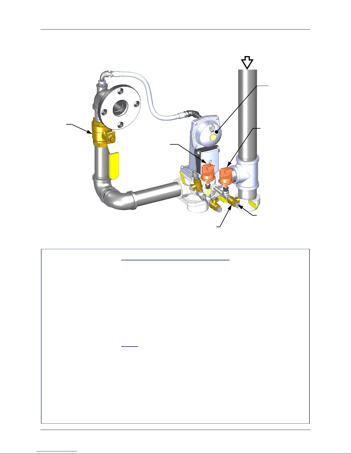
Benchmark 1500 - 2000 Boilers
NATURAL
GAS INLET
LOW GAS
LOW GAS BALL VALVE
CHAPTER 6 – SAFETY DEVICE TESTING
6.2 LOW GAS PRESSURE FAULT TEST
To simulate a low gas pressure fault, refer to Figure 6-1a and perform the following steps:
SSOV
MANUAL
SHUT-OFF
VALVE
HIGH GAS
PRESSURE
SWITCH
PRESSURE
SWITCH
1/4” NPT PLUG
And Ball Valve (install
manometer here for LOW
GAS PRESSURE FAULT
TEST
Figure 6-1a: BMK 1500/2000: Low Gas Pressure Test
Low Gas Pressure Fault Tes t
1. Close the leak detection ball valve located at the low gas pressure switch (see Figure 61a).
2. Remove the 1/4“ plug from the ball valve at the low gas pressure switch shown in the
lower portion of Figure 6-1a.
3. Install a 0 – 16“ W.C. manometer or a W.C. gauge where the 1/4" plug was removed.
4. Slowly open the ball valve near the low gas pressure switch.
5. Place the unit in Manual Mode and adjust the Air/Fuel Valve position (% open) between
25 and 30%.
6. While the unit is firing, slowly close the external manual gas shut-off valve.
7. The unit should shut down and display a GAS PRESSURE fault message at
approximately: 4.4” W.C. for both BMK 1500 and BMK 2000.
8. Fully open the external manual gas shut-off valve and press the CLEAR button on the
Control Box.
9. The fault message should clear and the FAULT indicator should go off. The unit should
restart.
10. Upon test completion, close the ball valve and remove the manometer. Replace the 1/4“
plug removed in step 1.
Page 70 of 184 AERCO International, Inc. • 100 Oritani Dr. • Blauvelt, NY 10913 OMM-0097_0C
Ph.: 800-526-0288 GF-142
Page 71
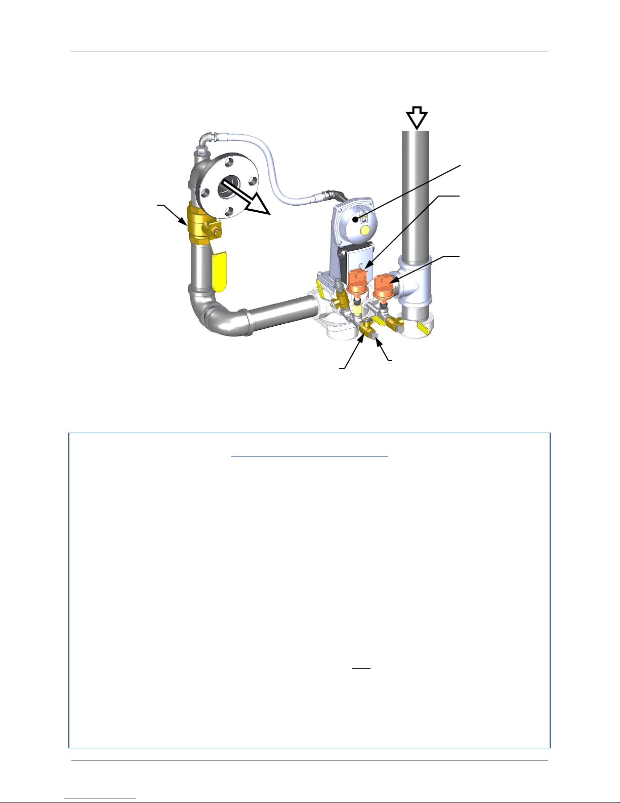
Benchmark 1500 - 2000 Boilers
VALVE
HIGH GAS
SWITCH
NATURAL
GAS INLET
TEST)
CHAPTER 6 – SAFETY DEVICE TESTING
6.3 HIGH GAS PRESSURE TEST
To simulate a high gas pressure fault, refer to Figure 6-1b and perform the following steps:
SSOV
MANUAL
SHUT-OFF
VALVE
TO
AIR/FUEL
PRESSURE
LOW GAS
PRESSURE
SWITCH
HIGH GAS
BALL VALVE
1/4” NPT PLUG and Ball Valve
(install manometer here for
HIGH GAS PRESSURE FAULT
Figure 6-1b: BMK 1500/2000: High Gas Pressure Fault Test
High Gas Pressure Test
1. Close the leak detection ball valve located at the high gas pressure switch (see Figure 61b).
2. Remove the 1/4“ plug from the leak detection ball valve shown in Figure 6-1b.
3. Install a 0 – 16” W.C. manometer (or W.C. gauge) where the 1/4” plug was removed.
4. Slowly open the leak detection ball valve.
5. Start the unit in Manual mode at a valve position (firing rate) between 25 and 30%.
6. With the unit running, monitor the gas pressure on the manometer inst alled in step 2 and
record the gas pressure reading.
7. Slowly increase the gas pressure using the adjustment screw on the SSOV (see Figure
4-3).
8. The unit should shut down and display a HIGH GAS PRESSURE fault message when
the gas pressure exceeds 4.7” W.C. for both BMK 1500 and BMK 2000. The FAULT
indicator should also start flashing.
9. Reduce the gas pressure back to the value recorded in step 5. This pressure should be
within the range of 3.6” ± 0.2” W.C. for BMK 1500 and 3.9” ± 0.2” W.C. for BMK 2000.
10. Press the CLEAR button on the Control Box to clear the fault.
11. The fault message should clear and the FAULT indicator should go off. The unit should
restart.
12. Upon test completion, close the ball valve and remove the manometer. Replace the 1/4“
plug removed in step 1.
OMM-0097_0C AERCO International, Inc. • 100 Oritani Dr. • Blauvelt, NY 10913 Page 71 of 184
GF-142 Ph.: 800-526-0288
Page 72

Benchmark 1500 - 2000 Boilers
CHAPTER 6 – SAFETY DEVICE TESTING
6.4 LOW WATER LEVEL FAULT TEST
To simulate a low water level fault, proceed as follows:
Low Water Level Fault
1. Set the ON/OFF sw itch to the OFF position
2. Close the water shut-off valves in the supply and return piping to the unit.
3. Slowly open the drain valve on the rear of the unit. If necessary the unit’s relief valve
may be opened to aid in draining.
4. Continue draining the unit until a LOW WATER LEVEL fault message is displayed and
the FAULT indicator flashes.
5. Place the unit in the Manual Mode and raise the valve position above 30%.
6. Set the ON/OFF switch to t he ON posit ion. The READY light should remain off and the
unit should not start. If the unit does start, shut the unit off immediately and refer fault to
qualified service personnel.
7. Close the drain and pressure relief valve used in draining the unit.
8. Open the water shut-off valve in the return piping to the unit.
9. Open the water supply shut-off valve to the unit to refill.
10. After the shell is full, press the LOW WATER LEVEL RESET button to reset the low
water cutoff.
11. Press the CLEAR button to reset the FAULT LED and clear the displayed error
message.
12. Set the ON/OFF switch to the ON position. The unit is now ready for operation.
Page 72 of 184 AERCO International, Inc. • 100 Oritani Dr. • Blauvelt, NY 10913 OMM-0097_0C
Ph.: 800-526-0288 GF-142
Page 73
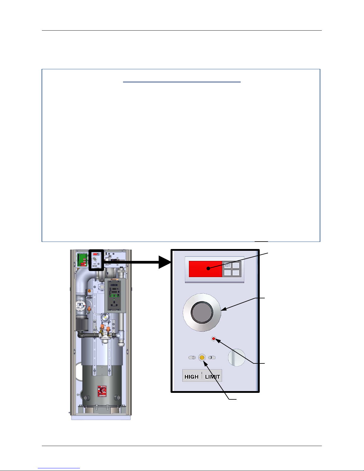
Benchmark 1500 - 2000 Boilers
MANUAL
BUTTON
OVER
CONTROLLER
CHAPTER 6 – SAFETY DEVICE TESTING
6.5 WATER TEMPERATURE FAULT TEST
A high water temperature fault is simulated by adjusting the automatic over-temperature switch.
This switch is accessible from the front of the unit as shown in Figure 6-2.
Water Temperature Fault Test
1. Start the unit in the normal operating mode. Allow the unit to stabilize at its setpoint.
2. Lower the adjustable over-temperature switch setting to match the displayed OUTLET
TEMPERATURE.
3. Once the adjustable over-temperature switch setting is approximately at, or just below,
the actual outlet water temperature, the unit should shut down. The FAULT indicator
should start flashing and a HIGH WATER TEMP SW ITCH OPEN fault message should
be displayed. It should not be possible to restart the unit.
4. Reset the adjustable over-temperature switch to its original setting.
5. The unit should start once the adjustable temperature limit switch setting is above the
actual outlet water temperature.
6. Once the adjustable over-temperature switch setting is approximately at, or just below,
the actual outlet water temperature, the unit should shut down. The FAULT indicator
should start flashing and a HIGH WATER TEMP SW ITCH OPEN fault message should
be displayed. It should not be possible to restart the unit.
7. Reset the adjustable over-temperature switch to its original setting.
8. The unit should start once the adjustable temperature limit switch setting is above the
actual outlet water temperature.
TEMPERATURE
LIMIT DIGITAL
ADJUSTABLE
TEMPERATURE
LIMIT SWITCH
SWITCH
RESET
MANUAL
TEMPERATURE
LIMIT SWITCH
Figure 6-2: Temperature Limit Switch Location
OMM-0097_0C AERCO International, Inc. • 100 Oritani Dr. • Blauvelt, NY 10913 Page 73 of 184
GF-142 Ph.: 800-526-0288
Page 74

Benchmark 1500 - 2000 Boilers
CHAPTER 6 – SAFETY DEVICE TESTING
6.6 INTERLOCK TESTS
The unit is equipped with two interlock circuits called the Remote Interlock and Delayed
Interlock. Terminal connections for these circuits are located in the I/O Box (Figure 2-13) and
are labeled REMOTE INTL’K IN and DELAYED INTL’K IN. These circuits can shut down the
unit in the event that an interlock is opened. These interlocks are shipped from the factory
jumpered (closed). However, each of these interlocks may be utilized in the f ield as a remote
stop and start, an emergency cut-off, or to prove that a device such as a pump, gas booster, or
louver is operational.
6.6.1 Remote Interlock Test
Remote Interlock Test
1. Remove the cover from the I/O Box and locate the REMOTE INTL’K IN terminals.
2. Start the unit in the Manual Mode and set the valve position between 25% and 30%.
3. If there is a jumper across the REMOTE INTL’K IN terminals, remove one side of the
jumper. If the interlock is being controlled by an external device, either open the interlock
via the external device or disconnect one of the wires leading to the external device.
4. The unit should shut down and display INTERLOCK OPEN.
5. Once the interlock connection is reconnected, the INTERLOCK OPEN message should
automatically clear and the unit should restart.
6.6.2 Delayed Interlock Test
Delayed Interlock Test
1. Remove the cover from the I/O Box and locate the DELAYED INTL’K IN terminals.
2. Start the unit in the Manual Mode at a valve position between 25% and 30%.
3. If there is a jumper across the DELAYED INTL’K IN terminals, remove one side of the
jumper. If the interlock is connected to a proving switch of an external device, disconnect
one of the wires leading to the proving switch.
4. The unit should shut down and display a DELAYED I NTERLOCK OPEN fault m essage.
The FAULT LED should be flashing.
5. Reconnect the wire or jumper removed in step 3 to restore the interlock.
6. Press the CLEAR button to reset the fault
7. The unit should start.
Page 74 of 184 AERCO International, Inc. • 100 Oritani Dr. • Blauvelt, NY 10913 OMM-0097_0C
Ph.: 800-526-0288 GF-142
Page 75

Benchmark 1500 - 2000 Boilers
CHAPTER 6 – SAFETY DEVICE TESTING
6.7 FLAME FAULT TESTS
Flame faults can occur during ignition or while the unit is already running. To simulate each of
these fault conditions, proceed as follows:
Flame Fault Tests
1. Set the ON/OFF sw itch to the OFF position.
2. Place the unit in the Manual Mode and set the valve position between 25% and 30%.
3. Close the manual gas shutoff valve located between the Safety Shut-Off Valve (SSOV)
and the Air/Fuel Valve (see Figure 6-3).
4. Set the ON/OFF switch to the ON position to start the unit.
5. The unit should purge and light the Pilot Flame, then it should shut down after reaching
the main burner ignition cycle and display FLAME LOSS DURING IGN.
6. Open the valve previously closed in step 3 and press the CLEAR button.
7. Restart the unit and allow it to prove flame.
8. Once flame is proven, close the manual gas valve located between the SSOV (Figure 6-
3) and the Air/Fuel Valve.
9. The unit should shut down and Lockout, flashing FLDR in the display.
10. Open the valve previously closed in step 8.
11. Press the CLEAR button. The unit should restart and fire.
OMM-0097_0C AERCO International, Inc. • 100 Oritani Dr. • Blauvelt, NY 10913 Page 75 of 184
GF-142 Ph.: 800-526-0288
Page 76
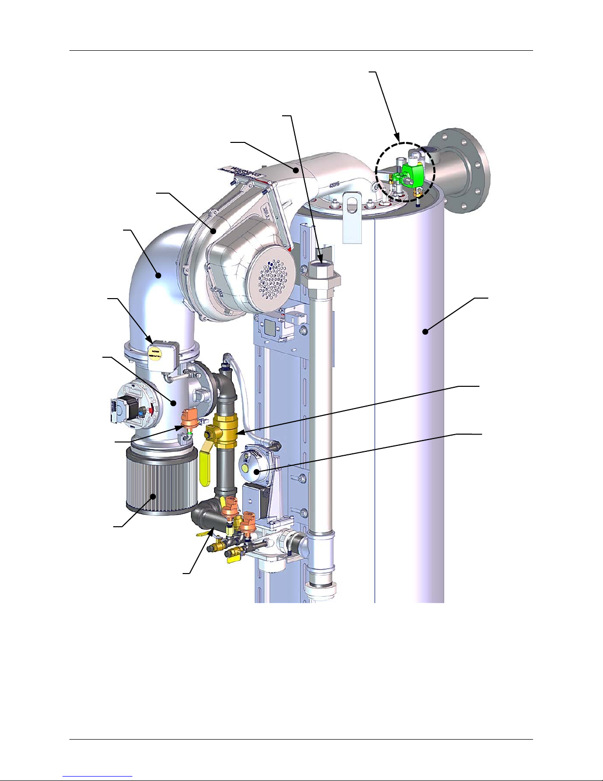
IGNITER/INJECTOR
ASSEMBLY
BLOWER
PLENUM
GAS
INLET
BLOWER
A/F VAL VE
PLENUM
Benchmark 1500 - 2000 Boilers
CHAPTER 6 – SAFETY DEVICE TESTING
BLOWER
PROOF
SWITCH
AIR/FUEL
VALVE
BLOCKED
INLET
SWITCH
AIR
FILTER
HEAT
EXCHANGER
MANUAL
SHUT-OFF
VALVE
SSOV
GAS
TRAIN
Figure 6-3: Bare Boiler – Partial View (BMK 1500/2000)
Page 76 of 184 AERCO International, Inc. • 100 Oritani Dr. • Blauvelt, NY 10913 OMM-0097_0C
Ph.: 800-526-0288 GF-142
Page 77

Benchmark 1500 - 2000 Boilers
CHAPTER 6 – SAFETY DEVICE TESTING
6.8 AIR FLOW FAULT TESTS
These tests check the operation of the Blower Proof Switch and Block ed Inlet Switch shown in
Figure 6-3.
Air Flow Fault Tests
1. Disable the blower output drive voltage as follows:
(a) Press the MENU key until CONFIGURATION MENU is displayed.
(b) Press the ▲ arrow key until the ANALOG OUTPUT function is displayed, then
press the CHANGE key.
(c) Press the ▼ arrow key until OFF is displayed, then press the ENTER key.
2. Start the unit in the Manual Mode at a valve position between 25% and 30%.
3. The unit should shut down and lockout, showing AIRFLOW FAULT DURING PURGE in
the display.
4. The unit should perform one IGNITION RETRY cycle and then shut down, since the
blower is disabled. The unit will then display AIRFLOW FAULT DURING PURGE.
5. Re-enable the blower output drive voltage by performing the following steps:
(a) Press the MENU key until CONFIGUR-ATION MENU is displayed.
(b) Press the ▲ arrow key until the ANALOG OUTPUT function is displayed, then
press the CHANGE key.
(c) Press the ▲ arrow key until VALVE POSITION 0-10V is displayed, then press the
ENTER key.
6. Once the unit has proved flame, turn off the blower again by going to the Configuration
Menu, Analog Output menu item and select OFF.
7. The Blower Proof Switch will open and the blower should stop. The unit should shut
down and display AIRFLOW FAULT DURING RUN.
8. Go to the Configuration Menu, Analog Output item and select VALVE POSITION 0-10v.
9. Press the CLEAR button. The unit should restart.
10. Next, check the operation of the Blocked Inlet Switch located on the air inlet side of the
Air/Fuel Valve (Figure 6-3).
11. Ensure that the sheet metal panels are securely installed on the boiler and the unit is
running.
12. At the rear of the unit, partially block the air inlet (Figure 6-4) with a plywood sheet or
metal plate.
13. The unit should shut down and again display AIRFLOW FAULT DURING RUN.
14. Unblock the air inlet and press the CLEAR button. The unit should restart.
OMM-0097_0C AERCO International, Inc. • 100 Oritani Dr. • Blauvelt, NY 10913 Page 77 of 184
GF-142 Ph.: 800-526-0288
Page 78
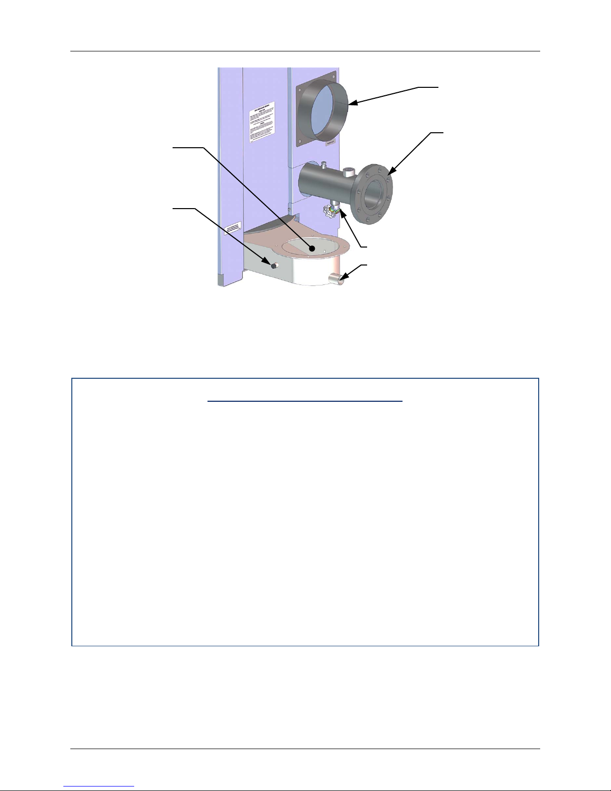
Benchmark 1500 - 2000 Boilers
AIR INLET
PRIMARY
WATER INLET
ANALYZER
PORT
EXHAST
MANIFOLD
CHAPTER 6 – SAFETY DEVICE TESTING
DR AIN VALV E
CONDENSATE DRAIN
Figure 6-4: Boiler Rear View Showing Air Inlet Location
6.9 SSOV PROOF OF CLOSURE SWITCH
The SSOV shown in Figure 6-1 contains the proof of closure switch. The proof of closure switch
circuit is checked as follows:
SSOV Proof of Closure Switch
1. Set the unit’s ON/OFF switch to the OFF position.
2. Place the unit in Manual Mode and set the valve position between 25% and 30%
3. Refer to Figure 6-1 and locate the SSOV.
4. Remove the cover from the SSOV by loosening the screw shown in Figure 6-5. Lift off the
cover to access the terminal wiring connections.
5. Disconnect wire #148 from the SSOV to “open” the proof of closure switch circuit.
6. The unit should fault and display SSOV SWITCH OPEN.
7. Replace wire #148 and press the CLEAR button.
8. Set the ON/OFF switch to the ON position to start the unit.
9. Remove the wire again when the unit reaches the purge cycle and PURGING is
displayed.
10. The unit should shut down and display SSOV FAULT DURING PURGE.
11. Replace the wire on the SSOV and press the CLEAR button. The unit should restart.
Page 78 of 184 AERCO International, Inc. • 100 Oritani Dr. • Blauvelt, NY 10913 OMM-0097_0C
Ph.: 800-526-0288 GF-142
Page 79
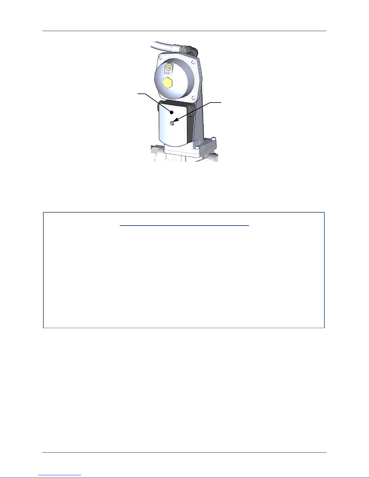
Benchmark 1500 - 2000 Boilers
SSOV
ACTUATOR
CHAPTER 6 – SAFETY DEVICE TESTING
ACTUATOR
COVER
Figure 6-5: SSOV Actuator Cover Location
6.10 PURGE SWITCH OPEN DURING PURGE
The Purge Switch (and Ignition Switch) is located on the Air/Fuel Va lve. To check the switch,
proceed as follows:
COVER
SCREW
Purge Switch Open During Purge
1. Set the unit’s ON/OFF switch to the OFF position. Place the unit in manual mode and
set the valve position between 25% and 30%.
2. Remove the Air/Fuel Valve cover by rotating the cover counterclockwise to unlock it
(see Figure 6-6).
3. Remove one of the two wires (#171 or #172) from the Purge Switch (Figure 6-6).
4. Initiate a unit start sequence.
5. The unit should begin its start sequence, then shut down and display PRG SWITCH
OPEN DURING PURGE.
6. Replace the wire on the Purge Switch and depress the CLEAR button. The unit should
restart.
OMM-0097_0C AERCO International, Inc. • 100 Oritani Dr. • Blauvelt, NY 10913 Page 79 of 184
GF-142 Ph.: 800-526-0288
Page 80
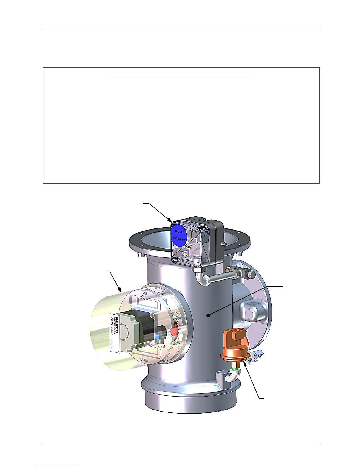
Benchmark 1500 - 2000 Boilers
BLOCKED
BLOWER
CHAPTER 6 – SAFETY DEVICE TESTING
6.11 IGNITION SWITCH OPEN DURING IGNITION
The Ignition Switch (and the Purge Switch) is located on the Air/Fuel Valve. To check the
switch, proceed as follows:
Ignition Switch Open During Ignition
1. Set the unit’s ON/OFF switch to the OFF position.
2. Place the unit in Manual Mode and set the valve position between 25% and 30%.
3. Remove the Air/Fuel Valve cover (Figure 6-6) by rotating the cover counterclockwise to
unlock and lift up to remove.
4. Remove one of the two wires (#169 or #170) from the Ignition Switch (Figure 6-7).
5. Initiate a unit start sequence.
6. The unit should begin its start sequence and then shut down and display IGN SWITCH
OPEN DURING IGNITION.
7. Replace the wire on the Ignition Switch and press the CLEAR button. The unit should
restart.
PROOF
SWITCH
AIR/FUEL VALVE CO V ER
(Rotate Counter-Clock-Wise
to Remove)
Figure 6-6: Air/Fuel Valve Cover Location
AIR/FUEL
VALVE
INLET
SWITCH
Page 80 of 184 AERCO International, Inc. • 100 Oritani Dr. • Blauvelt, NY 10913 OMM-0097_0C
Ph.: 800-526-0288 GF-142
Page 81
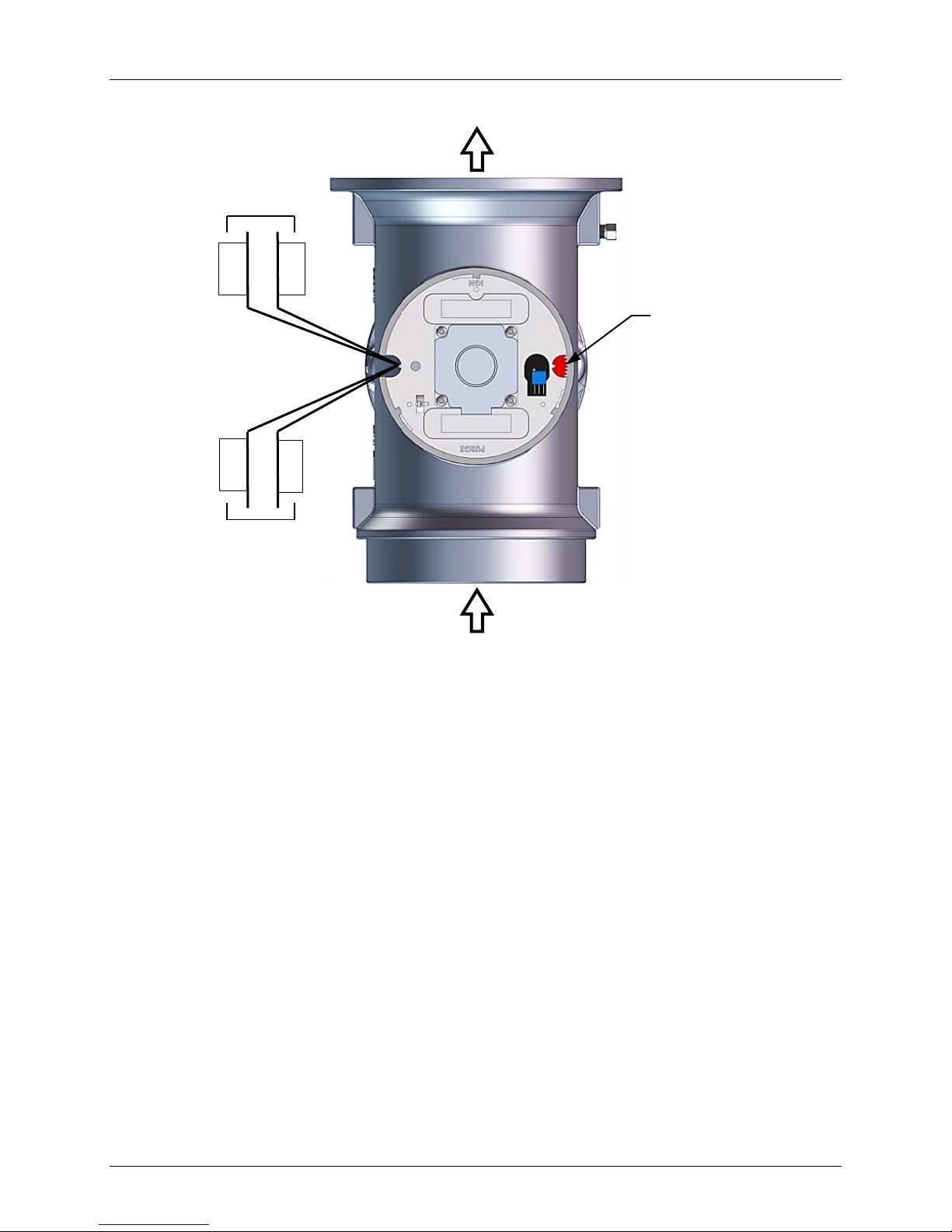
Benchmark 1500 - 2000 Boilers
172
171
170
169
Ignition
Purge
AIR IN
TO BLOWER
VALVE
DIAL
AIR/FUEL VALVE
BREAKOUT
CHAPTER 6 – SAFETY DEVICE TESTING
Position
Switch
POSITION
SWITCH WIRING
Position
Switch
Figure 6-7: Air/Fuel Valve Purge and Ignition Switch Locations
6.12 SAFETY PRESSURE RELIEF VALVE TEST
Test the safety Pressure Relief Valve in accordance with ASME Boiler and Pressure Vessel
Code, Section VI.
OMM-0097_0C AERCO International, Inc. • 100 Oritani Dr. • Blauvelt, NY 10913 Page 81 of 184
GF-142 Ph.: 800-526-0288
Page 82

Benchmark 1500 - 2000 Boilers
CHAPTER 6 – SAFETY DEVICE TESTING
(This Page Is Intentionally Blank)
Page 82 of 184 AERCO International, Inc. • 100 Oritani Dr. • Blauvelt, NY 10913 OMM-0097_0C
Ph.: 800-526-0288 GF-142
Page 83
Benchmark 1500 - 2000 Boilers
Labor
Time
Igniter-Injector
(66013)
Flame Detector
(66020)
O2 Sensor
(61026)
Combustion
Calibration
Testi ng of Safety
Devices
See ASME CSD-1
Chart
7.6
Burner
Inspect
2 hrs.
Condensate
Drain Trap
Inspect, Clean &
Replace Gaskets
Inspect, Clean &
Replace Gaskets
WARNING
CHAPTER 7 – MAINTENANCE
CHAPTER 7. MAINTENANCE
7.1 MAINTENANCE SCHEDULE
The unit requires regular routine maintenance to keep up efficiency and reliability. For best
operation and life of the unit, the following routine maintenance procedures should be performed
in the time periods specified in Table 7-1. For a complete inspection check list see ASME CSD1 chart.
In order to perform the maintenance tasks specified in Table 7-1, the following maintenance kits
are available through your local AERCO Sales Representative:
Annual Maintenance Kit, Part No. 58025-09
24-Month Waterside/Fireside Inspection Kit, Part No. 58025-10 (See NOTE below)
NOTE:
The 24-Month Waterside/Fireside Inspection Kit also includes the items
contained in the Annual Maintenance Kit (58025-09). Therefore, only Kit
Part No. 58025-10 is required when performing the waterside/fireside
inspections. Refer to Appendix L for recommended spare
TO AVOID PERSONAL INJURY, PRI OR TO SERVICING ENSURE T HAT
THE FOLLOWING GUIDELINES ARE STRICTLY OBSERVED:
• DISCONNECT THE AC SUPPLY BY TURNING OFF THE SERVICE
SWITCH AND AC SUPPLY CIRCUIT BRE AKER.
• SHUT OFF THE G AS SUPPLY AT THE MANUAL SHUT-OFF VALVE
PROVIDED WITH THE UNIT
• ALLOW THE UNIT TO COOL TO A SAFE WATER TEMPERATURE
TO PREVENT BURNING OR SCALDING
Table 7-1: Maintenance Schedule
Section Item 6 Mos. 12 Mos. 24 Mos.
7.2
7.3
7.4
4.3
*Inspect Inspect Replace 15 m ins.
*Inspect Inspect Replace 15 m ins.
*Inspect Inspect 15 mins.
*Check Check 1 hr.
7.5
7.7
7.8
* Only performed after initial 6 month period after initial startup.
OMM-0097_0C AERCO International, Inc. • 100 Oritani Dr. • Blauvelt, NY 10913 Page 83 of 184
GF-142 Ph.: 800-526-0288
Air Filter (59138) Clean Replace 15 mins.
*Inspect
45 mins.
30 mins.
Page 84
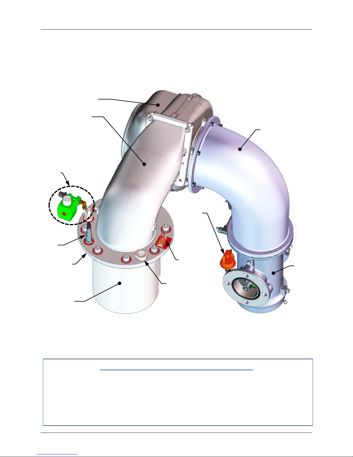
Benchmark 1500 - 2000 Boilers
IGNITOR-
FLAME
DETECTOR
BURNER
PLENUM
FLAME
AIR/FUEL
VALVE
BLOWER
A/F VAL VE
PLENUM
CHAPTER 7 – MAINTENANCE
7.2 IGNITER-INJECTOR
The igniter-injector (part no. 66026) is located on the burner plate at the top of the boiler. In
addition to providing the ignition spark required to light the burner, the igniter-injector also
contains a gas injector tube which connects to the staged ignition assembly. Figure 7-1 shows
the complete burner assembly removed from the boiler and indicates the location of the igniterinjector flame detector and other related components.
BLOWER
BLOWER
PLENUM
INJECTOR
ASSEMBLY
O2 SENSOR
FLANGE/
BURNER
TOP PLATE
The igniter-injector may be hot, therefore, care should be exercised to avoid burns. It is easier to
remove the igniter-injector from the unit after the unit has cooled to room temperature. To
inspect/replace the Igniter:
1. Set the ON/OFF switch on the control panel, to the OFF position. Disconnect AC power
PROOF
SWITCH
OBSERVATION
PORT
Figure 7-1: Benchmark 1500/2000 Burner Assembl y (Rem oved f ro m Boil er)
Igniter-Injector Maint enance Procedures
from the unit
2. Remove the top shroud from the unit by grasping the top handle and lifting straight up.
This will disengage the shroud from the four (4) pins in the side panels.
3. Disconnect the cable from the igniter-injector (Figure 7-1).
Page 84 of 184 AERCO International, Inc. • 100 Oritani Dr. • Blauvelt, NY 10913 OMM-0097_0C
Ph.: 800-526-0288 GF-142
Page 85
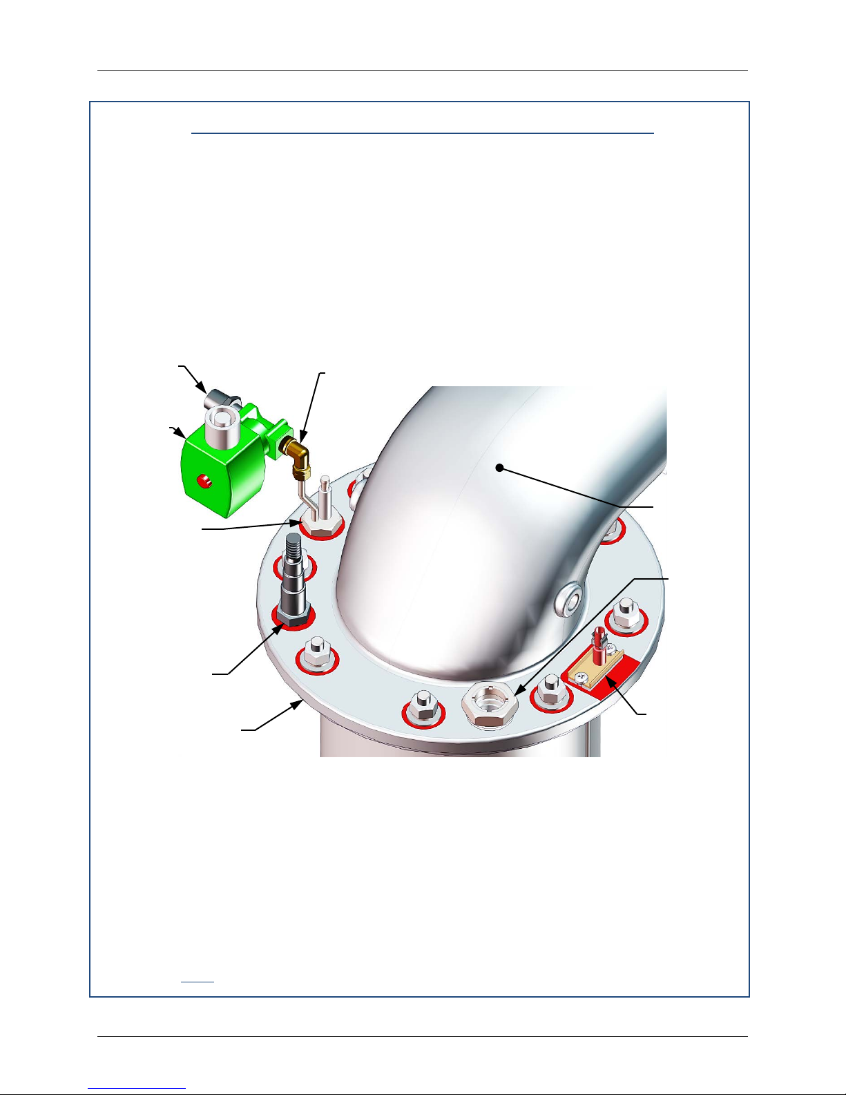
Benchmark 1500 - 2000 Boilers
STAGED
FLAME
FLAME
INJECTOR-
O2 SENSOR
FLEX GAS
COMPRESSION FITTING & ELBOW
BLOWER
PLENUM
CHAPTER 7 – MAINTENANCE
Igniter-Injector Maintenance Procedures – Continued
4. Refer to the partial exploded view in Figure 7-2. Using a 7/16” open-end wrench,
disconnect the compression nut securing the gas injector tube of the igniter-injector to the
elbow of the staged ignition assembly. Disconnect the staged ignition assem bly from the
igniter-injector.
5. Next, loosen and remove the igniter-injector from the burner plate using a 1" open-end
wrench.
6. Check the igniter-injector for evidence of erosion or carbon build-up. If there is evidence
of substantial erosion or carbon build-up, the ig niter-injector should be replaced. If carbon
build-up is present, clean the component using f ine emery cloth. Repeated carbon buildup is an indication that the combustion settings of the unit should be checked. Refer to
Chapter 4 for combustion calibration procedures.
HOSE
NIPPLE
IGNITION
SOLENOID
IGNITOR
ASSY WITH
INDEXING
(CLOCKING)
WASHERS
(0-3 as
needed)
& WASHER
BURNER PLATE
FLANGE
OBSERVATION
PORT
DETECTOR &
GASKET
Figure 7-2: Igniter-Injector & Flame Detector Mounting Details
7. Next, loosen and remove the igniter-injector from the burner plate using a 1" open-end
wrench.
8. Check the igniter-injector for evidence of erosion or carbon build-up. If there is evidence
of substantial erosion or carbon build-up, the ig niter-injector should be replaced. If carbon
build-up is present, clean the component using f ine emery cloth. Repeated carbon buildup is an indication that the combustion settings of the unit should be checked. Refer to
Chapter 4 for combustion calibration procedures.
9. Prior to reinstalling the igniter-injector, a high temperature, conductive, anti-seize com-
pound must be applied to the threads.
OMM-0097_0C AERCO International, Inc. • 100 Oritani Dr. • Blauvelt, NY 10913 Page 85 of 184
GF-142 Ph.: 800-526-0288
Page 86
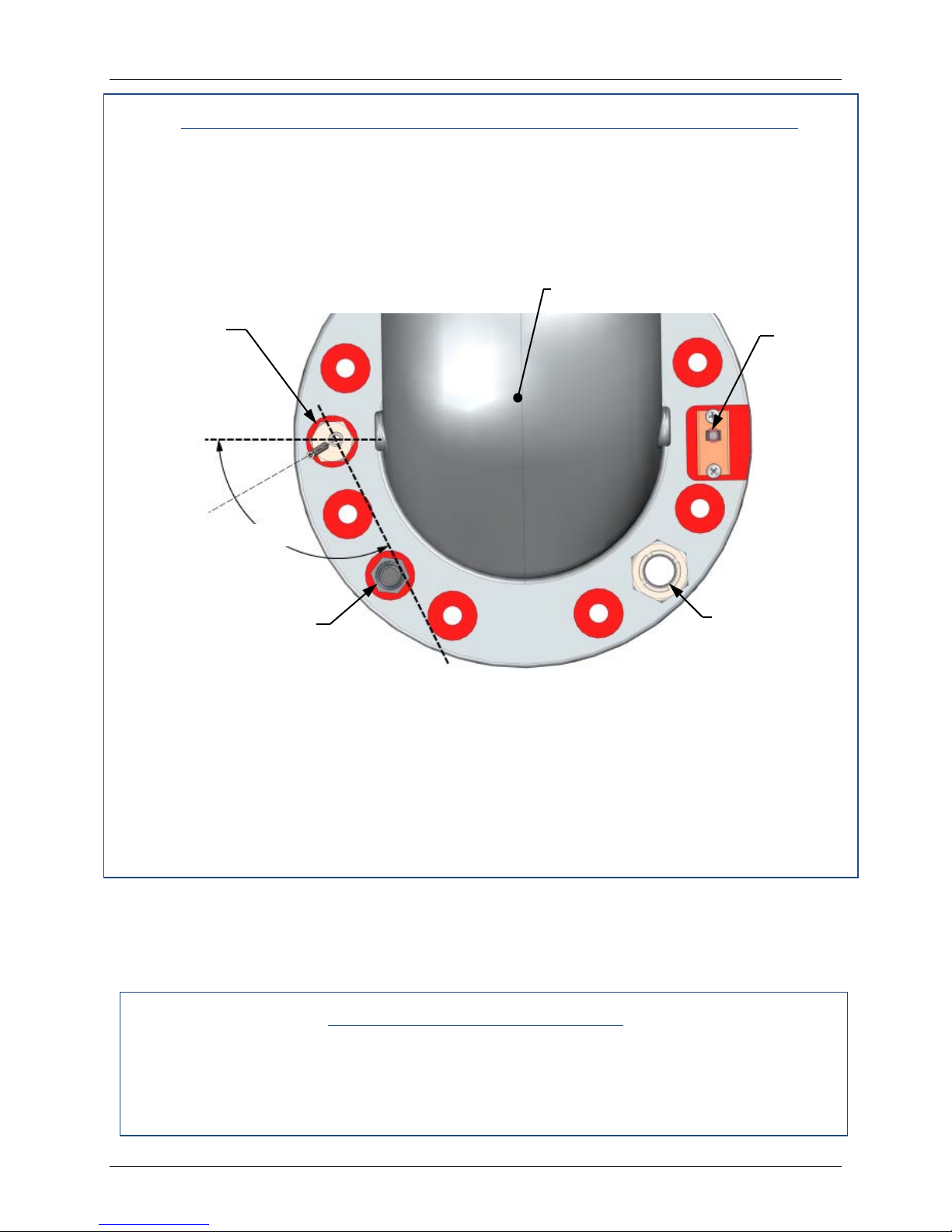
Benchmark 1500 - 2000 Boilers
O2 SENSOR
BLOWER PLENUM
IGNITER-
FLAME
ANGLE OF
120°
FLAME
CHAPTER 7 – MAINTENANCE
IGNITER-INJECTOR MAINTENANCE PROCEDURES – Continued
NOTE
If a replacement igniter-injector (part no. 66026) is being installed,
a compression nut containing a built-in ferrule will be included with
the replacement part. If needed, 3 indexing washers are also
included These washers may be needed to properly position the
gas injector tube of the igniter-injector within the 120° angle range
shown in Figure 7-3.
INJECTOR
GAS INJECTOR
TUBE
OBSERVATION
PORT
ROD
Figure 7-3: Igniter-Injector Orientation (Viewed Looking Down from Above)
10. Reinstall the igniter-injector in the burner plate. Torque to 170 - 180 in-lb s. DO NOT over
tighten.
11. Connect the staged ignition assembly to the gas injector tube of the igniter-injector by
securing the compression nut to the elbow of the staged ignition assembly.
12. Reconnect the igniter-injector cable.
13. Reinstall the shroud on the unit.
7.3 FLAME DETECTOR
The flame detector (part no. 66020) is located on the burner plate at the top of the unit (see
Figures 7-1 and 7-2). The flame detector may be hot. Allow the unit to cool sufficiently before
removing the flame detector. Inspect or replace the flame detector as follows:
1. Set the contr ol panel ON/OFF switch to the OFF position. Disconnect AC power from the
unit.
2. Remove the top shroud from the unit by grasping the top handle and lifting straight up.
This will disengage the shroud from the four (4) pins in the side panels.
Page 86 of 184 AERCO International, Inc. • 100 Oritani Dr. • Blauvelt, NY 10913 OMM-0097_0C
Ph.: 800-526-0288 GF-142
Flame Detector Maintenance
Page 87

Benchmark 1500 - 2000 Boilers
CHAPTER 7 – MAINTENANCE
Flame Detector Maintenance – Continued
3. Disconnect the flame detector lead wire.
4. Remove the two (2) screws securing the flame detect or to the plate (Figure 7-2). The
flame detector is secured to the burner plate with one #10-32 screw and one #8-32
screw.
5. Remove the flame detector and gasket from the burner plate.
6. Thoroughly inspect the flame detector. If eroded, the detector should be replaced.
Otherwise clean the detector with a fine emery cloth.
7. Reinstall the flame detector and flame detector gasket.
8. Reconnect the flame detector lead wire.
9. Reinstall the shroud on the unit.
7.4 O2 SENSOR
The O2 sensor (part no. 61026) is located on the burner plate at t he top of the unit ( see Figures
7-1 and 7-2). The sensor may be hot. Allow the unit to cool sufficiently before removing or
replacing the O
sensor.
2
O2 Sensor Maintenance Procedures
1. Set the ON/OFF switch on the contr ol panel, to the OFF position. Disconnect AC power
from the unit.
2. Remove the top shroud from the unit by grasping the top handle and lifting straight up.
This will disengage the shroud from the four (4) pins in the side panels.
3. Disconnect the O
sensor lead wire by pushing in on the release tab and pulling apart the
2
connector.
4. Next, loosen and remove the O
sensor and crush washer fr om the burner plate using a
2
15/16" open-end wrench.
5. Thoroughly inspect the O
sensor. If eroded, the sensor should be replaced. Otherwise
2
clean the sensor with a fine emery cloth.
6. Reinstall the O
sensor and crush washer on the burner plate.
2
7. Reconnect the sensor lead wire.
8. Reinstall the shroud on the unit.
7.5 SAFETY DEVICE TESTING
Systematic and thorough tests of the operating and safety devices should be performed to
ensure that they are operating as designed. Certain code requirements, such as ASME CSD-1,
require that these tests be performed on a scheduled basis. Test schedules must conform to
local jurisdictions. The results of the tests should be recorded in a log book. See Chapter 6Safety Device Testing Procedures.
OMM-0097_0C AERCO International, Inc. • 100 Oritani Dr. • Blauvelt, NY 10913 Page 87 of 184
GF-142 Ph.: 800-526-0288
Page 88

Benchmark 1500 - 2000 Boilers
Part No.
Description
81180
89038
Burner Gasket (2 each)
Burner Metal Ring (1 each)
81048
Flame Detector Gasket (1 each)
CHAPTER 7 – MAINTENANCE
7.6 BURNER ASSEMBLY INSPECTION
The burner assembly is located at the top of the unit's heat exchanger. The burner assembly
may be hot. Therefore, allow the unit to cool sufficiently before removing the burner assembly.
NOTE
In order to do this procedure most efficiently with a minimum of
steps, a simple support rig has been designed to hold up the
blower and Air/Fuel Valve assembly while the blower plenum is
removed to allow the burner assembly to be removed for
maintenance. Using this support will relieve the blower’s weight
from bearing down upon the connection to the gas train. This
support rig prevents having to dismantle the entire blower and A/V
Valve assembly f rom the gas train. The support rig is available as
an after-market part.
The following parts will be required for reassembly after burner inspection:
88173
Burner Release Gasket (2 each)
To inspect or replace the burner assembly, proceed as follows:
Burner Assembly Inspection and Maintenance Procedures
1. Set the ON/OFF switch on the control panel, to the OFF position. Disconnect AC power
from the unit and turn off the gas supply.
2. Remove the top shroud from the unit by grasping the top handle and lifting straight up.
This will disengage the shroud from the four (4) pins in the side panels.
3. Disconnect the lead wire from the flame detector installed on the burner plate. See Figure
7-2.
4. Remove the two (2) screws securing the flame detector to the plate. The flame detector is
secured to the burner plate with one (1) #10-32 screw and one (1) #8-32 screw.
5. Remove the flame detector and gasket from the burner plate.
6. Disconnect the cable from the igniter-injector.
7. Using a 7/16” open-end wrench, disconnect the compression nut securing the gas injector
tube of the igniter-injector to the elbow of the staged ignition assembly (see Figure 7-2).
Disconnect the staged ignition assembly from the igniter-injector.
8. Next, loosen and remove the igniter-injector from the burner plate using a 1" open-end
wrench.
9. Retrieve the blower support rig and attach it to the blower and unit as described in the
instructions provided with the rig.
10. Loosen and remove the four 5/16x1-3/4” bolts, washers, and nuts from the burner plenum
where it is attached to the blower (see Figure 7-4a & 7-4b).
Page 88 of 184 AERCO International, Inc. • 100 Oritani Dr. • Blauvelt, NY 10913 OMM-0097_0C
Ph.: 800-526-0288 GF-142
Page 89

Benchmark 1500 - 2000 Boilers
CHAPTER 7 – MAINTENANCE
Burner Assembly Inspection and M aintenance Procedures (Cont.)
11. Remove the eight (8) 3/8-16 nuts, using a 9/16” wrench, attaching the blower plenum to
the burner beneath (see Figure 7-4a & 7-4b).
12. Remove the blower plenum from between the blower and the burner and set aside for
later reassembly. O2 sensor and flame observation port remain assembled to the plenum
flange.
NOTE
The burner assembly is heavy, weighing approximately 65 lbs.
13. Remove the burner by pulling straight up.
14. Remove and replace the burner gasket(s) (see Figure 7-5).
IMPORTANT!
ALL THREE gaskets provided for maintenance MUST be installed
during this procedure, as shown in Figure 7-5, even if there is only
one existing gasket being replaced. Note that the LOWER
RELEASE GASKET has tabs, which the others do not.
NOTE
During reassembly, apply a light coating of high-temperature, antiseize lubricant to the threads of the igniter-injector and grounding
screw. Also, ensure that the igniter-injector is properly positioned
as indicated in Figure 7-3. Torque the igniter-injector to 170 - 180
in-lbs.
15. Beginning with the burner assembly, reinstall all the components in the reverse order that
they were removed. When reinstalling the blower plenum (removed in step 11), tighten
the 3/8-16 nuts using a typical torque pattern (f or example, loosely tighten one nut, then
loosely tighten a second nut on the opposite side, a third at 90 deg rees to the first two,
and a fourth opposite the third, and then repeat this pattern with the remaining four nuts.
Repeat the entire pattern a second time to partially tighten all eight nuts, and then repeat
a third time until all eight nuts are fully torqued to 22 ft. lbs).
16. Ensure that the igniter-injector and flame detector cutouts in the burner plate are properly
aligned with the heat exchanger top flange.
OMM-0097_0C AERCO International, Inc. • 100 Oritani Dr. • Blauvelt, NY 10913 Page 89 of 184
GF-142 Ph.: 800-526-0288
Page 90
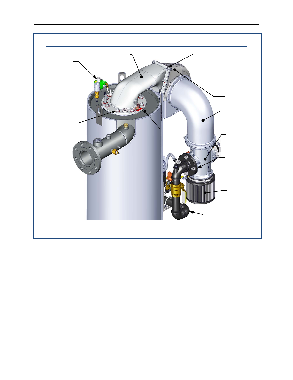
Benchmark 1500 - 2000 Boilers
5/16” x 1-3/4”
(4 each)
BLOWER PLENUM
GAS TRAIN
A/F VAL VE
BLOWER
3/8”-16
(8 each)
AIR/FUEL
IGNITER-
1/2” NUTS
CHAPTER 7 – MAINTENANCE
Burner Assembly Inspection and Maintenance Procedure (Cont.)
BOLTS, 5/16”
INJECTOR
ASSEMBLY
WASHERS &
NYLOCK NUTS
PLENUM
HEX NUTS
Figure 7-4a: Burner Assembly Mounting Details
BURNER
PLATE
VALVE
FILTER
& BOLTS
(4 each)
AIR
FILTER
Page 90 of 184 AERCO International, Inc. • 100 Oritani Dr. • Blauvelt, NY 10913 OMM-0097_0C
Ph.: 800-526-0288 GF-142
Page 91
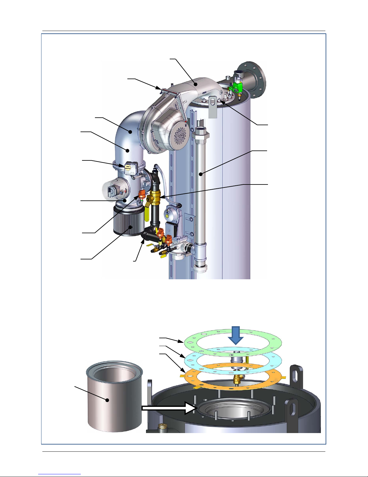
Benchmark 1500 - 2000 Boilers
3/8”-16
(8 each)
A/F
AIR/FUEL
GAS
TRAIN
BLOWER
GAS INLET
PIPE
BLOCKED
BLOWER
BLOWER
MANUAL
BARE
is only one existing gasket being replaced.
NOTE
four tabs around its periphery.
CHAPTER 7 – MAINTENANCE
Burner Assembly Inspection and Maintenance Procedure – Continued
PLENUM
5/16” x 1-3/4” BOLTS,
5/16” WASHERS &
NYLOCK NUTS
(4 each)
HEX NUTS
VALVE
PLENUM
INLET
SWITCH
VALVE
PROOF
SWITCH
AIR
FILTER
Figure 7-4b: Burner Assembly Mounting Details
The LOWER RELEASE
GASKET (P/N 81185) features
81173 – UPPER RELEASE GASKET
81180 – MIDDLE BURNER GASKET
81185 – LOWER RELEASE GASKET
SHUT-OFF
VALVE
Use ALL THREE gaskets provided, even if there
IMPORTANT!
BURNER
INSTALLED
IN HEAT
EXCHANGER
ASSY.
Figure 7-5: Bare Burner and Replacement Gaskets Location
OMM-0097_0C AERCO International, Inc. • 100 Oritani Dr. • Blauvelt, NY 10913 Page 91 of 184
GF-142 Ph.: 800-526-0288
Page 92
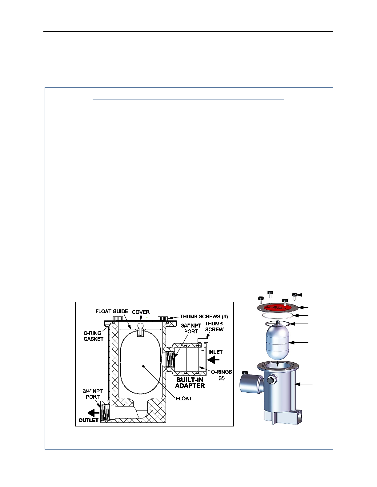
Benchmark 1500 - 2000 Boilers
THUMB
SCREWS
COVER
GASKET
FLOAT
FLOAT
CONDENSATE
(P/N 24060)
CHAPTER 7 – MAINTENANCE
7.7 CONDENSATE DRAIN TRAP
Benchmark boilers contains a condensate trap as shown in Chapter 2, Figure 2-5. The trap is
located external to the unit and attached to the drain pipe from the exhaust manifold. This trap
should be inspected and cleaned in accordance with the maintenanc e schedule shown in Table
7-1 to ensure proper operation. To inspect and clean the trap, proceed as follows:
Condensate Drain Trap Maint enance Procedure
1. Disconnect the external condensate trap by loosening the union pipe connection between
the trap and the exhaust manifold drain pipe.
2. Remove the connections on the inlet and outlet sides of the condensate trap shown in
Figure 7-6.
3. Loosen the four (4) thumbscrews securing the cover on the condensate trap. Remove the
cover.
4. Remove the float from the condensate trap.
5. Remove the O-ring and orifice gaskets from the trap. AERCO recommends that these
items be replaced annually.
6. Thoroughly clean the trap and float. Also inspect the drain piping for blockage. If the trap
cannot be thoroughly cleaned, replace the trap.
7. After the above items have been inspected and thoroughly cleaned, replace the O-ring
(84017) and orifice gasket (81092) with new parts.
8. Reassemble all piping and hose connections to the condensate trap inlet and outlet.
Reconnect trap to exhaust manifold drain.
NOTE
here are two slightly different types of condensate traps that may
T
be used in your configuration; an older style with a separate inlet
adapter, and a newer style with a built-in adapter (see Figure 11).
Maintenance is the same, except that the newer style does not
need an orifice gasket (Step 6).
GUIDE
Figure 7-6: External Conden sat e Trap: Cu t aw ay and Exploded Views
Page 92 of 184 AERCO International, Inc. • 100 Oritani Dr. • Blauvelt, NY 10913 OMM-0097_0C
Ph.: 800-526-0288 GF-142
TRAP
Page 93
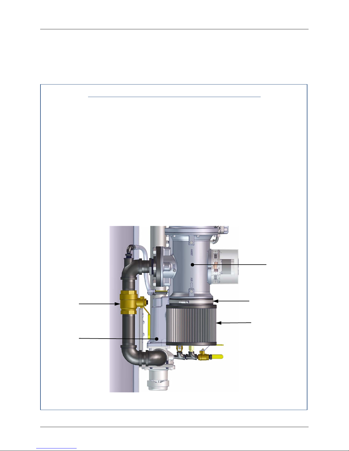
Benchmark 1500 - 2000 Boilers
GAS
TRAIN
AIR
MANUAL
VALVE
CHAPTER 7 – MAINTENANCE
7.8 AIR FILTER CLEANING & REPLACEMENT
The Benchmark boiler is equipped with an air filter (part no. 88014) which should be cleaned
and re-oiled every 12 months and replaced every 24 months. The air filter is located at the inlet
of the air fuel valve at the top of the boiler as shown in Figure 7-7.
To inspect/replace the air filter, proceed as follows:
Air Filter Cleaning & Replacement P rocedures
1. Set the ON/OFF switch on the control panel, to the OFF position. Disconnect AC power
from the unit.
2. Remove the top shroud from the unit by grasping the top handle and lifting straight up.
This will disengage the shroud from the four (4) pins in the side panels.
3. Refer to Figure 7-7 and locate the air filter attached to the air/fuel valve inlet.
4. Using a flat-t ip screwdriver or 5/16” nut driver, loosen the clamp securing the filter to the
inlet flange of the air/fuel valve. Remove the filter and clamp.
5. The filter may be cleaned in hot soapy water to remove oil and d irt. The filter should be
thoroughly dried and then sprayed with a light coating of oil, such as WD-40, prior to
reinstallation.
6. Each replacement air filter is equipped with its own clamp. Therefore, simply install t he
replacement air filter on inlet flange of the air fuel valve and tighten the clamp with a f lattip screwdriver or 5/16” nut driver.
7. Replace the top shroud on the unit and return boiler to service use.
AIR/FUEL
VALVE
AIR FILTER
SHUT-OFF
HOSE CLAMP
FILTER
OMM-0097_0C AERCO International, Inc. • 100 Oritani Dr. • Blauvelt, NY 10913 Page 93 of 184
GF-142 Ph.: 800-526-0288
Figure 7-7: Air Filter Location
Page 94

Benchmark 1500 - 2000 Boilers
CHAPTER 7 – MAINTENANCE
7.9 SHUTTING THE BOILER DOWN FOR AN EXTENDED P ERIOD OF TIME
If the boiler is to be taken out of s ervice for an extended period of time (one year or more) , the
following instructions must be followed.
Shutting Boiler Down for E xtended Period
1. Set ON/OFF switch on the front panel to the OFF position to shut down the boiler’s
operating controls.
2. Disconnect AC power from the unit.
3. Close the water supply and return valves to isolate boiler.
4. Close external gas supply valve.
5. Open relief valve to vent water pressure.
7.10 PLACING THE BOILER BACK IN SERVICE AFTER A PROLONGED
SHUTDOWN
After a prolonged shutdown (one year or more), the following procedures must be followed:
Placing Boiler in Service A fter Long Shutdown
1. Review installation requirements included in Chapter 2.
2. Inspect all piping and connections to the unit.
3. Inspect exhaust vent and air inlet duct work (if applicable).
4. Perform initial startup per Chapter 4.
5. Perform safety device testing and scheduled maintenance procedures per Chapters 6
and 7 of this manual.
Page 94 of 184 AERCO International, Inc. • 100 Oritani Dr. • Blauvelt, NY 10913 OMM-0097_0C
Ph.: 800-526-0288 GF-142
Page 95

Benchmark 1500 - 2000 Boilers
CHAPTER 8 – TROUBLESH OOTING GUIDE
CHAPTER 8. TROUBLESHOOTING GUIDE
8.1 INTRODUCTION
This troubleshooting guide is intended to aid service/maintenance personnel in isolating the
cause of a fault in a Benchmark 1500 MBH and 2000 MBH boilers. The troubleshooting
procedures contained herein are presented in tabular form on the following pages. These
tables are comprised of three columns labeled: Fault Indication, Probable Cause and Corrective
Action. The numbered items in the Probable Cause and Corrective Action columns correspond
to each other. For example, Probable Cause No. 1 corresponds to Corrective Action No. 1, etc.
NOTE
The front panel of the C-More Control Box contains an RS-232
port which can be interfaced to a laptop computer or other suit able
device. This RS-232 communication feature permits service
personnel to view menu items and data logs which can be useful
in isolating faults. Refer to Chapter 9 of this manual for detailed
RS-232 communication set-up and procedures.
When a fault occurs in the unit, proceed as follows to isolate and correct the fault:
Fault Correction
1. Observe the fault messages displayed in the Control Box display.
2. Refer to the Fault Indication column in Troubleshooting Table 8-1 which follows and
locate the Fault that best describes the existing conditions.
3. Proceed to the Probable Cause column and start with the first item (1) listed for the Fault
Indication.
4. Perform the checks and procedures listed in the Corrective Action column for the first
Probable Cause candidate.
5. Continue checking each additional Probable Cause for the existing fault until the fault is
corrected.
6. Section 8.2 and Table 8-2 contain additional troubleshooting information which may apply
when a no fault message is displayed.
If the fault cannot be corrected using the information provided in the Troubleshooting Tables,
contact your local AERCO Representative.
OMM-0097_0C AERCO International, Inc. • 100 Oritani Dr. • Blauvelt, NY 10913 Page 95 of 184
GF-142 Ph.: 800-526-0288
Page 96

Benchmark 1500 - 2000 Boilers
CHAPTER 8 – TROUBLESH OOTING GUIDE
(This page left intentionally blank)
Page 96 of 184 AERCO International, Inc. • 100 Oritani Dr. • Blauvelt, NY 10913 OMM-0097_0C
Ph.: 800-526-0288 GF-142
Page 97

Benchmark 1500 - 2000 Boilers
CHAPTER 8 – TROUBLESHOOTING GUIDE
OMM-0097_0C AERCO International, Inc. • 100 Oritani Dr. • Blauvelt, NY 10913 Page 97 of 184
GF-142 Ph.: 800-526-0288
TABLE 8-1: BOILER TROUBLESHOOTING
FAULT INDICATION PROBABLE CAUSES CORRECTIVE ACTION
AIRFLOW FAULT
DURING IGNITION
1.
Blower stopped running due to thermal
or current overload.
2. Blocked Blower inlet or inlet air filter.
3. Blockage in Blower Proof switch.
4. Blockage in Blocked Inlet switch.
5. Defective Blower Proof switch.
6. Defective Blocked Inlet switch.
7. Loose temperature to AUX connection in
I/O Box.
8. Defective temperature sensor.
9. Loose wire connection between the 0-
10V signal from I/O box to the Blower
input.
10. Defective I/O Box.
11. Wrong 0-10V output selection on the
control box.
12. Defective Air-Fuel Valve potentiometer.
13. Hard light.
1.
Check combustion blower for signs of excessive heat or high
current drain that may trip thermal or current overload devices.
2. Inspect the inlet to the combustion blower including the air
filter at the air/fuel valve for signs of blockage.
3. Remove the Blower Proof switch and inspect for signs of
blockage, clean or replace as necessary.
4. Remove the Blocked Inlet switch and inspect for signs of
blockage, clean or replace as necessary.
5. Check the continuity of the Blower Proof switch with the
combustion blower running. If there is an erratic resistance
reading or the resistance reading is greater than zero ohms,
replace the switch.
6. Turn off unit and check the continuity of the Blocked Inlet
switch. If there is an erratic resistance reading or the
resistance reading is greater than zero ohms, replace the
switch.
7. Check the actual inlet air temperature and measure voltage at
AUX input in the I/O Box. Verify that the voltage conforms to
the values shown in the tabular listing provided in Appendix C.
8. Refer to CORRECTIVE ACTION 7 and verify that the voltage
conforms to the values shown in Appendix C.
9. Check wire connection from I/O Box 0-10V signal to the
Blower Motor.
10. Measure voltage at the I/O box 0-10V output. A voltage of
10V equates to a 100% open valve position.
11. Check the Analog Out option on the C-More Configuration
Menu. Valve Position 0-10V should be selected.
12. Check Air/Fuel Valve position at 0%, 50% and 100% open
positions. The positions on the VALVE POSITION bargraph
should match the readings on the Air/Fuel Valve dial.
13. Check igniter-injector for soot or erosion of electrode. Check
injector solenoid valve to insure proper open/close operation.
Page 98

Benchmark 1500 - 2000 Boilers
CHAPTER 8 – TROUBLESHOOTING GUIDE
Page 98 of 184 AERCO International, Inc. • 100 Oritani Dr. • Blauvelt, NY 10913 OMM-0097_0C
Ph.: 800-526-0288 GF-142
TABLE 8-1: BOILER TROUBLESHOOTING – Continued
FAULT INDICATION PROBABLE CAUSES CORRECTIVE ACTION
AIRFLOW FAULT
DURING PURGE
1.
Blower not running or running too
slow.
2. Defective Blocked Inlet switch.
3. Blockage in air filter or Blocked
Inlet switch.
4. Blocked blower inlet or inlet
ductwork.
5. No voltage to Blocked Inlet switch
from C-More Control Box.
6. PROBABLE CAUSES from 3 to 12
for AIRFLOW FAULT DURING
IGNITION apply for this fault.
1.
Start the unit. If the blower does not run check the blower solid
state relay for input and output voltage. If the relay is OK, check
the blower.
2. Start the unit. If the blower runs, turn off unit and check the
Blocked Inlet switch for continuity. Replace the switch if
continuity does not exist.
3. Remove the air filter and Blocked Inlet switch and inspect for
signs of blockage. Clean or replace as necessary.
4. Inspect the inlet to the combustion blower including any
ductwork leading up to the combustion blower for signs of
blockage.
5. During the start sequence, verify that 24 VAC is present
between each side of the switch and ground. If 24 VAC is not
present, refer fault to qualified service personnel.
6. See CORRECTIVE ACTIONS from 3 to 12 for AIRFLOW
FAULT DURING IGNITION.
AIRFLOW FAULT
DURING RUN
1.
Blower stopped running due to
thermal or current overload.
2. Blocked Blower inlet or inlet
ductwork.
3. Blockage in air filter or Blocked
Inlet switch.
4. Defective Blocked Inlet switch.
5. Combustion oscillations.
6. Probable causes from 3 to 16 for
AIRFLOW FAULT DURING
IGNITION applies for this fault.
1.
Check combustion blower for signs of excessive heat or high
current draw that may trip thermal or current overload devices.
2. Inspect the inlet to the combustion blower, including any
ductwork leading up to the combustion blower, for signs of
blockage.
3. Remove the air filter and Blocked Inlet switch and inspect for
signs of blockage, clean or replace as necessary.
4. Verify that 24 VAC is present between each side of the switch
and ground. If 24 VAC is not present at both sides, replace
switch.
5. Run unit to full fire. If the unit rumbles or runs rough, perform
combustion calibration.
6. See CORRECTIVE ACTIONS from 3 to 12 for AIRFLOW
FAULT DURING IGNITION.
Page 99

Benchmark 1500 - 2000 Boilers
CHAPTER 8 – TROUBLESHOOTING GUIDE
OMM-0097_0C AERCO International, Inc. • 100 Oritani Dr. • Blauvelt, NY 10913 Page 99 of 184
GF-142 Ph.: 800-526-0288
TABLE 8-1: BOILER TROUBLESHOOTING – Continued
FAULT INDICATION PROBABLE CAUSES CORRECTIVE ACTION
DELAYED
INTERLOCK OPEN
1. Delayed Interlock Jumper not
properly installed or missing.
2. Device proving switch hooked to
interlocks is not closed.
1. Check to insure jumper is properly installed across the delayed
interlock terminals in the I/O Box.
2. If there are 2 external wires on these terminals, check to see if
an end switch for a proving device (such as a pump, louver,
etc.) is tied these interlocks. Ensure that the device and/or its
end switch is functional. A jumper may be temporarily installed
to test the interlock.
DIRECT DRIVE
SIGNAL FAULT
1. Direct drive signal is not present:
--Not yet installed.
--Wrong polarity.
--Signal defective at source.
--Broken or loose wiring.
2. Signal is not isolated (floating).
3. Control Box signal type selection
switches not set for correct signal
type (voltage or current).
1. Check I/O Box to ensure signal is hooked up.
--Hook up if not installed.
--If installed, check polarity.
--Measure signal level.
--Check wiring continuity between source and unit.
2. Check signal at source to ensure it is isolated.
3. Check DIP switch on PMC board to ensure it is set correctly for
the type of signal being sent. Check control signal type set in
Configuration Menu.
FLAME LOSS
DURING IGN
1. Worn Flame D etector.
2. No spark from Spark Igniter.
3. Defective Ignition Transformer.
4. Defective Ignition/Stepper (IGST)
Board.
5. Defective SSOV.
1. Remove and inspect the Flame Detector for signs of wear.
Replace if necessary.
2. Close the internal gas valve in the unit. Install and arc a spark
igniter outside the unit.
3. If there is no spark, check for 120VAC at the primary side to the
ignition transformer during the ignition cycle.
4. If 120VAC is not present, the IGST Board in the Control Box
may be defective. Refer fault to qualified service personnel.
5. While externally arcing the spark igniter, observe the open/close
indicator in the Safety Shut-Off Valve to ensure it is opening. If
the valve does not open, check for 120VAC at the valve input
terminals. If 120VAC is not present, the IGST board in the
Control Box may be defective. Refer fault to qualified service
personnel.
Page 100

Benchmark 1500 - 2000 Boilers
CHAPTER 8 – TROUBLESHOOTING GUIDE
Page 100 of 184 AERCO International, Inc. • 100 Oritani Dr. • Blauvelt, NY 10913 OMM-0097_0C
Ph.: 800-526-0288 GF-142
TABLE 8-1: BOILER TROUBLESHOOTING – Continued
FAULT INDICATION PROBABLE CAUSES CORRECTIVE ACTION
(continued) 6. Carbon or other debris on
Burner.
7. Staged ignition solenoid valve
doesn’t open.
8. Clogged staged ignition piece.
6. Remove View-Port and inspect Burner with Boroscope. If
it is fouled or black with soot, remove the Burner and
inspect for any carbon build-up or debris. Clean and
reinstall.
7. When unit goes to ignition, listen for a clicking sound at
the staged ignition solenoid valve to ensure it is opening.
8. Remove and inspect staged ignition piece for blockage.
FLAME LOSS
DURING RUN
1. Worn Flame D etector or cracked
ceramic.
2. Defective Regulator.
3. Poor combustion calibration.
4. Debris on burner.
5. Blocked condensate drain.
1. Remove and inspect the Flame Detector for signs of wear
or cracked ceramic. Replace if necessary.
2. Check gas pressure readings using a gauge or
manometer into and out of the Air/Fuel Valve to ensure
that the gas pressure into and out of the valve is correct.
3. Check combustion calibration using procedures in
Chapter 4.
4. Remove the burner and inspect for any carbon build-up or
debris. Clean and reinstall.
5. Remove blockage in condensate drain.
HEAT DEMAND
FAILURE
1. The Heat Demand Relays on the
Ignition/Stepper (IGST) board
failed to activate when
commanded.
2. Relay is activated when not in
Demand.
1. Press CLEAR button and restart the unit. If the fault
persists, replace Ignition/Stepper (IGST) Board.
2. Defective relay. Replace IGST Board.
HIGH EXHAUST
TEMPERATURE
1. Poor combustion calibration.
2. Carboned heat exchanger due to
incorrect combustion calibration.
1. Check combustion calibration using procedures in
Chapter 4.
2. If exhaust temperature is greater than 200
o
F, check
combustion calibration. Calibrate or repair as necessary.
 Loading...