

Page 1
ENTERTAINMENT LC ML RIGITFS REb;ERVED. PAT.
OWNER’S MANUAL
PLEASE READ FIRST
BEFORE PLUGGING IN MACHINE
2071 NORTH DIXIE HWY., POMPANO BEACH, FLORIDA 33060
FOR SERVICE PLEASE CALL:
IN USA:
800-808-8860
OUTSIDE USA: 954-781-8080
SALES FAX: 954-781-7900
SERVICE/PARTS FAX: 954-781-3004
Page 2
n
G
n
DONOTTURNGAMEON
HAVEREADTHEFOLLOWING:
FACTORY PRECAUTIONS MUST BE IN PLACE TO PREVENT
ELECTRICAL SHOCK HAZARD TO PLAYERS. ALWAYS REMEMBER
TO DISCONNECT POWER BEFORE ATTEMPTING ANY REPAIRS.
THIS GAME SHOULD BE PLUGGED INTO A 3 WIRE GROUNDED
OUTLET 115 VOLT
FCCPART
15
RULE
UNLESS OTHERWISE SPECIFIED.
THISEQUIPMENTHASBEENTESTEDANDFOUNDTOCOMPLYWITHTHE
OR PART
15
ELECTRICALSPECIFICATIONS
POWER CONSUMPTION....................
LINEVOLTAGE
. . . . . . . . . . . . . . . . . . . . . . . . . . .
115VAC RMS
Hz
COPYRIGHT 01996 BENCHMARK ENTERTAINMENT, LC ALL RIGHTS RESERVED.
THE GAME, TECHNICAL MANUAL, GRAPHIC DESIGNS AND SCHEMATIC DIAGRAMS ARE
PROTECTED BY THE U.S. COPYRIGHT ACT OF 1979. BENCHMARK ENTERTAINMENT
WILL ENFORCE ITS COPYRIGHT AND PATENTS AGAINST INFRINGERS.
Page 3
I. OVERVIEW: IDENTIFYING MAIN COMPONENTS
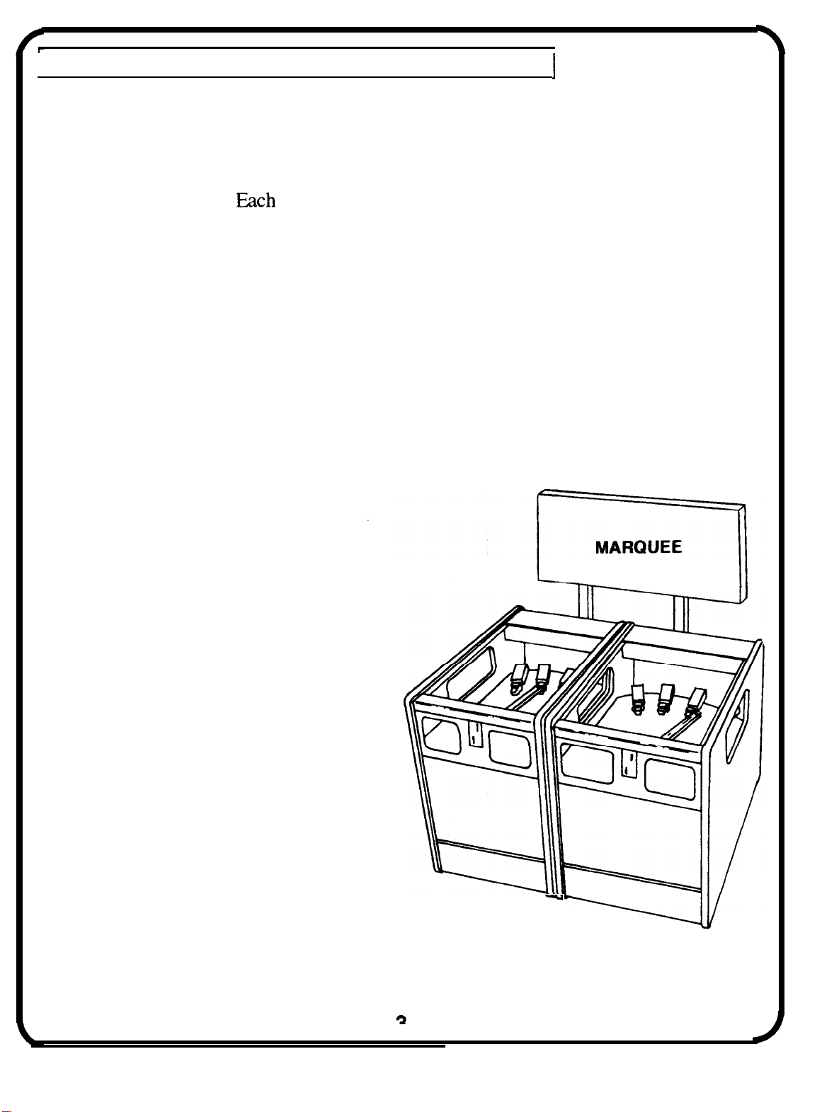
The main components of Big Haul are the Mainstation Cabinet, Slavestation Cabinet, and
the Upright Marquee.
gamestation contains four dump trucks and moving coin
ramp. The marquee contains the speaker assembly, strobe lamp and chase lighting.
Mainstation Cabinet:
The Mainstation Cabinet is the left hand cabinet and contains CPU, power supply, master
reset, and wiring harness to connect the Slavestation Cabinet.
Slavestation Cabinet:
The Slavestation Cabinet is the right hand cabinet and must be connected to the
Mainstation Cabinet in order to function. This gamestation can not play by itself.
Features of the Game:
1. 20 watt adjustable sound system
2. Appealing chase lighting system
3. Single board CPU
4. Two 6000 ticket holders
5. Front and Rear Door Service
6. Fully operator adjustable
entries
MAINSTATION
SLAVESTATION
Page 4
OVERVIEW:
PLAYS
Time the insertion of a coin down the moving coin ramp correctly and hit a truck’s dump
lever. If you miss the dump lever, the token will either land in a truck bed scoring tickets,
or miss completely and fall in the pit, scoring nothing.
A correctly timed token down the coin ramp will hit the truck’s dump lever causing the truck
to-dump its load of tokens into the pit, thus
tickets
c-l__-
The
Ticket Bonus feature will randomly light in front of each truck when all trucks have
reached 15 coins or more. A truck’s bonus lamp will flash if the number of tokens in a truck
is less than 15 coins, or if the dump lever is hit--enticing players to fill up the low trucks.
IMPORTANT!
HOW TO SEED THE TRUCKS ( For First Time Startup Only):
1.
2. Reset Game by holding down Mainstation coin switch for 5 seconds.
12 coins in each truck.
This will credit each truck for 12 coins so ticket payout will be correct on first dump.
All 100 Ticket Bonus lamps will light continuously while switch
is depressed.
The Mainstation will dispense dip switch selected number of tickets.
100 Ticket Bonus lamps will flash in front of each truck.
3. Hold down the Slavestati.on coin switch briefly to setup bonus lamps.
The
will dispense dip switch selected number of tickets.
100 Ticket Bonus lamps will flash in front of each truck.
After a truck dump, the
ticket bonus lamp will flash until 15 coins are in truckbed.
This feature is to entice play on an empty truck.
Page 5
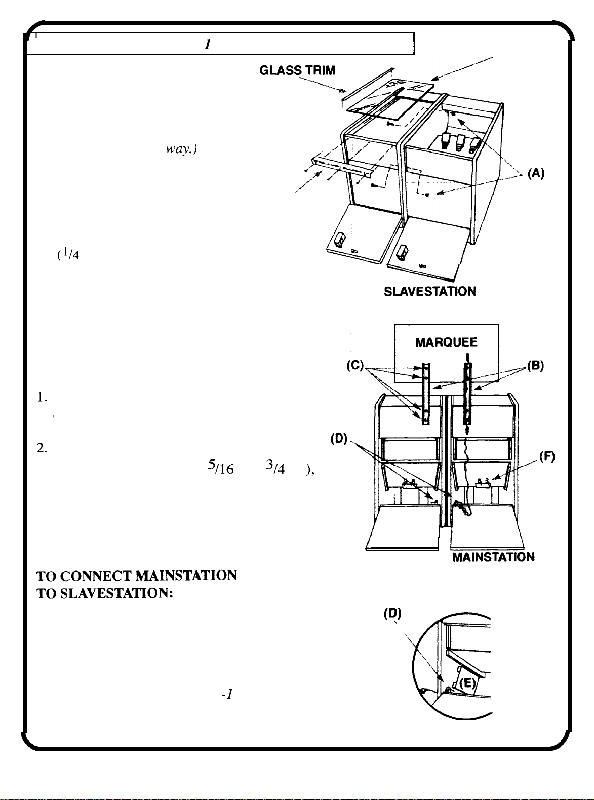
II. ASSEMBLY: STEP
(Note: Both Mainstation
and Slavestation cabinets
disassemble the same
-ASSEMBLE MAIN CABINETS
TOP GLASS
1. Position cabinets as shown.
2. Open front doors.
3. Install hex bolts (A) 2 places
in. x 2 in. long).
TO INSTALL MARQUEE:
Install marquee as shown.
(Note: Marquee supports (B) are bolted
to back of cabinets for shipping.)
Install marquee supports to cabinet first
using four hex bolts (C) (
then mount marquee using remaining bolts
of the same size and tighten.
in. x
SERVICE
ACCESS
TRIM ,
MAINSTATION
in.
SLAVESTATION
1. Open rear doors.
2. Connect harness from mainstation to slavestation
through hole between both cabinets (D).
3. Computer PCB (CPU) (E).
For more details see Page II
3
4. Coin Miss Switch Assy (F). See page IO for details.
5
a
Page 6
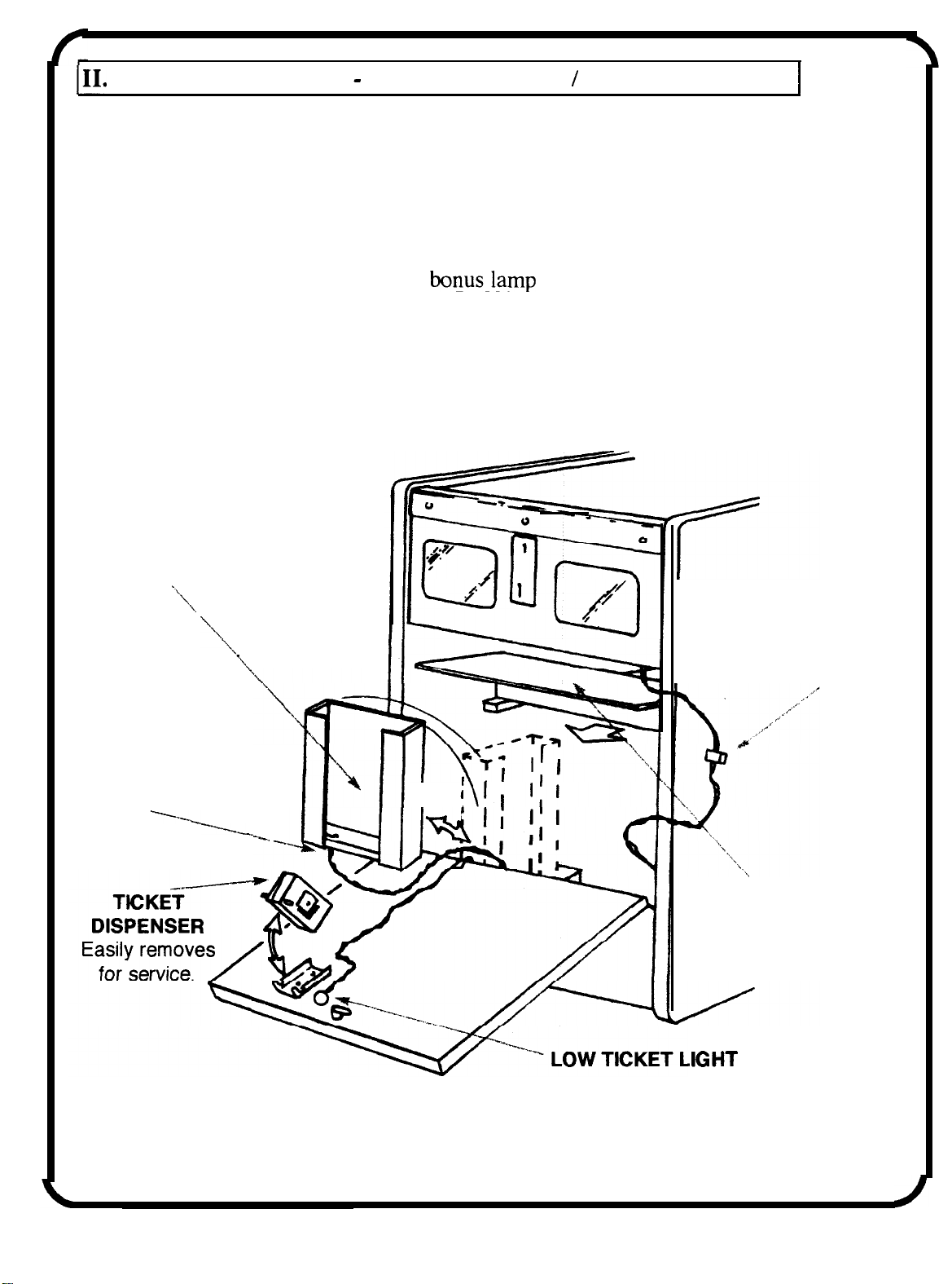
ASSEMBLY: STEP2
1.
While top glass is still off, put 12 coins in each truck bed.
2.
Next, hold down coin switch for 5 seconds.
SEEDING TRUCKS
This will credit each truck for 12 coins so ticket
payout will be correct on first dump.
3.
After a truck dump, the 100 ticket
will
flash until 15 coins are in truckbed.
(This feature is to entice play on an empty truck.)
4.
Next, install tickets as shown.
5.
Adjust coin chutes for your coin size.
TICKET HOLDER
(6000 cap.)
Can be moved as
shown for easy fill.
See next page for details.
LOADING TICKETS
LOW TICKET
SWITCH
.
I
CONNECTOR
PLAYFIELD
6
Page 7
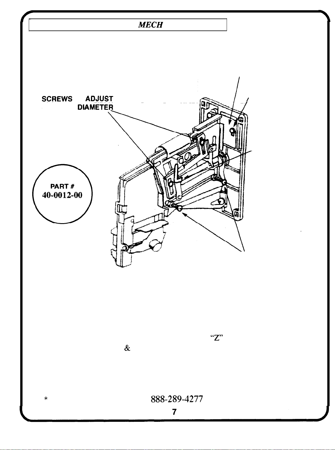
II. ASSEMBLY:
COIN
ADJUSTMENTS
COIN MECH CAN BE ADJUSTED FOR ALL TYPE
COINS USING ADJUSTMENTS BELOW.
ENTRY RESTRICTOR
FOR COIN
RESTRICTOR SCREW
, INCLINE HOOK
-SCREWS
FOR COIN WIDTH
TO ADJUST
MECH MUST BE MOUNTED UPRIGHT AND VERTICAL
WHILE ADJUSTMENT IS BEING MADE.
ADJUSTMENT:
1.
Loosen “restrictor screw” and move entry restrictor up or down to just allow coin to pass.
2. Loosen “screws to adjust for coin diameter”.
to just allow coin to pass
3.
loosen locknuts on “screws to adjust for coin width” and turn these screws in or out
re-tighten.
Move
shaped bracket up or down
to just allow the coin to pass the incline hook. Then, re-tighten locknuts (coin will
get caught on incline hook if width screws are not adjusted properly).
CALL HAPP CONTROLS AT
FOR PARTS AND SERVICE.
Page 8
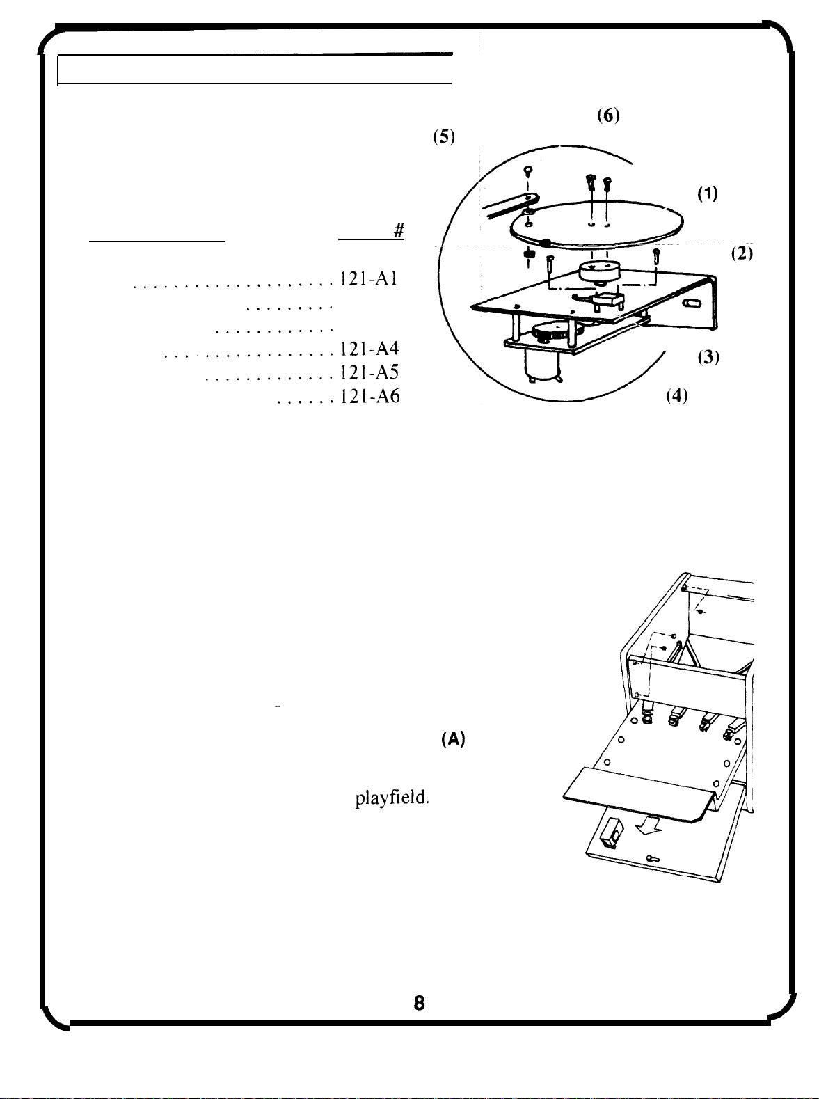
II. ASSEMBLY: ARM MOTOR (BLOWUP)
COIN RAMP MOTOR ASSEMBLY:
DESCRIPTION
PART
1. CAM
2. MAIN BRACKET
3. CAMSWITCH
121-A2
121-A3
4. MOTOR
5. PIVOT LINK
6. SHOULDER SCREW.
TO REMOVE PLAYFIELD (FOR TRUCK SERVICE):
Remove service access trim
1.
(3 security torx screws) then
lift up glass trim.
Next, remove top glass
repeat for other cabinet.
Open front door.
2.
Disconnect harness.
3.
Remove 2 screws on each side of playfield.
4.
Slide piayfield out (A), being careful
5.
not to catch truck on coin ramp motor.
Page 9
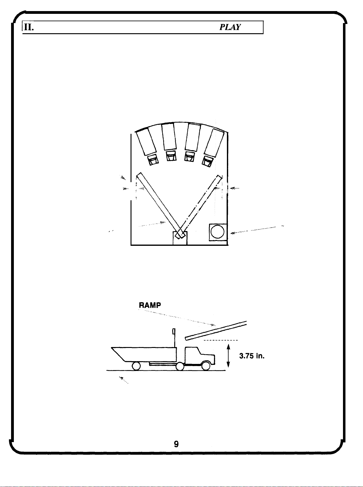
ASSEMBLY: ADJUSTMENTS FOR PROPER
THE DIMENSIONS SHOWN MUST BE
MAINTAINED FOR THE PROPER
COIN COUNT FOR EACH TRUCK.
(MUST BE EQUAL
ON EACH SIDE)
COIN RAMP
COIN RAMP
MOTOR ASSY.
Can be moved to fine
tune equal spacing.
(Note: Motor mount
bracket slotted to allow
for adjustment.)
COIN
PLAYFIELD
Page 10
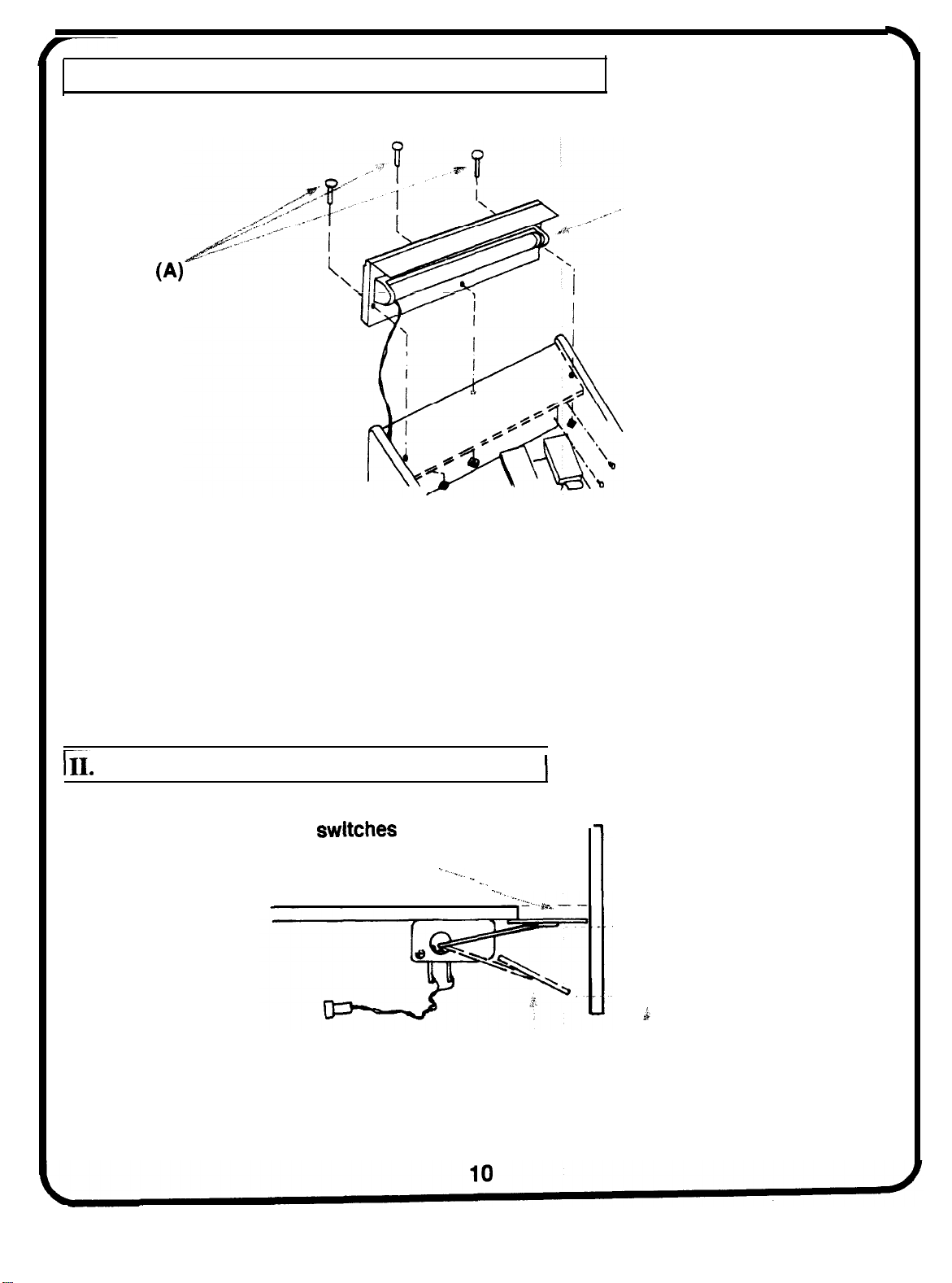
II. ASSEMBLY: FLORESCENT LIGHT FIXTURE
STANDARD 14 WATT
FLORESCENT TUBE
1. Open rear door, unplug fixture.
2. Following previous instructions, remove top glass.
3. Unscrew three carriage bolts
4.
Lift panel up.
(A) (as shown).
ASSEMBLY: COIN MISS SWITCH ASSY.
Both
be open in this
position.
must
approx. 0.8 In
Both switches must
be closed in this
position.
Page 11
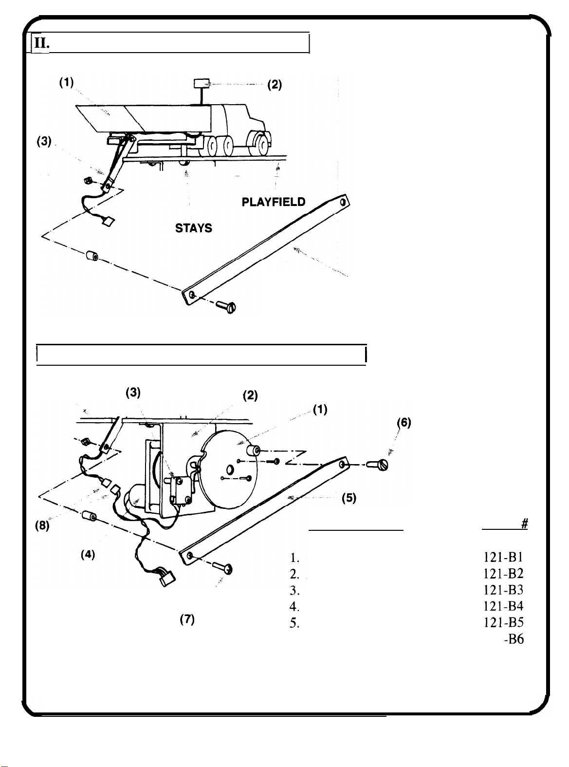
ASSEMBLY: TRUCK BED ASSEMBLY
1.
TRUCK BED
DUMP SWITCH
2.
CARRY ARM
3.
PIVOT
II. ASSEMBLY: TRUCK BED MOTOR ASSEMBLY
PLAYFIELD
.
DESCRIPTION
CAM..
ADJUSTMENT BRACKET . .
CAM SWITCH.. . . . . . . . . . .
MOTOR.. . . . . . . . . . . . . . . .
PIVOT LINK . . . . . . . . . . . . .
SHOULDER SCREW. . . . . . . 12 1
6.
TRUCK BED CONNECTOR SCREW
7.
TRUCK BED MOTOR CONNECTOR
8.
. . . . . . . . . . . . . . . . . .
LINK
PART
11
Page 12
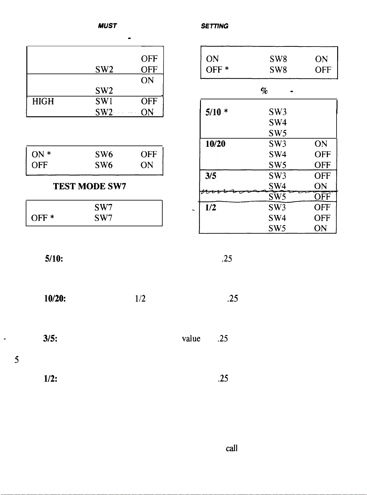
BIG HAUL DIP SWITCH SETTINGS
TURN GAME OFF BEFORE
DIP SWITCHES
MOTOR SPEED SW1
LOW *
MEDIUM
SW1
SW1
ATTRACT SOUND SW6
ON
SW2
OFF
ON
OFF
PAY MERCY TICKET SW8
PAYOUT
SW3
SW5
OFF
OFF
OFF
* DENOTES FACTORY DEFAULT SETTINGS
‘Payout 910:
5 Ticket(s):
10 Ticket(s):
Payout
10 Ticket(s):
20 Ticket(s):
Payout
3
Ticket(s):
Recommended for 1 Cent Ticket value and
(twenty-five) Cent Token value.
Number of tickets issued for each token in truck bed after hitting dump lever.
Number of tickets issued for each token for entering truck bed.
Recommended for
Cent Ticket value and
(twenty-five) Cent Token value.
Number of tickets issued for each token in truck bed after hitting dump lever.
Number of tickets issued for each token for entering truck bed.
Recommended for 2 Cent Ticket
and
(twenty-five) Cent Token value.
Number of tickets issued for each token in truck bed after hitting dump lever.
Ticket(s): Number of tickets issued for each token for entering truck bed.
Payout l/2:
1 Ticket(s):
2 Ticket(s):
When in
Test Mode,
Recommended for 3 Cent Ticket value and
Number of tickets issued for each token in truck bed after hitting dump lever.
Number of tickets issued for each token for entering truck bed.
the bonus lamps will lite to show what truck a token has landed in. This
(twenty-five) Cent Token value.
provides a visual test to see if the timing system and coin counting system is functioning properly.
Mercy Ticket option pays one (1) ticket when active. Please
for additional artwork.
12
Page 13
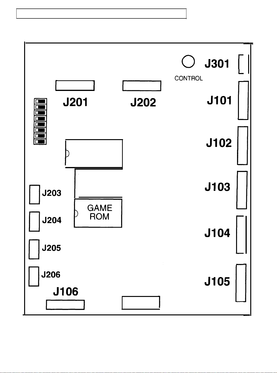
III. SCHEMATICS:
CPU BOARD BLOCK DIAGRAM
DIP
SWITCH
SOUND
ROM
VOLUME
1
J204
CPU BOARD
POWER
13
1
Page 14
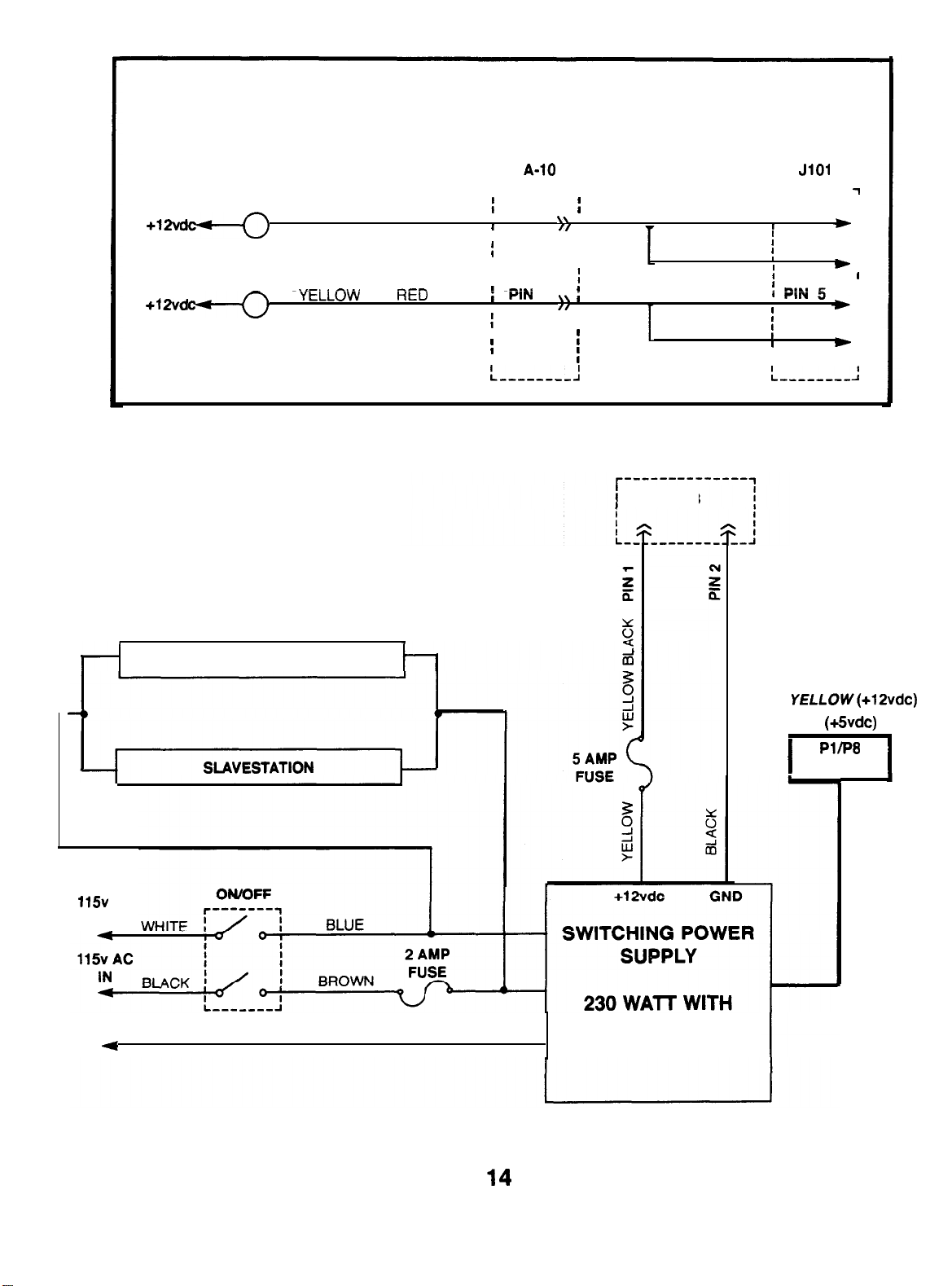
MARQUEE CHASE LAMP
CHASE LAMP SEGMENT 1
CHASE LAMP SEGMENT 2
FLORESCENT LAMPS
MAINSTATION
GRAY ORANGE
r--------i
, PIN 1
I
I
I
I
I
I
3
,
I
I
r--------
I
I PIN 3
I
I
I
I
A-13
PIN 4
PIN 6
I
I
AC
IN
GREEN (GROUND)
RED (+6vdc)
CPU POWER
AUTOOVERLOAD
PROTECTION
NOTE: ALL POWER CONNECTORS ARE NOT USED.
Page 15
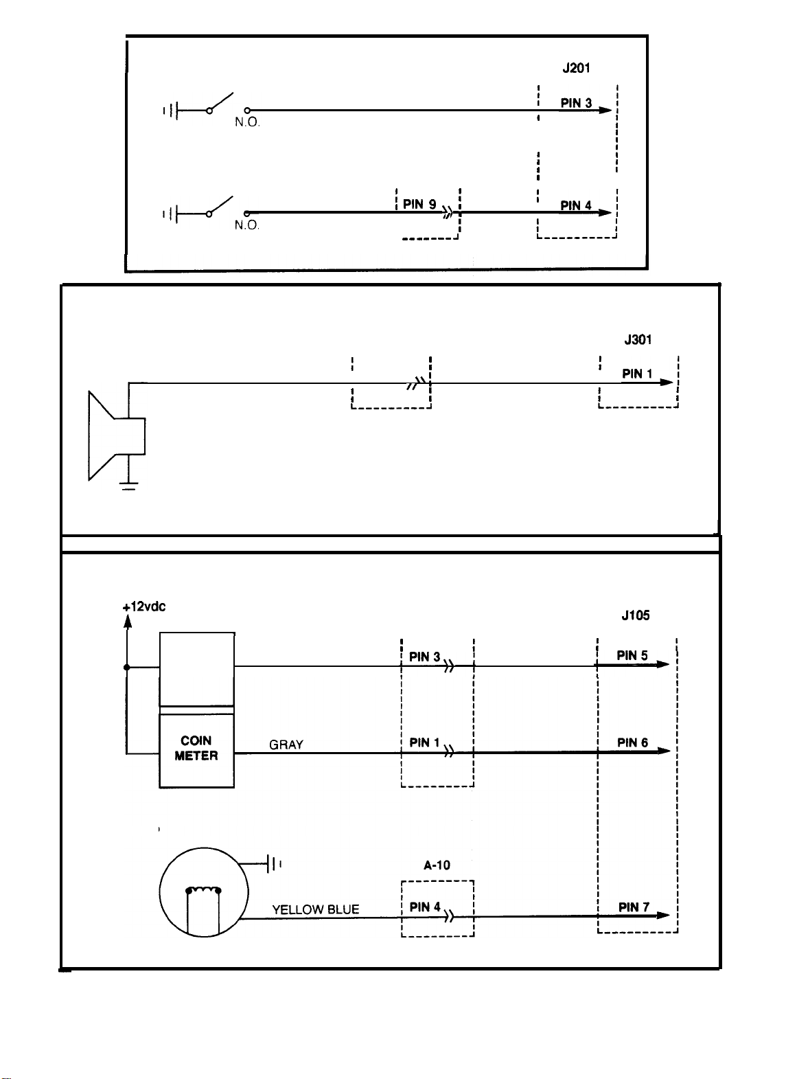
COIN-MEW MAINSTATION
VIOLET
r---------l
I I
I I
I
SPEAKER
COIN-MECH SLAVESTATION
GREEN
YELLOW GRAY
B-7
r-------l
I
L
A-11
r---------i
I PIN 2
I
I
J
I
I
r---------l
I
METERS
STROBE LAMP
TICKET
METER
TAN
A-3
r--------i
r---------l
15
Page 16
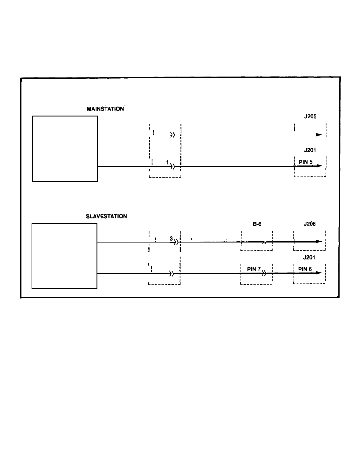
TICKET DISPENSER MAINStATION-
MOTOR ENABLE
TICKET NOTCH
TICKET DISPENSER
MOTOR ENABLE
TICKET DISPENSERS
A-l
r--------7
PIN 3,
PIN
i i
r--------i
PIN
B-3
BLACK WHITE
WHITE
BLUE
r--------i
PIN8,
r--------7
PIN 3
I
i___--_--i
r--------i
r--------i
PIN 3
I
I
TICKET NOTCH
i
I I
PIN 1,
I
i
YELLOW WHITE
B-7
r--------i r--------i
16
Page 17
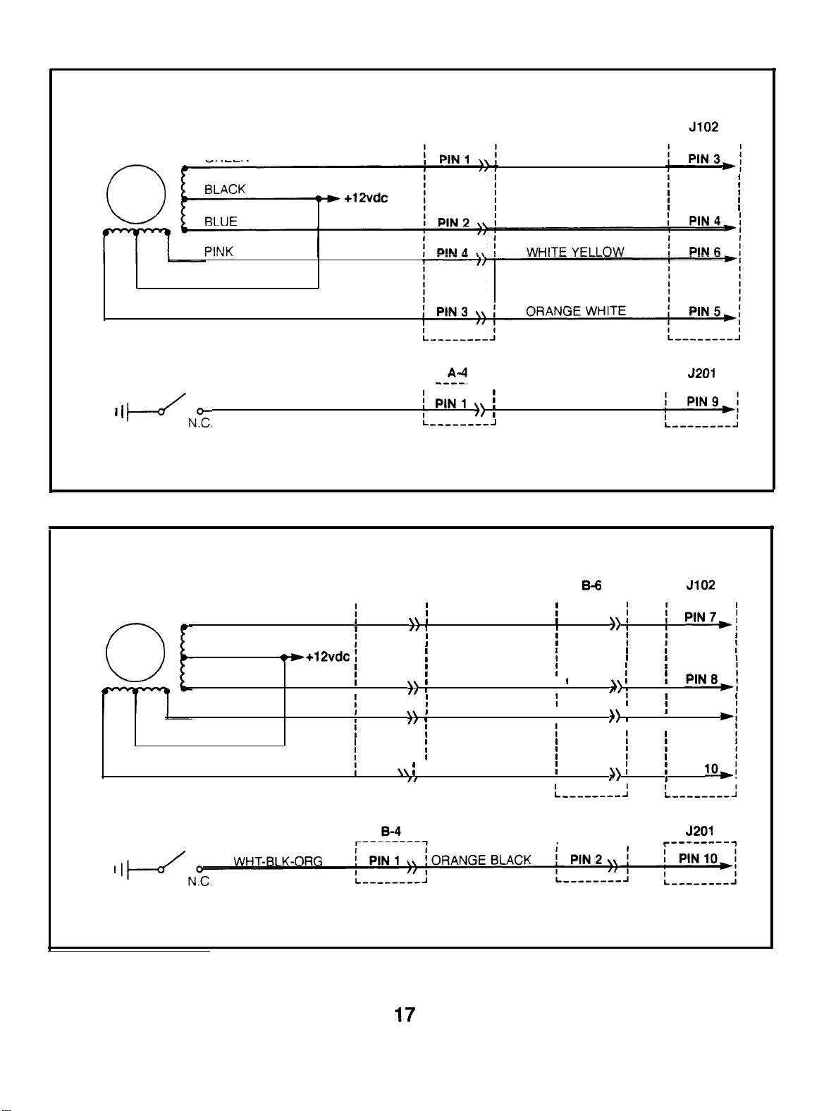
STEPPING
MOTOR
STEPPING-MOTOR RAMP ASSY (MAINSTATION)
A-5
r--------l i---------1
GREEN
WHITE
YELLOW
YELLOW GREEN
YELLOW VIOLET
HOME POSITION SWITCH
WHT-BLK-ORG
STEPPING-MOTOR RAMP ASSY (SLAVESTATION)
STEPPING
MOTOR
GREEN
BLACK
BLUE
PINK
WHITE
YELLOW
r--------i
B-5
r--------l
PIN 1
GRAY GREEN
PIN 2
PIN 4
PIN 3 GRAY YELLOW
I
:_________I
YELLOW ORANGE
BLUE GREEN
,
I
r--------i
WHT-BLK-ORG
r--------i r--------i
PIN 1
PIN 2
I PIN 3
PIN 4
I
,
I
I
I
I
PIN
PIN 9
I
HOME POSITION SWITCH
B-7
r--------i
Page 18
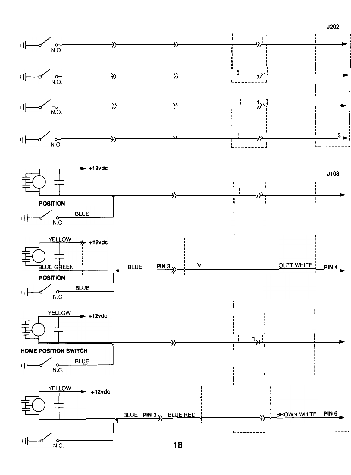
TRUCK DUMP MOTOR ASSY (MAINSTATION)
DUMP LEVER SWITCH (TRUCK 1)
WHITE PIN 1
DUMP LEVER SWITCH (TRUCK 2)
WHITE PIN 1
DUMP LEVER SWITCH (TRUCK 3)
WHITE
DUMP LEVER SWITCH (TRUCK 4)
MOTOR (TRUCK 1)
HOME
WHITE PIN 1
YELLOW
SWITCH
PIN 1
ORANGE PIN 1
ORANGE
ORANGE
ORANGE
BLUE
PIN 1
PIN 1
PIN 1
PIN 3
BROWN
WHT-YEL-BLK
WHT-BLK-VI0
WHT-BLU-BLK
I/
BLUE ORANGE
A-6
r---------i
I PIN 3
BROWN
PIN 12 WHT-YEL-BLK
I
r---------i
PIN
PIN 2 WHT-BLU-BLK ,
r--------i
PIN 5
I
A-9
WHT-BLK-VI0
,
A-6
GREEN WHITE
r---------7
PIN 3
PIN 4
I
PIN 5
PIN
I
r----------
PIN 3
I
,
I
I
I
I
MOTOR (TRUCK 2)
HOME POSKION SWITCH
MOTOR (TRUCK 3)
MOTOR (TRUCK 4)
PIN4
BLUE
PIN 3
i
BLUE YELLOW
PIN
RED WHITE
i
PIN 5
HOME POSITION SWITCH
BLUE
BLUERED
PlN2
i
I
I
I
Page 19
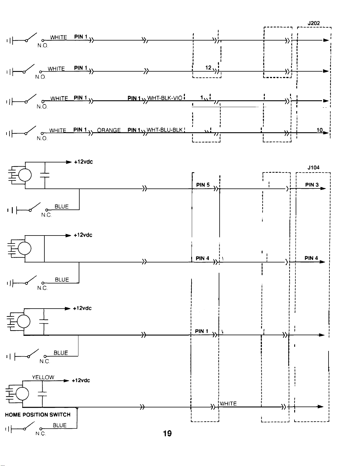
TRUCK DUMP MOTOR ASSY (SLAVESTATION)
DUMP LEVER SWITCH (TRUCK 1)
DUMP LEVER SWITCH (TRUCK 2)
DUMP LEVER SWITCH (TRUCK 3)
DUMP LEVER SWITCH (TRUCK 4)
MOTOR (TRUCK 1)
YELLOW
ORANGE PIN 1
ORANGE
PIN 1
ORANGE PIN
BLUE
PIN 3
BROWN
WHT-YEL-BLK
WHT-BLK-VI0
BLUE ORANGE
B-8 B-7
l--------1
I
PIN 3 ORANGE
PIN
GRAY RED
PIN 8
PIN 12
B-9
l--------1 r-------i
PIN
1
I
PIN 2 WHT-PNK-BLK
YEL-RED-GRN
B-8
-------1
WHT-BLK-BRO
PIN 5
PIN 5
B-6
B-7
PIN 4
I I
PIN 7
PIN 8
I
PIN 9
PIN
L---------J
I
I
HOME POSITION SWITCH
MOTOR (TRUCK 2)
YELLOW
HOME POSITION SWITCH
MOTOR (TRUCK 3)
YELLOW
HOME POSITION SWITCH
BLUE
BLUE
PIN 3
PIN 3
BLUE GREEN
BLUE YELLOW
NHT-BLK-GRN
PIN 5
i
YHT-BLK-RED
PIN 3
PIN 5
I
I
MOTOR (TRUCK 4)
BLUE
PIN 3
BLUE RED
PIN 2
GRAY
PIN 11
I
I
I
PIN 6
I
I
Page 20
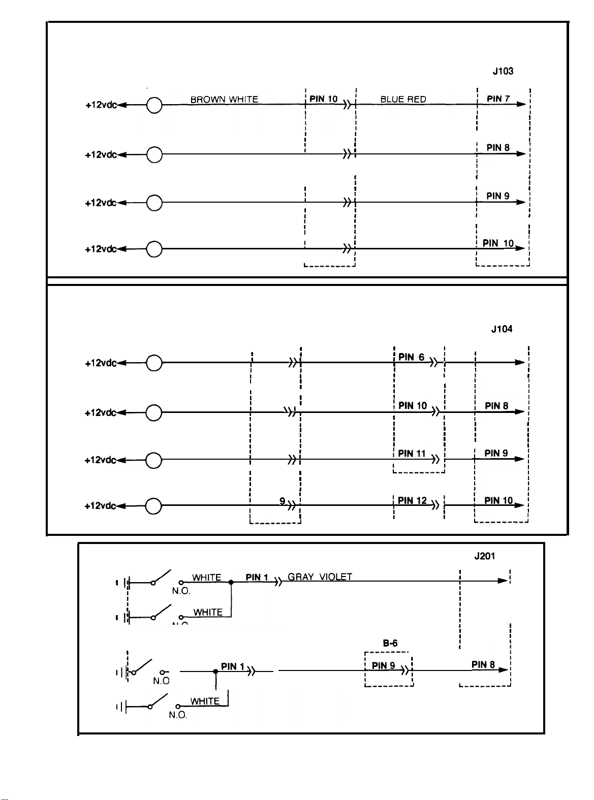
BONUS LAMP 1
BONUS LAMPS (MAINSTATION)
A-8
r--------1
r--------7
BONUS LAMP 2
BONUS LAMP 3
BONUS LAMP 4
BONUS LAMP 1
BONUS LAMP 2
RED WHITE
VIOLET WHITE
GREEN WHITE
PIN 7
I
I
I
I
i
PIN 8
I
I
PIN 9
I
I
I
.
BONUS LAMPS (SLAVESTATION)
B-8
r--------i
BROWN WHITE
RED WHITE
I
PIN 10 WHITE ORANGE
I
PIN 7 WHITE RED
I
BLUE YELLOW
BLUE GRAY
BLUE ORANGE
B-7 J104
r--------1
I I
I
r--------i
I
PIN 7
I
BONUS LAMP 3
BONUS LAMP 4
I
MISS SWITCH (MAINSTATION)
MISS SWITCH (SLAVESTATION)
VIOLET WHITE
GREEN WHITE
N.O.
WHITE
PIN 8
I
PIN
WHITE BLUE
I
WHITE GREEN
GRAYBLACK
r--------i
L ________ J
r--------l
B-6
I
1
r--------l
PIN7
20
 Loading...