

Page 1

Revision
BENCHMARK MEDIA SYSTEMS, INC.
AD2402-96 / AD2K+ TWO CHANNEL, 96-kHz
ANALOG TO DIGITAL CONVERTER
11/09/04 Revision - Absolute Input Polarity Correction pg. 17
Operating Manual
Page 2

AD2402-96 - ANALOG TO DIGITAL CONVERTER
Operating Manual
© BENCHMARK MEDIA SYSTEMS, INC.
5925 Court Street Road
Syracuse, NY 13206-1707
Phone (315) 437-6300• Fax (315) 437-8119
www.benchmarkmedia.com
Page 3

Table of Contents
System Overview 5
Sample Rate 5
Word Length 5
Digital Audio Reference 5
Digital to Digital Processing 6
88.2 and 96 kHz Operation 6
“Dual Cable” 88.2 and 96 kHz Modes 7
“Single Cable” 88.2 and 96 kHz Modes 8
Analog Inputs 8
Meters 8
Power Supply Connection 9
Front Panel 10
“Power” Switch 10
“On” LED 10
“Low Battery” LED 10
“Input Level” Switch 11
“Lock” LED 12
“Word Length Mode” Switch 13
“Sample Rate” Switch 13
“Meter Scale” Switch 15
Digital LED Meters 16
“Aux Output Word Length” Switch 16
“Format” Switch 17
Rear Panel 18
Analog Inputs 18
DC Power Input 19
Fuse 19
Digital Input Connectors 19
“In” Connector 19
“Loop” Connector 21
Digital Outputs 21
Using the Meters 22
Using the Peak Hold Function 22 Digital Outputs 6
Selecting Meter Range 22
Meter Time-Constants 22
Fast Decay Time-Constant 23
Slow Decay Time-Constant 23
“FSD” Meters 24
What is “FSD”? 24
How is “FSD” Different from “0 dBFS”? 24
How is “FSD” Different from “Over”? 24
The Fallacy of “Over” Indicators 25
Do “Over” Indicators Have a Place? 25
Design Philosophy 27
Specifications 28
Jitter and it’s Effects 31
Confusion over Jitter 31
How Does Relate? 31
How Can We Measure Jitter? 31
Why so Low? 32
Jitter Degrades Digital Filters 32
Additional Information 34
Word Length Reduction 35
What is the Appropriate Setting? 35
Page 4

NN™ or NS™ Processes in Cascade 36
Why NN3™ for Cascaded 16-bit? 37
Dither 37
Will Dither Damage My Speakers? 40
How is the Performance Measured? 40
Avoid Truncation without Dither 40
Digital Word Length Increases… 41
Additional Information 41
Word Length Reduction Curves 43
Page 5

AD2402-96 - OPERATING MANUAL
System Overview
A brief overview of the AD2402-96
The AD2402-96 is a 2-channel, portable version of the Benchmark 4-channel AD2404-96 and 8channel AD2408-96 24-bit 96-kHz converters. The Benchmark AD2404 was designed to
provide the best possible sonic performance. The AD2402-96 faithfully replicates this
performance in a portable package.
techniques, and sonic performance of the AD2402-96 are identical to those of the AD2404.
Chapter
The circuit design, components, construction
Sample Rate
The AD2402-96 operates at fixed sample rates of 44.1 48, 88.2 and 96-kHz. In addition, a
“Variable” or “Varispeed” mode allows the converter to operate at any sample rate between 24-
kHz and 100-kHz.
Word Length
Output word lengths can be set at 24, 20, or 16-bits. The 20 and 16-bit word lengths are re-
dithered from 24-bits using either the Benchmark NN™ or NS™ word length reduction
systems. The NN™ and NS™ systems are optimized for the selected sample rate, and for the
number of bits being removed. NN3 and NS3 can achieve near 20-bit performance on a 16-bit
recorder. The NN1, NN2, NS1, NS2, settings are optimized for noisier recording environments.
TPDF (white noise) dither is also a selectable output choice.
96 allows simultaneous 24 and 16-bit outputs.
A unique feature of the AD2402-
Digital Audio Ref erence
A digital audio input jack allows the AD2402-96 to phase-lock to an external AES or SPDIF
digital audio reference. Most 2-channel applications will not require an external reference
and many users will never need to use the external reference input. However, the external
reference is provided to allow phase-accurate multi-track recording with two or more AD2402-96
5
Page 6

AD2402-96 - OPERATING MANUAL
converters. An external reference is also required whenever the converter is operated in the
“Varispeed” mode.
Digital to Digital Processing
The digital audio input jack also serves as the input for all Digital-to-Digital processing
functions.
These functions include; Word Length Reduction, Pro to Consumer and Consumer
to Pro channel-status conversion, SPDIF to AES/EBU and AES/EBU to SPDIF conversion,
SCMS override, and 75 ohm unbalanced to 110 ohm balanced conversion. The D-to-D feature
also allows the AD2402-96 to act as a 1 in 4 out digital distribution amplifier! For processing a
24-bit signal down to 16-bit, as would be the case in mastering a CD or producing a DAT tape,
the user can take the 24-bit signal into the AD2402-96 digital input. Then the user should select
the D-to-D function, and monitor each word length reduction setting to determine which best
complements the recording.
Digital Outputs
Four digital output jacks provide a unique set of features. Two outputs are 75-Ohm
unbalanced, and two outputs are 110-Ohm balanced. All outputs can operate in either
professional or consumer status formats. All outputs support 16, 20, or 24-bits, but the two
“Aux.” outputs can be set to operate at 24-bits while the “Main” outputs operate at either 16, 20,
or 24-bits. All outputs support stereo operation at sample rates up to 100 kHz on a single digital
cable. In addition, a “Main” and “Aux.” output pair can be used to record “dual-cable” 88.2 or
96 kHz.
88.2 and 96 kHz Operation
88.2 and 96 kHz sample rates are supported using either a “Single Cable” interface mode
(also know as “AES3 Multichannel Mode”) or a “Dual Cable” interface mode (also known as
“AES3 Single Channel Double Sampling Frequency Mode”).
6
Page 7

AD2402-96 - OPERATING MANUAL
“Dual Cable” 88.2 and 96 kHz Modes
The “Dual Cable” 88.2 and 96 kHz modes provide a means for recording at sample rates up to
96 kHz on equipment that was originally designed for 48 kHz. When using the “Dual Cable”
mode at 96 kHz, a single audio channel will occupy two tracks on the digital recorder. In this
mode, two successive samples of a single high sample-rate channel are transmitted in place of a
pair of low sample-rate channels. Two digital cables are required for two channels. Using the
“Dual Cable” mode, a standard DAT machine can record one channel at 96 kHz, and an ADAT,
DA88, or other digital multi track devices can record up to 4-channels at 96 kHz.
Caution: Tapes produced in “Dual Cable” mode will appear to be compatible with
standard playback and editing equipment, but actually are not compatible. Do not
use this mode unless you have all of the equipment necessary to edit and play
“Dual Cable” 96 kHz recordings. Any tapes recorded in this mode should be
carefully labeled to avoid confusion. Playback on incompatible systems will
introduce unwanted artifacts that may not be immediately noticeable.
7
Page 8

AD2402-96 - OPERATING MANUAL
“Single Cable” 88.2 and 96 kHz Modes
The “Single Cable” 88.2 and 96 kHz modes are only compatible with digital recorders that are
specifically designed for 88.2 and 96 kHz. In this mode, a channel pair is transmitted on a single
digital cable, at a frame rate equal to the sampling rate.
Analog Inputs
The analog inputs support balanced or unbalanced inputs. Input sensitivity is adjustable in
2 dB steps. Maximum sensitivity is +14 dBu at full scale (0 dBFS). Minimum sensitivity is +24
dBu at full scale (0 dBFS).
Sensitivities greater than +14 dBu have not been included since they would compromise the
dynamic range of the AD2402-96.
Balanced inputs are included since they are the best method of signal interconnection to a
microphone preamplifier, whether the preamplifier has balanced or unbalanced outputs. For
more information on proper cable wiring to receive a signal from an unbalanced source, known
as forward referencing, see page 15 of the Benchmark Media Systems, Inc. application note: “A
Clean Audio Installation Guide”.
The Clean Audio Installation Guide PDF file is available for download from our web site. The
URL is http://www.benchmarkmedia.com/pdf/caig.pdf.
Balanced Inputs: Pin 1 = Shield, Pin 2 = -Signal, and Pin 3 = +Signal (revised).
Unbalanced Inputs: Pin 1 = Shield, Pin 2 = Signal Ground, Pin 3 = Signal (revised).
Caution: Connections from unbalanced outputs will not function properly if
pin 2 on the input to the AD2402-96 is left floating (revised).
Meters
Each conversion channel is equipped with a multi-function 9-segment LED meter. A “Meter
Scale” switch selects either a 6-dB/step scale or a 1-dB/step scale, and controls the peak hold
8
Page 9

AD2402-96 - OPERATING MANUAL
function, which is referenced to the 1-dB/step scale. Metering is fully digital and post conversion
for absolute accuracy.
Po wer Supply Connection
The AD2402-96 is equipped with an industry standard 4-pin XLR power connector, and may be
powered from a 12 V battery, or from an external DC power supply.
The input voltage should be between 11 and 18 VDC.
Pin 1 = Ground,
Pin 4 = +11 to +18 VDC at 0.8 A.
Pins 2 and 3 are not connected internally.
9
Page 10
AD2402-96 - OPERATING MANUAL
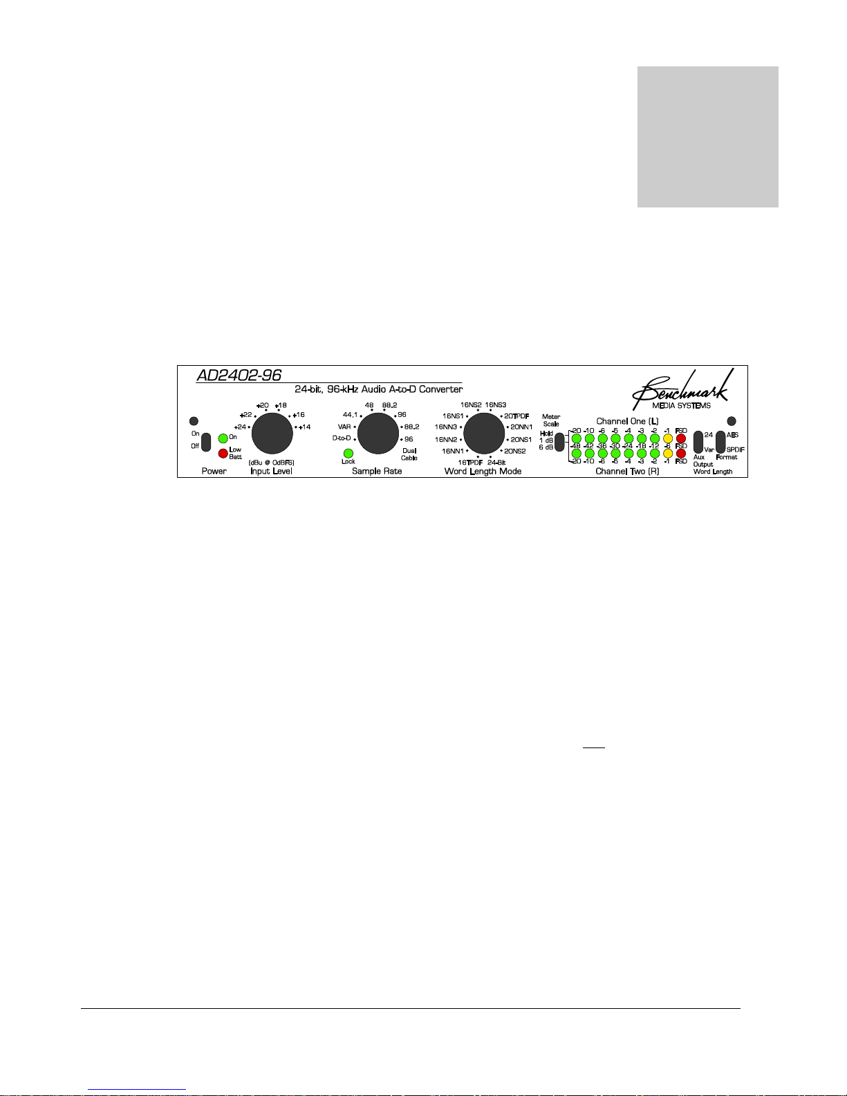
Front Panel
Detailed Information on the AD2402-96 front panel.
Chapter
Figure 1. AD2402-96 Front Panel
“Po wer” Switch
The power switch is equipped with a short handle to prevent accidental shut off. If you are
monitoring the output of the AD2402-96 with headphones or speakers, mute them before turning
this switch on or off. Also, it is a good idea to turn this switch off before connecting or
disconnecting the DC power.
“On” LED
The green “On” LED will light whenever the power switch is on and the input voltage is high
enough for normal operation. The “On” LED will not light if the input voltage is less than 10.5
V. An illuminated “On” LED is your assurance that the input voltage is high enough for normal
operation.
“Low Battery” LED
The AD2402-96 is equipped with a red “Low Batt” LED. The low-battery light is calibrated for
use with 12-volt lead-acid “gel-cell” batteries but may be adjusted for use with other types of
batteries. Lead-acid batteries should be charged shortly after the “Low Batt.” LED turns on. Note
that the AD2402-96 will continue to operate normally as long as the green “On” LED is
10
Page 11

AD2402-96 - OPERATING MANUAL
illuminated. Typically, the AD2402-96 can operate for 1-hr with the red LED illuminated before
the green LED will turn off. However, prolonged and/or frequent deep discharge cycles
(operation with the red LED on) will shorten the lifetime of a lead-acid battery. Lead-acid
batteries should be recharged after every use, and should be stored in a cool location, fully
charged.
“Input Lev el” Switch
This rotary switch adjusts the sensitivity of the analog inputs. The numbers (from +24, down to
+14) indicate the level (in dBu) at which a full-scale digital code will be reached. At “+24” the
converter will clip when the analog input reaches or exceeds +24 dBu. At “+14”, the converter
will clip when the analog input reaches or exceeds +14 dBu.
The “Input Level” switch should be set so that the AD2402-96 will clip 3 to 6 dB before the
microphone preamplifier. For example, if your microphone preamp has a maximum output level
of +24 dBu, then set the switch to “+20”. This will reserve 4 dB of headroom in the preamplifier.
If too much headroom is allowed in the microphone preamplifier, noise from the preamp may
reduce the dynamic range of your recording. If no headroom is provided, the microphone
preamp may add distortion to your recording.
Set the “Input Level” switch to match the performance of your preamp. Do not use this switch to
adjust levels during a recording. Instead, use the gain control on your microphone preamp. This
switch is used specifically to calibrate the AD2402-96 to a line level source, mixing console or
microphone pre-amp. It is NOT intended as a gain control for adjustment during a recording
session. Set the switch in accordance with your pre-amp or mixer before beginning the recording
session.
+24 dBu is a very hot level and is often only available at the output of high quality microphone
preamplifiers. Some battery operated microphone preamps cannot achieve +24 dBu without
clipping, and will require setting the AD2402-96 to a lower clip point (typically “+20” or “+18”).
Use the “+14” setting for unbalanced inputs. Some consumer grade devices are not capable of
achieving even +14 dBu levels without clipping. These low-level unbalanced outputs are not a
good match for the performance of the AD2402-96 but can be connected through an external
balancing interface amplifier if necessary.
All preamplifiers have an intrinsic noise floor that is set by basic physics. The contributing
elements are the source impedance of the microphone, usually between 50 and 200 ohms, the
noise of the first stage of the preamplifier, the noise of second fixed gain stage, and the noise of
the output stage.
A preamplifiers dynamic range is defined by the difference between this intrinsic internal noise
level and the peak output clip point of the preamp. If the clip point is reduced to say + 12 dBu,
and nothing short of miraculous is done to reduce the second and third stage noise of the
preamplifier, the dynamic range of the pre-amp will be limited to much less than the AD2402-96.
11
Page 12

AD2402-96 - OPERATING MANUAL
The only way to achieve a low noise level with the preamplifier is to use extremely low internal
impedances and ultra low-noise operational amplifiers. Both of these required techniques are
power hungry and incompatible with portable pre-amps where long battery life is an objective.
Therefore, avoid microphone preamps that cannot achieve at least +16 dBu out, without clipping.
Even then the dynamic range of the preamp and not the AD2402-96 will, in all probability, be
limiting the dynamic range of your high-quality 24-bit recordings.
“Lock” LED
The “LOCK” LED will turn on whenever the AD2402-96 is locked to a reliable digital audio
reference of the correct frequency. The digital input/reference signal must be AES/EBU or
SPDIF.
The AD2402-96 will lock at 1:1 or 2:1 ratios. For example, if the AD2402-96 is operating at 96
kHz, the converter will lock to either a 48 kHz or 96 kHz digital audio signal.
If the lock light is off, the AD2402-96 is operating as clock master (using the internal crystal
reference).
Important Note:
An external reference is normally not required for 2-channel recording. The lock
LED will not be on when the AD2402-96 is operating as a stand-alone (clock
master) device. This is not an indicator of an error.
A digital audio input is required in the “Var” (variable sample rate) and “D-to-D” (digital to
digital) modes. It is optional in all other modes.
When locking to an external reference, the “Lock” LED will flash for several seconds while
the PLL is acquiring lock and will be lit once internal lock is achieved.
A continuously flashing “Lock” light indicates a lock error.
Possible causes of a lock error include:
• Reference sample frequency is incorrect or out of range.
• Reference signal is neither AES/EBU nor SPDIF.
• Reference signal is being received with errors.
• Reference is required (“Var” and “D-to-D” modes) but is not present.
12
Page 13

AD2402-96 - OPERATING MANUAL
Note: The AD2402-96 automatically mutes for the first 10 seconds after applying
power. While muted, the “Lock” LED will flash nine times indicating that
automatic calibration is in progress. This is not an indication of a lock error.
“Word Length Mode” Switch
The “Word Length Mode” switch is a twelve-position rotary switch. It selects 24, 20, or 16-bit
word lengths at the main outputs. All 16 and 20-bit Word Length Reduction (WLR) modes are
TPDF dithered prior to word length reduction.
There are seven word length reduction modes (“TPDF”, “NN1”, “NN2”, and “NN3”, “NS1”,
“NS2”, and “NS3”). All forms of word length reduction raise the noise floor of a digital
transmission system. TPDF dither is spectrally flat, it is not shaped, and will sound noisier than
any of the “NN” or “NS” modes. “NS1”, “NS2”, and “NS3” are noise-shaping modes which are
psycho-acoustically optimized to take advantage of the ear’s low-level sensitivity curve. “NS1”,
“NS2”, and “NS3” will sound 6, 12, and 18 dB quieter than “TPDF” respectively. “NS1”,
“NS2”, and “NS3” can provide 17-bit, 18-bit, and 19-bit performance respectively at a 16-bit
word length. At 20-bits, “NS1” and “NS2” provide 21-bit and 22-bit performance respectively.
For the best performance, use the maximum word length that is compatible with your digital
audio equipment. Maintain 24 or 20-bit word lengths as long as possible. If WLR to 16-bits
is required, do so at the latest possible point and time. Avoid processing 16-bit signals. In
general, NS2 will produce the quietest 20-bit signal, and NS3 will produce the quietest 16-bit
signal.
Caution: Do not apply word length reduction when using the D-to-D function for
dubbing 16-bit tapes. Use the “24” setting for all D-to-D functions unless you
wish to simultaneously reduce the word length of the input digital audio signal. Use
the “24” setting for 16-bit to 16-bit dubbing, 20-bit to 20-bit dubbing, and 24-bit to
24-bit dubbing. For more information see Table 1.
“Sample Rate” Switch
The “Sample Rate” Switch is a twelve-position rotary switch. This switch selects the sample clock
frequency, the PLL (Phase Locked Loop) mode, dual or single cable interface modes, and digitalto-digital functions.
For typical A/D conversion applications, select either “44.1” or “48”. If an external digital
audio reference is connected to the “Digital Input”, the AD2402-96 will automatically switch from
internal to external clock, and the “Lock” LED will turn on. A feature unique to Benchmark
13
Page 14

AD2402-96 - OPERATING MANUAL
converters is that all automatic transitions between external and internal clock are silent and will
not interrupt the operation of the A/D converter.
For A/D conversion at non-standard frequencies, use the “Var” (varispeed) setting.
In
varispeed mode, the A/D sample rate is determined by the sample rate of the digital audio input
signal. If no digital input is present, the converter will mute, and the digital outputs will default to
44.1 kHz. The “Var” mode supports any sample rate between 28 and 100 kHz but does not have
the jitter immunity provided by the fixed frequency modes. Use fixed frequency mode whenever
possible.
For A/D conversion at high sample-rates using “Single-Cable” interfaces, select either “88.2”
or “96”.
These single-cable 88.2 and 96 kHz settings are labeled in white. These settings are
compatible with high sample-rate recorders that are specifically designed to support single-cable
interfaces.
For A/D conversion at high sample-rates using “Dual-Cable” interfaces, select either “88.2”
“Dual-Cable” or “96” “Dual-Cable”.
These dual-cable 88.2 and 96 kHz settings are labeled in
black. These settings allow high sample-rate recording on 44.1 and 48 kHz recorders. Channel 1
will be directed to the “Main” outputs. Channel 2 will be routed to the “Aux” outputs. Two
tracks will be required for each channel.
Caution: In “Dual Cable” mode, each digital output is dedicated to a single audio
channel instead of a stereo pair. “Dual Cable” recordings require 88.2 and 96 kHz
playback and editing equipment. Furthermore, “Dual Cable” recordings must
always be dubbed and transferred from 44.1 and 48 kHz recorders in the digital
domain. The “Dual Cable” digital output from the recorder must always be mixed,
edited, processed, and converted to analog using 88.2 or 96 kHz equipment. Label
all “Dual-Cable” recordings carefully! A 96 kHz “Dual Cable” recording may
appear to play properly at the analog outputs of a 48 kHz machine, but these analog
output signals will actually contain unwanted alias tones that cannot be removed with
a filter.
For Digital to Digital processing, select “D-to-D”. The “D-to-D” mode provides high-quality
digital to digital processing functions that can be used individually or in combination.
“D-to-D” functions include; word length reduction, SPDIF to AES/EBU format conversion,
AES/EBU to SPDIF format conversion, and SCMS copyright correction. In addition, the
AD2402-96 can act as a 1-in, 4-out digital distribution amplifier.
The digital input will accept either consumer or professional format digital audio. The “Format”
switch always determines the format of all four digital outputs.
14
Page 15

AD2402-96 - OPERATING MANUAL
s
Important Note: If the “Word Length” switch is set at “24”, the “D-to-D” mode
will alter the status bits but will not alter audio data bits. All other “Word Length”
settings will add dither noise to the audio. Use the “24” setting whenever you do
not wish to alter the word length of the audio signal. However, if you wish to
reduce the word length of the audio data, use the “Word Length” switch to select
the desired word length reduction function. See Table 1.
Table 1 - Word Length Mode Settings for D-toD Processing
Input Word LengthOutput Word LengthWord Length Mode Switch Setting
16 16 24
18 16 16N S3, 16NS2, 16NS1, 16 NN3, 16NN2, 16NN1, or 16TPDF
18 18 24
20 16 16N S3, 16NS2, 16NS1, 16 NN3, 16NN2, 16NN1, or 16TPDF
20 20 24
24 16 16N S3, 16NS2, 16NS1, 16 NN3, 16NN2, 16NN1, or 16TPDF
24 20 20N S2, 20NS1, 20NN1, 20TPDF
24 24 24
“Meter Scale” Switch
The “Meter Scale” switch selects one of three digital meter functions. The down position sets
the meter scale to 6-dB steps. The center position sets the meter scale to 1-dB steps. The up
position sets the meter scale to 1-dB steps with peak hold. Moving the switch to the center
position will clear the peak hold. Note that the bottom of the 1-dB scale is expanded and includes
a -20 dBFS LED that can be used to set the input level relative to a 0-dB house reference. The “6
dB” setting makes it easy to verify that signals are present at the analog inputs. The “1 dB”
and “Hold” settings permit accurate monitoring near full scale.
15
Page 16

AD2402-96 - OPERATING MANUAL
Digital LED Meters
Each conversion channel is equipped with a multi-function 9-segment LED meter. A “Meter
Scale” switch selects either a 6 dB/step or 1 dB/step scale and controls the peak hold function.
Metering is fully digital and post conversion for absolute accuracy.
Time constants are built into the meters so that all transient peaks can be observed easily. If a
transient peak having a duration as short as one digital sample occurs, an LED will be illuminated,
and will stay illuminated long enough to be observed by the human eye.
A peak indication mimics the action of the needle on a peak-reading analog meter, while the
remaining LEDs will follow the instantaneous level of the audio.
The red “FSD” (Full-Scale-Digital) LED indicates that a full-scale digital code has been reached
and that digital clipping has occurred. Full-scale events as short as one digital sample, will light the
“FSD” LED. Short single-sample digital clipping events are often audible, and all “FSD” events
should be avoided.
The AD2402-96 has a very large dynamic range (especially when operating at 24-bit
output word lengths). It is wise to use some of this dynamic range to provide more
headroom as insurance against clipping. Leave some extra headroom between your
highest anticipated peak and the red “FSD” LED.
“ Aux Output Word Length” Switch
This two-position toggle switch controls the word length of the auxiliary digital outputs. This
switch allows simultaneous recording at 24-bits and 16-bits, or at 24-bits and 20-bits.
When the “Aux Out Word Length” switch is set to “24” the auxiliary outputs will always operate
at 24-bits, while the “Word Length Mode” switch will control only the “Main” outputs. When the
“Aux Out Word Length” switch is set to “Var”, the “Word Length Mode” switch controls all
outputs.
The “Aux Output Word Length” switch has no function when the “Sample Rate”
switch is set to one of the “Dual Cable” settings. In “Dual Cable” mode, the “Word
Length Mode” switch controls the word length of all outputs.
16
Page 17

AD2402-96 - OPERATING MANUAL
“Format” Switch
The two-position “Format” switch controls the format of the digital outputs. The “AES” position
sets the status bits to professional (AES-3) format. The “SPDIF” position set the status bits to
consumer (IEC 60958-1) format.
Many “professional” recorders can accept either professional or consumer formats.
However, many “consumer” recorders cannot accept professional formats. In most
cases, the “S/PDIF” setting will allow simultaneous output to both “professional”
and “consumer” devices on both XLR and BNC or RCA (coax) cables.
Consumer status bit formats do not currently have the capability of identifying 88.2
or 96 kHz sample rates. Consequently it is advisable to use the “AES” (professional)
format setting for all 88.2 and 96 kHz recordings.
17
Page 18
AD2402-96 - OPERATING MANUAL
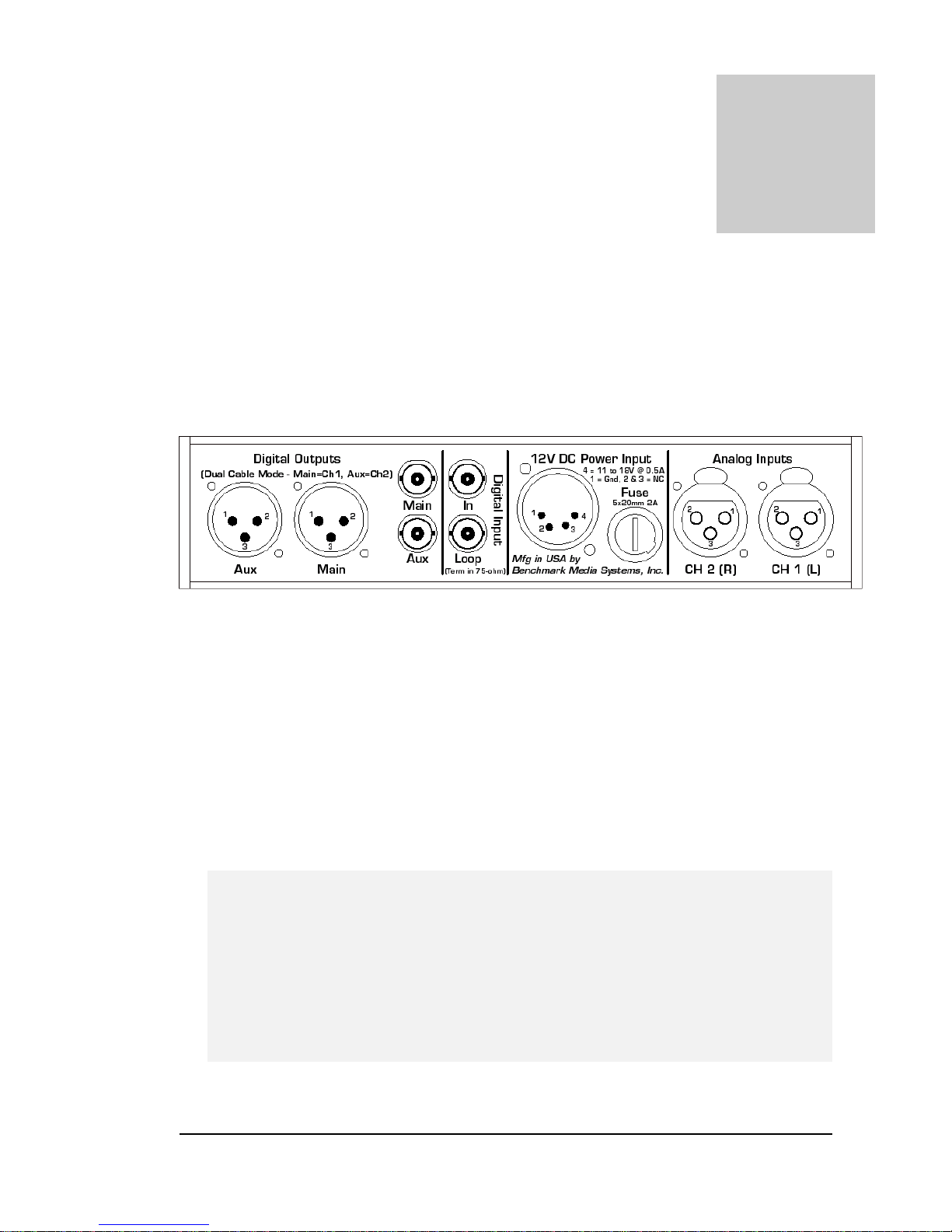
Rear Panel
Detailed Information on the AD2402-96 Rear Panel.
Chapter
Figure 2. AD2402-96 Rear Panel
Analog Inputs
The analog inputs support balanced or unbalanced inputs. Input sensitivity is adjustable in 2
dB steps. Maximum sensitivity is +14 dBu at full scale (0 dBFS). Minimum sensitivity is +24 dBu
at full scale (0 dBFS).
PLEASE NOTE: An internal absolute polarity inversion error was discovered some time
after the creation of the AD2402-96/AD2K+. The following table is revised from the
original and should be used instead of the original table.
Balanced Inputs: Pin 1 = Shield, Pin 2 = -Signal, and Pin 3 = +Signal.
Unbalanced Inputs: Pin 1 = Shield, Pin 2 = Signal Ground, Pin 3 = Signal.
Caution: Unbalanced inputs will not function properly if pin 2 is left unconnected.
18
Page 19

AD2402-96 - OPERATING MANUAL
DC Po wer Input
The AD2402-96 is equipped with an industry standard 4-pin XLR type power connector, and may
be powered from a 12 V battery, or from an external DC power supply.
The input voltage should be between 11 and 18 VDC.
Pin 1 = Ground
Pin 4 = +11 to +18 VDC at 0.8 A.
Pins 2 and 3 are not connected internally.
Fuse
The AD2402-96 is equipped with a 2-Amp fuse. This fuse is designed to blow if the AD2402-96
is connected to improper voltages and/or in reverse polarity. It is important to use an exact
replacement.
Digital Input Connectors
“In” Connector
This BNC connector provides a digital audio input to the AD2402-96. The digital audio input has
two functions: It can provide a phase and frequency reference to the AD2402-96 sampling
circuitry, or it can serve as an input for Digital–to-Digital processing functions.
All digital inputs and outputs are transformer coupled. The transformers isolate the
AD2402-96 from RF interference, provide protection against transients, and isolate
the internal circuitry from the effects of ground loops. DC blocking capacitors are
included to protect against damage from improper connections to phantom supplies,
or digital microphone supplies.
Use 110-ohm digital audio cable for XLR connections, and 75-ohm coax for BNC
and RCA connections. Incorrect cable impedances may increase jitter, may cause
19
Page 20

AD2402-96 - OPERATING MANUAL
data loss, and will reduce the maximum transmission distances. Standard analog
audio cable should not be used for digital signals.
The Digital “In” connector accepts either professional or consumer status bit formats. The PLL
automatically supports 1:1, and 2:1 lock ratios when a fixed sample rate is selected. In other
words, a 48-kHz digital audio signal may be used as a reference when the converter is operating at
96 kHz. However, the varispeed mode (“VAR”) requires a 1:1 lock ratio.
A digital audio input is required when:
• The converter will be operating in a variable speed mode (“VAR 1:1”).
• More than two channels must be phase locked together.
• The converter is to be locked to an external studio reference.
• The digital-to-digital (“D-to-D”) mode is selected.
If a reference is required, but no reference input is detected, the “LOCK” LED will flash
rapidly. If a reference is present, but lock has not been achieved, the “LOCK” LED will flash
slowly.
Note: Using an external reference will not degrade or alter the low-jitter performance
of the AD2402-96 converter at any of the fixed sample rates. The jitter
performance of the fixed sample rate modes is maintained even when the
reference has relatively high levels of jitter.
However, the “VAR” variable speed mode has a wide frequency range that
precludes the use of the final VCXO stage of the AD2402-96 PLL. If a variable
speed mode is used, it is important to provide a low-jitter reference signal. Use
the fixed sample rate settings whenever possible.
Digital-to-Digital processing functions include;
Word Length Reduction, Pro to Consumer and
Consumer to Pro channel-status conversion, SPDIF to AES/EBU and AES/EBU to SPDIF
conversion, SCMS override, and 75 ohm unbalanced to 110 ohm balanced conversion. The D-toD feature also allows the AD2402-96 to act as a 1 in 4 out digital distribution amplifier.
In most 2-channel recording applications it is not necessary to connect a signal
to the “Digital Input” connectors.
20
Page 21

AD2402-96 - OPERATING MANUAL
The digital input will only accept digital audio signals, and will automatically
recognize either professional or consumer formats. It will not respond to non-audio
signals such as word clock, super clock, or video.
“Loop” Connector
This BNC connector is p
rovided to allow looping (or daisy chaining). The “In” and “Loop”
connectors are directly connected to each other, and are transformer coupled to a high-impedance
digital input circuit. The internal digital circuit does not place a significant load on the digital input
connectors. This high-impedance design allows looping without degrading the quality of the digital
input signal.
One digital audio reference signal can be looped through multiple AD2402-96 converters to
provide phase accurate multi-track recording capability. Or, one digital-audio source can be looped
through one or more AD2402-96 converters to provide a large digital-to-digital fan out for
dubbing. If the loop feature is not being used, a 75-Ohm termination should be connected to the
“Loop” connector (a 75-Ohm termination is supplied with the AD2402-96).
Digital Outputs
Four digital output jacks provide a unique set of features.
at 1 Vpp, and two outputs are 110 Ohm balanced at 4 Vpp. All outputs can operate in either
professional or consumer status formats. All outputs support 16, 20, or 24-bits, but the two “Aux”
outputs can be set to operate at 24-bits while the “Main” outputs operate at either 16 20, or 24bits. All outputs support stereo operation at sample rates up to 100 kHz on a single digital cable.
In addition, a “Main” and “Aux” output pair can be used to record “dual-cable” 88.2 or 96 kHz.
Two outputs are 75 Ohm unbalanced
The 75-ohm BNC connectors support SPDIF consumer format, as well as AES3-id and SMPTE
276M professional formats. The 75-ohm interfaces are well suited for long cable runs, and can
easily achieve transmission distances of 1000 feet without cable EQ, and 3000 feet with cable EQ.
AES3-id and SMPTE 276M use identical data formats and are fully inter-operable.
21
Page 22

AD2402-96 - OPERATING MANUAL
Chapter
Using the Meters
9-Segment LED Meters.
he AD2402-96 has a nine-segment LED meter for each audio channel. The meters are
fully digital and respond to both positive and negative going peaks. Thresholds are
T
sample can be displayed and measured accurately. The “FSD” clip indicator is accurate to one
quantization level.
determined by digital comparators, and therefore are exactly matched between channels.
Dual time constants extend the on time of each LED so that peaks as short at only one
Using the Peak Hold Function
Moving the meter control switch all the way up enables the peak hold function. This sets the
slow time constant to infinity. The highest peak will be held, all segments below the peak level
will be controlled by the fast (7.8 msec) decay time constant.
Selecting Meter Range
The AD2402-96 has two meter ranges; one with 6-dB steps, and one with 1-dB steps. The 6-dB
scale allows monitoring for signal presence, as well as coarse adjustment of levels. The 1-dB scale
allows highly accurate adjustment of digital levels. In addition, the bottom two steps of both
scales are expanded.
In either range, a light will not light until the appropriate threshold is reached. In other words,
the -1 dBFS light will remain off until a digital code equal to or exceeding - 1 dBFS is
encountered. Therefore, a signal at -1.01 dBFS will read -2 dBFS on the meter. This guarantees
that the step between -2 and -1 is the same size as the step between -1 and FSD.
Meter Time-Constants
The meters on the AD2402-96 have instantaneous peak response. In other words, the amplitude
of a single sample will read accurately on the meter. However, the response time of the human
22
Page 23

AD2402-96 - OPERATING MANUAL
eye is much too slow to allow us to see an LED light up for one sample of a 44.1 kHz or 48 kHz
clock. Therefore, the meters on the AD2402-96 incorporate a decay time constant which extends
the on-time of all LEDs, and a second slower time constant which extends the on time of the
highest LED triggered by a peak. Even the shortest transient can be observed.
Fast Decay Time-Constant
The fast time-constant is active in all meter modes. Its purpose is to compensate for the relatively
slow response of the human eye. Here is how it works: If any segment of the LED meter turns
on, it and all of the segments below it, are held on for 375 samples (or 7.8 msec). This 7.8 msec
“on-time” is just long enough to make the LED clearly visible to the human eye. At the end of
the 7.8-msec delay, the first time constant releases its control of the meter segments. If a higher
peak should occur during the 7.8 msec interval, this new peak will be displayed, and the 7.8 msec
timer will restart. Thus no peaks are ever missed, and all are visible.
Slow Decay Time-Constant
The slow time-constant is active whenever the peak hold function is off. After the first time
constant releases control of the meter segments, a second 0.5-sec time constant will continue to
keep the highest illuminated LED lit. All meter segments below this LED will continue to display
peaks using the 7.8 msec time constant. At the end of 0.5 sec, the highest illuminated LED will
shut off, and the LED below it will turn on. This will restart the 0.5-sec timer. Thus, peaks will
decay at a rate of one-meter segment every 0.5 seconds. However, if at any time, an audio peak
occurs which is higher than the one being held the new peak will be held and the timer will
restart. Again, no peaks are lost, and all are visible.
23
Page 24

AD2402-96 - OPERATING MANUAL
Chapter
“FSD” Meters
What is “FSD”?
There are several different ways of labeling the clip LED on a digital meter. These include; 0
dBFS, Clip, Over, and FSD.
“FSD” stands for “Full Scale Digital” and has a very specific and slightly different meaning than
“0 dBFS”, or “Over”. It is important to understand the difference.
The “FSD” indicator will light whenever the minimum or maximum digital code of the converter
is reached for a duration of one sample or more. No other digital codes will ever cause the “FSD”
indicator to light.
How is “FSD” Different from “0 dBFS”?
Ideally there is no difference, but in practice, 0 dBFS has often been used to describe any digital
code which is very close to full scale. “FSD” is used to describe only the minimum and maximum
digital code.
An “FSD” meter must have knowledge of the digital word length in order to work properly. A
16-bit “FSD” code will not register “FSD” when feeding a “FSD” meter that is expecting a 20-bit
word length. The reason for this is that the 16-bit word will have 4 trailing zeros appended to it
(to make it a 20-bits word), and the 20-bit “FSD” meter will interpret this as a level which is 16
codes below full scale. Fortunately testing for non-changing trailing bits easily solves this problem.
How is “FSD” Different from “Over”?
An “Over” indicator (as specified in the Sony 1630 OVER standard) will only light if a minimum
or maximum digital code is reached for three or more consecutive samples. One or two
consecutive full-scale digital codes are not considered an “Over”. Some “Over” meters deviate
from the Sony standard and allow the selection 4, 5, or 6 contiguous full scale codes before
indicating an over.
24
Page 25
AD2402-96 - OPERATING MANUAL
The Fallacy of “Over” Indicators
“Over” indicators are based upon the assumption that a digital clip cannot be heard if it has a
duration of three or less consecutive samples. Unfortunately “over” meters will ignore many
audible overloads, and are poorly suited for 24-bit recording.
There is a high probability that a musical signal can clip over a duration of many samples without
ever clipping on three successive samples. The reason for this is that the sensitivity of “Over”
meters is a function of frequency. In fact, “over” meters are very insensitive to certain
frequencies. For example, at a 44.1 kHz sample rate, a 10 kHz tone will not cause three
consecutive full-scale codes until it is severely clipped. Given a complex musical signal, the
reliability of an “over” meter can best be described as “hit or miss”.
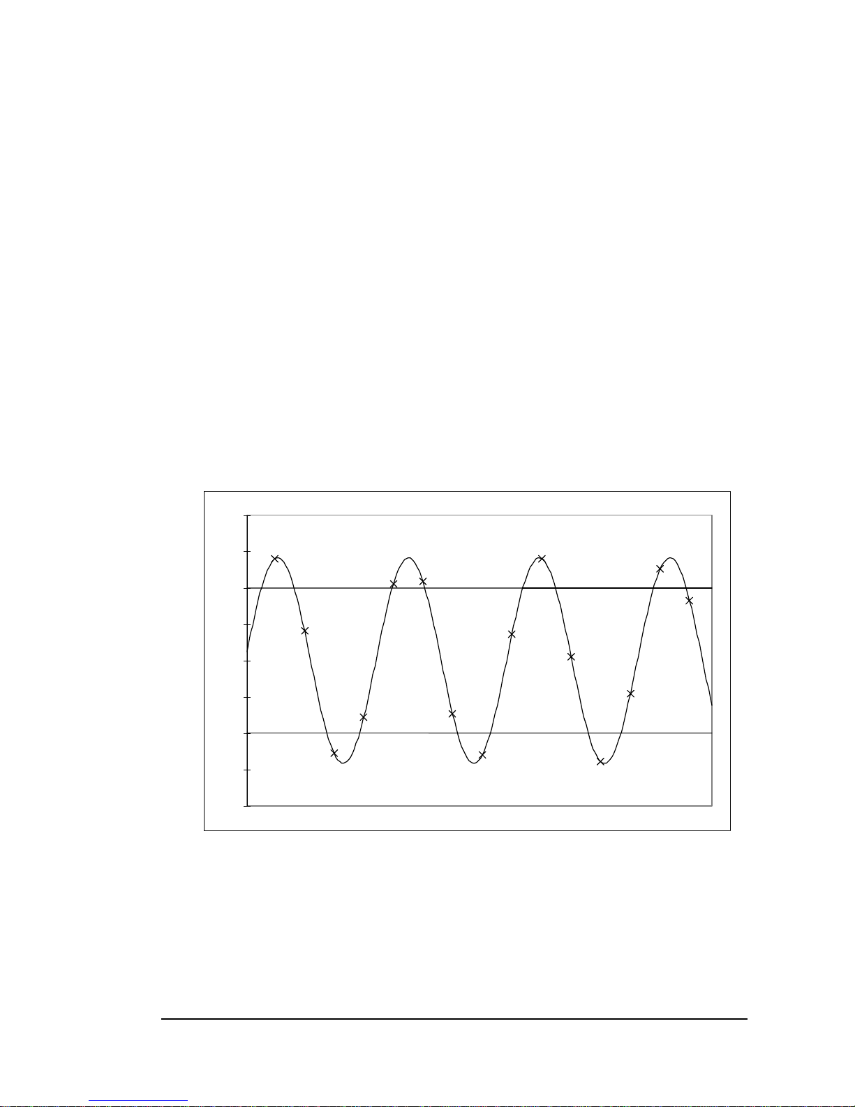
If you have an “over” meter, try this. Feed a 10 kHz tone into any A to D converter at a level
equivalent to +3 dBFS. As shown in the graph below, peak voltages will reach almost 1.5 times
clip level. This clipping will cause severe harmonics at 20 kHz, and distortion will exceed 14%.
The resulting distortion will sound really nasty, but the “over” meter will not detect the clipping.
A close examination of the graph will show that under these circumstances, 3 consecutive fullscale codes can never occur.
2
1.5
1
0.5
0
-0.5
-1
-1.5
-2
FIGURE 3. 10 kHz TONE AT +3 dBFS (1 AND -1 REPRESENT CLIP LEVELS)
Do “Over” Indicators Have a Place?
Over meters may be useful when creating very “hot” 16-bit masters. It is our contention that they
should not be used for recording.
25
Page 26

AD2402-96 - OPERATING MANUAL
In spite of our best efforts to produce clean audio, there is always a demand for a CD that is as
loud or louder than other CDs. The truth is, 16-bit masters that are created using “Over” meters
may end up 3 dB hotter than masters that are created using FSD metering. What often happens,
is that “Over” meters will allow clipping of the highest peaks (by about 3 dB). In most cases, this
clipping is audible. But, the CD will sound louder and sometimes that is all that seems to matter.
A suggestion: Keep the original recording clean by using a FSD meter. Create a final 20 or 24-bit
mix entirely with FSD meters. Then and only then, transfer to 16-bits (using an appropriate dither
process), and adjust the levels using an “Over” meter. This way, if the clipping proves
objectionable, you can still go back to the clean mix and repeat the transfer. Better yet, avoid the
use of an “Over” meter entirely. Whenever you are being pressed to achieve maximum loudness,
use one of the digital loudness processors.
26
Page 27

AD2402-96 - OPERATING MANUAL
Design Philosophy
Our Goals and Design Methodology
he AD2402-96R was designed by John Siau, Allen H. Burdick, and Ralph Henry at
Benchmark Media Systems, Inc. It is carefully engineered to reliably provide the highest
T
piece of wire as possible.
possible audio transparency. We have not tried to add “warmth” or “color” to the audio.
Instead, we have attempted to produce a piece of equipment that sounds as close to a
Chapter
Converters are often viewed as digital products, and are most often designed by digital hardware
and software engineers without adequate attention to the analog sections. The importance of the
analog circuitry is often overlooked, and the resulting defects easily go undetected.
Unfortunately, given time, our ears usually detect these defects.
Our ears have a dynamic range of about 130 dB, and we can hear tones 20 to 30 dB below white
noise. The presence of noise may allow audible defects to escape the scrutiny of many bench
tests. We can hear multiple tones at various amplitudes simultaneously. Many audio
measurements are only capable of measuring the tone having the highest amplitude. Again,
bench tests can ignore critical information!
Because bench tests have often failed to detect audio defects, some have discounted their value
and have relied solely on listening tests. We believe listening tests are a valuable tool for
evaluating a finished product and for confirming the validity of a careful and thorough bench
testing/development cycle. The key is; we must employ test techniques that expose all audio defects. Then
these defects can be eliminated or reduced long before they could be detected through listening
tests and/or field use.
Our experience shows that a careful and thorough bench testing/development program enables
us to produce products that sound right the first time. It is important to note that specifications
can be very misleading. Each spec by itself only paints a small picture of the total performance
that can be expected. It is quite possible to select certain tests, test signals, frequencies, levels, and
parameters that make a given product look good on a spec sheet. It is also our view that
specifications should never be selected for marketing purposes. Product specifications should be
comprehensive, and should include graphs and FFT plots. Bench testing must be viewed as a
product development tool, and not as a marketing tool.
27
Page 28
AD2402-96 - OPERATING MANUAL
Appendix
Specifications
Sample rates = 44.1, 48, 88.2, 96 kHz, and variable
THD + N = -107 dBFS (0.00033%) at -1 dBFS
Dynamic range = 117 dB, A weighted
Conversion Jitter = 9 Pico Sec., typical
Word length reduction = 7 settings for 16-bit output,
4 settings for 20-bit output
Outputs = 2 AES (XLR) and 2 S/PDIF (BNC)
(Simultaneous 24-bit & 16-bit DAT outputs possible)
88.2 or 96 kHz = single or dual-cable output
Analog inputs = balanced XLR
Input level for 0dBFS = +14 to +24 dBu - switch selectable
Metering = 9-segment, fully digital with “peak-hold”
Digital Input = 75-ohm loop-through (high Z)
D-to-D = word length reduction/format conversion
D-to-D & Reference = AES/EBU or S/PDIF format
Power = +12 to +18 VDC, 4-pin XLR connector
Current drain = 800 mA max, Fuse = 5x20 mm, 2 A
Low Battery indicators = 11.5 V red on, 10.5 green off
Chassis = 8"W x 5"D x 1 3/4"H, weight 1.98 lb., 0.897 kg
R.F. Emissions = complies with CE and FCC “B” requirements
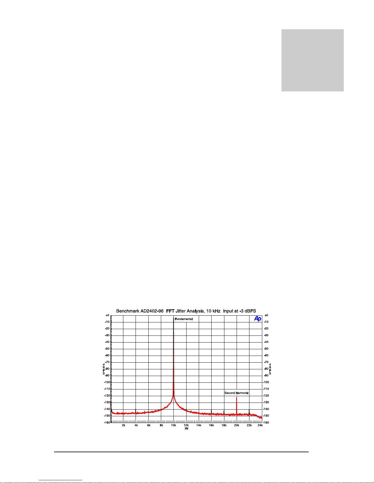
FIGURE 4. AD2402-96 JITTER ANALYSIS
28
Page 29
AD2402-96 - OPERATING MANUAL
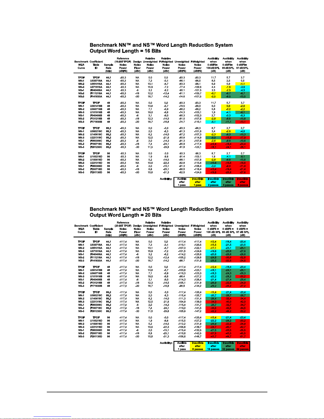
BIT NOISE BUILDUP VS NN™ AND NS™ VS NUMBER OF PASSES
16-
20-BIT NOISE BUILDUP VS NN™ AND NS™ CURVES VS NUMBER OF PASSES
29
Page 30
AD2402-96 - OPERATING MANUAL
30
Page 31

AD2402-96 - OPERATING MANUAL
Appendix
Jitter and it’s Effects
Much Confusion Exists over Jitter: How and Where to Measure It, and How to
Eliminate It
The phase modulation effects of sample clock jitter in any A-to-D converter become a
permanent part of your recording. For that reason, great effort has been invested eliminating
sample clock jitter in the Benchmark A-to-D converters. A unique and proprietary Phase
Lock Loop keeps the converters virtually free from sample clock jitter, under all operating
conditions. Clock jitter at the converter’s sample and hold is typically 9 Pico-seconds RMS (9
trillionths of a second) measured over a bandwidth of 20 Hz to 12.288 MHz. Remember,
sample clock jitter in either an A-to-D or D-to-A converter can have a devastating effect on
the audio.
How Does Sample-Clock Jitter Relate to Interface Jitter Measured at the
AES/EBU or SMPTE Output Connectors?
Sample clock jitter cannot be measured at an AES/EBU or SMPTE output connector. The
reason is simple: AES interface standards require bandwidth and rise-time limiting in order
to reduce electromagnetic interference. As a result, the AES interface will add codedependent jitter, which may be 100 to 1000 times greater than the jitter at the converter’s
sample and hold. This is potentially inconsequential. This interface jitter accumulates after
the audio is in the digital domain, and therefore, does not degrade the audio signal, provided
it is removed prior to D-to-A conversion. But, unlike interface jitter, sample clock jitter
cannot be removed. Therefore it is critical to measure the sample clock jitter by itself.
How Can We Measure 9 Pico-Seconds of Jitter or Less?
Sample clock jitter can be isolated and measured to a resolution better than 2 psec using a
16,000 point FFT analysis of the 24-bit digital audio output of an A-to-D converter. If, for
instance, a -1 dBFS 10 kHz high purity test tone is connected to the analog input of an A-toD converter, sample clock jitter of 16 psec will produce spurious tones (side bands from the
jitter’s phase modulation effect) which have a total energy of -123 dBFS. If the jitter energy
is concentrated at a single frequency, as is often the case, two side bands will be produced,
one on either side of the 10 kHz test tone. Each side band will have an amplitude of -129
dBFS. Although -129 dBFS is an extremely low level, it is still within the resolving ability of
31
Page 32

AD2402-96 - OPERATING MANUAL
most 24-bit A-to-D converters. This is important because our ears act much like a super
resolving FFT analyzer.
Why Does Sample-Clock Jitter Need to be so Low?
It can be easily demonstrated that most people have the ability to detect and identify tones
which are buried 25 dB or more below white noise (A-Weighted). Therefore, it is important
to keep jitter induced side bands nearly 25 dB below the A-Weighted THD+N of the
converter, otherwise the jitter may become audible.
Jitter can only be considered totally inaudible if the worst case jitter induced sidebands are at
least 23 dB below the A-weighted system noise. Above this level jitter may be audible or it
may be masked by the program audio. At Benchmark our goal is to achieve totally inaudible
levels of jitter.
The FFT analysis shown in Figure 4 demonstrates the ability of the AD2402-96 to resolve
tones as low as -140 dBFS. Note that in this test, the AD2402-96’s highest jitter induced side
bands occur at 4 kHz and 6 kHz. These each measure at an extremely low -140 dBFS and
indicate that jitter at 6 kHz (a common problem frequency) is below 5 Pico-seconds. The
AD2402-96 has an idle channel THD+N of better than -117 dBFS (A-Weighted) and jitter
induced side bands are held 23 dB below this level. It is this level of performance, which
makes the AD2402-96 unique.
Jitter Degrades Digital Anti-Alias Filters
The performance of oversampled A/D converters is highly dependent upon very precise
digital filters. These digital filters provide a brick wall that stops unwanted high frequency
signals. In the case of 44.1 kHz conversion, this brick wall filter is constructed such that it
stops all frequencies above 22.05 kHz (one half of the sample rate). Frequencies above
22.05 kHz cannot be represented in a 44.1 kHz digital system. If these frequencies are not
removed, aliasing will occur. When aliasing occurs, high frequency information is translated
or folded back into the audio band.
Oversampled converters use digital filters to prevent aliasing, non-oversampled converters
rely solely upon analog filters in front of the A/D sample and hold circuit. Analog filters
require closely matched resistors and capacitors, parts with low temperature coefficients, and
lots of space on a circuit board. A digital filter can easily outperform the best analog filter.
Digital filter performance is generally limited only by the number of arithmetic operations
that we are willing to perform for each sample of audio that passes through the filter. State
of the art A/D converter ICs have digital filters that can achieve remarkable levels of
performance. For example, at a 44.1 kHz sample rate, the digital anti-alias filter in the
AD2402-96 achieves 117 dB of attenuation at all frequencies between 24.44022 kHz and
2.798145 MHz while the response at 20.30364 kHz is –0.01 dB! However, this performance
can only be achieved in the absence of jitter.
When a digital filter is designed, jitter is assumed to be zero. A digital filter consists of a
series of delay elements, multipliers, and summing nodes. The delay elements are assumed
32
Page 33
AD2402-96 - OPERATING MANUAL
to be identical in length. Jitter can and does change the length of time between successive
samples of audio. As a result, the digital delay elements no longer represent equally spaced
points in time. Jitter modulates the time interval between samples, and this can radically alter
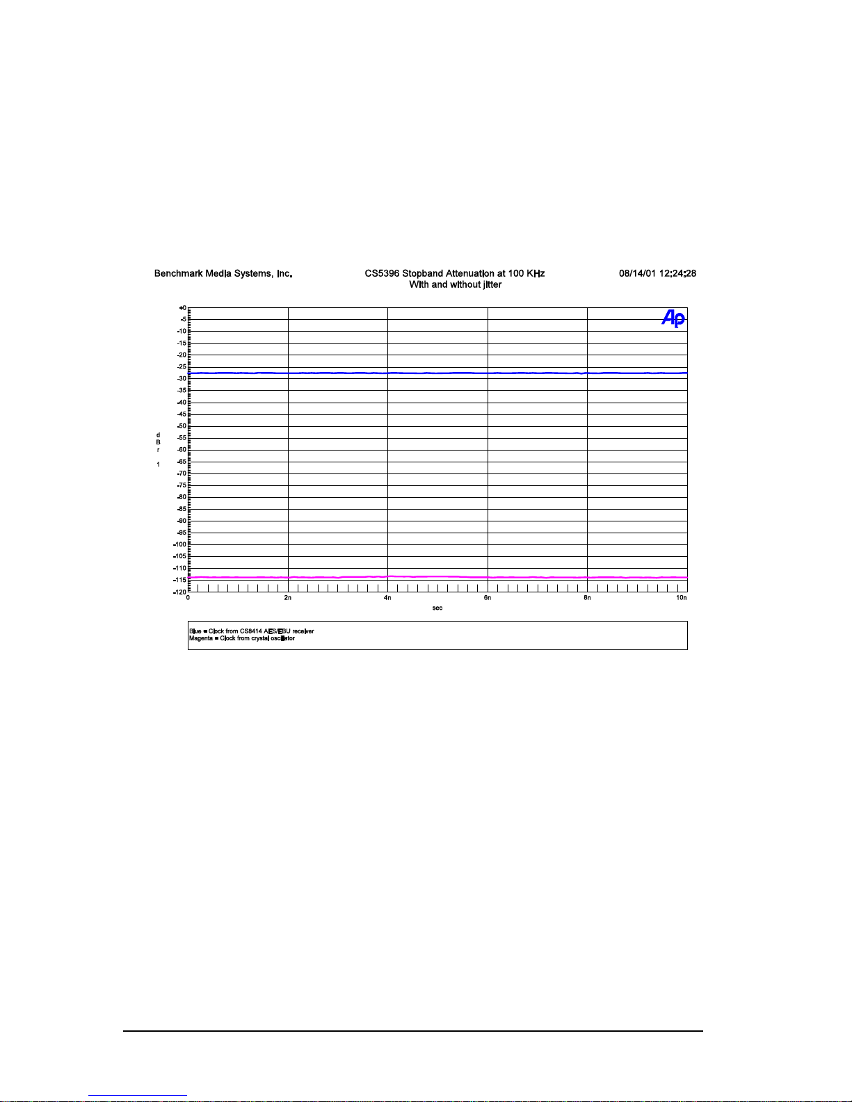
the response of the filter. For example, if converter clock in the AD2402-96 were derived
directly from the AES/EBU receiver (as it is in many converter products) the stopband
attenuation at 100 kHz would be degraded from 117 dB to only 28 dB. The 100 kHz signal
that should have been removed is now splattered all over the audio band (see graph).
FIGURE 5. 100 KHZ STOP BAND ATTENUATION VS. JITTER AT THE CONVERTER CHIP
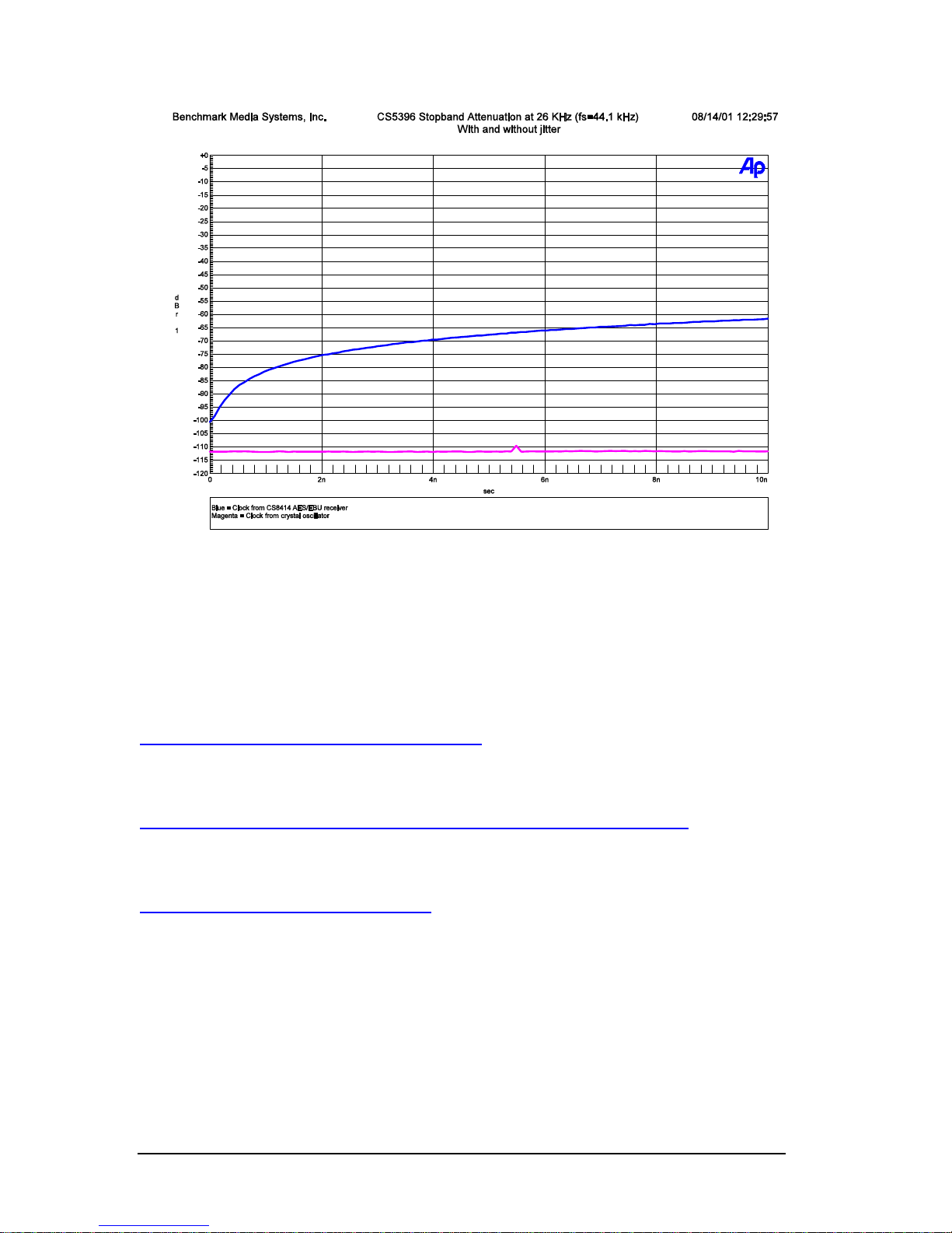
A second graph below shows the effect of jitter on the stop band attenuation with a 26-kHz
input signal.
33
Page 34
AD2402-96 - OPERATING MANUAL
FIGURE 6. 26 KHZ STOP BAND ATTENUATION VS. JITTER AT THE CONVERTER CHIP
Additional Information
Additional information about jitter may be found at the following locations.
http://www.nanophon.com/audio/jitter92.pdf
Jitter: Specification and Assessment in Digital Audio Equipment
rd
By Julian Dunn Presented at the 93
AES Convention – October 1992
http://www.audioprecision.com/publications/audiotst/jan96/jan961.shtml
Digital Audio Transmission: Why Jitter is Important
An Audio Precision Application Note By Dr, Richard Cabot
http://www.digido.com/jitteressay.html
Everything You Always Wanted To Know About Jitter But Were Afraid To Ask
By Bob Katz
34
Page 35

AD2402-96 - OPERATING MANUAL
Appendix
Word Length Reduction
The AD2402-96 is equipped with two state of the art world length reduction systems: The
Benchmark NN™ (Near Nyquist) system, and the Benchmark NS™ (Noise Shaped) system.
Unlike most competitive systems, the Benchmark NS™ system is based upon the most
current psycho-acoustic models. Furthermore, both Benchmark systems are unique in that
they were optimized while factoring in the noise contribution of the recording environment.
The Benchmark NN™ and NS™ word length reduction systems are the result of a
cooperative effort between Benchmark Media Systems, Inc., and the Audio Lab at the
University of Waterloo in Ontario Canada. We would especially like to thank Stanley P.
Lipshitz Ph.D., John Vanderkooy Ph.D., and Robert A. Wannamaker Ph.D. for their
pioneering research and for their significant contributions to the early stages of this project.
Special thanks are also in order to Robert Wannamaker for creating and modifying the
mathematical algorithms and filter coefficients which are at the core of the Benchmark
NN™ and NS™ systems.
We have taken a new approach by optimizing word length reduction for use in three
different levels of ambient noise. The ambient noise in a live recording situation is very
different from ambient noise level in a studio, and neither can be considered insignificant
when reducing 24-bit recording to 16-bits. All prior word-length-reduction systems ignored
the effects of this ambient noise and were optimized for noise-free input signals. The
Benchmark NN™ and NS™ systems were mathematically optimized while calculating the
effects of ambient noise. Three levels of input noise were used and three different curves
were produced. NN3™ and NS3™ represent optimal solutions where system noise is
limited only by the 24-bit A/D conversion process. NN2™ and NS2™ represent optimal
solutions where the ambient noise is 6 dB higher than the converter noise floor. NN1™
and NS1™ represent optimal solutions where the ambient noise is 12 dB higher than the
converter noise floor. When properly used, this optimization can improve the dynamic
range of a finished 16-bit recording by several decibels.
What is the Appropriate Setting to Use?
In general, NN3™ or NS3™ should be used for extremely low-noise studio recording
environments, NN2™ or NS2™ should be used for live recording, while NN1™ and
35
Page 36

AD2402-96 - OPERATING MANUAL
NS1™ should be reserved for noisy recording environments. The greatest possible dynamic
range will be achieved when the proper function is selected.
The choice of NN™ versus NS™ is mostly a matter of preference while the choice of
curves 1, 2 or 3 is largely dependent upon the dynamic range of the source material. Here are
a few general guidelines that should be followed:
1. If very high playback levels are anticipated, (i.e. playback gain will be high enough for the
noise floor to be heard), use the NN™ settings as these produce natural sounding noise
floors.
2. If the source material has been subjected to a prior 16-bit word length reduction process,
select NN3™ for subsequent processing.
3. If low to moderately high playback levels are anticipated (i.e. playback gain will be low
enough that the noise floor is inaudible), use the NS™ settings as these yield the greatest
dynamic range.
4. The NS™ functions can achieve lower psycho-acoustic noise levels than the
corresponding NN™ functions.
5. When in doubt concerning ambient noise levels, use a higher numbered function.
6. When in doubt concerning anticipated playback levels, use an NN™ function.
7. When totally in doubt, use NN3™ and then try other settings as you gain familiarity with
the system.
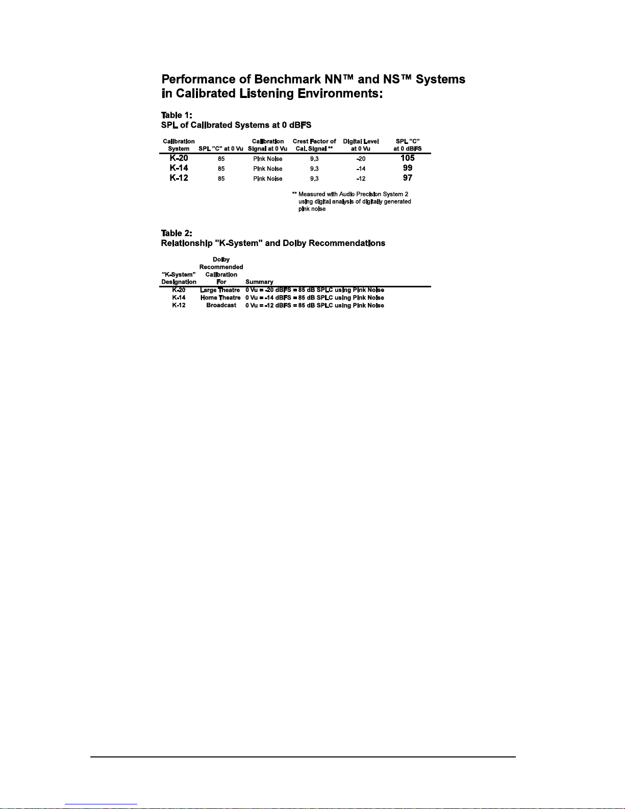
8. The mathematically inclined can use the charts in appendix 1 to calculate dynamic range,
and the audibility of the various NN™ and NS™ functions.
While each of the Benchmark NN™ and NS™ processes have been optimized for certain
levels of ambient noise contribution, it is important to point out that the processes do not
rely on this noise for dithering. TPDF dither is always applied to the 24-bit signal prior to
word length reduction. The NN™ and NS™ processes are always fully dithered to insure
full randomization of the quantization noise, and to insure that the quantization noise is decorrelated from the audio signal. Any of the NN™ and NS™ processes can be used on any
source without the risk of distortion that can result from an inadequate dither process.
Furthermore, the NN™ and NS™ processes can be used in cascade without any ill effects
other than a slight increase in the noise floor.
What Happens when NN™ or NS™ Processes are used in Cascade?
Every time the number of generations is doubled, the noise-floor will increase by 3 dB. For
example, two passes through a NN™ or NS™ process will reduce the dynamic range by 3
dB (as compared to the results obtained after only one pass). After 4 passes through a
NN™ or NS™ process, the dynamic range will have decreased by an additional 3 dB for a
total of 6 dB. And after the 8
dB. We have provided charts in appendix 1, which show the results of cascaded processes.
Please note that the noise of a first generation 16-bit process is at or slightly above the
threshold of audibility. Multiple passes through 16-bit word length reduction processes will
raise the noise floor above the threshold of audibility, and should therefore be avoided when
possible. If there is no alternative, and 16-bit word length reduction must be cascaded,
th
pass, the dynamic range will have decreased by a total of 9
36
Page 37

AD2402-96 - OPERATING MANUAL
NN3™ or NS3™ should be used for the first process, while NN3™ should be used for all
subsequent processing steps.
Why is NN3™ Recommended for Cascaded 16-bit Processes?
The NN™ processes produce a noise floor that sounds very much like white noise. On the
other hand, the NS™ processes produce a colored noise floor and are best suited for
applications where this noise floor is below the threshold of hearing. The advantage of
using a NS™ process is that the dither noise will remain inaudible at higher playback levels,
than if a corresponding NN™ process were used. IF the NS™ dither noise exceeds the
threshold of audibility (due to cascaded processing or very high playback levels), the NS™
process will yield better results. The reason for this is that the natural sound of white noise
is less distracting than colored noise even when the colored noise is at a slightly lower level.
Dither
Reducing a 20-bit or 24-bit audio to 16-bits always requires the addition of dither noise.
Failure to add a source of dither prior to each truncation process will create distortion in the
output. Remember that dither noise is of a very low level, and remains inaudible or nearly
inaudible until the gain of a playback system is made extremely high.
A good word length reduction system will remain inaudible during quiet portions of a
recording, even when the playback system is adjusted to achieve high peak sound pressure
levels. Dither that is audible will tend to mask musical details. This masking effect of dither
increases as the audibility of the dither increases.
While it is desirable to keep the dither inaudible, it is also necessary to apply enough dither to
fully randomize the noise added by word length reduction. The Benchmark NN™ and
NS™ systems provide full randomization and are carefully designed for minimum audibility.
Benchmark word length reduction systems never add distortion. They only add very lowlevel random noise. Unlike other noise reduction systems, this low-level noise is not effected
by the musical signal.
TPDF dither (white noise dither), will always be more audible than the dither noise
produced by a well-designed word length reduction system. The Benchmark 16-bit 44.1-kHz
NS3™ system yields a whopping 14-dB improvement over 16-bit TPDF. 16-bit 44.1 kHz
NS3™ will remain inaudible unless play back levels are adjusted such that a 0 dBFS signal
exceeds 107 dB SPL. In contrast, 16-bit TPDF dither will become audible when playback
levels are adjusted such that a 0 dBFS signal exceeds 93 dB SPL. Please note, at these gain
settings, the dither will only begin to be audible when there is a point of
full silence in the
recording, and then only when the room itself is also sufficiently quiet. Dither noise is never
audible in the presence of a 0 dBFS signal.
37
Page 38
AD2402-96 - OPERATING MANUAL
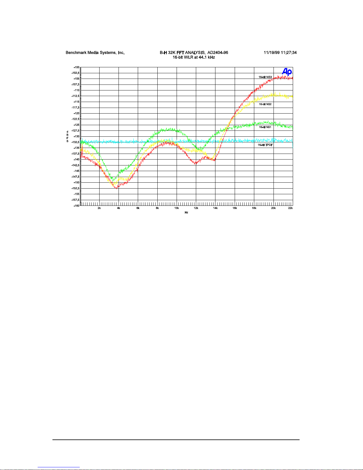
16-BIT NS™ WORD LENGTH REDUCTION CURVES FOR 44.1 KHZ
The 16-bit 44.1-kHz NS3™ noise shaping, shown above, provides a 14-dB improvement
over 16-bit TPDF, in terms of noise audibility. (See table on page 28)
38
Page 39
AD2402-96 - OPERATING MANUAL
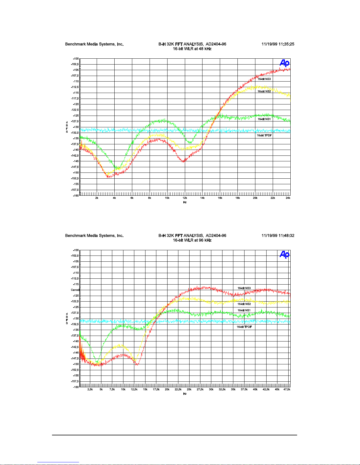
16-BIT NS™ WORD LENGTH REDUCTION CURVES FOR 48 KHZ
The 16-bit, 48-kHz NS3™ has a 17-dB advantage over 16-bit TPDF.
16-BIT NS™ WORD LENGTH REDUCTION CURVES FOR 96 KHZ
The 16-bit, 96-kHz NS3™ provides a 28-dB improvement over 16-bit TPDF.
39
Page 40

AD2402-96 - OPERATING MANUAL
Will Dither Noise Damage My Speakers?
Please note that nothing bad happens when the gain of a playback system is increased
enough to hear dither noise. Dither will not blow out your speakers, unless possibly
someone inadvertently turns on an audio source while the amplifier is in this high gain state!
Remember that dither is an extremely low-level signal (much like tape hiss, only of a much
lower level).
How is the Performance of a Word Length Reduction System
Measured?
The audibility of dither can be expressed in terms of "F-Weighted Noise Power". The Fweighting function is derived from measurements of the ear's sensitivity to very low level
signals. At 16-bits, 44.1-kHz the F-weighted noise power of TPDF dither is -93.3 dBFS and
the F-weighted noise power of NS3™ is -107.5 dBFS. In other words, 16-bit TPDF dither
provides a 93.3 dB noise-free dynamic range, while NS3™ provides a much greater 107.5 dB
noise-free dynamic range.
All word length reduction systems add noise to the audio, it is a law of mathematics.
However, the noise can be placed anywhere within the bandwidth of the digital system. If
the noise is evenly spread out over the entire bandwidth (as it is with TPDF dither), the
system will yield the lowest possible unweighted noise when measured on an audio analyzer.
But, a uniform noise distribution is not the best solution from an audibility standpoint. Our
ears are not equally sensitive to all frequencies within the 0 to 22.05 kHz bandwidth of a 44.1
kHz digital system. The audibility of the added noise is greatly reduced when it is
concentrated at frequencies where our ears are least sensitive. Near-Nyquist systems reduce
noise audibility by concentrating most of the noise energy between 18 kHz and the Nyquist
frequency (1/2 of the sample rate) while maintaining a relatively flat and natural sounding
noise floor below 16 kHz. Noise-Shaped systems attempt to achieve the greatest possible
noise improvement by distributing the noise in a function that is the inverse of the ear’s
sensitivity. TPDF will read the lowest on the meters, but will always sound louder than a
good word-length-reduction system. Don’t let the meters fool you! Remember, most
meters “hear” equally well at all frequencies.
Avoid Truncation without Dither:
There are numerous potential sources of noise within an A/D converter. These may include
thermal noise, noise from a delta sigma modulation process, cross talk, clock feed-through,
etc. None of these sources of noise are added intentionally, but in many cases these noise
sources may be of a high enough level to allow truncation without the addition of a dither
signal. For example, many 20-bit A/D converters have enough self-noise to allow their
outputs to be truncated to 16-bits without ill effects. Similarly many 24-bit converters have
enough self-noise to allow truncation to 20-bits. Many recording engineers have discovered
that they can truncate the outputs of their A/D converters without causing distortion. Do
not try this with the AD2402-96! The AD2402-96 is a
very quiet 24-bit converter, and it
40
Page 41

AD2402-96 - OPERATING MANUAL
does not have enough self-noise to provide adequate dither for truncation to 20-bits (nor 16bits). For this reason it is imperative to use one of the 20-bit output settings when feeding
20-bit devices, and one of the 16-bit settings when feeding 16-bit devices. Remember that
truncation without adequate dither will cause distortion.
One additional caution concerning truncation: Each world length reduction process requires
a new source of dither noise. For example, consider a signal starts out at 24-bits and is
dithered down 16-bits. Lets suppose we take this 16-bit signal and feed it into a 24-bit digital
audio workstation, and apply a minor gain change or a touch of EQ. This 16-bit signal has
now become a 24-bit signal inside the workstation. If the final product is going to be 16bits, a second 24 to 16-bit word length reduction process must be applied. Some have
assumed that it is not necessary to add dither in the second process because it was already
added in the first process. However, truncation to 16-bits at the output of the workstation
will add distortion to the audio. Instead, use the digital to digital word length reduction
feature in the AD2402-96 to reduce the word length back to 16-bits. Remember every word
length reduction process requires a new source of dither noise.
Digital Word Length Increases when a Signal is Processed:
Every time a digital signal is processed, its word length increases. "Processing" includes even
simple operations such as level changes and the mixing of two signals. Word lengths expand
dramatically when more complex operations such as equalization, sample rate conversion,
and effects processing are applied. Long word lengths created by digital signal processing
must be shortened before they can be re-recorded or sent to a DAC for monitoring.
Every time a digital word length is shortened, a new source of noise must be added to the
signal prior to truncation. Dither noise that was applied for one truncation operation is not
useful for dithering a subsequent truncation operation. Failure to add a new source of noise
prior to each truncation process will create distortion. The self-noise of an A/D converter,
the noise of the mic-pre, and ambient noise. Again, every word length reduction process
requires a new source of dither noise.
Additional Information
An article on dither and a web audio demonstration by Christopher M. Hicks of the effects
of three forms of word length reduction can be found at
http://www.mtsu.edu/~dsmitche/rim420/reading/rim420_Dither.html
Demonstrated are; rounding, TPDF dither and simple noise shaped dither. This is an
excellent and graphic demonstration of these issues.
Another educational overview of digital audio and dither by Christopher M. Hicks may be
accessed at http://www.benchmarkmedia.com/appnotes-d/hicks1994.htm A more in depth
educational paper by Mr. Hicks in PDF form is found at
http://www.benchmarkmedia.com/appnotes-d/ditherap.pdf
41
Page 42

AD2402-96 - OPERATING MANUAL
Another dither article entitled "The Secrets of Dither" authored by Bob Katz, can be found
at http://www.digido.com/ditheressay.html
42
Page 43
AD2402-96 - OPERATING MANUAL
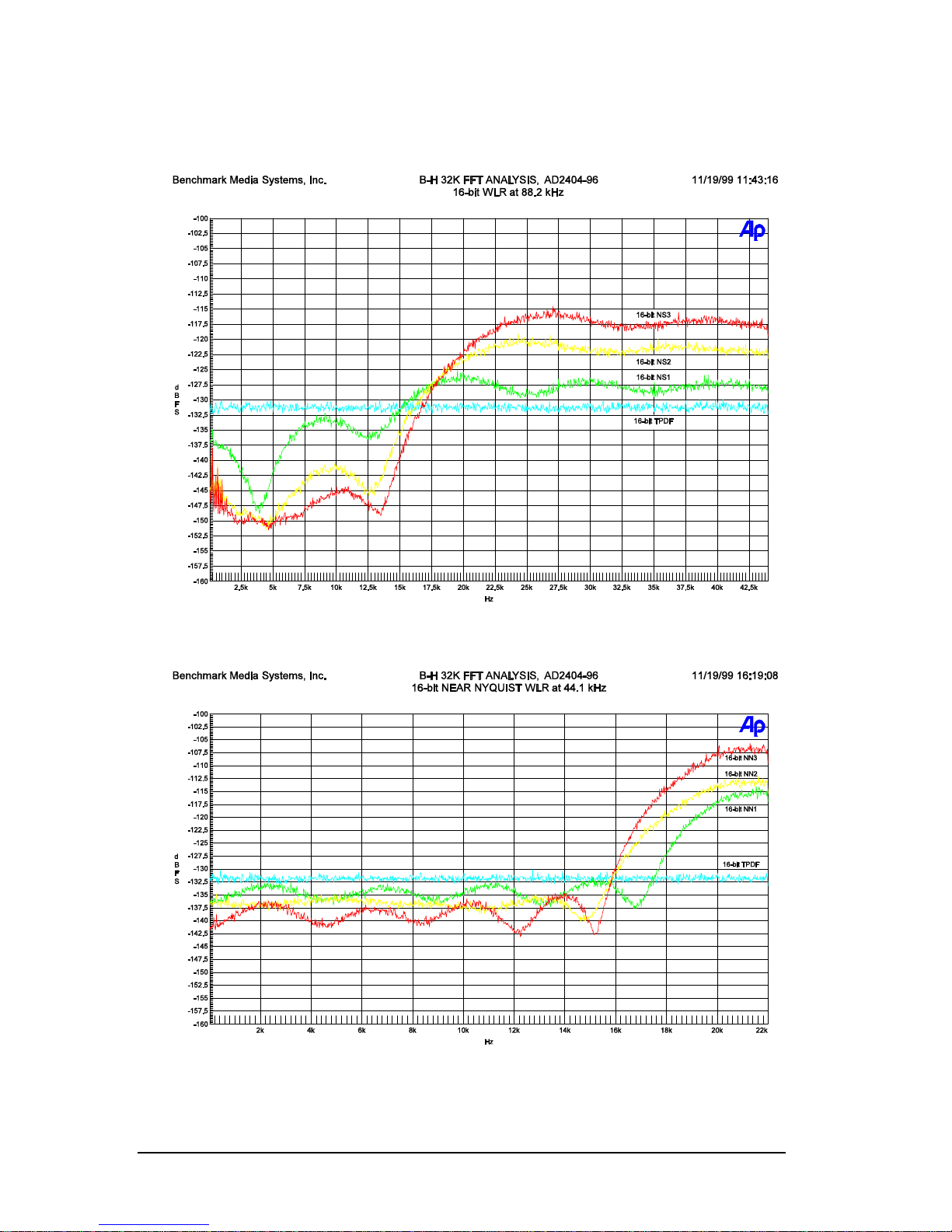
Additional Word Length Reduction Curves
16-BIT NS™ WORD LENGTH REDUCTION CURVES FOR 88.2 KHZ
16-
BIT NN™ WORD LENGTH REDUCTION CURVES FOR 44.1 KHZ
43
Page 44
AD2402-96 - OPERATING MANUAL
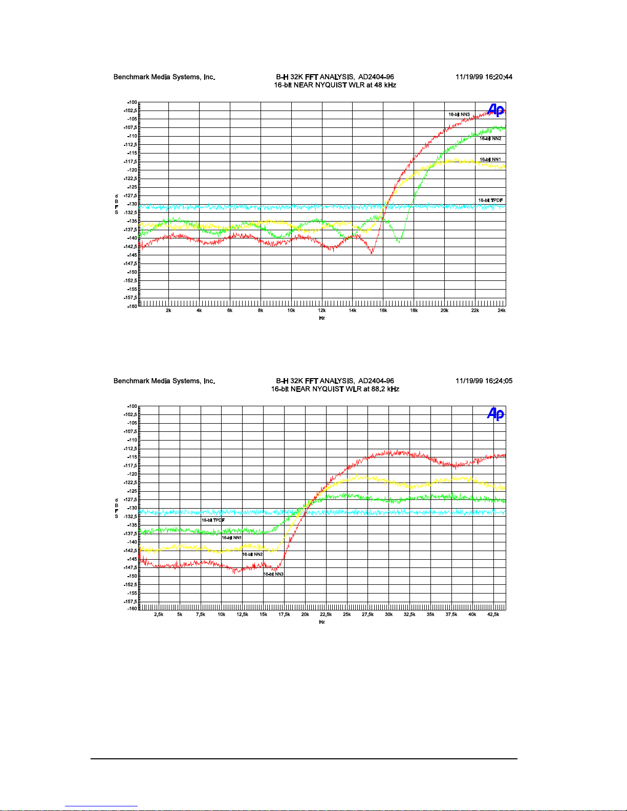
BIT NN™ WORD LENGTH REDUCTION CURVES FOR 48 KHZ
16-
16-
BIT NN™ WORD LENGTH REDUCTION CURVES FOR 88.2 KHZ
44
Page 45
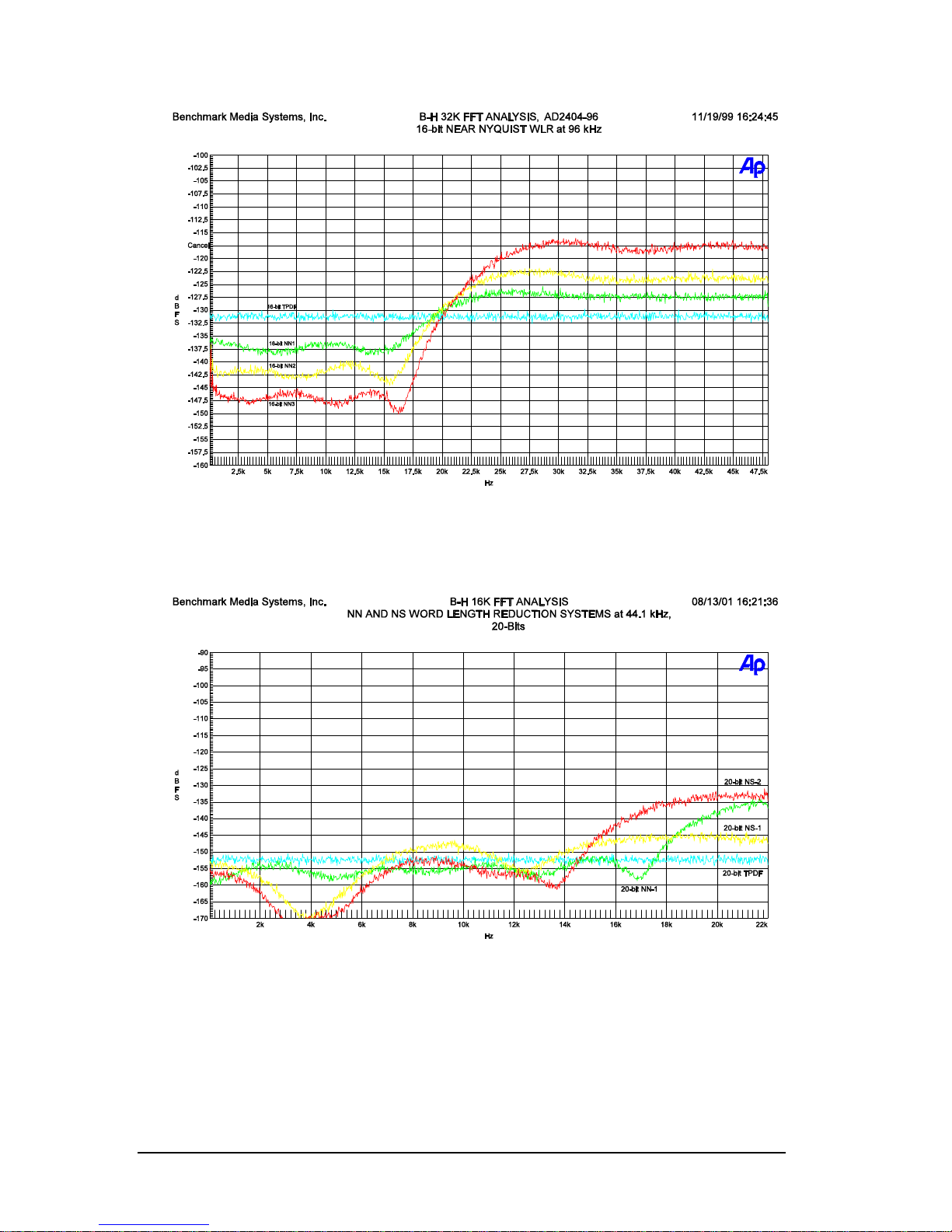
AD2402-96 - OPERATING MANUAL
16-
BIT NN™ WORD LENGTH REDUCTION CURVES FOR 96 KHZ
20-
BIT WORD LENGTH REDUCTION CURVES FOR 44.1 KHZ
45
Page 46
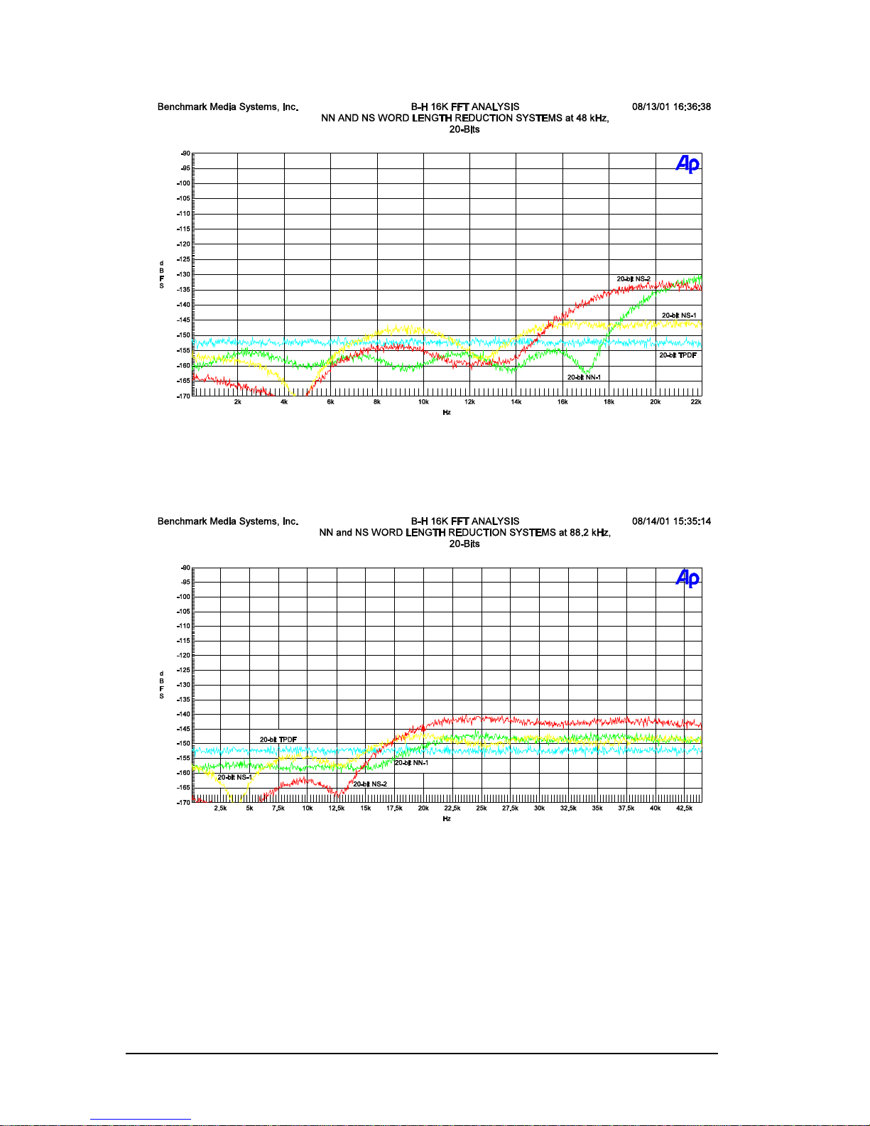
AD2402-96 - OPERATING MANUAL
20-
BIT WORD LENGTH REDUCTION CURVES FOR 48 KHZ
20-
BIT WORD LENGTH REDUCTION CURVES FOR 88.2 KHZ
46
Page 47
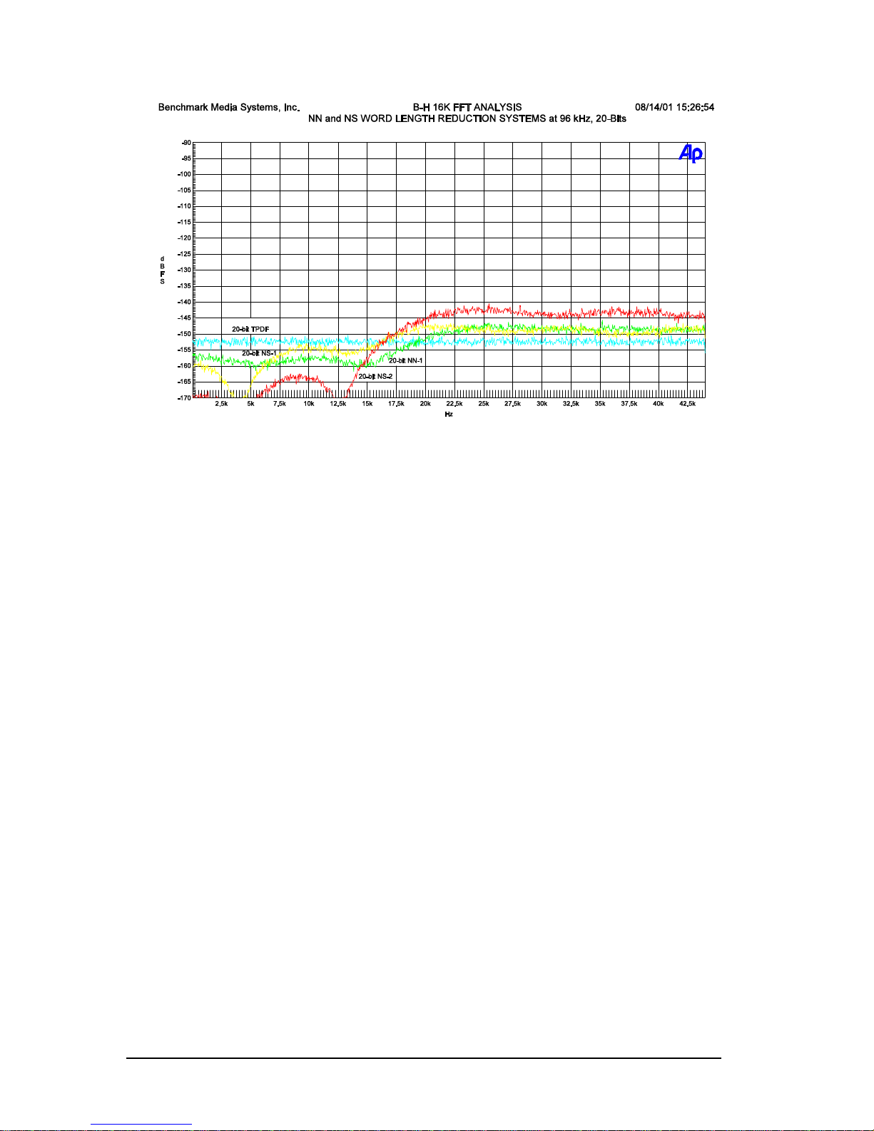
AD2402-96 - OPERATING MANUAL
20-
BIT WORD LENGTH REDUCTION CURVES FOR 96 KHZ
47
Page 48

AD2402-96 - OPERATING MANUAL
Compliance and SAFETY
INFORMA TION for the
AD2402-96 A-to-D Conv erter
FCC Class B Compliance
This device complies with part 15 of the FCC Rules. Operation is subject to the following two conditions:
(1) This device may not cause harmful interference, and
(2) This device must accept any interference received, including interference that may cause undesired
operation.
Safety Information
Do NOT service or repair this product unless properly qualified. Only a qualified technician or authorized
Benchmark Media Systems, Inc. distributor should perform servicing.
For continued fire hazard protection, fuses should be replaced ONLY with the exact value and type as
indicated on the rear panel and on this page below.
Do NOT substitute parts or make any modifications without the written approval of Benchmark Media
Systems, Inc. Doing so may create safety hazards.
This completes the AD2402-96 operation manual. Ed. November 9, 2004
48
 Loading...