

Page 1
TM
benchmark
The code of practice for the installation,
commissioning & servicing of centralheating systems
2000
2000
ACCOLADE
ACCOLADE
DESIGN, INSTALLATION AND
SERVICING INSTRUCTIONS
PLEASE LEAVE THESE INSTRUCTIONS IN THE POCKET PROVIDED ON
THE BACK OF THE FRONT PANEL
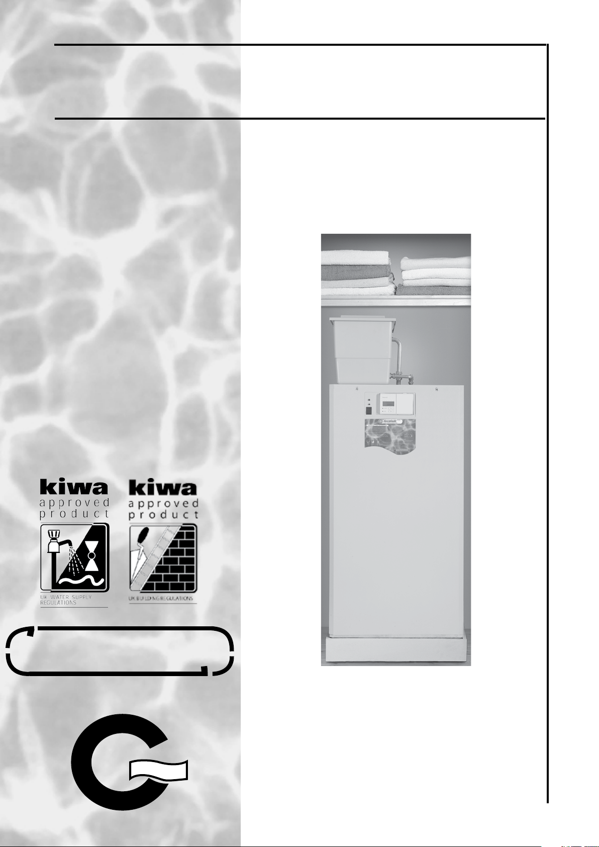
An unvented hot water storage unit complying with the
requirements of Building Regulations Approved Document G3.
Please read these instructions before commencing
installation and on completion leave adjacent in the pocket on
the back of the appliance front panel.
In the interest of continuously improving the Accolade
Gledhill Water Storage Ltd reserve the right to modify the product
without notice, and in these circumstances this booklet, which is
accurate at the time of printing, should be disregarded.
2000
range,
Page 2
TM
benchmark
The code of practice for the installation,
commissioning & servicing of centralheating systems
ISSUE 2: 06-08
Section Page
1.0 DESIGN
1.1 Introduction
1.2 Technical Data
1.3 System Details
2.0 INSTALLATION
2.1 Site Requirements
2.2 Installation
2.3 Commissioning
3.0 SERVICING
3.1 Annual Servicing
3.2 Changing Components
As part of the industry wide “Benchmark” Initiative all Gledhill Accolades now include
a Benchmark Installation, Commissioning and Service Record Log Book. Please read
carefully and complete all sections relevant to the appliance installation. The details
of the Log Book will be required in the event of any warranty work being required.
There is also a section to be completed after each regular service visit. The completed
Log Book and these instructions should be left in the pocket provided on the
back of the front panel.
3.3 Short Parts List
3.4 Fault Finding
Appendix ‘A’
Appendix ‘B’
Terms & Conditions
Page 2
Page 3
1.0 DESIGN
1.1 INTRODUCTION
The Acco lade
directly and indirectly heated unvented hot
water storage app lian ces is de sign ed to
provide domestic hot water at mains pressure.
The direct models are fitted with two 3kW
immersion heaters and are designed for electric
hot water heating only. The indirect models are
designed for gas or oil fired heating and hot
water systems with boiler capacities up to a
maximum of 45kW. All indirect models are
fitted with a 3kW immersion heater for heating
domestic hot water in the event the boiler
fails. The Accolade
fitted with all the necessary safety and control
equipment for connecting it to the cold water
mains, boiler and heating system.
These instructions cover all the models and
must be followed. Thes e applian ces have
been certified for safety and therefore it is
important that these instructions are followed.
The appliance and installation specifications
of the appliances must not be modified unless
recommended by Gled hil l Water Storage
Limited.
SAFETY
1.The B u i l ding R e gulations ( Approved
Document G3) 2002 cover the installation of
unvented storage water heating equipment
and these require that the installation of an
unvented unit shall only be carried out by
a person competent to do so (as defined in
the Approved Document) and that the Local
Authority shall be notified of the intention
to carry out the installation of one of these
types of appliances.
200 0
range of flo or stand ing
2000
appliances are factory
Page 3
2.The system must be installed in accordance
wit h t he W a t er S u ppl y R eg u lat i o ns,
Building Regulations and relevant NHBC
requirements.
3. As the Accola d e 20 0 0 is an unven ted
appliance it should not be used where
steam is the primary heating medium, or
with solid fuel boilers, or in situations where
annual inspection/maintenance is likely to be
neglected.
2000
ACCOLADE
Page 4
1.0 DESIGN
1.1 INTRODUCTION
BS 5440 Pts. 1 & 2; BS 5449; BS 5546; BS 7074
Part 1; BS 6700; BS 6798; BS 6891, BS 7593,
IGE/UP/7/1998
3. Equipment Selection
This information is provided to assist generally
in the selection of equipment. Responsibility
for selection and specification of our equipment
must, however, remain that of our customers
and any expert or consultants concerned with
the installations).
Please note: -
We do not accept any responsibility for
matters of design selection or specification
or the effec tiveness of an installation
containing one of our products unless
specifically asked in writing to do so.
IMPORTANT NOTICES
1. Handling and Storing the Appliance
This appliance should be handled carefully to avoid damage and the recommended
method is detailed below.
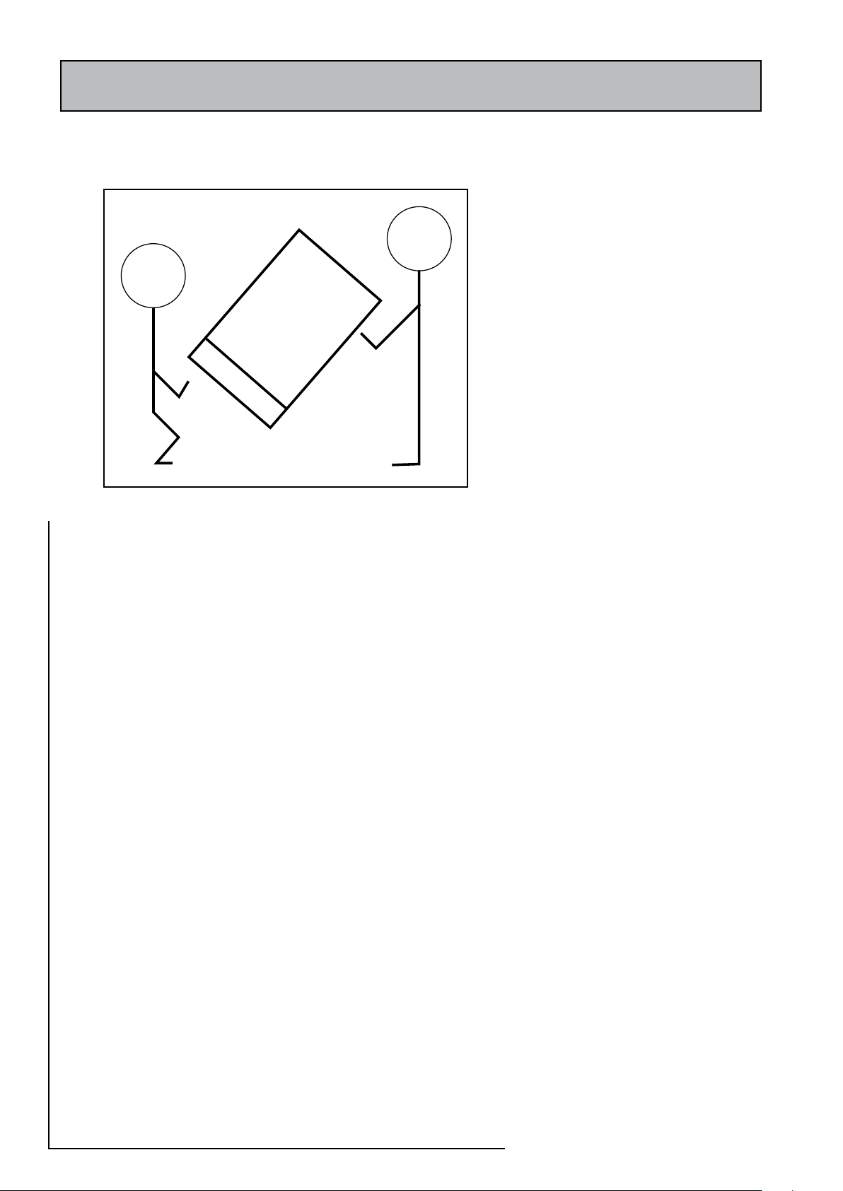
When lifting the unit:-
• Use a team lift
• Work with someone of similar build and height if possible.
• Choose one person to call the signals
• Lift from the hips at the same time, and then raise the unit to the desired level.
• Move smoothly in unison.
The appliance is supplied shrink wrapped on a timber installation base. Carrying
handles are provided towards the top of the left hand side of the casing and at the
bottom of the opposite side.
If the unit needs to be stored prior to installation it should be stored upright in a dry
environment and on a level base/floor.
Note: Although the above guidance is provided any manual handling/lifting
operations will need to comply with the requirements of the Manual Handling
Operations Regulations issued by the H.S.E.
The appliance can be moved using a sack truck on the left hand face although care
should be taken and the route should be even. In apartment buildings containing a
number of storeys we would recommend that the appliances are moved vertically
in a mechanical lift. If it is proposed to use a crane expert advice should be obtained
regarding the need for slings, lifting beams etc.
2. System Installation
Any installation must be in accordance with the relevant requirements of the
current issue of Local Building Regulations, the Water Supply Regulations, Health &
Safety Document No. 635 and the Electricity at Work Regulations 1989. The detailed
recommendations are contained in the current issue of the following British Standards
and Codes of Practices: -
All goods are sold subject to our Conditions
of Sale which are set out in the Appendix
to this document.
Warning
To comply with the Building Regulations
requi reme nts thi s appli ance must be
ser viced and installed by a competent
person suitably trained and registered
to in s t all u nvented heati n g sys t e m
equipment.
As part of the industry wide ‘Benchmark’
initiative all Accolade 2000 appliances
now include a Benchmark Installation,
Co mmission i n g and Ser vice R e c o r d
Logbook. Please read this carefully and
complete all secti ons relevant to this
appliance. Failure to do so may affect
warranty.
Modifi cat ions should NOT be mad e
to this product . If any co mponents
in this applia nce are replaced and recommissioned in the field then these must
be obtained from Gledhill Water Storage
Ltd to ensure continued safe operation and
must not be tempered with. This applies
particularly to the immersion heaters which
must incorporate an overheat thermostat.
Page 4
Page 5
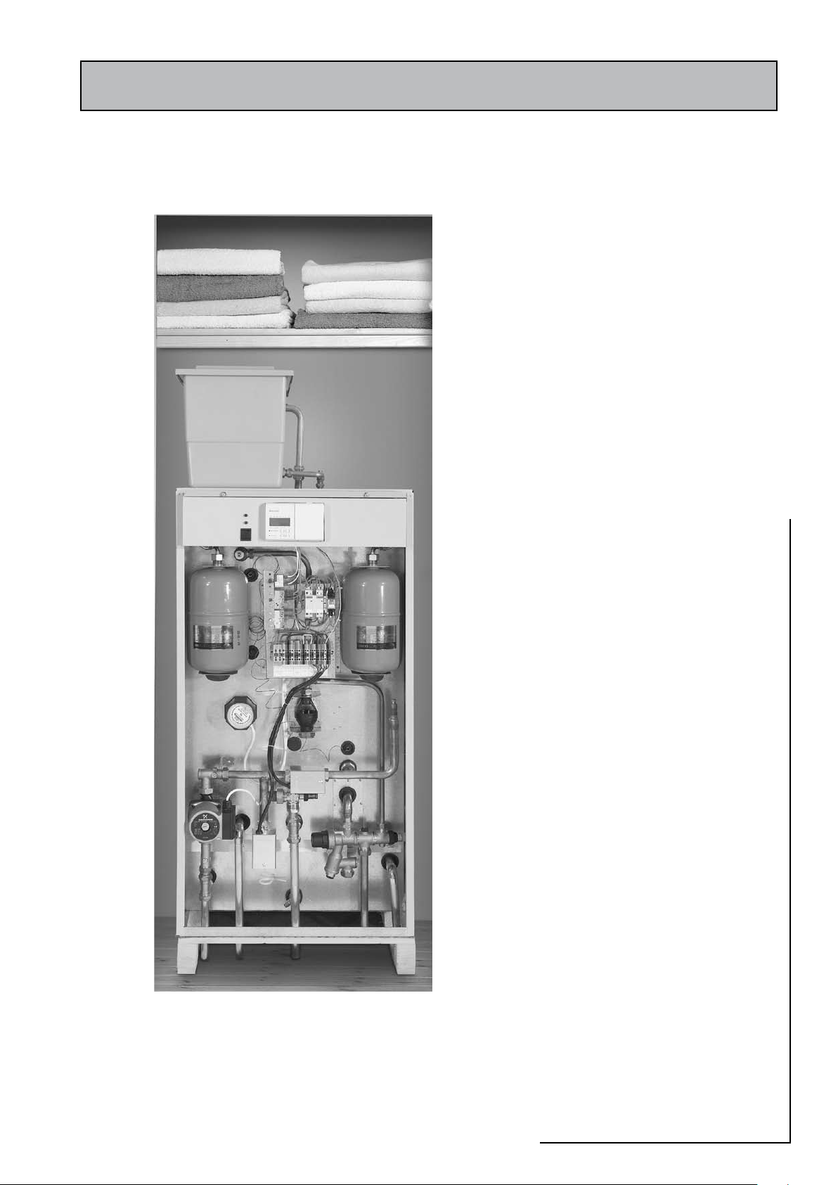
1.0 DESIGN
1. 1 INTRODUCTION
Description
The Accolade 2000 is a floor standing packaged
mains pressure unvented hot water appliance
and uses a twin copper cylinder configuration
which ensures that all the water content is
heated to a uniform temperature as well as
reducing the risk of legionella and corrosion.
All cylinders are manufactured in accordance
with the requirement of BS7206:1990. All
models of the Accolade are factory fitted with
all the necessary safety and control equipment
for connecting it to the domestic water systems,
the boiler and the heating system (see table
1.1).
The indirect models shown in figure 1.1 are
designed to be heated indirectly by a gas or oil
fired boiler and are available for use with both
open vented and sealed heating systems. These
appliances are also fitted with a 3kW immersion
heater for heating the hot water in the event
of a boiler failure. The immersion heater is
factory wired into the appliance control panel
and does not require a separate electricity
wiring supply.
The direct models shown in figure 1.2 are
fitted with two 3kW immersion heaters and
are designed for electric hot water heating
only usually utilizing off peak electricity.
Models AC180_ID, AC210_ID, AC175_D and
AC210_D are fitted with a secondary return
tapping as standard. If secondary hot water
circulation is installed, then an additional
expansion vessel may be necessary. Typical
primary hot water circulation system design is
discussed further in section 3 of this manual.
Page 5
2000
ACCOLADE
Page 6
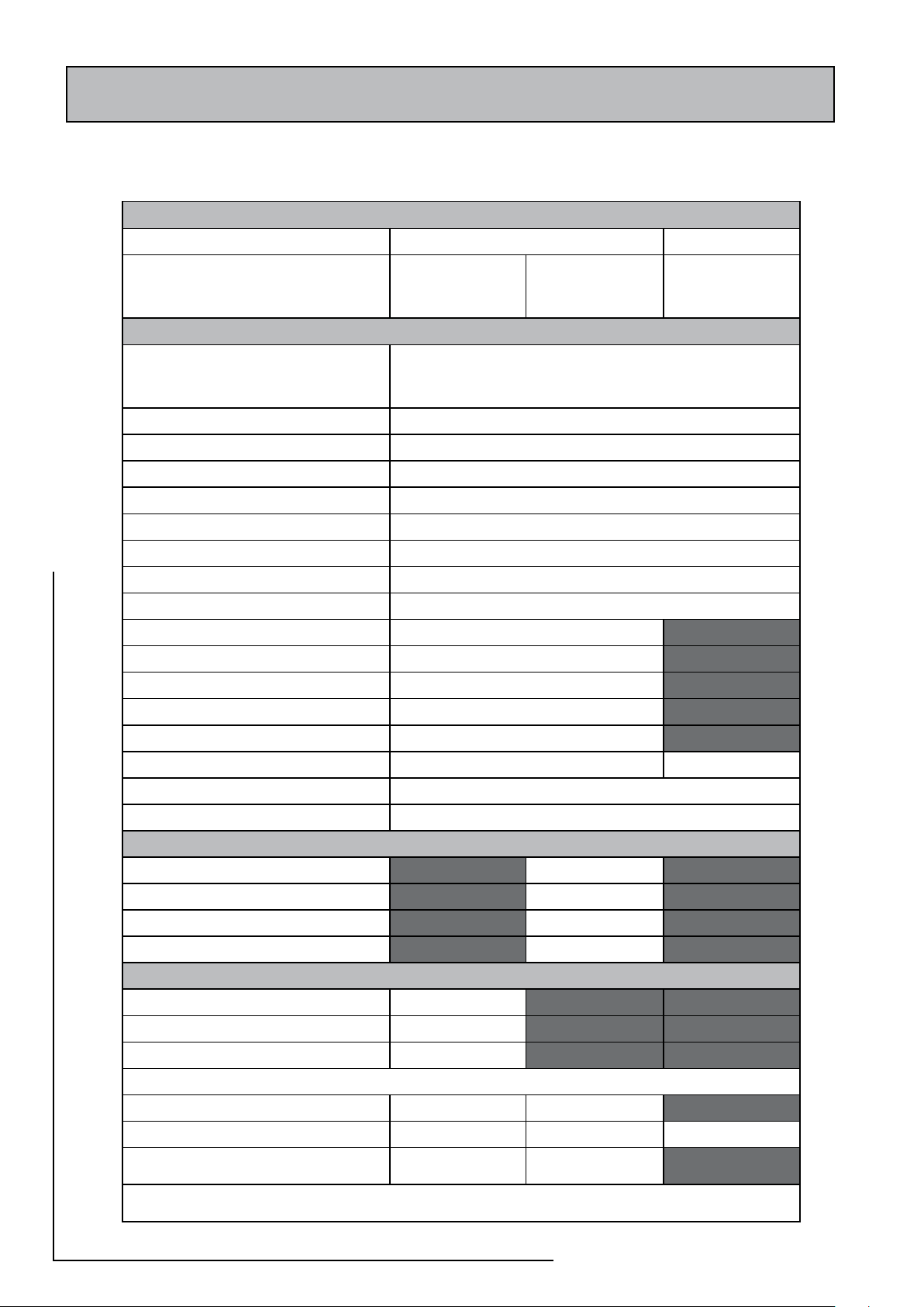
stnenopmocdeilppusdnadettifyrotcaF1.1elbaT
sledoMtceridnI sledoMtceriD
VO_DI_521CA
VO_DI_051CA
VO_DI_081CA
VO_DI_012CA
SS_DI_521CA
SS_DI_051CA
SS_DI_081CA
SS_DI_012CA
D_041CA
D_571CA
D_012CA
tnempiuqedradnatsderiwdnadettifyrotcaF
fognitsisnocpuorglortnoctelnierusserpsniaM.1
,reniartS,rotalugererusserP,evlavnruter-noN
retawdlocdecnalabdnaevlavfeilernoisnapxE
teltuo
rab5.1-erusserpgnitarepotesyrotcafelbatsujdanoN-seY
evlavfeiler)T&P(erutarepmeTdnaerusserP.2 serusserpgnitarepotesyrotcafelbatsujda-noN-seY
hsidnuT.3 seY
tatsomrehtytefaS.4 resuotelbisseccatondnaelbatsujdanon,teserlaunam-seY
tatsomrehttimilhgiH.5 resuotelbisseccatondnaelbatsujdanon,teserlaunam-seY
tatsomrehtlortnoC.6 resuotelbisseccaton,elbatsujdA,seY
evlavmuucav-itnA.7 seY
ertnecgniriW.8 seY
)s(lessevnoisnapxeretawtohcitsemoD.9 seY
evlavenozretawtoH.01 seY
evlavenozgnitaehecapS.11 seY
pmupmetsyS.21 seY
evlavssapybcitamotuA.31 seY
remmargorp)retawtohdnagnitaeh(lennahC2.41 seY
statsomrehthtiwretaehnoisremmiWk3.51 eruliafreliobfoesacnipukcabrof(ffo1-seY ffo-2,seY
evlavmuucav-itnA.61
kcocniarD.71 seY
sledomSShtiwnoitallatsnietisnorofdradnatssadeilppus-tiKmetsySdelaeS
eguagerusserP.1 seY
lessevnoisnapxetiucric)gnitaeh(yramirP.2 seY
poolgnilliF.3 seY
evlavfeilernoisnapxE.4 seY
sledomVOhtiwnoitallatsnietisnorofdradnatssadeilppus-tiKdetneVnepO
dilhtiwnretsicnoisnapxEdnadeeF.5 seY
taolfdnaevlavllaB.6 seY
srotcennocknatdeefdlocdnawolfrevO.7 seY
redrofoemittadetseuqerebot-sartxElanoitpO
0636TllewyenoH-tatsomrehtmooR seY seY
tiknoitcennocelbixelF seY seY seY
pmup06/51SPUsofdnurG
seY
)ylno081&521(
seY
)ylno081&521(
ylnosmetsysgnitaehdetnevneporofelbatiusecnailppametsyS:VO-DI
smetsysgnitaehdelaeshtiwesuroftikhtiwdeilppusecnailppametsyS:SS-DI
1.0 DESIGN
1.2 TECHNICAL DATA
Page 6
Page 7

Indirect model photo
Figure 1.1
1.0 DESIGN
1.2 TECHNICAL DATA
Direct model photo - T.B.A. when available
Figure 1.2
2000
ACCOLADE
Page 7
Page 8
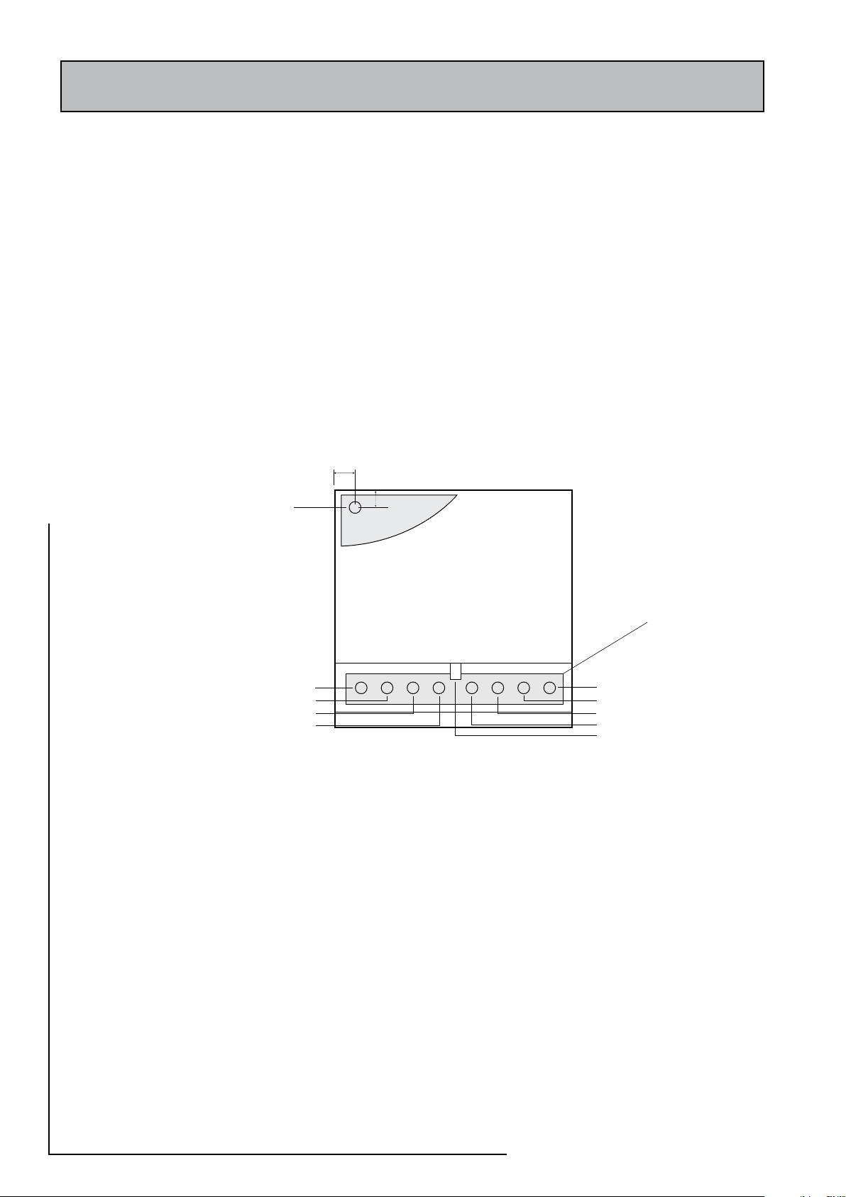
Model Selection Guide
Top
Bottom
Boiler Flow
Boiler Return
Heating Flow
Heating Return
Hot Outlet
Discharge Pipe
Balanced Cold Outlet
Cold Inlet
Drain Cock
Primary Expansion
(SS Model)
Combined Safety/Open Vent &
Cold Feed/Expansion
(OV Model)
Cut out area through
base of unit
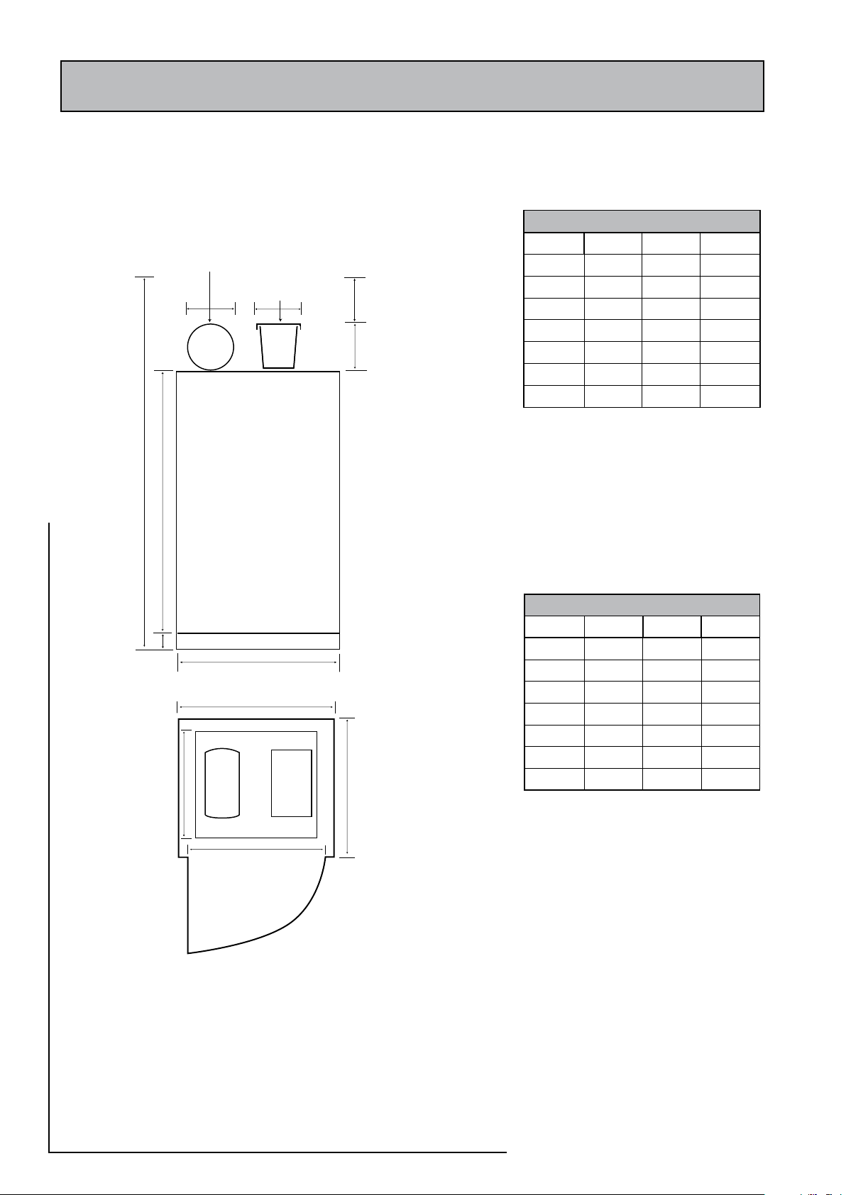
General selection criterion is shown in Technical Data table 2.1. However, before
selecting the model, the hot water requirements of the dwelling should be correctly
assessed. If the appliance is to be installed in a cupboard, then the minimum
dimensions and clearances specified in figure 1.4 must be observed.
Appliance Location
The Accolade must be installed on a flat surface, which is capable of supporting the
weight of the appliance and any other ancillary equipment.
The minimum airing cupboard dimensions and the clearances required for installation
and service are shown in figure 1.3.
The appliance is designed to be installed on the plinth supplied with the appliance.
The pipe connection arrangements for the direct and the indirect models are shown
in figures 1.4 and 1.5.
1.0 DESIGN
1. 2 TECHNICAL DATA
Figure 1.4 Connection Arrangement - Indirect
Figure 1.5 Connection Arrangement - Direct
Page 8
Page 9
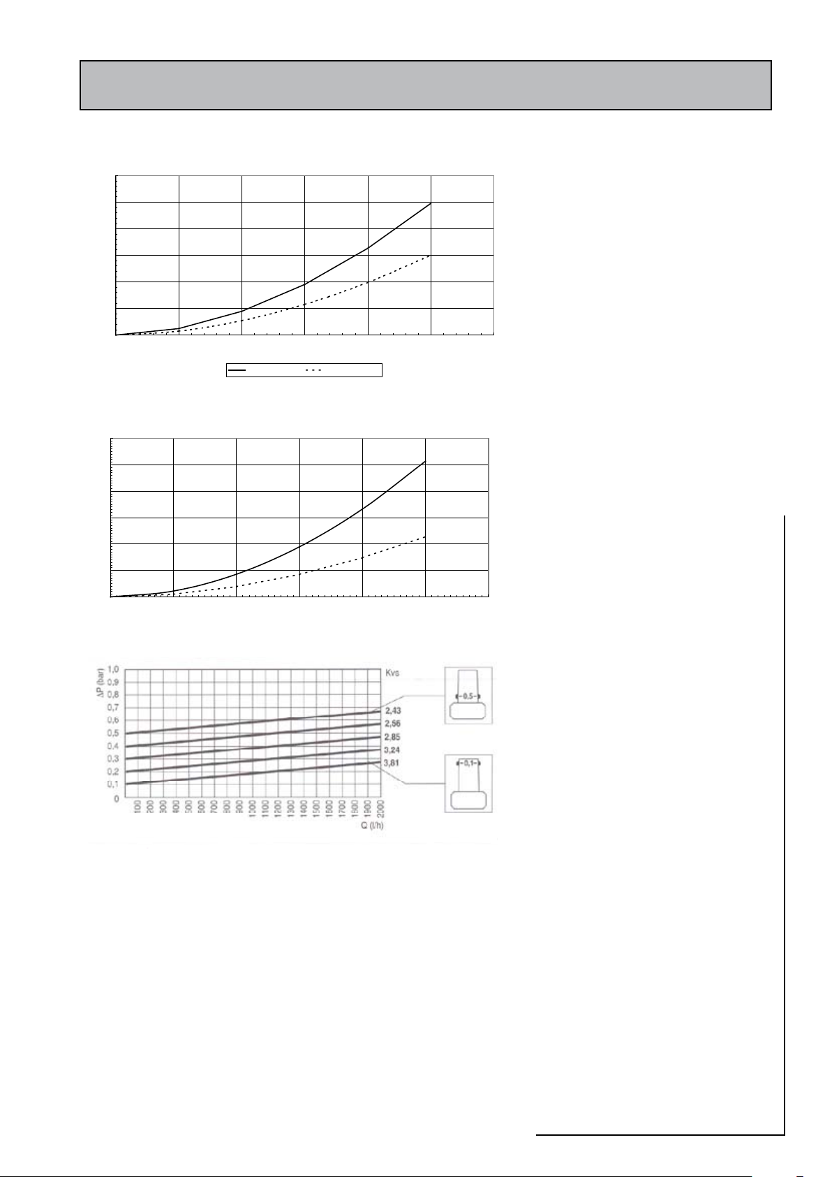
Primary heat exchanger (i.e. coil) pressure loss of Accolade 2000 Models
0
1
2
3
4
5
6
0 10 20 30 40 50 60
Primary heat exchanger circuit flow rate (l/min)
Pressure loss (m.W.G.)
AC125/AC150 AC180/AC210
Heating circuit pressure loss of Accolade 2000 Models
0
1
2
3
4
5
6
0 10 20 30 40 50 60
Heating circuit flow rate (l/min)
Pressure loss (m.W.G)
1.0 DESIGN
1.2 TECHNICAL DATA
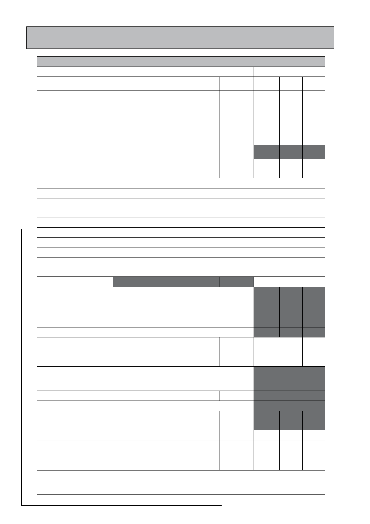
a. General technical and performance data of
the Accolade 2000 range is given in table
2.1.
b. The indirect models are fitted with high
performance primary heat exchangers and
are supplied with either Grundfos UPS 15-50
or UPS 15-60 factory fitted pumps. The net
pump head available when hot water only
is on and when space heating only is on is
shown in figures 1.6 and 1.7 respectively.
The control characteristic of the automatic
bypass is shown in figure 1.8.
Figure 1.6 Net pump head available - Hot water only on
Figure1.7 Net pump head available - Heating only on
c. In these appliances the mains inlet pressure
regulating valve is set to 1.5 bar and this
setting MUST NOT be adjusted. Therefore
the flow rate from the appliance depends
upon the resistance of the hot water supply
network, capacity of the incoming mains and
the characteristics of the pressure regulating
valve. Typic al hot water flow rates for
different pressures are shown in figure 1.9.
Figure 1.8 Automatic bypass valve characteristics
Figure 1.9 Hot water flow rates from Accolade 2000
2000
ACCOLADE
Page 9
Page 10
or
or
A
F
100mm
B
D
E
C
350mm min.
min. door opening
605mm
Primary expansion
vessel
Feed & expansion
circuit
snoisnemiDecnailppA
ledoM )A(thgieH )B(htdiW )C(htpeD
DI021 0411 595 595
DI051 0731 " "
DI081 0061 " "
DI012 0591 " "
D041 0731 " "
D571 0061 " "
D012 0591 " "
snoisnemiDdraobpuCmuminiM
ledoM )F(thgieH )D(htdiW )E(htpeD
DI021 0981 007 006
DI051 0212 " "
DI081 0532 " "
DI012 0072 " "
D041 0031 " "
D571 0571 " "
D012 0012 " "
1.0 DESIGN
1. 2 TECHNICAL DATA
Note: The appliance dimensions do not allow
for the 100mm base.
Figure 1.3 Minimum cupboard dimensions
The table of minimum cupboard dimensions
only allow the minimum space required for
the appliance (including the F & E cistern and
expansion vessel) and any extra space required
for shelving etc in the case of airing cupboards
etc must be added.
The dimensions above are for the OV model and
based on the appliance and the F & E cistern
being in the same cupboard.
For the SS model 300 mm can be deducted
from the height.
Page 10
Page 11

1.0 DESIGN
1. 2 TECHNICAL DATA
Electricity Supply
Only one mains supply rated at 16A, 230V~,
50Hz is required for the indirect models.
All indirect models have a 3kW electric
immersion heater for hot water backup in
case of boiler failure. The immersion heater
and boiler circuits are fused internally.
The direct models have two 3kW immersion
heaters and therefore require two (usually
one on-peak and one off-peak) supplies and
both should be at 16A, 230V~, 50Hz.
Minimum external fuse rating and the main
supply cable ratings are give in “Electrical
Wiring” section of this manual. All fuses
must be ASTA approved to BS 1362. This
appliance MUST BE EARTHED.
All external wiring to the appliance must be
in accordance with the latest I.E.E. Wiring
Regulation, and any local regulations which
may apply.
There must be only one common isolator,
for the Indirect Accolade appliance, the
boiler and any external controls. It must
provide complete electrical isolation for the
whole heating and hot water system via a
fused double pole isolator with a contact
separation of at least 3mm in both poles.
There must be two isolators for the Direct
Accolade, one for the on-peak supply and
one for the off-peak supply. These must
provide complete electrical isolation for the
system via a fused double pole isolators with
a contact separation of at least 3mm in both
poles.
In both the above situations the isolators
should be within 1 metre of the Accolade
unit.
It is normal to fit a separate (not supplied)
off peak hot water controller adjacent to the
direct Accolade unit.
In the event of an elec trical fault after
installation of the appliance, preliminary
electrical checks must be carried out i.e.
Earth Continuity, Short Circuit, Polarity, and
Resistance to Earth.
Page 11
2000
ACCOLADE
Page 12
1.0 DESIGN
0002edaloccAfonoitacificepslacinhceT1.2elbaT
sledoMtceridnI sledomtceriD
VO_DI_521CA
SS_DI_521CA
VO_DI_051CA
SS_DI_051CA
VO_DI_081CA
SS_DI_081CA
VO_DI_012CA
SS_DI_012CA
D_041CA D_571CA D_012CA
)sertil(emulovlanimoN 021 051 081 012 041 571 012
)gk(thgieW
lluF/ytpmE·
291/47 333/811
)sertil(yticapacretawtoH
)setunim(emityrevoceR
1-
)W(etarssoltaeH
2-
retawregnahcxetaehyramirP
)sertil(tnetnoc
lessevnoisnapxeretawtohcitsemoD
)rab(erusserpegrahC-
)sertil(emuloV-
5.1
0.01
5.1
0.51
5.1
0.51
5.1
0.02
5.1 5.1 5.1
erusserptelnisniammumixaM )ecnailppaehtottelnitA(rab0.6
erusserpgnitareporetawtoH )gnittesVRPe.ievlavgnitalugererusserP(rab5.1
evlavfeilerP&T
gnitteserusserpgnitarepO-
gnitteserutarepmetgnitarepO-
rab0.4
Cº09
gnittesevlavfeilernoisnapxE )retawcitsemoD(rab0.3
gnittestatsomrehtlortnoC )resuotelbisseccaton,elbatsujdA(Cº06
gnittestatsomrehttimilhgiH )resuotelbisseccaton,deriuqertes-erlaunaM(Cº58
tatsomrehtytefastaehrevO )resuotelbisseccaton,deriuqertes-erlaunaM(Cº59
retaehnoisremmipoT
epyT-
sgnittestatsomrehT-
)htaehsyolacni(CT11UGepytgnirdeR
Cº08:taehrevO,Cº06:lortnoC
retaehnoisremmImottoB potsaemaS
evlavenozgnitaeH mm22 mm82
evlavenozretawtoH mm22 mm82
pmupmetsyS 05-51SPUsofdnurG 06-51SPUsofdnurG
remmargorpgnitaeH epyT,latigidlennahC-2llewyenoH
evlavssapybmetsysgnitaeH daehm0.2tatesdeilppus-citamotuA
snoitcennocretaW
retawdlocsniaMteltuoretawtoHnruteryradnoceS-
hsidnuT-
noisserpmocmm22
epipreppocmm22
)ylno012&081CA(reppocmm22
noisserpmocmm82
mm22
mm82
mm22
mm82
mm22
mm22
)ylno571CA(mm22
mm82
mm82
mm82
mm22
mm82
snoitcennoctiucricgnitaeH
nruterdnawolfgnitaeH-
nruterdnawolfrelioB-
lessevnoisnapxe/deefdloC-
epipreppocmm22
epipreppocmm22
epipreppocmm51
mm82
mm82
mm51
stnenopmocmetsysdelaeS SS_DI_521CA SS_DI_051CA SS_DI_081CA SS_DI_012CA
gnittesevlavfeilererusserP rab0.3
lessevnoisnapxeyramirP
gnittesyrotcaF.)rab(erusserpegrahC-
)sertil(emuloV-
0.1
5.7
0.1
0.01
0.1
0.21
0.1
0.81
sepytgnillewDlacipyT
smoordeB 3-2 4-2 4-3 5-3 3-2 3-2 4-3
smoorhtaB 1 1 2 2 1 1 2
smoorrewohsetius-nE 1 2 1 2 0 1 1
:setoN
dnasffiratylppustuobadetlusnocebdluohsseitilituyticirtceleeroferehT.yticirtcelekaep-ffopaehcybdetaehebotdengisederasledomtceridehT.1
.noitcelesledom
.ffirat7EehtfoesuehtnodesaberasledomtceridehtrofsnoitadnemmocerevobaehT.2
Page 12
Page 13

1.0 DESIGN
1.3 SYSTEM DETAILS
Hot and Cold Water System
a. All recommendations with regard to pipe
work systems in this manual are generally
based on the use of BS/EN Standard copper
pipework and fittings.
b. However a plastic pipework system can be
used in place of copper internally as long
as the chosen system is recommended
by the manufacturer for use in cold and
hot water systems and is designed and
installed fully in accordance with their
recommendations.
c. This is particularly important in relation to
use of push fit connections when using the
optional flexible hose kits (See Installation
and Wiring section of this document),
d. It is also important that if an alternative
pipework material/system is chosen, the
manufacturer confirms that the design
criterion for the new system is at least
equivalent to the use of BS/EN Standard
copper pipework and fittings.
Mains cold water supply
a. Accolade 2000 is designed to be connected
directly to the mains without a check valve.
The hot water flow rate achievable from
the Accolade 2000 is directly related to the
adequacy of the cold water mains serving
the property. For this reason the cold water
supply to the dwelling must be capable of
providing for those services which could be
required simultaneously and this maximum
demand should be calculated. Also if a
water meter is fitted its nominal rating
should match the anticipated maximum
simultaneous hot and cold water demand
calculated in accordance with BS 6700.
This could be 60 litres per minute in some
properties. 30 litres per minute is the
minimum flow rate which is recommended
for an adequate mains pressure system to
any property.
b. The Accolade 2000 is fitted with a pressure
regulating valve set to provide a static
operating pressure of 1.5 bar. On this basis
there must be at least 2.0 bar pressure at the
inlet to the appliance. This pressure must
be dynamic (not static) and be available
at the appliance when local demand is at
its maximum. For optimum performance
we would recommend that the dynamic
pressure is in the range of 2.5 - 3.5 bar.
2000
Page 13
ACCOLADE
Page 14
SH
WHB
SCV
SCV
WC
BATH
22
22
15
15
WHB
WC
M
DC
DCV
DC
Scale Reducer (if required)
DCV
To
External
Tap
25mm MDPE
Incoming
Supply
WM or DWM
SINK
Discharge
Pipe
Ground
Level
1.0 DESIGN
1.3 SYSTEM DETAILS
c. As a general guideline, although a 15mm service my be sufficient for smaller
dwellings with one bathroom, a 22mm service (25mm MDPE) is preferred and
should be the minimum for larger dwellings.
d. If the incoming mains pressure exceeds 6 bar at any time in a 24 hour cycle then
a pressure regulating valve set at 3.5 bar should be fitted downstream of the stop
tap where the cold supply enters the property.
e. Equipment used in the system should be suitable for a working pressure of up to 5
bar.
Cold and hot water distribution network
a. As a minimum it is recommended that the cold supply to the appliance internally is
run in 22mm copper or equivalent in plastic and then from the appliance, hot and
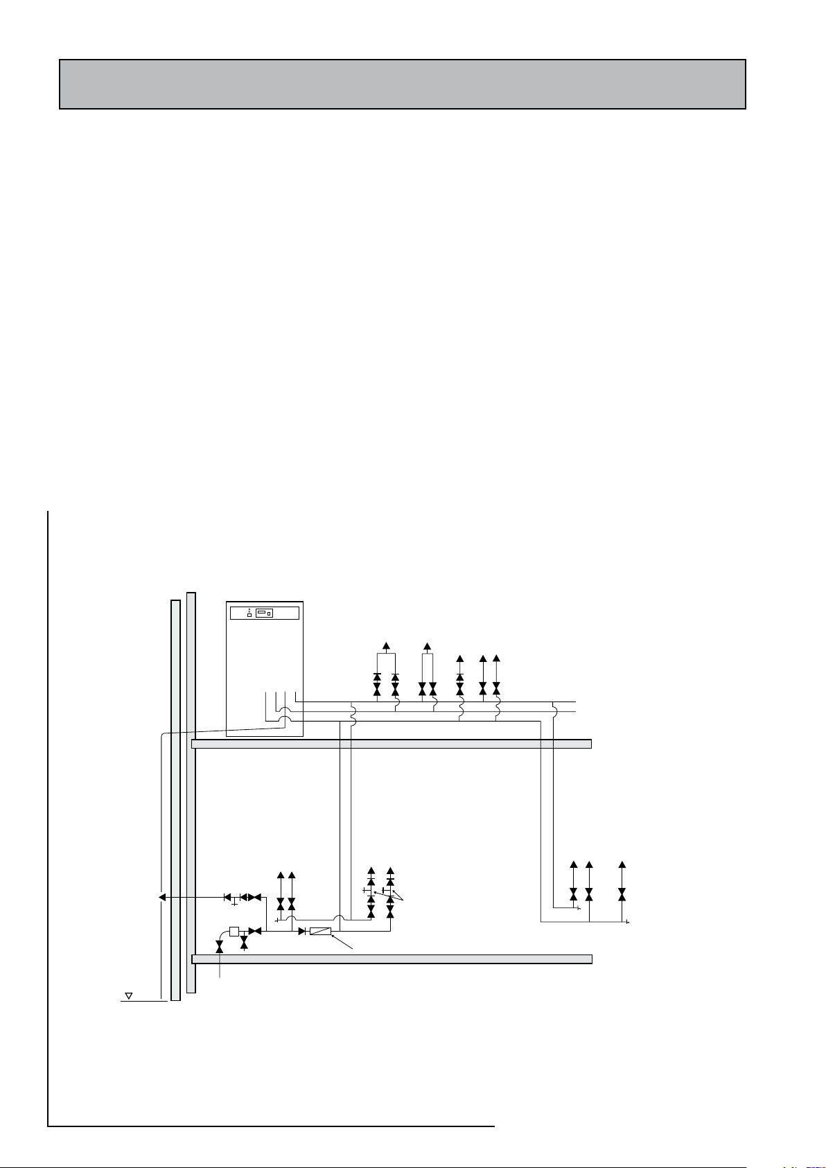
cold services are in 22mm past the draw-off to the bath as shown schematically
in figure 2.1. For large properties bigger sizes will be necessary and these should
be proved by calculation in accordance with BS6700.
b. The highest hot or cold water draw-off point should not exceed 4 metres above
the appliance.
c. In typical dwellings, the cold water supply to any mixer fittings (other than dual
outlet fittings) should be taken from the balanced cold outlet connection on the
appliance. However, in larger dwellings with a number of bathrooms and en-suites
and long pipe runs, the balanced cold supply must be provided with its own
pressure regulating valve (set at the same pressure as the one provided
with the appliance ie 1.5 bar static) and
not taken from the appliance. When a
separate pressure reg ulating valve is
used for the balanced cold water supply,
it is recommended that a small expansion
vessel (0.25 - 0.5 litre) is fitted after the
pressure regulator to accommodate the
pressure rise caused by the increase in
temperature of the balanced cold water.
d. Whenever possible the hot and cold water
supply to a shower-mixing valve should be
the first draw-off point on each circuit.
e. It is important that the cold water pipe work
is adequately separated from any heating/
hot water pipe work to ensure that the
water remains cold and of drinking water
quality.
Figure 2.1 Typical cold and hot water network
Cold supplies to single taps taken from the mains cold water system.
Cold supplies to mixer taps only to be taken from the balanced cold water connection on the combination valve.
Page 14
Page 15
1.0 DESIGN
SH
WHB
WHB
SCV
SINK
WC
BATH
1
2
3
4
1. Bronze circulator
2. Expansion Vessel
3. Hot water return pipework
4. Single check valve/non return valve - should be fitted
as close as possible to the Accolade 2000 appliance
1.3 SYSTEM DETAILS
Taps and Shower Fittings
a. Ensure that all terminal fittings are suitable
for mains pr essure. Use aer ate d taps
whenever possible to prevent splashing.
b. Aerated taps are recommended to prevent
splashing. Any type of shower mixing valve
can be used as long as both the hot and cold
supplies are mains fed. However, all mains
pressure systems are subject to dynamic
changes particularly when other hot and
cold taps/showers are opened and closed.
To minimise the impact of this we would
always recommend the use of thermostatic
showers with this appliance.
The shower head provided must also be
suitable for mains pressure supplies.
However, if it is proposed to use a ‘whole
body’ or similar shower with a number of
high flow/pressure outlets please discuss
with the Gledhill technical department.
c. Note that the shower fittings must comply
with the backflow prevention requirements
(Para 15, Schedule 2) of the Water Supply
Regulations 1999.
d. A bidet can be supplied from the Accolade
2000 appliance as long as it is of the over rim
flushing type and incorporates a suitable air
gap.
Dead leg volumes and secondary hot water
circulation
If the dead leg volume of the hot water draw-off
pipework is excessive and the delivery time for
hot water to be available at the tap is more than
60 seconds you may consider using:-
a. Trace heating such as the ‘Raychem HWAT’
system. Plea se ca ll Gledhill technical
department for further details.
OR
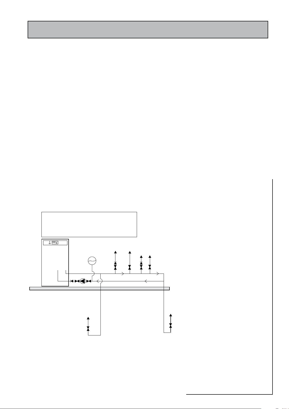
b. A secondary hot water circulation system
as shown schematically in figure 2.2.
Note:
It is not recommended that direct models
utilizing an E7 tariff are provided with a
secondary hot water circulation system.
Figure 2.2 Schematic diagram of secondary hot water circulation
2. All components must be suitable for use on domestic unvented hot water
1. Hot flow and return pipework must be insulated
storage systems
Page 15
2000
ACCOLADE
Page 16

1.0 DESIGN
1.3 SYSTEM DETAILS
Space Heating System Design (Indirect
models only)
General
Warning: Accolade
water storage applia nce and therefore
it is not suitable for use with a solid fuel
boiler, steam or any other uncontrolled
heat source.
Model selection
Indirect Accolade
for open vented heating systems (figure 3.3)
only.
The ‘-SS’ models are supplied with a sealed
system kit and are therefore suitable for sealed
heating systems only (figure 2.3).
I t is d esigned to b e installe d wi t h any
condensing or non condensing gas or oil fired
boilers which has a controlled heat source and
is suitable for sealed heating systems i.e. fitted
with an overheat thermostat.
Although general model selection guidance
is given in table 2.1 (section 1.2), it is
recommended that the hot water demand
should be determined before selecting the
correct model.
2000
is an unvented hot
2000
models ‘-OV’ are suitable
Plastic pipework
All recommendations with regard to pipework
systems in this manual are generally based on
the use of BS/EN Standard copper pipework
and fittings. However plastic pipework can
be used in place of copper internally as long
as it is recommended by the manufacturer
and installed fully in accordance with their
recommendations. Barrier type plastic pipework
should always be used for these systems.
It is important to ensure that if the system
is to be installed using plastic pipework it is
designed and sized for plastic pipework. This is
particularly important in relation to use of push
fit connections to the appliance.
Boiler Sizing
The indirect Accolade
in a ‘flow share’ mode i.e. the boiler may supply
sp ace heat ing and hot water demands
simultaneously. Therefore a hot water allowance
should be included when sizing the boiler and
heating system in accordance with BS 5449.
The heating system design and installation
must comply with the requirements of BS
6798 and BS 5449.
2000
is designed to operate
Page 16
Page 17
1.0 DESIGN
Boiler
Accolade
2000
A
B
C
Expansion Vessel
Manual
Air Vent
Manual
Air Vent
PRV,PG &
Filling Loop assembly
1.3 SYSTEM DETAILS
Frost protection
If it is necessary to protect parts of the heating system or the boiler which are installed in
unheated spaces (e.g. garage, outhouse and ventilated roof space), a frost thermostat(s)
must be fitted and wired as shown in section 5. The Accolade 2000 appliance should
not be installed in a location where the contents could freeze.
User controls
The indirect Accolade2000 models are supplied with a factory fitted 2-channel digital
heating and hot water programmer. A room thermostat will be required and this should
fitted and wired to the appliance as shown in section 5 to meet the ‘boiler interlock’
requirements of Building Regulations, Part L.
System bypass
An automatic bypass valve is built into the appliance to allow thermostatic radiator
valves (TRV’s) to be fitted. To meet the requirements of Building Regulations for a boiler
interlock it is recommended that the radiator in the area where the room thermostat
is installed should be fitted with lock shield valves on both connections.
The bypass valve is set at the factory to 2m head but this should be adjusted on site by
the installer to ensure that there is an adequate (the minimum flow rate recommended
by the boiler manufacturer) flow rate through the boiler when TRVs are closed.
Pump head
The net pump head available when hot water
only or space heating only are on is shown in
figures 1.6 and 1.7 respectively. The net pump
head available for sizing the boiler radiator
circu it should be cal culated us ing th ese
figures.
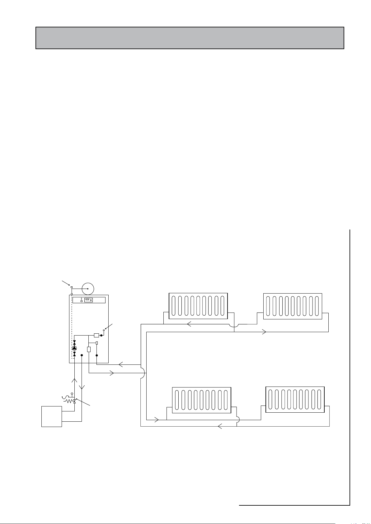
Sealed central heating system
Sealed system kit
Only ‘–SS’ Accolade models are suitable for
sealed central heating systems and these are
supplied with a sealed system kit consisting
of:
• Expansion relief valve set at 3.0 bar
• Pressure gauge (0 – 4 bar)
• Primary expansion vessel charged to 1.0 bar,
(Size depends upon the model, see table
2.1)
• WRAS approved primary system filling
loop
2000
Figure 2.3 Schematic diagram of a sealed heating system
ACCOLADE
Page 17
Page 18
stnemeriuqerlessevnoisnapxeyramirP1.3elbaT
)rab(gnittesevlavytefaS 0.3
)rab(erusserpegrahclessevlaitinI 0.1 5.1
)rab(erusserpmetsyslaitinI 0.1 5.1 5.1 0.2
)1(metsysfotnetnocretawlatoT )sertil(emulovlessevnoisnapxE
02 2.2 8.3 1.3 6.6
04 4.4 6.7 2.6 2.31
06 5.6 4.11 4.9 9.91
08 7.8 2.51 5.21 5.62
001 9.01 0.91 6.51 1.33
021 1.31 8.22 7.81 7.93
051 4.61 5.82 4.32 7.94
081 6.91 2.43 1.82 6.95
metsysehtylpitlumsemulovrehtoroF
rotcafybtnetnoc
901.0 091.0 651.0 133.0
1.0 DESIGN
1.3 SYSTEM DETAILS
Pressure gauge and filling loop
Primary
The pressure gauge and the filling loop should
be fitted at the system filling point which it is
recommended should be adjacent to the
boiler.
There shall be no permanent connection to
the mains water supply for filling the system,
even through a non-return valve without
the approval of the Local Water Authority.
The approved filling loop supplied with the
applia nce should be disconnec ted after
commissioning the system.
Pressure relief valve
Primary
The pressure relief valve must be fitted in the
boiler flow pipe adjacent to the boiler. There
must no isolating valves or any such devices
between the boiler and the pressure relief
valve. The pressure relief valve should be fitted
in a position where it is accessible for testing/
inspection.
The method of fitting should ensure that
discharge of water or steam cannot create a
hazard to persons in or about the premises or
damage to electrical components or wiring and
the point of discharge shall be clearly visible.
Expansion vessel
Primary
The expansion vessel is designed be sited on
top of the appliance and connected to the
15mm copper pipe provided at the top of the
appliance (see figure 2.3).
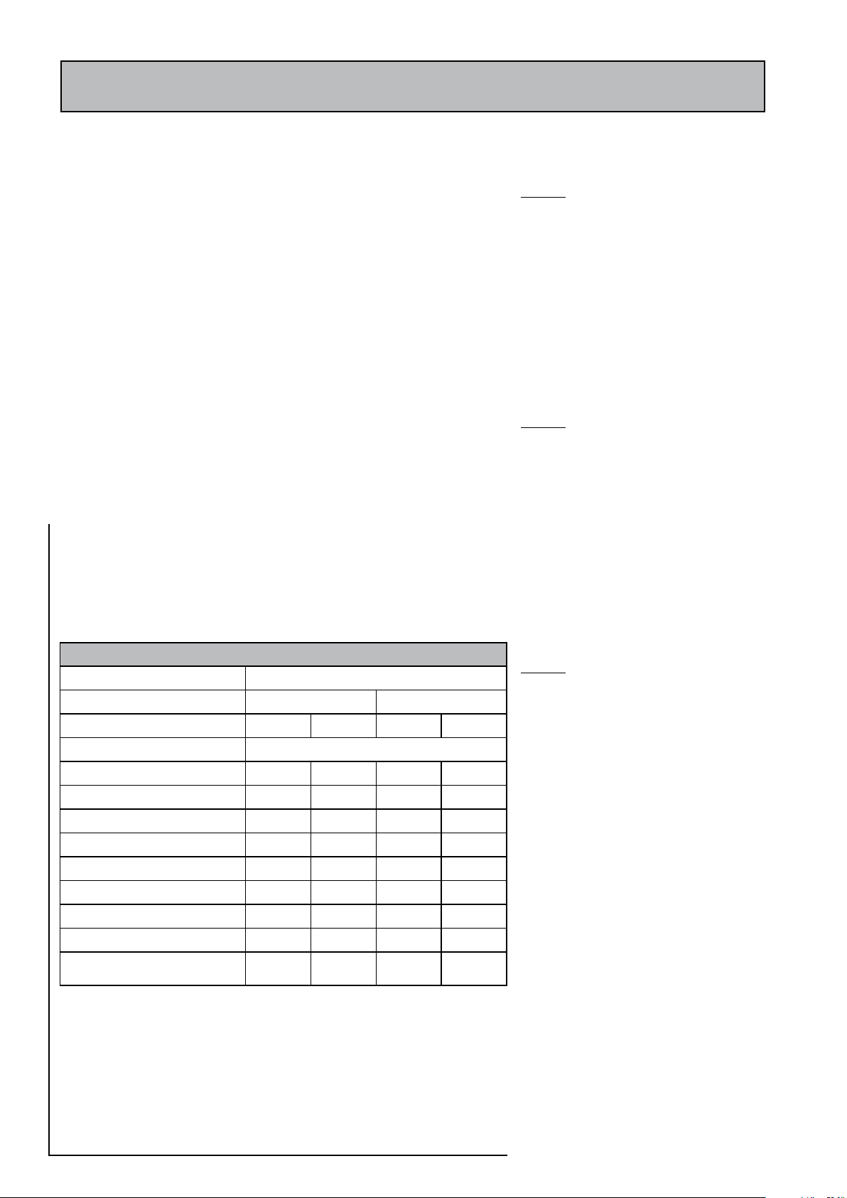
The expansion vessel must accommodate the
change in volume of system water when heated
from 10oC to 110oC (see BS 5449:1990 clause
16.2). When calculating the system water
content, the water content of the primary heat
exchanger (see table 2.1) must be included.
The expansion vessel requirements are shown
in table 3.1.
Note 1
After first filling the system to a pressure of 1.0
bar at mains supply temperature (typically 15oC
in summer), the total system (space heating and
hot water) should be heated to its maximum
temperature. If the primary pressure gauge
indicates 2.6 bar or higher, then an additional
expansion vessel may be required.
Note 2
If the system pressure required is more than 1.0
bar, then the expansion vessel charge pressure
should be adjusted to match the primar y
system pressure and the expansion vessel size
recalculated accordingly.
Page 18
Page 19
Open vented heating system
Boiler
Accolade
2000
CW Supply
F&E Cistern
Overflow
SV
A
B
C
Manual
Air Vent
1.0 DESIGN
1.3 SYSTEM DETAILS
Cold feed/expansion and safety/open vent
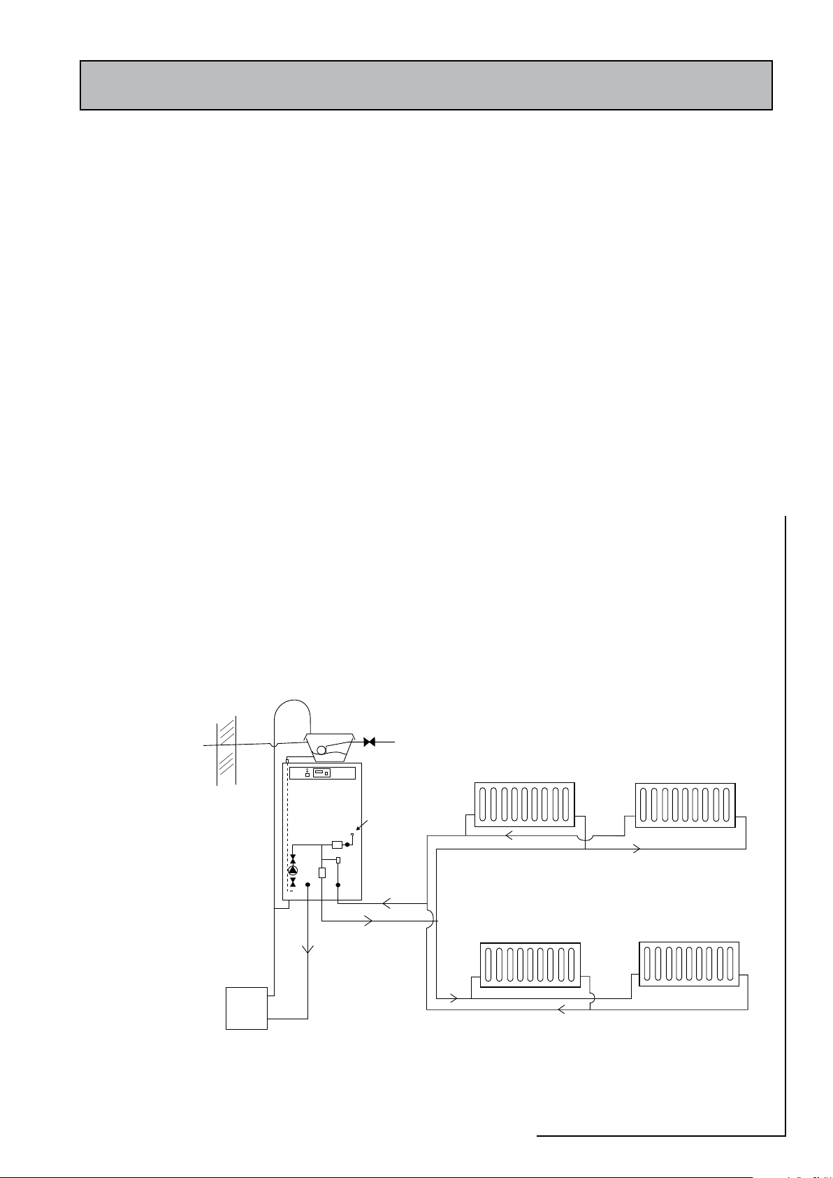
Open vented system kit
The ‘-OV’ models are only suitable for an open vented heating system and these are
supplied with the following components for onsite installation.
• Feed and expansion cistern with lid
• Ball valve & float
• 22mm Overflow pipe connector
• 15mm Cold feed tank connector
F & E cistern
The feed and expansion cistern supplied with the unit, can be fitted up to 10m above
the base of the appliance i.e. the maximum static pressure in the appliance must not
exceed 1.0 bar (figure 2.4). The water level in the F & E cistern should be at least 250mm
above the highest point on the system including the radiators.
Overflow pipe
The overflow/warning pipe should be installed using 20mm internal diameter pipe
of a suitable material to comply with BS 5449 (such as copper). It should have a
continuous fall and be discharged in a conspicuous external position. It should not
have any other pipework directly branched into it.
The cold feed connection is provided at the top
of the appliance. The safety/open vent should
be connected into the boiler flow pipe ensuring
that there is a continuous rise from the boiler
to the point of discharge over the F & E cistern
as shown schematically in figure 2.4. The open
vent and cold feed should be run in 22mm and
15mm copper (respectively) or equivalent to
the feed and expansion cistern. There must no
isolating valves or any such devices between
the boiler and the safety/open vent connection
point.
Discharge Arrangements
It is the requirement of Building Regulation
Approved Document G3 that any discharge
from an unvented hot water storage system
is conveyed to where it is visible but will
not cause danger to persons in or about the
building. Therefore the discharge pipe from
the appliance tundish should be fitted in
accordance with the requirements and typical
arrangement as shown in figure 2.5.
The discharge pipe MUST terminate in a SAFE
and VISIBLE position. For a 22mm discharge it
must have an equivalent length of no more
than 9 metres and it must have a continuous
fall (1:200 minimum) throughout its length.
Figure 2.4 Schematic diagram of open vented heating system
2000
ACCOLADE
Page 19
Page 20
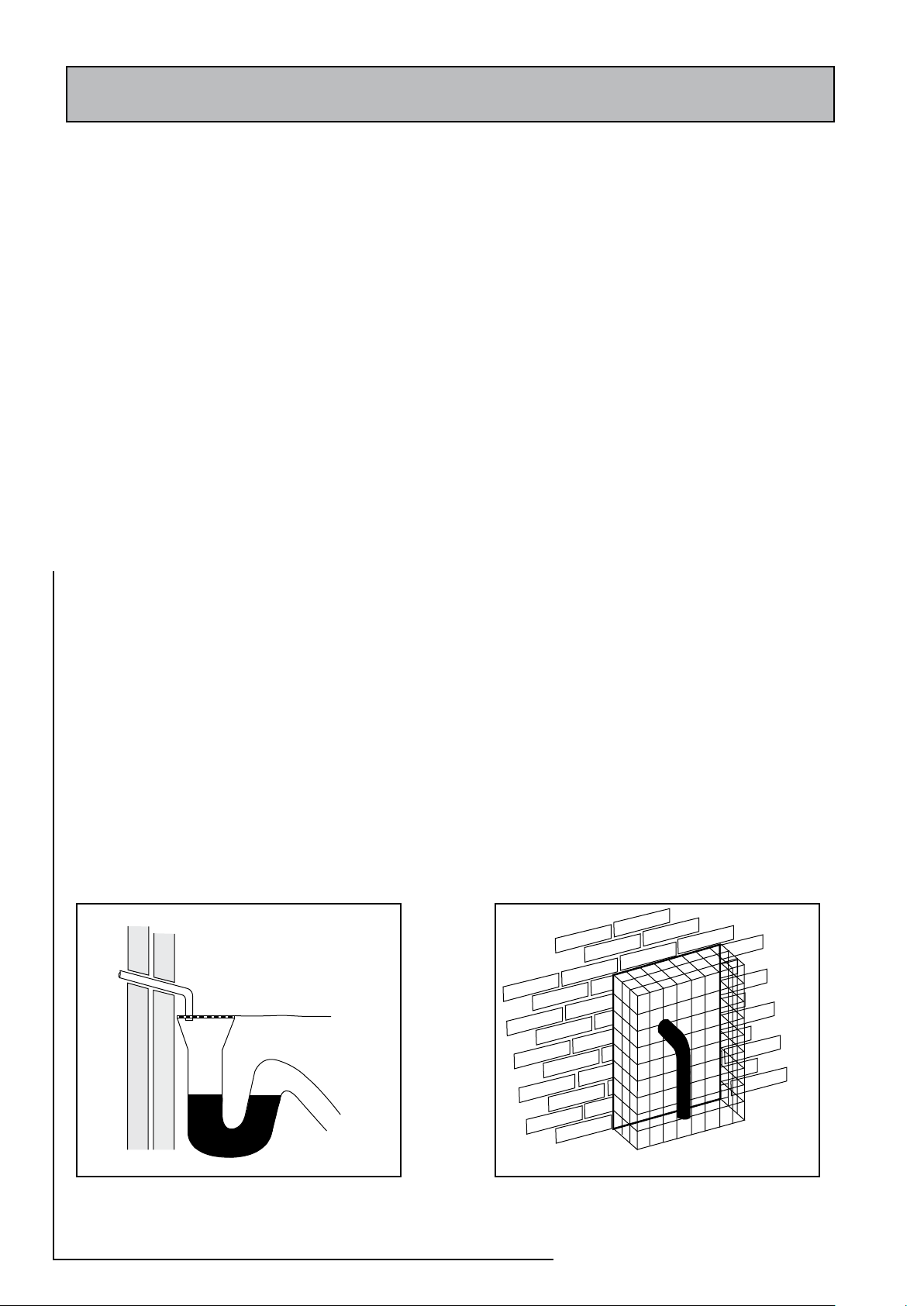
Diagram 1
Diagram 2
Discharge into a gully
Discharge onto the ground
1.0 DESIGN
1.3 SYSTEM DETAILS
In apartment/flat situations the discharge pipes
can be connected into a single pipe which is
discharged at low level. In this case the number
should be limited to 6 to allow the fault to be
easily traced. The single pipe should be at
least one size larger than the largest individual
discharge pipe to be connected.
The discharge can consist of scalding water
and steam therefore the pipework should be
metal.
The following locations for the discharge pipe
are acceptable:
Low Level
• Into a gully below the grating but above the
water level (see diagram 1).
• Onto the ground (drive, parth or garden
area). The pipe should discharge downwards
and be no more than 100mm above ground
level. A wire cage should be provided to
prevent people coming into contact with
scalding water (see diagram 2).
High Level
High level discharge is only acceptable if it is :
• onto a flat or pitched roof capable of
withstanding high temperature water and
at least 3m away from plastic guttering.
or
• into a metal hopper and down pipe which
terminates at low le vel (as descri bed
above.)
Discharge into a soil or waste pipe (whether
plastic or metal) is not acceptable.
Figure 2.5
Page 20
Page 21

The appliance is designed to be installed in an airing/cylinder cupboard and the
relevant minimum dimensions are provided in section 1.2 Technical Data.
Because of the ease of installation we recommend that the cupboard construction is
completed and painted before installation of the appliance. The cupboard door can
be fitted after installation.
If the unit needs to be stored prior to installation it should be stored upright in a dry
environment and on a level base/floor.
Installation and maintenance access is need ed to the front of the appliance and
above the F & E cistern. See section 1.2 Technical Data for further details.
The minimum dimensions contained in section 1.2 Technical Data allow for the
passage/connection of pipes to the appliance from any direction as long as the
appliance is installed on the installation base provided. If the installation base is not
used extra space may be needed to allow connection to the pipework and the whole
of the base area should be continuously supported on a material which will not easily
deteriorate if exposed to moisture.
The floor of the cupboard needs to be level and even and capable of supporting
the weight of the appliance when full. Details of the weight when full is provided in
section 1.2 Technical Data.
2.0 INSTALLATION
2.1 SITE REQUIREMENTS
The appliance is designed to operate as quietly as practicable. However, some noise
(from pumps etc) is inevitable in any heating system. This will be most noticeable
in cupboards formed on bulkheads, or at the mid span of a suspended floor. In these
cases the situation can be improved by placing the appliance on a suitable sound
deadening material (i.e. carpet underlay or similar).
The cylinder is very well insulated and no ventilation is normally required to the
cupboard.
A suitable location will be needed for the separate feed and expansion cistern (OV
model) or expansion vessel (SS model). This will often be on top of the appliance
itself or at high level in the cupboard housing the Accolade 2000. The dimensions
and clearances are provided in section 1.2 Technical Data. The location will need
to provide a suitable route for the cold feed/expansion pipe and safety/open vent
pipe for the appliance (OV model) or the connecting pipe to the system expansion
vessel (SS model). A suitable route and discharge position for the warning/overflow
pipe and the ballvalve supply from the mains cold water system will also be required with
the OV model.
An electrical supply must be available which is correctly earthed, polarized and in
accordance with the latest edition of the IEE requirements for electrical Installations BS
7671.
The electrical mains supply needs to be 230V/50Hz/1Ph
Connection must be made using a double-pole linked isolator with a contact
separation of 3mm in both poles which is located within 1m of the appliance. The
supply must only serve the appliance.
The supply to all the indirect appliances shall be fused at 16 amp.
The on and off peak supplied to all the direct models shall each be fused at 16 amp.
Normally these will be provided from a suitable off peak hot water controller located
adjacent to the appliance.
Page 21
2000
ACCOLADE
Page 22
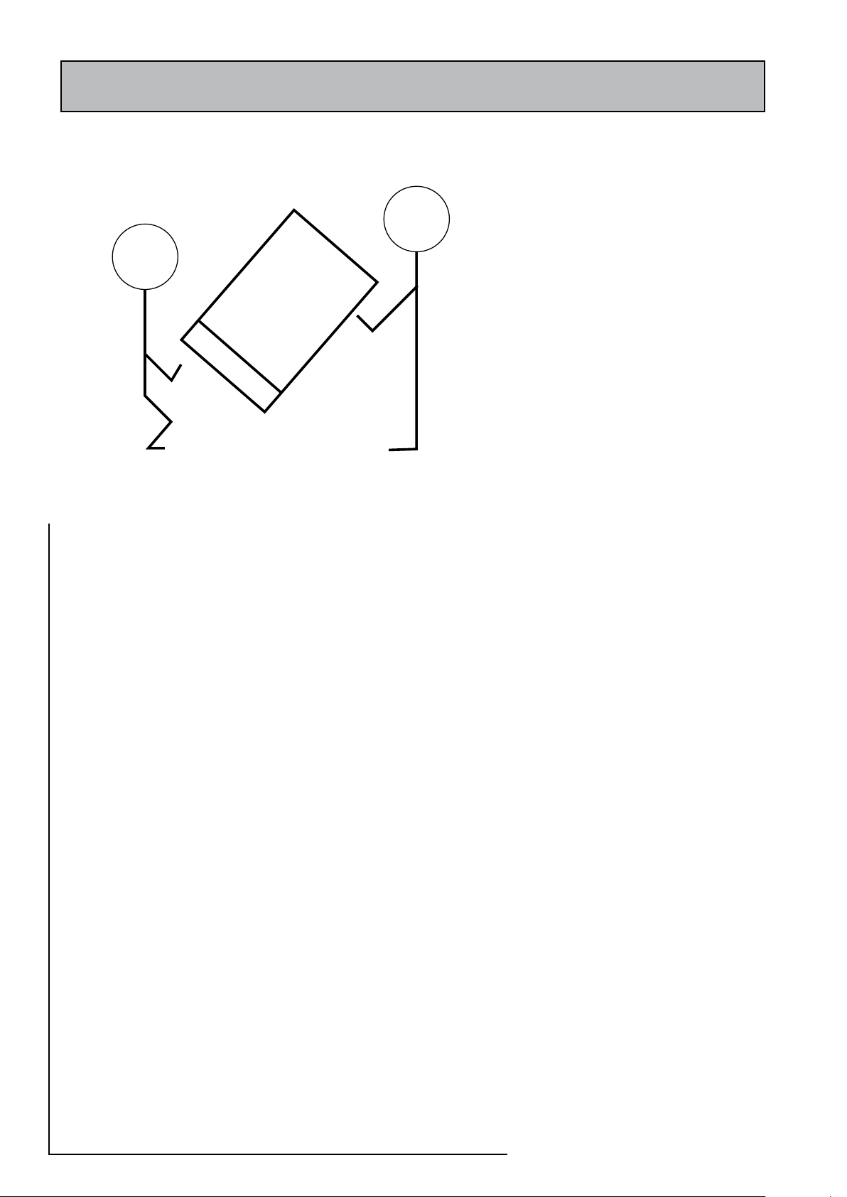
When lifting the unit work with someone of similar build and height if possible
Choose one person to call the signals
Lift from the hips at the same time, then raise the unit to the desired level
Move smoothly in unison
Larger units may need team lift
2.0 INSTALLATION
2.2 INSTALLATION
Prepar atio n/p lacin g the ap plian ce in
position
Details of the recommended positions for
termination of the first fix pipework are
provided in section 1.2 Technical Data. The
pipework can be located or its position
checked using the template provided with
each appliance. If thse have been followed
installation is very simple and much quicker
th a n any o ther sy stem. The applia nce
is supplie d shrink wr app ed on a timbe r
installation base. Carrying handles are also
provided in the back of the casing.
A feed and expansion cistern complete with
ballvalve, cold feed/expansion and overflow/
warning fittings are provided in a separate
box with the OV models. If the SS model
is provided the box will contain a primary
system expansion vessel. It is the installers
responsibility to check that the size of cistern/
expansion vessel provided is adequate for the
primary/heating system being installed. If
flexible connection have been ordered these
will also be inside the feed and expansion
cistern/expansion vessel box.
The appliance should be handled carefully to
avoid damage and the recommended method
is shown opposite. Further details are provided
on pag e 2 of these ins tru ctions. Before
installation the site requirements should be
checked and confirmed as acceptable. The
pl ast i c cover a nd p r o tective wr a p p ing
should be removed from the appliance and
the installation base (provided) placed in
position.
The appliance can be then be lifted into
position in the cupboard on top of the base
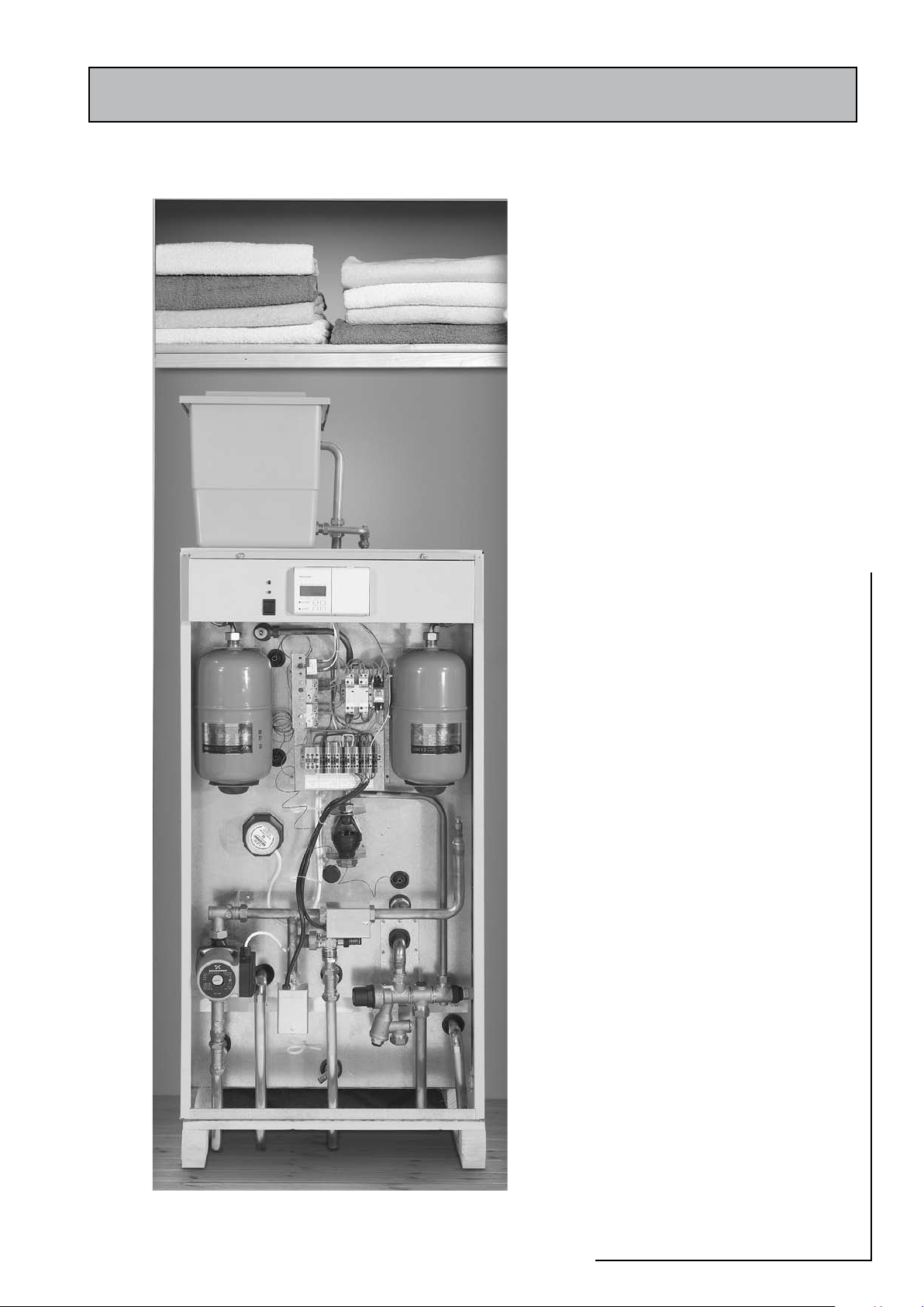
and the front panel removed by unscrewing
the 2 screws and lifting the door up and out
(see opposite) ready for connection of the
pipework and electrical supplies. If they are not
being fitted on top of the appliance a support
shall be installed for the feed and expansion
cistern/expansion vessel ensuring that the base
is fully supported and the working head of the
boiler/system is achieved. The recommended
access for maintenance must also be provided
- see section 1.2 Technical Data.
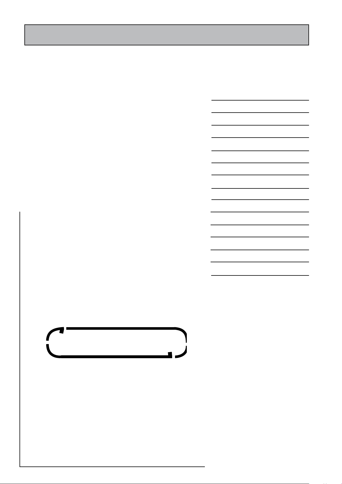
Photo of Accolade with front cover open
Page 22
Page 23
2.0 INSTALLATION
2.2 INSTALLATION
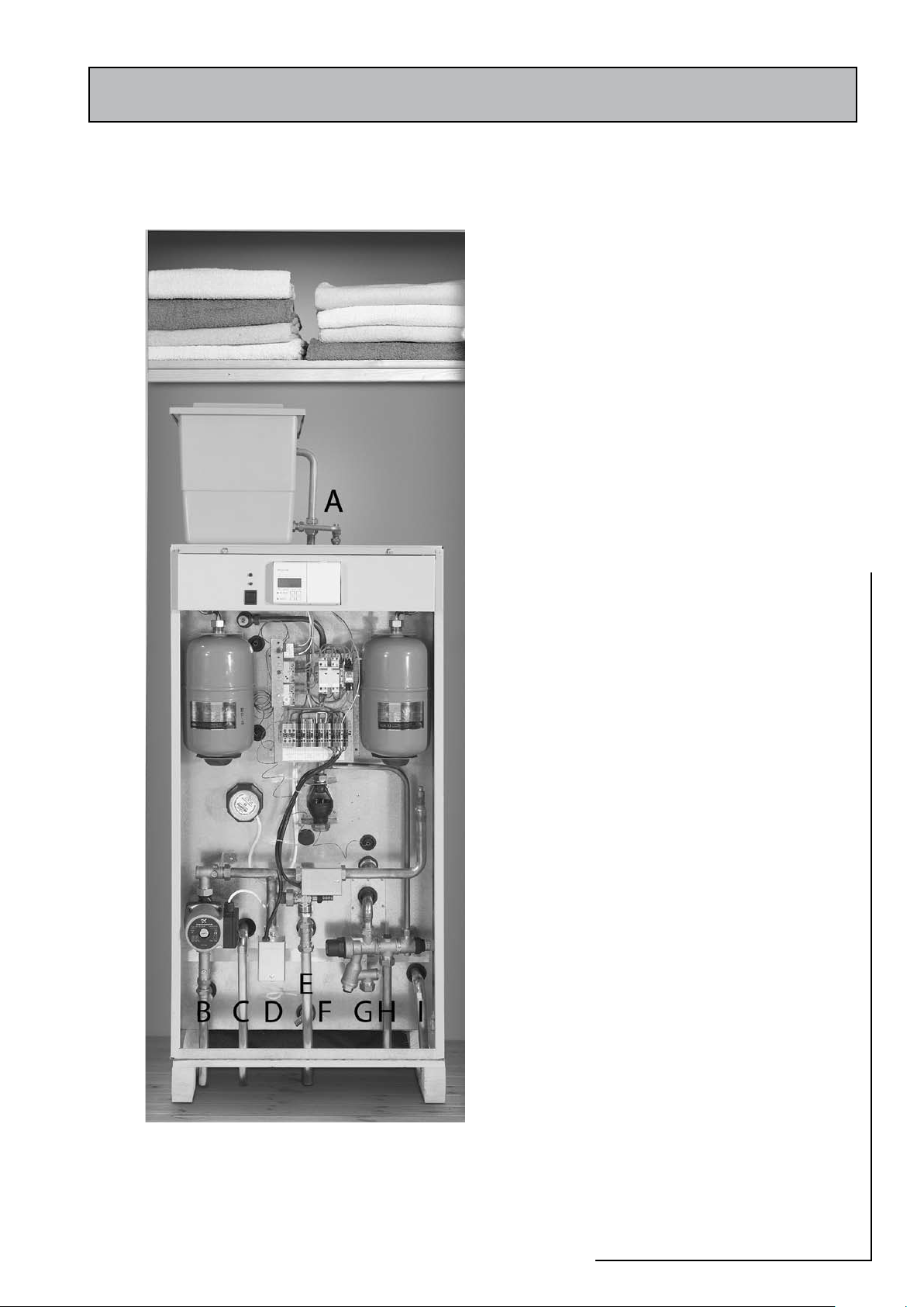
Pipework connections
The position of the pipework connections is
shown opposite . The connection sizes and
dimensions are listed in Section 1.2 Technical
Data.
All the connections are also labelled on the
appliance. It is essential that the pipework is
connected to the correct connection.
The connections can be hard piped but we
recommend the use of flexible connections
(available as an optional extra).
When using the psuh fit connectors with the
flexible hose kits it is important to check that
they are compatible. Written approval has
already been obtained for :Hepworth - Hep2O BiTite
John Guest - Speedfit
Yorkshire - Tectite
However, as similar assurances cannot be
obtained for Polypi pe fitt ings we cannot
recommend their use at this time.
Connections :-
A. Safety open vent / Cold feed/expansion
(OV model) / Expansion vessel pipe (SS
model)
B. Primary flow (from boiler)
C. Primary return (to boiler)
D. Central heating flow
E. Central heating return
F. D rain (valve is not provided with the
appliance)
G. Incoming mains water
H. Balanced pressure cold outlet
I. Domestic hot water
Note: With the OV model the safety open vent
and cold feed/expansion should be combined
before connecting to the appliance.
Page 23
2000
ACCOLADE
Page 24
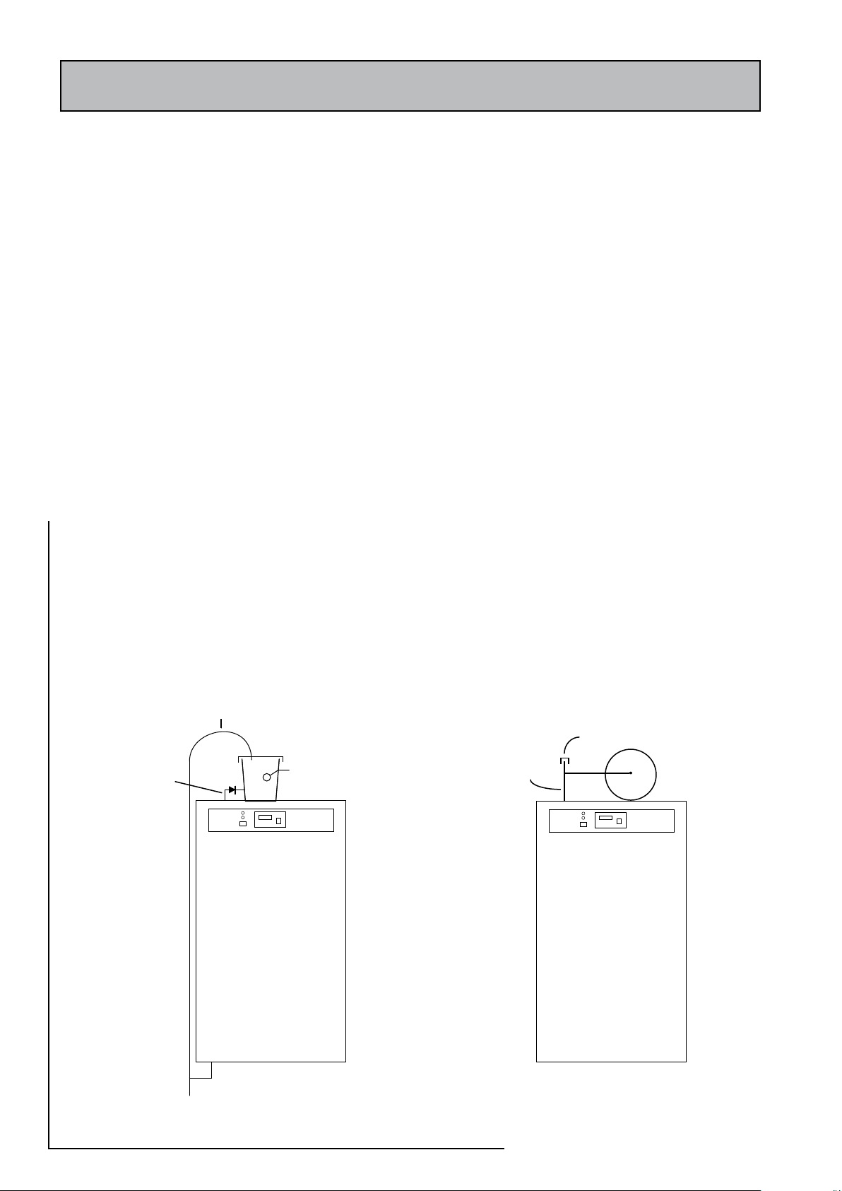
All factory made joints should be checked after installation in case they have
Accolade 2000
OV Model
SS Model
Accolade 2000
F & E
Cistern
22mm Safety
Open Vent
15mm valved
cold feed/expansion
Manual air vent
15mm expansion
pipe
Expansion vessel
been loosened during transit.
OV Model
The fittings for the feed and expansion cistern should be installed and the cistern fitted
on top of the appliance/on its supports.
The 22mm safety/open vent shall rise continuously from the boiler and terminate in
the F & E Cistern.
The 15mm cold feed/expansion shall be connected from the F & E Cistern to the
connection provided on the top of the appliance.
No valves should be fitted in the safety open vent which must be a minimum of 22mm
copper pipe or equivalent.
The overflow/warning pipe shall have a continuous fall, be fitted to discharge clear of
the building and be sited so that any overflow can be easily observed. It shall also be
installed in a size and material suitable for use with heating feed and expansion cisterns
in accordance with BS 5449 and should not have any other connections to it.
SS Model
The expansion vesel should be fitted on top of the appliance/supports provided and
connected to the appliance using a manual air vent at the high point.
2.0 INSTALLATION
2.2 INSTALLATION
It is normally envisaged that the feed and expansion cistern/expansion vessel will be
located in the same cupboard as the Accolade 2000 appliance. In the case of the OV
model this will allow a dry roof space.
However, if it is necessary to locate the cistern in the roof space any pipework in the
roof space and the feed and expansion cistern will need to be adequately insulated
to protect against frost damage.
Page 24
Page 25
2.0 INSTALLATION
230V, 50Hz, 16A
L N E
Double pole
fused isolator
Contactor
IH control
thermostat
IH overheat
thermostat
Immersion
heater
Inside immersion heater head
Pump
3A Fuse
Safety Limit
thermostat
Red LED_1
Contactor
coil
2-P ole CO
switch
L
N
N
N
L L
Room
therm ostat
Energy
cut-out
thermostat
Control
thermostat
programmer
HW zone valve
HTG zone valve
N
L
SL
N
Boiler
Red LED_2
HW
HTG
Green LED_1
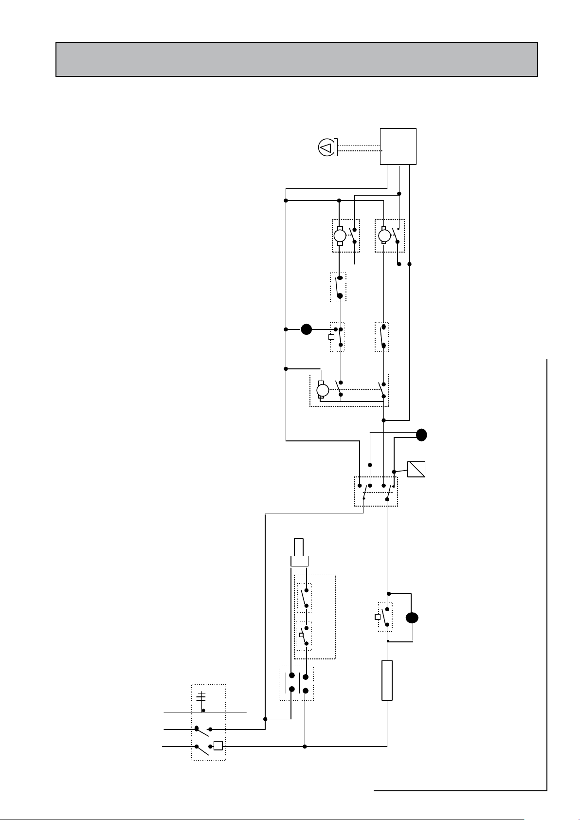
Typical diagrammatic arrangement of the electrical wiring for the indirect model
2.2 INSTALLATION
2000
ACCOLADE
Page 25
Page 26
2.0 INSTALLATION
5A fuse
A1
A2
1
2
3
4
2-pole
CO switch
L
N
E
Immersion
heater
L
N
E
Pu mp
N
To
Boiler
E L N E
L
S
L
N E
To
Room
thermostat
L
2
From
Boiler
(PUMP)
L N E
S
L
Mains Supply
230V ~, 16A , 50Hz
L
L N E
L
SL
Ranco OHT_2
L
N
L
1
E
L
2
L N
L
1
E
L
2
HTGZone valve
brown
grey
blue
orange
g/y
HW Zone v alve
brown
grey
blue
orange
g/y
Red LED_1
L
N E 4 3
Heating Progr ammer
C
1
Store CT
C
1
OHT_1
Red LED_2
HW
ON
HT
ON
2
Green LED
5A fuse
A1
A2
1
2
3
4
2-pole
CO switch
L
N
ELN
E
Immersion
heater
L
N
E
Pu mp
L
N
E
Pu mp
NN
To
Boiler
E LL NN EE
LL
S
L
NN EE
To
Room
thermostat
L
2
From
Boiler
(PUMP)
L N E
S
L
Mains Supply
230V ~, 16A , 50Hz
L
L N E
L
SL
Ranco OHT_2
L
N
L
1
E
LL
NN
L
1
EE
L
2
LL NN
L
1
EE
L
2
HTGZone valve
brown
grey
blue
orange
g/y
HTGZone valve
brown
grey
blue
orange
g/y
HW Zone v alve
brown
grey
blue
orange
g/y
HW Zone v alve
brown
grey
blue
orange
g/y
Red LED_1
L
N E 4 3
Heating Progr ammer
C
1
Store CT
C
1
OHT_1
Red LED_2
HW
ON
HT
ON
2
Green LED
Wiring Diagram - Indirect model
2.2 INSTALLATION
Page 26
Page 27
2.0 INSTALLATION
Schematic wiring diagram of Direct A ccolade
2000
(
Ver
: 260603)
A1
A2
123
4
E
L N E
N
ON-PEAK
Supply
230V~, 16A, 50Hz
L
L N E
L
SL
Ranco OHT_1
Red
LED
L N E
OFF-PEAK
Supply
230V~, 16A, 50Hz
TOP
On-Peak IH
L N E
TOP
-Peak IH
L N E
A1
A2
1
2
3
4
BOTOM
Off-Peak IH
L N E
BOTOM
Off-Peak IH
L N E
3A f use
3A f use
L
SL
Ranco OHT_1
Red
LED
Wiring Diagram - Direct Model
2.2 INSTALLATION
2000
ACCOLADE
Page 27
Page 28
2.0 INSTALLATION
N
E L N E
L
S
L
N E
L N E
S
L
L
L N E
L N E
L L N E L L N E
N
N
E
LLNNE
E
L
L
S
L
NNE
E
L N E
S
L
L
To
Room
Thermostat
From
Boiler
(PUMP)
To
Boiler
Mains Supply
230V~, 16A, 50Hz
1
2
3
4
5
6
7
8
9
10
11 12
13
14
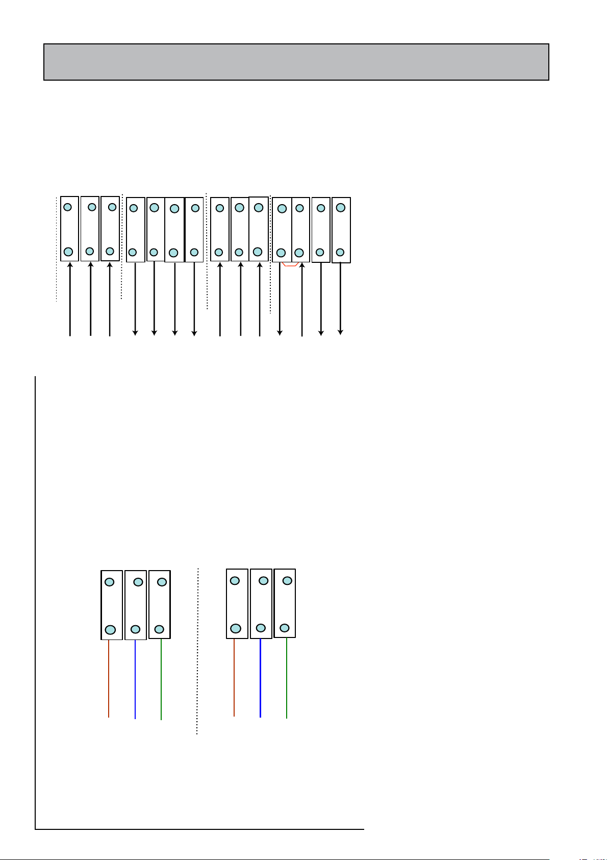
Note: Link between 11 and 12 to be removed if a
room thermostat is fitted
L N E
L N E
L N E
ON-PEAK
Supply
230V~, 16A, 50Hz
OFF-PEAK
Supply
230V~, 16A, 50Hz
1
2
3
L N E
L N E
L N E
4
5
6
2.2 INSTALLATION
Electrical Connection - Indirect Appliance
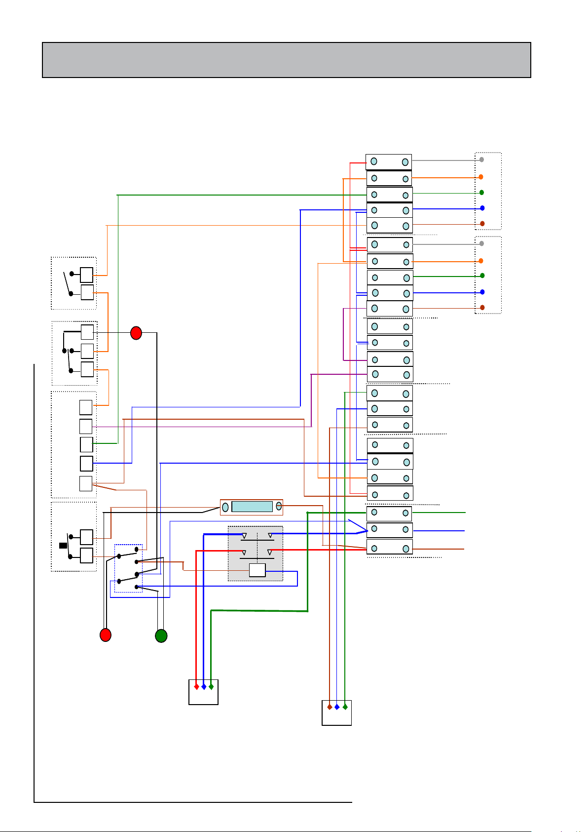
The Accolade 2000 is pre-wired to a 24 way
terminal strip and plumbers are well able to
complete the electrical installation provided
they adhere strictly to the IEE Requirements
for Electrical Installations BS 7671. A schematic
arrangement of the wiring is shown opposite.
Terminals 1 - 14 shoul d be wired on site
in accordance with the diagram opposite.
Terminals 15 - 24 are pre-wired to components
fitted on the appliance.
All the terminals are suitably labelled on the
appliance.
Note: Do not attempt the electrical work unless
you are competent to carry it out to the above
standards.
Before commencing check that the power
source is in accordance with section 1.2 Site
Requirements and ensure that it is isolated.
The boiler manufacturers wiring instructions
should be read in conjunc tion wi th this
manual.
Run the external wiring through the service slot
provided in the base of the appliance.
Make the connections as shown opposite on
the terminal strip provided.
The appliance is provided with a link between
terminals 11 and 12 on the terminal strip.
This must be removed if a room thermostat
is fitted.
Electrical Connection - Direct Appliance
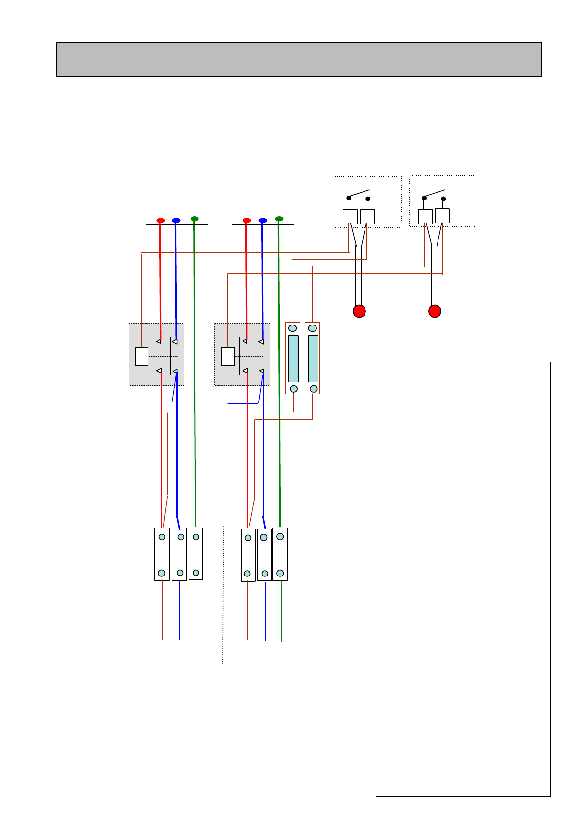
The Accolade 2000 is pre-wired to 2 x 3 way
terminal strip and plumbers are well able to
complete the electrical installation provided
they adhere strictly to the IEE Requirements
for Electrical Installations BS 7671. A schematic
arrangement of the wiring is shown opposite.
Both sets of terminals shall be wired on site from
a suitable off peak hot water controller.
All the terminals are suitably labelled.
Note: Do not attempt the electrical work unless
you are competent to carry it out to the above
standards.
Page 28
Page 29

2.0 INSTALLATION
2.2 INSTALLATION
Before commencing the electrical work check
that the power source is in accordance with
section 1.2 Site Requirements and ensure that
it is isolated.
When installing the indirect unit the boiler
manufacturers wiring instructions should be
read in conjunction with this manual.
Run the external wiring through the service slot
provided in the base of the appliance.
Make the connections as shown opposite on
the terminal strip provided.
Before switching on the electrical supply
check a l l the f ac t o r y m a de ter m i n a l
connections to ensure they have not become
loose during transit and that the appliance
is full of water.
Frost Protection
When frost protection is required for the
whole house set the programmer to constant
during the time required and adjust the room
thermostat to a suitable setting.
Page 29
2000
ACCOLADE
Page 30

2.0 INSTALLATION
SYSTEM FILLING/CLEANSING
Check and adjust as necessary the hot water system expansion vessel(s) air pressure
to 1.5 bar.
Check that any drain valves are closed then open the incoming stop valve and fill the
domestic mains cold and hot water systems in the normal way ensuring there is no
air trapped in the system.
In the case of the OV model fill the heating system with potable water through the
feed and expansion cistern flush and refill.
Check the water level in the feed and expansion cistern and adjust the ballvalve if
necessary.
Check the warning pipe is installed correctly, has a continuous fall and is not blocked
i.e. discharges water freely.
Check and adjust as necessary the primary heating system expansion vessel to the
figure specified (normally 1.0 bar)
Note: The expansion vessel pressures should be checked before the systems are
filled.
In the case of the SS model fill the primary heating system with potable water through
the filling loop provided adjacent to the boiler to the pressure required (normally
1.0 bar).
During filling vent air as necessary from the high points of the system including
the manual air vents provided on the appliance and on the feed to the expansion
vessel.
Check the whole of the primary heating and domestic hot and cold distribution
systems for leaks.
It is essential that all systems functions properly for optimum performance.
To achieve this, the primary system should be commissioned in accordance with good
practice and generally in accordance with the requirements of BS 6798, BS 5449 and
BS 7593.
Full details of the requirements are given in PAS 33:1999 under Section 10
Commissioning.
2.3 COMMISSIONING
POWER F LUS HI N G/CLE A NING O F TH E
HEATING SYSTEM
If it is proposed to ‘powerflush’ the heating
system always check and comply fully with
th e ma nuf acture rs i nst ruc tions f o r t he
powerflushing equipment being used.
If in any doubt please consult our Technical
Helpline.
Cleans ing the Hot/Cold Water System
Treatment
Fully flush and, when necessary, chlorinate the
hot and cold water system in accordance with
the recommendations in the Model Water
Byelaws and BS 6700.
Remove and clean the strainer element in the
combination inlet valve, then replace it and
re-fill the system.
Manually open the relief valves one by one and
check that water is discharged and runs freely
through the tundish and out at the discharge
point. The pipework should accept full bore
discharge without overflowing at the tundish,
and the valve should seat satisfactorily.
With the OV model once the system is
finally filled turn down the servicing valve
for the ballvalve in the F & E Cistern to the
point where the warning/overflow will cope
with the discharge arising from a ballvalve
failure.
With the SS model disconnect the manual
filling loop.
When using either cleansing or corrosion inhibitor chemical, the manufacturers
instructions must be followed.
Cleansing the Primary System
It is very important to ensure that the Primary system is cleaned using a suitable
cleansing agent such as Sentinel X300 or Fernox Superfloc to ensure that any
flux residues/installation debris are removed.
The volumes/concentration should be calculated in accordance with the manufacturers
instructions allowing the volume for the primary coil shown in the Table in 1.2 Technical
Data.
Primary Water System Treatment
Although the Accolade 2000 has no special water treatment requirements, the radiators
and other parts of the circuit will benefit from the application of a scale and corrosion
inhibitor such as Sentinel X100 or a Protector such as Fernox MB1.
The volumes/concentration should be calculated in accordance with the manufacturers
instructions allowing the volume for the primary coil shown in the Table in 1.2 Technical
Data.
Page 30
Page 31

2.0 INSTALLATION
2.3 COMMISSIONING
Appliance Commissioning
Indirect Models
Check temperature settings are set at 60ºC. Turn on and check that thermostats and
all controls operate correctly as well as any motorised valves. Check that no water
discharges from either the expansion valve or temperature and pressure-relief valve
during the heating cycle. Check the temperature setting on the immersion heater is
set at 60ºC. Turn on and check it operates and switches off at the correct temperature.
Check the appliance, the heating system and hot water system for leaks when hot.
Direct Models
Check temperature settings on the immersion are set at 60ºC. Turn on and check
thermostat operates and switches off at the correct temperature. Ensure no water
discharges from either the expansion valve or temperature and pressure relief valve
during the heating cycle.
System Commissioning
Check that the correct outlet pressure is being
maintained on the domestic water systems by
the pressure reducing valve by checking the
pressure at a hot tap or in the tapping provided
on the combination inlet valve.
Check the correct flow is being achieved at each
tap and the implications of opening more than
one tap at the same time. If necessary fit flow
regulators to each tap.
The heating system is set to operate as a
standard ‘S’ plan and the pump and primary
sy ste m should be set and b a l a nced in
the normal way to provide a temperature
differential of 11ºC.
An automatic bypass valve is provided on the
primary/heating circuit. This is factory set to 2m
head but may need to be adjusted to suit the
particular installation requirements.
The clock/ programme r pr ovid ed on th e
appliance controls the heating and hot water
systems separately and should be set to suit
the householders requirements using the
instructions shown on the separate leaflet and
the label on the right hand drop down part of
the programmer.
Page 31
This product is covered by the ‘Benchmark’
scheme and a separate commissioning/
service log book is inclu ded with th is
product. This must be completed during
commissioning and left with the product
to meet the Warranty conditions offered
by Gledhill.
On completion:-
1. Do ensure that the electrical connections
(e.g. mains supply, room thermostat) to the
unit are correct and tight.
2. Do ensure that the functioning and control
of the system is explained to the occupant
and explain the need and importance of
periodic servicing.
3. DON’T place any clothing or other
combustible materials against or on top of
this appliance
These Instructions should be placed along with
the component manufacturers instructions in the
pocket provided on the rear of the front panel.
The front panel should then be refitted.
NOTE:- With sealed heating systems air is
released from the water during the first few
weeks of operation. This must be vented and
the system repressurized.
2000
ACCOLADE
Page 32

If the system is not likely to be used continuously after testing/commissioning it
should be isolated from the water and electricity supply and either drained down or
have the pressure removed from both the heating and water systems.
Important Do’s and Don’ts
DO check the incoming mains water pressure and flow rate are adequate. (The
preferred range of mains pressure is 2-3bar).
DO check and ensure that the air pressure side of the hot water exapnsion vessel(s)
is set at 1.5 bar.
DO check that all plumbing and electrical connections are in accordance with the
labelling on the unvented storage appliance.
DO insulate any exposed pipework in the Accolade 2000 cupboard.
DO plumb the overflow/warning pipe (if fitted) in a 20mm internal diameter pipe
material which is suitable for use with a heating F & E cistern, in accordance with
BS 5449 (such as copper) and ensure it has a continuous fall and discharges in a
conspicuous external position.
2.0 INSTALLATION
2.3 COMMISSIONING
DO check the pump setting to give a temperature difference across the flow and
return of not more than 11°C.
DO ensure that the bypass valve is set correctly.
DON’T use pipe smaller than 28mm between the boiler and the Accolade when
the boiler rating exceeds 20kW (about 68,000 Btu/h).
DON’T operate any immersion heaters until the appliance/systems are fully fitted,
vented and commissioned.
SS Models
DO check and ensure the air pressure side of the heating expansion vessel is set at
1.0 bar (or as specified)
DO ensure the boiler is suitable (i.e. fitted with an overheat thermostat)
OV Models
D O a d j u s t t he ballvalve so that t h e w a t e r l e v e l i n the appliance F &
E cistern when the system is cold is correct and does not overflow when the
appliance is at maximum temperature
DO turn down the servicing valve for the ballvalve in the F & E cistern, once the
system is finally filled, to the point where the warning/overflow pipe will cope with
the discharge arising from a ballvalve failure.
DO make sure that there is adequate clearance above the appliance F & E
cistern to service the ballvalve.
Page 32
Page 33
3.0 SERVICING
1
morfneercsehtevomer,ffodenrutylppusretawehthtiW
ffonaelcdnaevlavtelninoitanibmocehtnireniartseht
)trid(sutirtedyna
2
,nepospattohehtdnaffodenrutylppusretawehthtiW
pupotdnaerusserpegrahclessevnoisnapxeehtkcehc
)rab5.1(yrassecensa
3
erutarepmetehtnepo,nodenrutylppusretawehthtiW
rofkcehcotevlavnoisnapxenehtdnaevlavfeiler
rofsevlavkcehC.hsidnutotniegrahcsiddetcirtsernu
spotsretawehttahtmrifnocdnatnemevomfomodeerf
erobllufatakcehC.yltcerroctaesersevlavhtobdna
dnapukcabonsierehttahtevlavrehtiemorfegrahcsid
hsidnutehtrevosegrahsid
4
gniebsierusserpteltuotcerrocehttahtkcehC
gnidrocerybevlavgnicudererusserpehtybdeniatniam
dedivorpgnippatehtnognittiflanimretataerusserpeht
.evlavtelninoitanibmocehtno
5
.elbacilppasa)srotarea/rotcirtserro(srotalugerwolfnaelC
sgntitiflanimrettaetarwolftcerrocrofkcehC
6
foecneserpehtrofgnikcehc,tcepsniyllausiV
deniatniamgniebsititahtdnagnidnobyratnemelppus
7
ehtnodettifsiesuffoepytdnagnitartcerrockcehC
ylppuslacirtcele
8
gnitteserutarepmetdnanoitarepotcerrocehtrofkcehC
statsomrehtehtfo
9 sevlavdesirotomehtfonoitarepoehtkcehC
01
retawdrahnisregnahcxetaehehtelacsedyrassecenfI
saera
3.1 ANNUAL SERVICING
SERVICING/MAINTENANCE
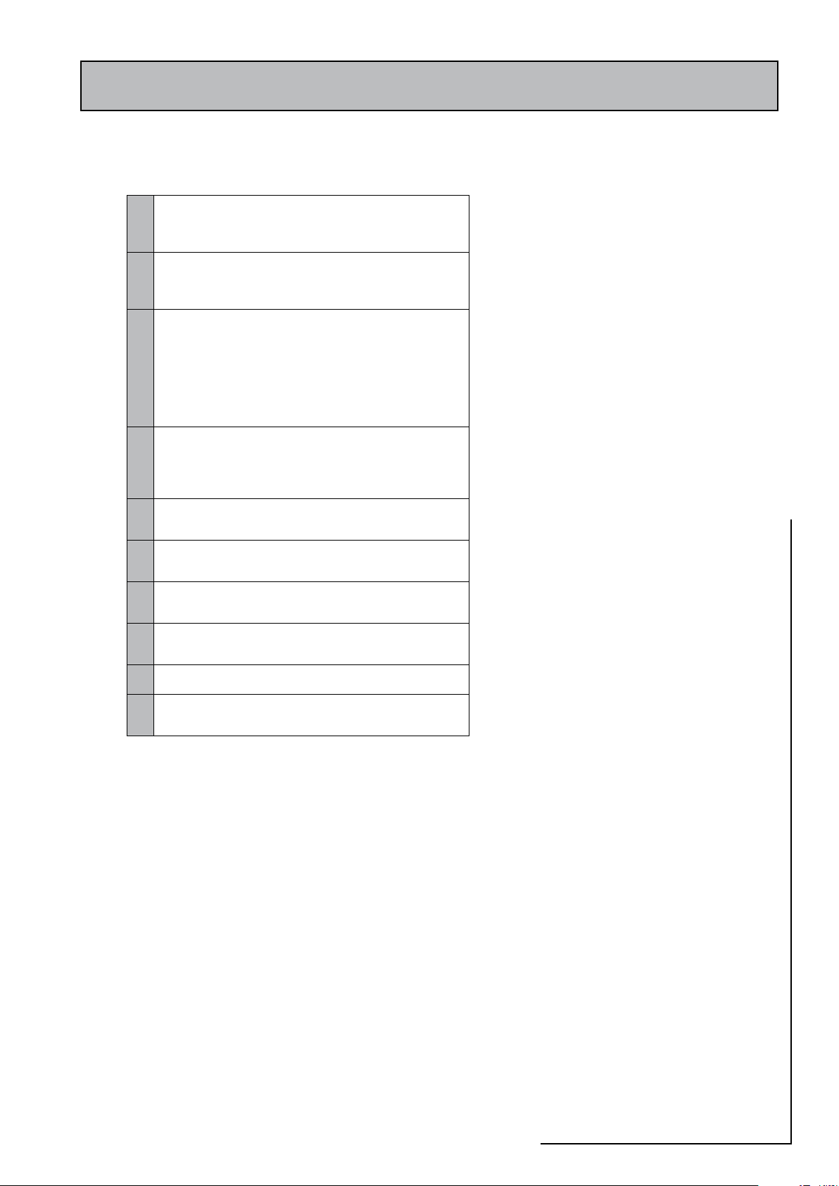
The Registered Installer is responsible for the
safe installation and operation of the system.
He must also make his customer aware that
periodic checks of the equipment are required
by the Building Regulations and essential for
safety.
Maintenance and inspection periods will vary
for many reasons. Gledhill Water Storage
Ltd recommend a maximum of 12 months
between inspections to coincide with boiler
maintenance. Experi ence of local wate r
conditions may indicate that more frequent
inspection is desirable, eg. when water is
particularly hard, scale-forming or where the
water supply contains a high proportion of
solids, eg. sand. For Maintenance see the table
opposite:
3.2 CHANGING COMPONENTS
The KIWA Approvals for the Accolade 2000
appliance are conditional on the specific
manu fac turer/ type of compone nts fitted
and any replacements must be purchased
direct from Gledhill to ensure compatibility/
continued safe operation.
Page 33
Free of charge replacements for any faulty
components are available from Gledhill during
the in-warranty period (normally 12 months).
However, if any component is damaged during
installation a new replacement must be ordered
and paid for.
After this, spares can be obtained direct from
Gledhill using the ‘Speed Spares’ service, or
through any of the larger plumbers merchants/
specialist heating spares suppliers.
Help and advice is also available from the
Technical Helpline on 08449 310000.
However, all components are readily accessible
and can be changed quickly and easily by the
installer using common plumbing practice.
If it is necessary to replace any of the pumps
fitted to the appliance the pump head (motor
pack) only should be removed as recommended
by Grundfos. Assuming it is within warranty
this will be accepted by a merchant as being
covered by the Grundfos national ser vice
exchange agreement, as long as it is a complete
pump i.e. alleged faulty motor pack and new
base is left with the merchant. It is important
when a pump has been replaced to ensure that
any air is adequately vented.
2000
ACCOLADE
Page 34
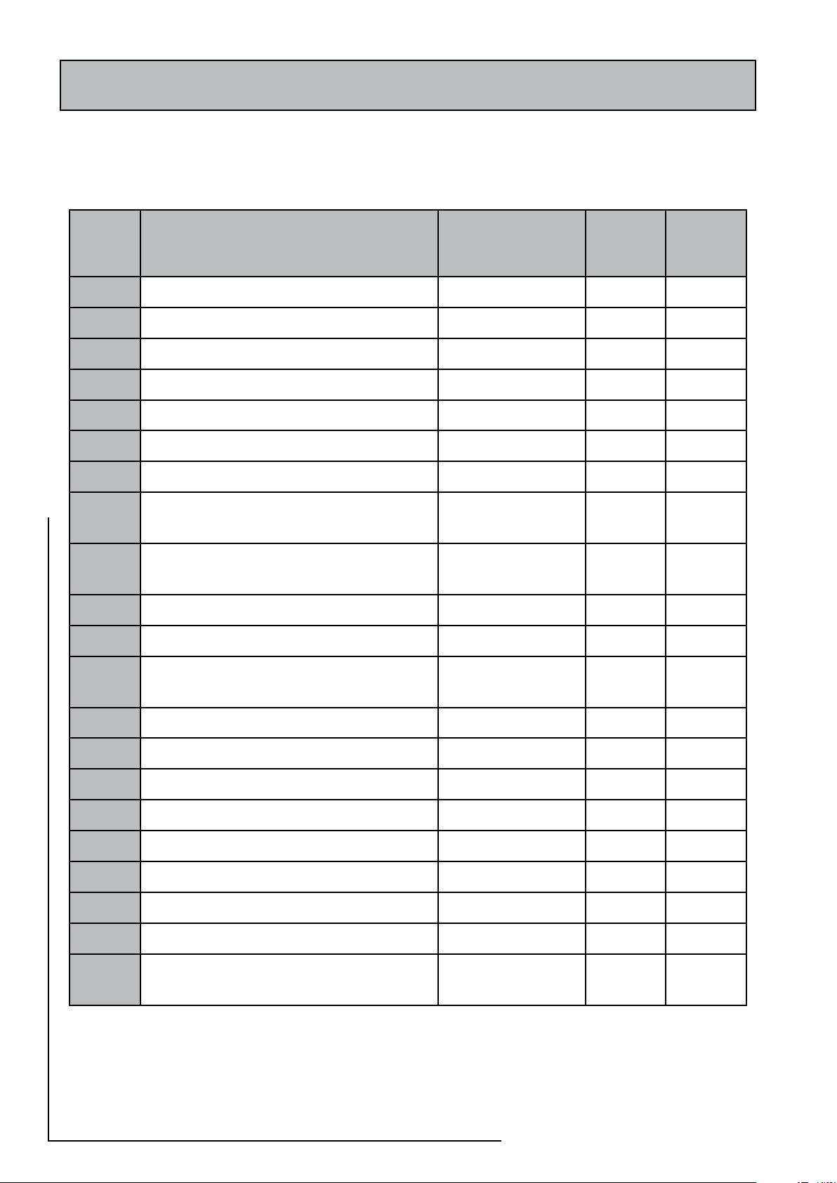
3.0 SERVICING
.oNyeK noitpircseD rerutcafunaM
kcotS
.oNedoC
saG
licnuoC
.oNtraP
1
SCIpuorGlortnoCtelnI llewyenoH
2
Cº09dnarab0.4251PTevlaVT&P llewyenoH
3
hsidnuT
4
tatsomrehTtimiLhgiH/lortnoC llewyenoH
5
tsomrehTlortnoC llewyenoH
6
1THOerotS llewyenoH
7
2THOerotS
8
3404Vmm22evlaVenoZretaWtoH
daehelbavomerhtiw
llewyenoH
9
3404Vmm82evlaVenoZretaWtoH
daehelbavomerhtiw
llewyenoH
01
evlaVssap-yBcitamotuA pamoC
11
evlaVmuucaVitnA 650TG
21
ORP-ORP-ORDYHlesseVnoisnapxE
)ertil5(ralucriC
temliZ
31
)snoitcennocmm22(05-51SPUpmuP sofdnurG
41
)snoitcennocmm82(06-51SPUpmuP sofdnurG
51
)thgiartS(evlaVpmuP
61
)elgnA(evlaVpmuP
71
retaeHnoisremmI gnirdeR
81
rotcatnoC euqinacemeleT
91
hctiwSlenaP
02
lesseVnoisnapxEyramirP temliZ
12
dnaevlaVfeileRnoisnapxEyramirP
eguaGerusserP
3.3 SHORT PARTS LIST
Page 34
Page 35
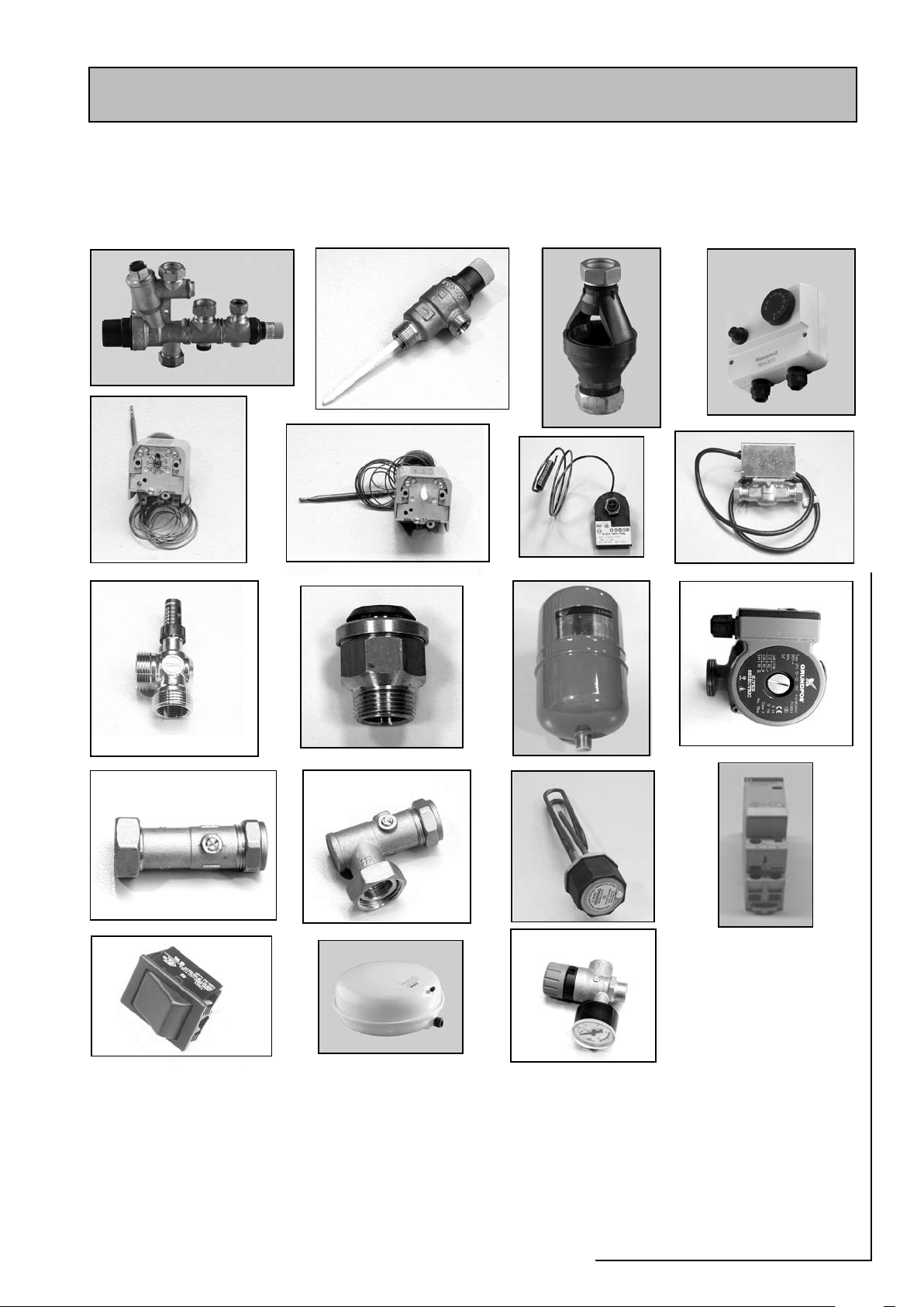
3.0 SERVICING
1
2
3
4
5
6
10
12
8/9
15
16
17
19
20
21
7
11
13/14
18
3.3 SHORT PARTS LIST
Page 35
2000
ACCOLADE
Page 36
3.0 SERVICING
12.25
Programmer
Immersion heater selected -----
Boiler energy cut-out trip ------
High limit safety trip ------
Immersion heater ---------
Normal (Boiler) ---------
Neon
Neon
Neon
Rocker
Switch
3.4 FAULT FINDING
SCALE
In hard water areas, above 200ppm (mg/l) it is recommended that an in-line scale
inhibitor is fitted. Reducing the temperature of the stored water will reduce the rate
at which scale forms. If the recovery rate is badly affected, this is an indication that
scaling may have occurred. In this event, follow the procedures as recommended by
a reputable Water Treatment Company.
GENERAL
All work must be carried out by a suitably qualified/competent person.
No hot water at the taps
Check that the mains water supply is turned ON. Check the line strainer in the
combination inlet valve is not blocked. Check that the combination valve has been
fitted so that water is flowing in the correct direction.
If the water at the tap is cold
Ensure that the boiler/immersion heater(s) have been switched ON and are working
correctly. Note: in the case of the direct units check the hot water controller/off
peak supply is working correctly. Check that there are no air locks in the primary
system. ISOLATE THE UNIT AT THE MAINS ELECTRIC SUPPLY AND THEN CHECK THE
FOLLOWING:-
i) The cylinder thermostat
ii) The thermal cut-out, which can be re-set by pushing the red button.
iii) The motorised valve
iv) The boiler thermostat
v) The boiler thermostat cut-out
If the boiler is for any reason unable to supply heat to the appliance, hot water can
be obtained by operating the rocker switch on the front of the appliance to switch
on the immersion heater.
DISCHARGE FROM RELIEF VALVES
If cold water is discharging from the expansion
relief valve drop the system pressure and check
the air pressure in the expansion vessel is 1.5
bar.
If the fault continues and the problem cannot
be stopped by operating the easing control a
few times then either the Pressure Reducing
Valve or the Relief Valve may be at fault. If
the cold water pressure is too high, this would
suggest that the Pressure Reducing Valve is at
fault and the Gledhill approved replacement
should be fitted. If the pressure is correct then
the Relief Valve/cartridge will require replacing
with a Gledhill approved component.
If there is an overheat fault and very hot water
is being discharged, turn off the heat source,
but not the water supply. When the system is
cool, check thermostats and energy cut-outs in
the boiler and immersion heaters and replace
the faulty component with a unit supplied by
Gledhill and check that it works correctly before
returning the system to full operation.
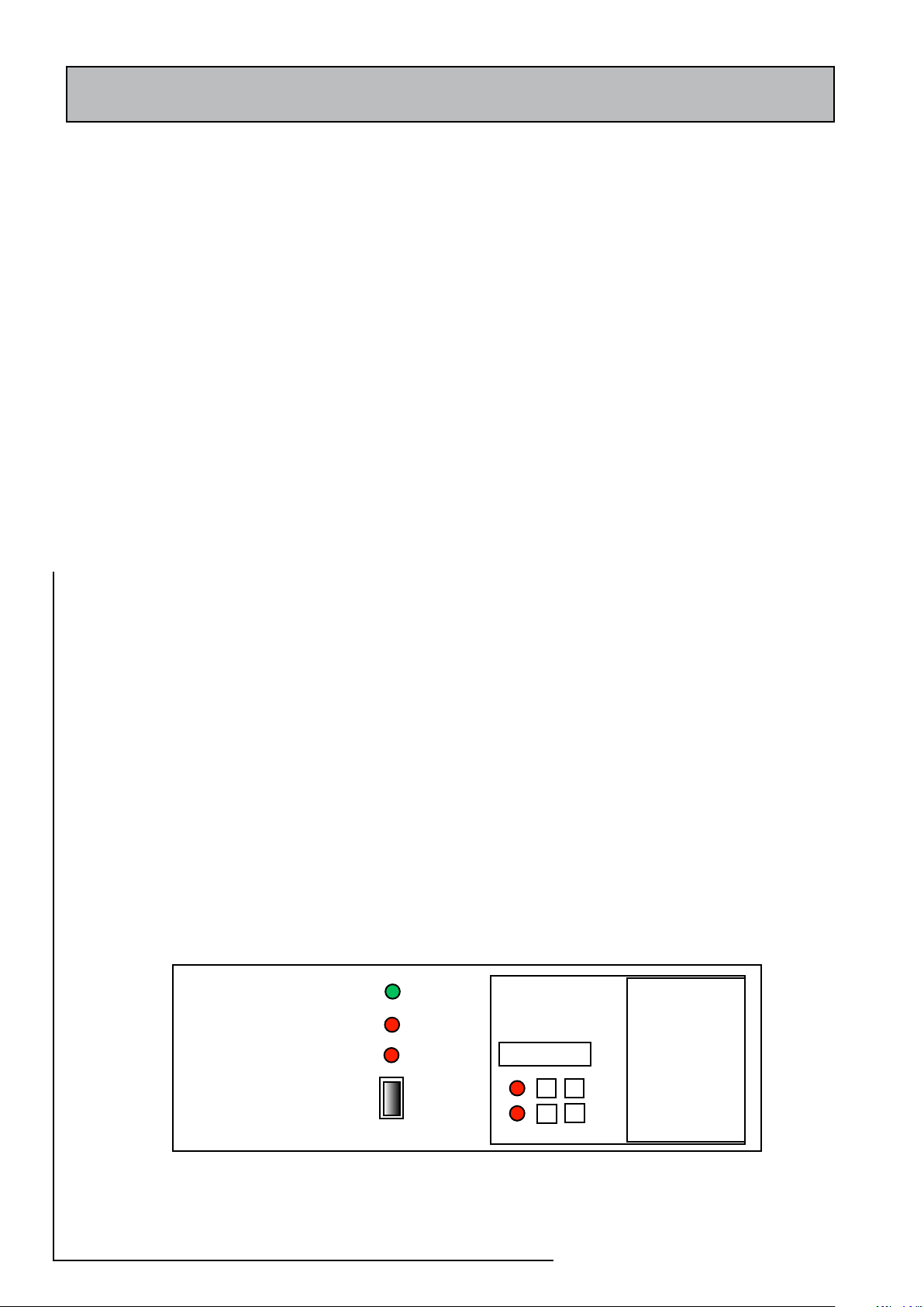
Note: The controls on the front of the indirect
unit (see below) will indicate the operating
condition of the appliance and whether either
of the two safety thermostats have tripped.
AN Y E N ER GY CU T- OU T MU ST N EV ER B E BY- PAS S ED U N DE R A NY
CIRCUMSTANCES.
If the units are not getting hot and the heat source is electrical, ensure that the
immersion heaters are isolated from the mains before re-setting the energy cut-out.
If the immersion heater(s) need replacing this should be done with the unit supplied
from Gledhill Water Storage Ltd. Same day despatch to approved installers can be
arranged by telephoning 01253 474444.
Page 36
Page 37
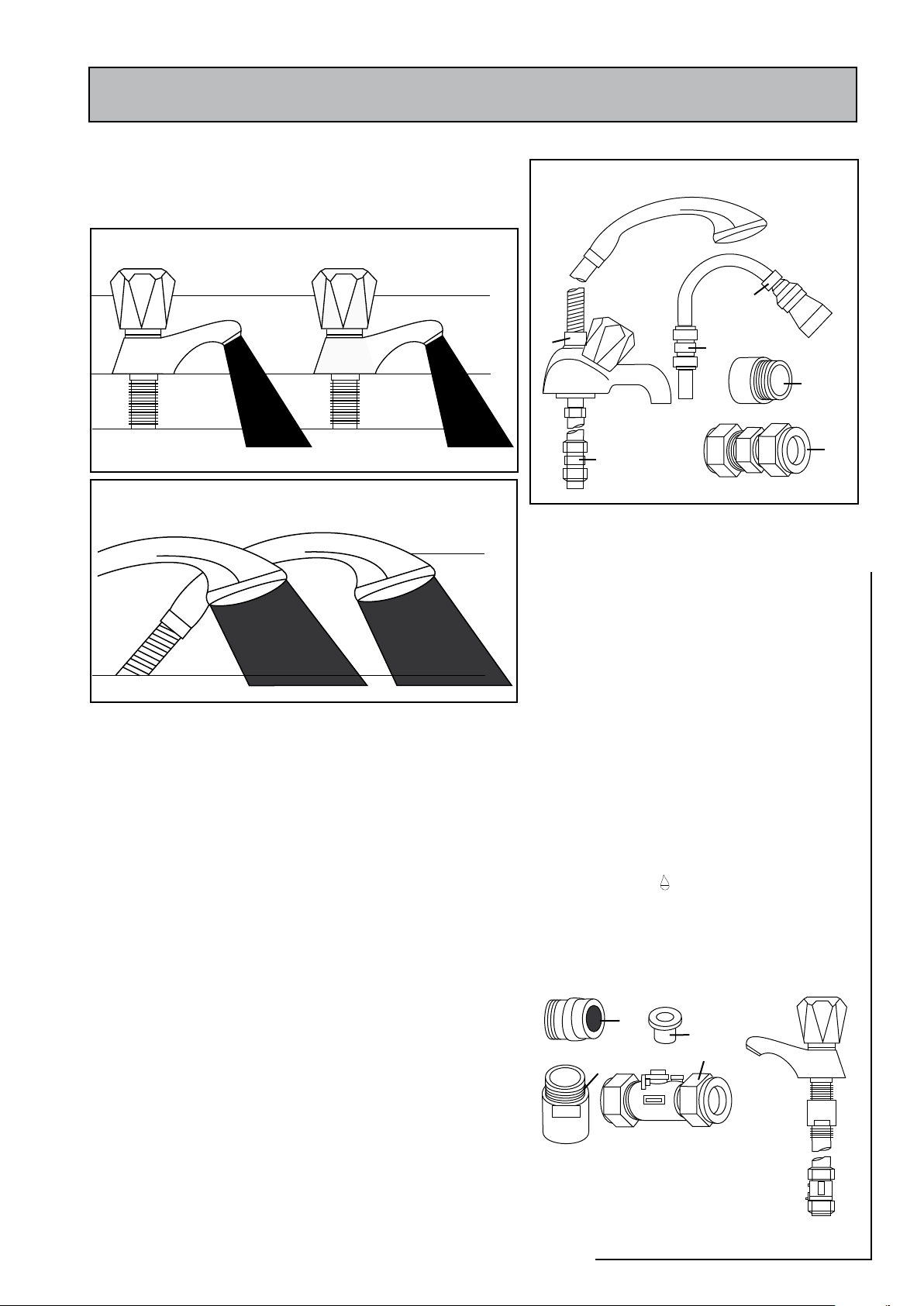
WATER SAVINGS
TAPS & MIXERS
OVER
20 L/M
5, 6 OR
8 L/M
2 TAP
HALF OPEN
Fitted with regulator
Unregulated
Unregulated
25 - 30 l/m
Regulated
10 - 12 l/m
SHOWERS
2
2
2
1
1
1
3
4
3
1
WATER RELATED COSTS CAN BE REDUCED BY GOOD
PLUMBING PRACTICE.
APPENDIX A
4 FIXING OPTIONS FOR TAPS &
Vast quantities of water are needlessly run off to waste due to
Taps, Mixers and Showers discharging flow rates far in excess of
the rates required for them to perform their duties.
The contrasting flow rates shown on this leaflet clearly illustrate
the savings that can be made whilst still providing a good
performance.
British made Aquaflow Regulators provide constant flow rates
by automatically compensating for supply pressure changes
between 1 bar & 10 bars.
To facilitate installation into the wide range of plumbing
equipment which is encountered in the U.K, Four Fixing
Options are available:-
OPTIONS FOR SHOWERS
1. MXF “DW” Range - For fitting behind Fixed Shower Heads
or onto Flexible Hoses for Handshowers (preferably onto
the inlet end when lightweight hoses are used).
2.
Compression Fitting Range. “In Line” regulators as in Option
4 for Taps & Mixers.
MIXERS
1. MK Range - Combined Regulators & Aerator
for screwing onto Taps & Mixers with internal
or external threads on their noses. Anti Vandal
models also available.
2. MR05-T Range - Internal Regulators. Push-fit
into Tap or Mixer seats. Produced in three
sizes - 12.5mm (BS1010), 12mm & 10mm,
Flangeless models also available for Taps
with Low Lift washers.
3. MXF Stand a rd R a ng e - Scre w on tai l
models for Taps & Mixers. Fix onto the tails
before fitting the tap connectors. Available in
3/8", 1/2", 3/4" and 1" BSP.
4.
Compression Fitting Range - “In Line” regulators
housed in 15mm & 22mm CXC Couplers &
Isolating Valves. “ ”UK WFBS listed by the Water
Research Centre. Isolation valves available for
slotted screwdriver operation or with coloured
plastic handles. Now available also in plastic
bodied push-fit couplers & valves.
Haywood House, 40 New Road, Stourbridge, West Midlands DY8 1PA
TELEPHONE (01384) 442611 FAX: (01384) 442612
Information by courtesy of
AQUAFLOW REGULATORS LTD
2000
ACCOLADE
Page 37
Page 38
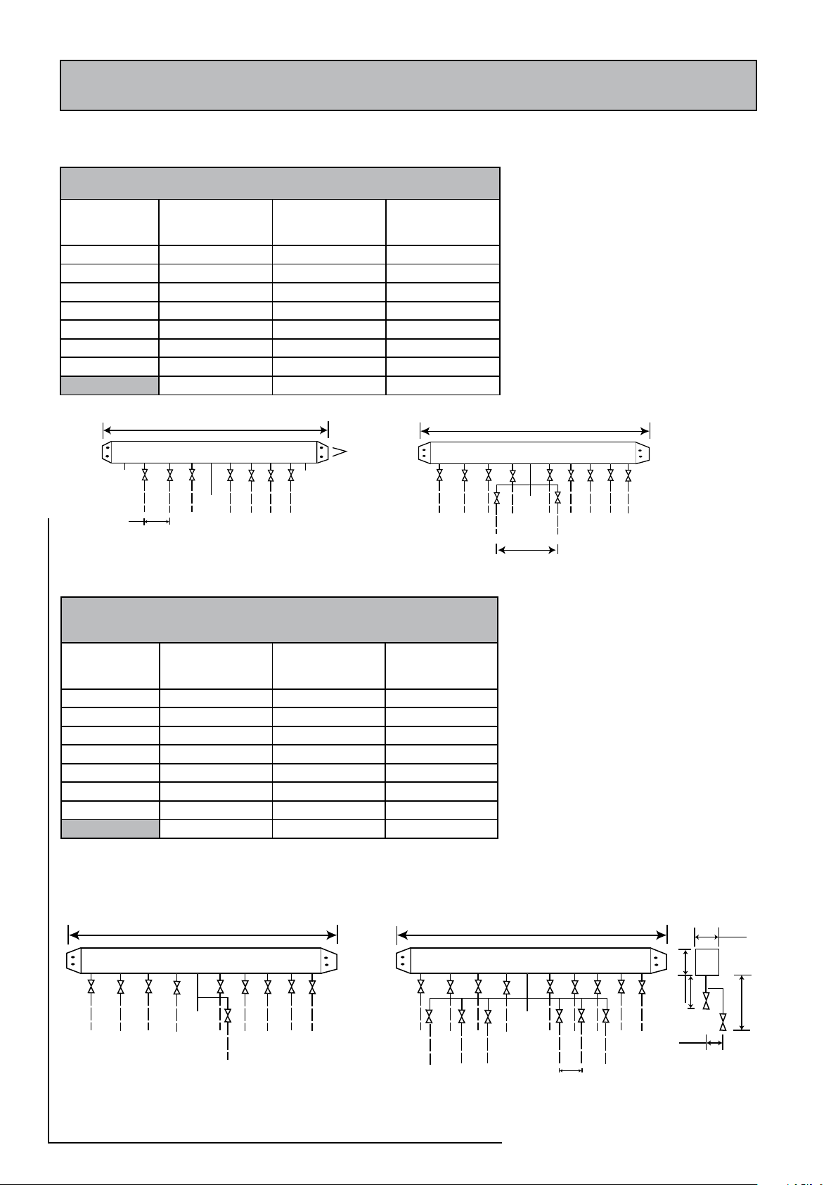
595mm
2 No 6mm
fixing holes
18 l/mm
12 l/mm
9 l/mm
9 l/mm
9 l/mm
9 l/mm
12 l/mm
inlet
55mm
18 l/mm
12 l/mm
9 l/mm
9 l/mm
9 l/mm
9 l/mm
9 l/mm
9 l/mm
9 l/mm
9 l/mm
12 l/mm
inlet
165mm
595mm
A (hot)
B (cold)
blank
blank
18 l/min
12 l/min
12 l/min
9 l/min
9 l/min
9 l/min
9 l/min
9 l/min
12 l/min
18 l/min
inlet
595mm
C
D
18 l/min
12 l/min
12 l/min
9 l/mm
9 l/mm
9 l/mm
9 l/mm
9 l/mm
9 l/mm
9 l/min
9 l/min
9 l/min
9 l/min
12 l/min
18 l/min
inlet
55mm
595mm
195 mm
90mm
85mm
85mm
90mm
(hot)
(cold)
MANIFOLDS
APPENDIX B
(one bathroom, one en suite shower room, one cloakroom, one kitchen)
Manifold type: 1 - Stock Code MIP 050
Flow regulator
(litres/minutes)
Terminal fitting Hot water manifold
outlets
Quantity
18 Bath tap 1 1
9 Hand basin 3 3
12 Kitchen sink 1 1
9 Toilet cistern None 3
9 Shower 1 1
12 Washing machine 1 1
9 Dishwasher None 1
Total 7 11
Cold water manifold
outlets
Quantity
Two sets of manifolds are available as an
optional extra. Each set comprises a separate
ho t an d co ld water mani fold. Both are
prov ided with a 22mm inlet conn ecti on
located centrally. All outlet connections are
15mm compression. The centre to centre
dimension of each branch is 55mm.
(two bathrooms, one en suite shower room, one cloakroom, one kitchen,
Manifold type: 2- Stock Code MIP 060
one utility room)
Flow regulator
(litres/minutes)
Terminal fitting Hot water manifold
outlets
Quantity
18 Bath tap 2 2
9 Hand basin 4 4
12 Kitchen sink 2 2
9 Toilet cistern None 4
9 Shower 1 1
12 Washing machine 1 1
9 Dishwasher None 1
Total 10 15
Cold water manifold
outlets
Quantity
The arrangement of each manifold is supplied
as shown. This provides the best balance of
flows but the flow regulators/duty of each
branch can be changed if required as long
as a reasonable balance is maintained. If
it is necessary to change or clean the flow
regulator this can be done without needing
to drain the system by closing the valve and
removing the screwed cover below the white
plastic cover.
The manifolds are designed to be used with
plastic pipework and are supplied complete
with isolation valves and flow regulators
on each branch. They would normally be
installed in the same cupboard as the thermal
storage appliance (as shown below) but can
be installed in another cupboard close to the
appliance if required.
Page 38
Page 39
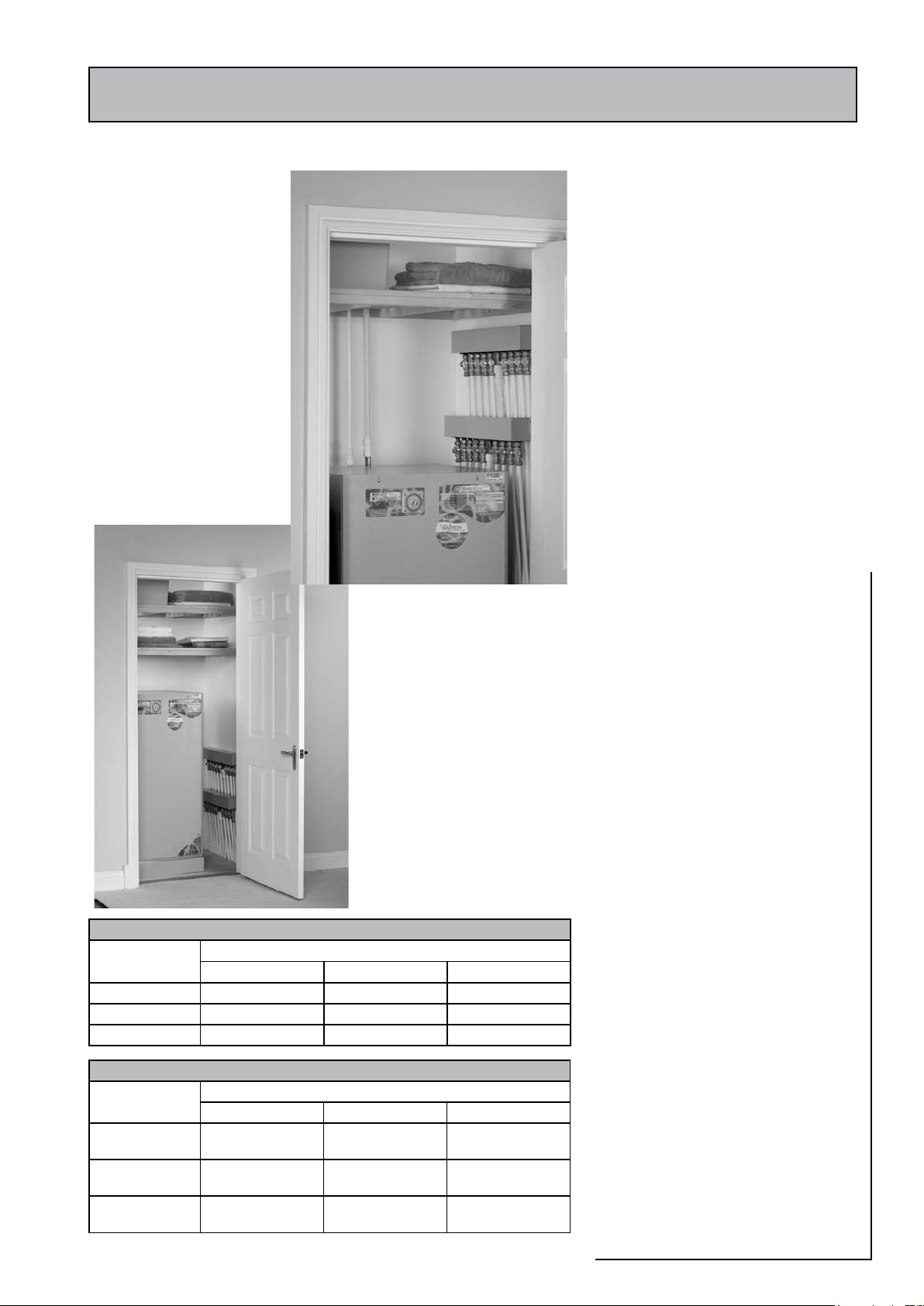
An optional location where cupboard space is tight
APPENDIX B
The pressure loss through a flow regulator
at the designated flow rate is about 1.8 bar.
Therefore for the flow regulator to control the
flow rate at pre-set level, the inlet pressure must
be greater than 1.8 bar. If the inlet pressure
is lower, the flow rate will be correspondingly
less than the pre-set values.
The maximum equivalent pipe lengths from
the manifold to the terminal fittings can be
estimated from the above information and
the resistance characteristics of the pipes.
The examples presented below are for 15mm
copper pipe in table 1 and for plastic pipework
in table 2.
The preferred solution where space will allow
Table 1: Maximum equivalent pipe length in 15mm copper
Inlet pressure
(bar)
2.0 25 10 5
2.5 75 30 15
3.0 150 60 30
Table 2: Maximum equivalent pipe length in plastic pipe
Inlet pressure
(bar)
2.0 1.5 15mm : 10 15mm : 4.5
2.5 3.0 15mm : 20 15mm : 9.0
3.0 4.5 15mm : 30 15mm 13.5
Maximum equivalent length of pipe (m)
@ 9 l/m @ 12 l/m @ 18 l/m
Maximum equivalent length of pipe (m)
@ 9 l/m @ 12 l/m @ 18 l/m
2000
22mm : 40
22mm : 80.0
22mm : 120
ACCOLADE
Page 39
Page 40
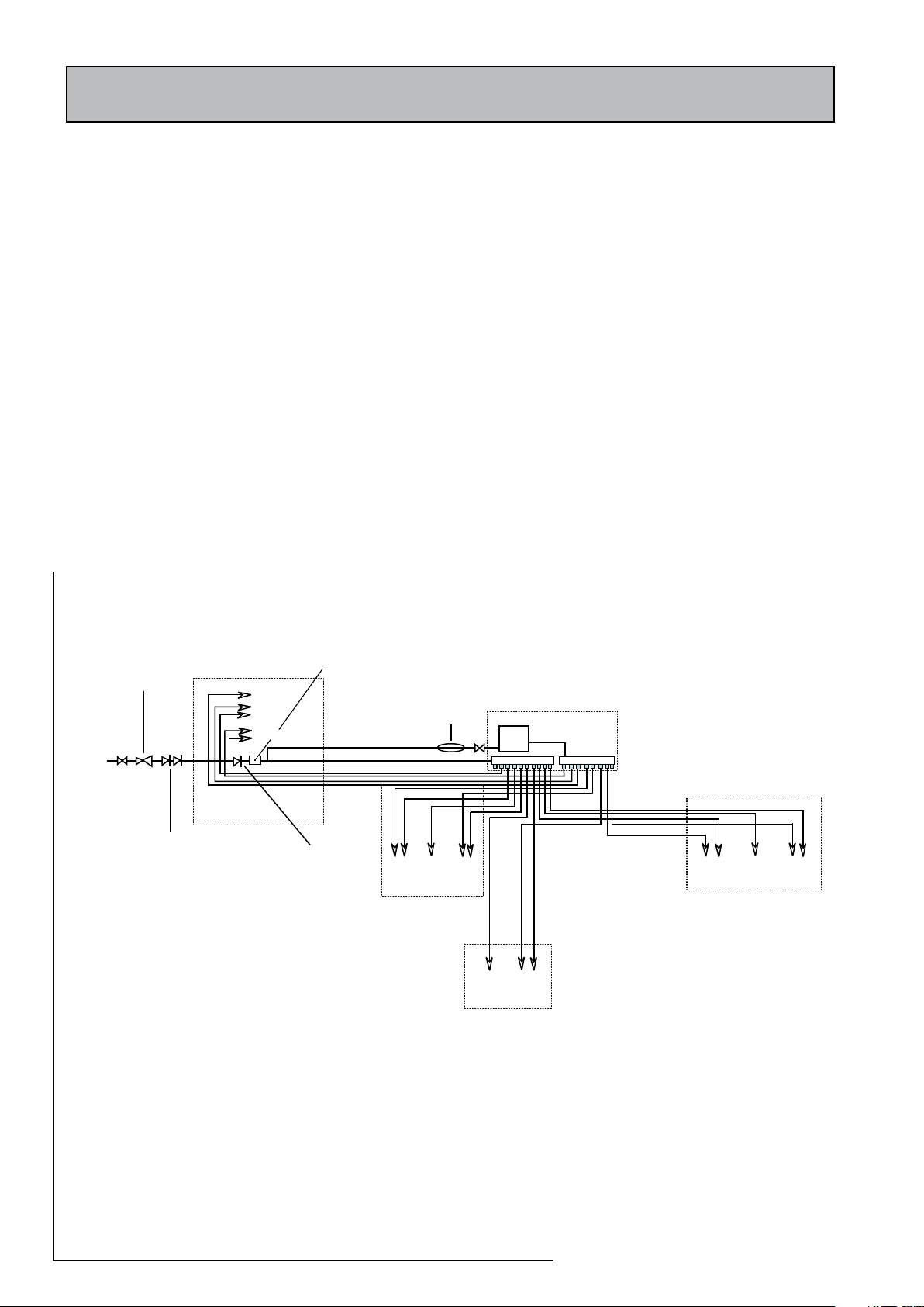
Bath Toilet
cistern
Hand
basin
Toilet
cistern
Hand
basin
Hand
basin
Toilet
cistern
Mains
supply
Shower
DW
Kitchen sink
Kitchen
En-Suite
Bathroom
Check valve
NOT REQUIRED
unless chemical
water treatment
is fitted
Double check
valve NOT REQUIRED
unless supply pipe
services more than
one dwelling
Pressure limiting valve
NOT REQUIRED at pressures
below 5 bar unless any system
components have a lower
maximum working
pressure
Cloak room
WM
Accolade 2000
Scale
inhibitor
NOT REQUIRED
Airing
cupboard
See Note 1
Gledhill (Water Storage) Ltd
AMD. JUNE 2008
CONDITIONS OF SALE & GUARANTEE TERMS
1. Gledhill (Water Storage) Ltd (“We” or “Gledhills”) only do business upon the Conditions which appear below
and no other. Unless we so agree in writing these Conditions shall apply in full to any supply of goods by us to
the exclusion of any Conditions or terms sought to be imposed by any purchaser. These Conditions of Sale and
Warranty Terms override those which are contained on the Invoice Forms and all Sales are now subject to these
Conditions of Sale and Warranty terms only.
2. PRICE
Once an order or call off has been accepted the price will be held for three months but if delivery is extended
beyond that period at the customer’s request, then we reserve the right to amend the price when necessary.
The company reviews its pricing annually to adjust for changes in our cost base. We reserve the right to alter prices
at any time for severe movements in raw materials (mainly copper and steel). If there is to be a change we will give
customers at least four weeks notice but anything delivered after that date will be at the revised price. An order
may not be cancelled or varied after acceptance without the written consent of the company. Such cancellation or
variation shall be subject to such reasonable charges as may be appropriate.
3. SPECIFICATION
The goods are supplied in accordance with the Specifications (if any) submitted to the Purchaser and any additions
and alterations shall be the subject of an extra charge. Any goods not so specified shall be in accordance with our
printed literature or the literature of any of our component suppliers (subject to any modifications made since
publication). If we adopt any changes in construction or design of the goods, or in the specification printed in our
literature, the Purchaser shall accept the goods so changed in fulfilment of the order.
4. PAYMENT
The invoice price of goods shall be payable within 30 days of despatch by us of our invoice for the goods or such
longer time as may be stated by our quotation or invoice. If we receive payment in full on or before the due date we
will allow an appropriate settlement discount except where we have quoted a special net price. If payment is not
received in full on or before the due date we shall be entitled in addition to the invoice price to:
(i) payment of a sum equal to any increase in the copper price supplement applicable to the particular goods
sold between the date of receipt of order and the date of receipt of payment in full; and
(ii) interest on any part of the invoice price unpaid after the due date at the rate of 3% per annum over the base
rate for the time being of HSBC Bank plc.
5. TIME
We give estimates of delivery dates in good faith and time of delivery is not nor shall be made of the essence of any
contract nor shall we be liable for any loss or damage occasioned by delay in delivery.
6. DELIVERY
We deliver free normally by our own vehicles within 25 miles of any of our manufacturing depots. Delivery to any
place more than 25 miles from one of our manufacturing depots may be subject to our quoted delivery charges. We
reserve the right to make delivery of goods contained in one order by more than one consignment and at different
times. Where a period is agreed for delivery and such period is not extended by our Agreement, the Purchaser shall
take delivery within that period. If the Purchaser fails to take delivery, we shall be entitled at the Purchaser’s risk and
expense to store the goods at the Purchaser’s premises or elsewhere and to demand payment as if they had been
despatched. Off loading at point of delivery shall be the responsibility of and be undertaken by the Purchaser.
7. SHORTAGES OR DAMAGE
Goods must be inspected before signature of delivery note and any damage, shortage or discrepancy noted on the
delivery note and the goods returned on the same vehicle. The buyer must also give us immediate written notice of
the damage, shortage or discrepancy so that we may prompt investigation.
8. RETURN OF GOODS
Goods may not be returned to the Company except by prior written permission of an authorised officer of the
Company and such return shall be subject to payment by the Purchaser of handling and re-stocking charges,
transport and all other costs incurred by the Company.
9. COMPANY LIABILITY AND GUARANTEE
9.1. Subject to the terms of these Conditions of Sale and Guarantee Terms Gledhills provide Guarantees in respect
of specific products as set out in this clause.
9.2. Each Guarantee is strictly conditional upon the following:-
9.2.1. Complaints must be given to us immediately, before any action is taken, as responsibility cannot be accepted
if repairs or renewals are attempted on site without our written approval.
9.2.2. The unit has been installed in accordance with our installation and service instructions and all relevant codes
of practice and regulations in force at the time of installation.
9.2.3. All necessary inlet controls and safety valves have been fitted correctly.
9.2.4. The unit has only been used for the storage of potable water supplied from the public mains.
9.2.5 Where appropriate the unit has been regularly maintained as detailed in the installation and service
instructions
9.2.6. Defects caused by corrosion or scale deposits are not covered by any Guarantee.
9.2.7. Where we agree to rectify any defect we reserve the right to undertake the work on our own premises.
9.3. Guarantees are provided in respect of specified goods supplied by Gledhills as follows:-
(a) Domestic and Commercial Open Vented Cylinders and Tanks.
The copper storage vessel is guaranteed for ten years and if it proves to be defective either in materials or
workmanship, we will either repair or supply replacement at our option with the closest substitute in the case
of any obsolete product to any address in Great Britain.
(i) free of all charge during the first year after delivery by us.
(ii) thereafter at a charge of one-tenth of the then current list price and any copper price supplement and
delivery charge during the second year after delivery by us and increasing by a further one-tenth on the
second and subsequent anniversary of delivery by us.
(b) Domestic Mains Fed Products [Primary Stores]
The copper storage vessel is guaranteed for five years and if it or any integral pipework as part of the storage
vessel assembly proves to be defective either in materials or workmanship, we reserve the right to either
repair or supply replacements or the closest possible substitute in the case of any obsolete product and will
collect and deliver to any address in England, Wales and Scotland (excluding all Scottish Islands).
(i) free of all charge during the first year after delivery by us.
(ii) thereafter at a charge of one-fifth of the then current list price or any copper price supplement and
delivery charge during the second year after delivery by us increasing by a further one-fifth on the second
and subsequent anniversary of delivery by us.
(c) Integrated Boiler and Storage Vessel Products and Stand Alone Boilers
In the case of the GulfStream range of products and the Gledhill boiler range of products, Gledhill guarantees
the heat exchanger (boiler) for material and construction faults for two years. THE RESPONSIBILITY FOR THE
EXECUTION OF THIS GUARANTEE LIES WITH THE INSTALLER.
The guarantee becomes null and void if the appliance is used incorrectly, or in the event of proven negligence
or incorrectly implemented repairs OR FAILURE TO CARRY OUT THE RECOMMENDED INSPECTION/
MAINTENANCE. The guarantee also becomes null and void if changes are made to the appliance without our
knowledge, or if the serial number on the appliance is removed or made illegible.
The annual service must be carried out by a competent
installer in accordance with the advice given by
Gledhill and using Gledhill approved parts.
(d) Stainless Steel Unvented Cylinders
Gledhill guarantee the components including controls,
valves and electrical parts for two years from the date
of purchase. IT SHOULD BE NOTED THAT THE FACTORY
FITTED TEMPERATURE AND PRESSURE RELIEF VALVE
MUST NOT BE REMOVED OR ALTERED IN ANY WAY
OR THE GUARANTEE WILL NOT BE VALID. GLEDHILL
WILL NOT BE RESPONSIBLE FOR ANY CONSEQUENTIAL
LOSS OR DAMAGE HOWEVER IT IS CAUSED.
The guarantee for the stainless steel vessel is for
twenty five years if the original unit is returned to us
AND PROVIDED THAT:
(i) It has been installed as per the Design, Installation
& Servicing Instructions, relevant standards,
regulations and codes of practice.
(ii) It has not been modified, other than by Gledhill.
(iii) It has not been subjected to wrong or improper
use or left uncared for.
(iv) It has only been used for the storage of potable
water.
(v) It has not been subjected to frost damage.
(vi) The benchmark log book is completed after each
annual service.
(vii) The unit has been serviced annually.
It should be noted that the guarantee does not cover:
- the effects of scale build up
- any labour charges associated with replacing the
unit or parts.
If the stainless steel vessel proves to be defective
either in materials or workmanship we reserve the
right to either repair or supply replacements or the
closest possible substitute in the case of any obsolete
product and will collect and deliver to any address in
England, Scotland and Wales (excluding all islands):
(i)
free of charge during the first year after delivery by us.
(ii) thereafter at a charge of one twenty fifth of the
then current list price during the second year
after delivery by us and increasing by a further
one twenty fifth on the second and subsequent
anniversary of delivery by us.
ACTION IN THE EVENT OF FAILURE
If the stainless steel cylinder develops a leak we will
ask for a deposit against the supply of a new one. This
will be refunded if the failure is within the terms of the
warranty when it has been examined by us.
(e) Solar Panels and ancillary equipment
Gledhill provides a five year warranty for defects in
the collectors (except broken glass and collector
accessories eg metal edgings). If the collector
demonstrably fails to meet one of the requirements of
the standard DIN 4757 part 3 we will replace it free of
charge based on the date of invoice. We can not be
responsible for damage caused by mechanical stress
and/or changes caused by weather related influences.
The warranty excludes minor surface damage that
does not affect performance or malfunction due to
improper assembly or installation.
Please note:
- Installation must have been carried out by a
licensed specialized company (heating contractor
or plumber) following the version of installation
instructions in force.
- Gledhill or its representative was given the
opportunity to check complaints on site
immediately after any defect occurred.
- Confirmation exists that the system was
commissioned properly and that the system
was checked and maintenance was performed
annually by a specialised company licensed for
this purpose.
(f) Components of our products other than
Storage Vessels and Integral Pipework.
We will either extend to the purchaser the same terms
of warranty as we are given by the manufacturer of
the component or if the manufacturer does not give
any warranty, replace free of charge any component
which becomes defective within two years after the
date of the delivery by us and is returned to us at the
purchaser’s expense but we shall not meet the cost of
removal or shipping or return of the component or
any other cost charges or damages incurred by the
purchaser.
If the appliance manufactured by Gledhill incorporates
a factory fitted scale inhibitor then during the period
APPENDIX B
The size of the distribution pipes supplying
the manifold should be calculated using
the method set out in BS 6700. A typical
di agra mmati c ar range ment of a system
us i ng Man i fold Type 1 is sh own be l ow.
This is only meant to show the principles
in volved a nd t h e ac t ual connec tion o f
fittings to the manifold will need to suit the
arrangements shown on page 35.
Note 1 - If it is proposed to fit chemical water
treatment such as a water softener this should
be fitted in this location and the cold water
branch in the sink should be branched off the
cold water main prior to the treatment device
instead of the cold water manifold.
An y other isola tin g / control va l ves and
ba c kflow p rotec tio n devices should be
provided as necessary to comply with the
Water Regulations.
Page 40
Page 41

Gledhill (Water Storage) Ltd
AMD. JUNE 2008
CONDITIONS OF SALE & GUARANTEE TERMS
1. Gledhill (Water Storage) Ltd (“We” or “Gledhills”) only do business upon the Conditions which appear below
and no other. Unless we so agree in writing these Conditions shall apply in full to any supply of goods by us to
the exclusion of any Conditions or terms sought to be imposed by any purchaser. These Conditions of Sale and
Warranty Terms override those which are contained on the Invoice Forms and all Sales are now subject to these
Conditions of Sale and Warranty terms only.
2. PRICE
Once an order or call off has been accepted the price will be held for three months but if delivery is extended
beyond that period at the customer’s request, then we reserve the right to amend the price when necessary.
The company reviews its pricing annually to adjust for changes in our cost base. We reserve the right to alter prices
at any time for severe movements in raw materials (mainly copper and steel). If there is to be a change we will give
customers at least four weeks notice but anything delivered after that date will be at the revised price. An order
may not be cancelled or varied after acceptance without the written consent of the company. Such cancellation or
variation shall be subject to such reasonable charges as may be appropriate.
3. SPECIFICATION
The goods are supplied in accordance with the Specifications (if any) submitted to the Purchaser and any additions
and alterations shall be the subject of an extra charge. Any goods not so specified shall be in accordance with our
printed literature or the literature of any of our component suppliers (subject to any modifications made since
publication). If we adopt any changes in construction or design of the goods, or in the specification printed in our
literature, the Purchaser shall accept the goods so changed in fulfilment of the order.
4. PAYMENT
The invoice price of goods shall be payable within 30 days of despatch by us of our invoice for the goods or such
longer time as may be stated by our quotation or invoice. If we receive payment in full on or before the due date we
will allow an appropriate settlement discount except where we have quoted a special net price. If payment is not
received in full on or before the due date we shall be entitled in addition to the invoice price to:
(i) payment of a sum equal to any increase in the copper price supplement applicable to the particular goods
sold between the date of receipt of order and the date of receipt of payment in full; and
(ii) interest on any part of the invoice price unpaid after the due date at the rate of 3% per annum over the base
rate for the time being of HSBC Bank plc.
5. TIME
We give estimates of delivery dates in good faith and time of delivery is not nor shall be made of the essence of any
contract nor shall we be liable for any loss or damage occasioned by delay in delivery.
6. DELIVERY
We deliver free normally by our own vehicles within 25 miles of any of our manufacturing depots. Delivery to any
place more than 25 miles from one of our manufacturing depots may be subject to our quoted delivery charges. We
reserve the right to make delivery of goods contained in one order by more than one consignment and at different
times. Where a period is agreed for delivery and such period is not extended by our Agreement, the Purchaser shall
take delivery within that period. If the Purchaser fails to take delivery, we shall be entitled at the Purchaser’s risk and
expense to store the goods at the Purchaser’s premises or elsewhere and to demand payment as if they had been
despatched. Off loading at point of delivery shall be the responsibility of and be undertaken by the Purchaser.
7. SHORTAGES OR DAMAGE
Goods must be inspected before signature of delivery note and any damage, shortage or discrepancy noted on the
delivery note and the goods returned on the same vehicle. The buyer must also give us immediate written notice of
the damage, shortage or discrepancy so that we may prompt investigation.
8. RETURN OF GOODS
Goods may not be returned to the Company except by prior written permission of an authorised officer of the
Company and such return shall be subject to payment by the Purchaser of handling and re-stocking charges,
transport and all other costs incurred by the Company.
9. COMPANY LIABILITY AND GUARANTEE
9.1. Subject to the terms of these Conditions of Sale and Guarantee Terms Gledhills provide Guarantees in respect
of specific products as set out in this clause.
9.2. Each Guarantee is strictly conditional upon the following:-
9.2.1. Complaints must be given to us immediately, before any action is taken, as responsibility cannot be accepted
if repairs or renewals are attempted on site without our written approval.
9.2.2. The unit has been installed in accordance with our installation and service instructions and all relevant codes
of practice and regulations in force at the time of installation.
9.2.3. All necessary inlet controls and safety valves have been fitted correctly.
9.2.4. The unit has only been used for the storage of potable water supplied from the public mains.
9.2.5 Where appropriate the unit has been regularly maintained as detailed in the installation and service
instructions
9.2.6. Defects caused by corrosion or scale deposits are not covered by any Guarantee.
9.2.7. Where we agree to rectify any defect we reserve the right to undertake the work on our own premises.
9.3. Guarantees are provided in respect of specified goods supplied by Gledhills as follows:-
(a) Domestic and Commercial Open Vented Cylinders and Tanks.
The copper storage vessel is guaranteed for ten years and if it proves to be defective either in materials or
workmanship, we will either repair or supply replacement at our option with the closest substitute in the case
of any obsolete product to any address in Great Britain.
(i) free of all charge during the first year after delivery by us.
(ii) thereafter at a charge of one-tenth of the then current list price and any copper price supplement and
delivery charge during the second year after delivery by us and increasing by a further one-tenth on the
second and subsequent anniversary of delivery by us.
(b) Domestic Mains Fed Products [Primary Stores]
The copper storage vessel is guaranteed for five years and if it or any integral pipework as part of the storage
vessel assembly proves to be defective either in materials or workmanship, we reserve the right to either
repair or supply replacements or the closest possible substitute in the case of any obsolete product and will
collect and deliver to any address in England, Wales and Scotland (excluding all Scottish Islands).
(i) free of all charge during the first year after delivery by us.
(ii) thereafter at a charge of one-fifth of the then current list price or any copper price supplement and
delivery charge during the second year after delivery by us increasing by a further one-fifth on the second
and subsequent anniversary of delivery by us.
(c) Integrated Boiler and Storage Vessel Products and Stand Alone Boilers
In the case of the GulfStream range of products and the Gledhill boiler range of products, Gledhill guarantees
the heat exchanger (boiler) for material and construction faults for two years. THE RESPONSIBILITY FOR THE
EXECUTION OF THIS GUARANTEE LIES WITH THE INSTALLER.
The guarantee becomes null and void if the appliance is used incorrectly, or in the event of proven negligence
or incorrectly implemented repairs OR FAILURE TO CARRY OUT THE RECOMMENDED INSPECTION/
MAINTENANCE. The guarantee also becomes null and void if changes are made to the appliance without our
knowledge, or if the serial number on the appliance is removed or made illegible.
The annual service must be carried out by a competent
installer in accordance with the advice given by
Gledhill and using Gledhill approved parts.
(d) Stainless Steel Unvented Cylinders
Gledhill guarantee the components including controls,
valves and electrical parts for two years from the date
of purchase. IT SHOULD BE NOTED THAT THE FACTORY
FITTED TEMPERATURE AND PRESSURE RELIEF VALVE
MUST NOT BE REMOVED OR ALTERED IN ANY WAY
OR THE GUARANTEE WILL NOT BE VALID. GLEDHILL
WILL NOT BE RESPONSIBLE FOR ANY CONSEQUENTIAL
LOSS OR DAMAGE HOWEVER IT IS CAUSED.
The guarantee for the stainless steel vessel is for
twenty five years if the original unit is returned to us
AND PROVIDED THAT:
(i) It has been installed as per the Design, Installation
& Servicing Instructions, relevant standards,
regulations and codes of practice.
(ii) It has not been modified, other than by Gledhill.
(iii) It has not been subjected to wrong or improper
use or left uncared for.
(iv) It has only been used for the storage of potable
water.
(v) It has not been subjected to frost damage.
(vi) The benchmark log book is completed after each
annual service.
(vii) The unit has been serviced annually.
It should be noted that the guarantee does not cover:
- the effects of scale build up
- any labour charges associated with replacing the
unit or parts.
If the stainless steel vessel proves to be defective
either in materials or workmanship we reserve the
right to either repair or supply replacements or the
closest possible substitute in the case of any obsolete
product and will collect and deliver to any address in
England, Scotland and Wales (excluding all islands):
(i)
free of charge during the first year after delivery by us.
(ii) thereafter at a charge of one twenty fifth of the
then current list price during the second year
after delivery by us and increasing by a further
one twenty fifth on the second and subsequent
anniversary of delivery by us.
ACTION IN THE EVENT OF FAILURE
If the stainless steel cylinder develops a leak we will
ask for a deposit against the supply of a new one. This
will be refunded if the failure is within the terms of the
warranty when it has been examined by us.
(e) Solar Panels and ancillary equipment
Gledhill provides a five year warranty for defects in
the collectors (except broken glass and collector
accessories eg metal edgings). If the collector
demonstrably fails to meet one of the requirements of
the standard DIN 4757 part 3 we will replace it free of
charge based on the date of invoice. We can not be
responsible for damage caused by mechanical stress
and/or changes caused by weather related influences.
The warranty excludes minor surface damage that
does not affect performance or malfunction due to
improper assembly or installation.
Please note:
- Installation must have been carried out by a
licensed specialized company (heating contractor
or plumber) following the version of installation
instructions in force.
- Gledhill or its representative was given the
opportunity to check complaints on site
immediately after any defect occurred.
- Confirmation exists that the system was
commissioned properly and that the system
was checked and maintenance was performed
annually by a specialised company licensed for
this purpose.
(f) Components of our products other than
Storage Vessels and Integral Pipework.
We will either extend to the purchaser the same terms
of warranty as we are given by the manufacturer of
the component or if the manufacturer does not give
any warranty, replace free of charge any component
which becomes defective within two years after the
date of the delivery by us and is returned to us at the
purchaser’s expense but we shall not meet the cost of
removal or shipping or return of the component or
any other cost charges or damages incurred by the
purchaser.
If the appliance manufactured by Gledhill incorporates
a factory fitted scale inhibitor then during the period
Page 41
2000
ACCOLADE
Page 42

of three years from the date of delivery Gledhill will replace, free of charge, any plate heat exchanger fitted in
the appliance as original equipment in which scale formation occurs that materially reduces the effectiveness
of the plate heat exchanger. This guarantee does not extend to any other component installed within the
Gledhill appliance or elsewhere in the Purchasers domestic water system.
9.4.
9.4.1. In respect of goods supplied by us and in respect of any installation work carried out by or on our behalf, our
entire liability and the purchaser’s sole remedies (subject to the Guarantees) shall be as follows:(a) We accept liability for death or personal injury to the extent that it results from our negligence or that of
our employees
(b) Subject to the other provisions of this clause 9 we accept liability for direct physical damage to tangible
property to the extent that such damage is caused by our negligence or that of our employees, agents or
subcontractors.
(c) Our total liability to the purchaser over and above any liability to replace under the Guarantees (whether
in contract or in tort including negligence) in respect of any one cause of loss or damage claimed to result
from any breach of our obligations hereunder, shall be limited to actual money damages which shall not
exceed £20,000 provided that such monetary limit shall not apply to any liability on the part of ourselves
referred to in paragraph (a) above
(d) Except as provided in paragraph (a) above but otherwise not withstanding any provision herein contained
in no event shall we be liable for the following loss or damage howsoever caused and even if foreseeable
by us or in our contemplation: (i) economic loss which shall include loss of profits, business revenue, goodwill or anticipated savings
(ii) damages in respect of special indirect or consequential loss or damage (other than death, personal
injury and damage to tangible property)
(iii) any claim made against the purchaser by any other party (save as expressly provided in paragraph (b)
above)
(e) Except in respect of our liability referred to in paragraph (a) above no claim may be made or action
brought (whether in contract or in tort including negligence) by the purchaser in respect of any goods
supplied by us more than one year after the date of the invoice for the relevant goods.
(f) Without prejudice to any other term we shall not be liable for any water damage caused directly or
indirectly as a result of any leak or other defect in the goods. We cannot control the conditions of use of
the goods or the time or manner or location in which they will be installed and the purchaser agrees to
be fully responsible for testing and checking all works which include the goods at all relevant times (up
to, including and after commissioning) and for taking all necessary steps to identify any leaks and prevent
any damage being caused thereby.
(g) Nothing in these Conditions shall confer on the purchaser any rights or remedies to which the purchaser
would not otherwise be legally entitled
10. LOSS OR INJURY
Notwithstanding any other provision contained herein the purchaser’s hereby agree to fully indemnify us against
any damages losses costs claims or expenses incurred by us in respect of any claim brought against us by any third
party for:(a) any loss injury or damage wholly or partly caused by any goods supplied by us or their use.
(b) any loss injury or damage wholly or partly caused by the defective installation or substandard workmanship
or materials used in the installation of any goods supplied by us.
(c) any loss injury or damage in any way connected with the performance of this contract.
(d) any loss resulting from any failure by the purchaser to comply with its obligations under these terms as to
install and/or check works correctly.
PROVIDED that this paragraph will not require the purchaser to indemnify us against any liability for our own acts
of negligence or those of our employees agents or sub-contractors
FURTHER in the case of goods supplied by us which are re-sold and installed by a third party by the purchaser it will
be the sole responsibility of the purchaser to test the goods immediately after their installation to ensure that inter
alia they are correctly installed and in proper working order free from leaks and are not likely to cause any loss injury
or damage to any person or property.
11. VARIATION OF WARRANTY AND EXCLUSION
Should our warranty and exclusion be unacceptable we are prepared to negotiate for variation in their terms but
only on the basis of an increase in the price to allow for any additional liability or risk which may result from the
variation.
Purchasers are advised to insure against any risk or liability which they may incur and which is not covered by our
warranty.
12. RISK AND RETENTION OF TITLE
(a) goods supplied by us shall be at the Purchaser’s risk immediately upon delivery to the Purchaser or into
custody on the Purchaser’s behalf or to the Purchaser’s Order. The Purchaser shall effect adequate insurance
of the goods against all risks to the full invoice value of the goods, such insurance to be effective from the time
of delivery until property in the goods shall pass to the Purchaser as hereinafter provided.
(b) property in the goods supplied hereunder will pass to the Purchaser when full payment has been made by the
Purchaser to us for :-
(i) the goods of the subject of this contract.
(ii) all other goods the subject to of any other contract between the Purchaser and us which, at the time of
payment of the full price of the goods sold under this contract, have been delivered to the Purchaser but
not paid for in full.
(c) until property in the goods supplied hereunder passes to the Purchaser in accordance with paragraph (2)
above.
(i) the Purchaser shall hold the goods in a fiduciary capacity for us and shall store the same separately from
any other goods in the Purchaser’s possession and in a manner which enables them to be identified as our
goods.
(ii) the Purchaser shall immediately return the goods to us should our authorised representative so request.
All the necessary incidents associated with a fiduciary relationship shall apply.
(d) the Purchaser’s right to possess the goods shall cease forthwith upon the happening of any of the following
events, namely :-
(i) if the Purchaser fails to make payment in full for the goods within the time stipulated in clause 4 hereof.
(ii) if the Purchaser, not being a company, commits any act of bankruptcy, makes a proposal to his or her
creditors for a compromise or does anything which would entitle a petition for a Bankruptcy Order to be
presented.
(iii) if the Purchaser, being a company, does anything or fails to do anything which would entitle an
administrator or an administrative receiver or a receiver to take possession of any assets or which would
entitle any person to present a petition for winding up or to apply for an administration order.
(e) the Purchaser hereby grants to us an irrevocable licence to enter at any time any vehicle or premises owned
or occupied by the Purchaser or in the possession of the Purchaser for the purposes of repossessing and
recovering any such goods the property in which
has remained in us under paragraph (2) above. We
shall not be responsible for and the Purchaser will
indemnify us against liability in respect of damage
caused to any vehicle or premises in such repossession
and removal being damaged which it was not
reasonably practicable to avoid.
(f) notwithstanding paragraph (3) hereof and subject to
paragraph (7) hereof, the Purchaser shall be permitted
to sell the goods to third parties in the normal course
of business. In this respect the Purchaser shall act
in the capacity of our commission agent and the
proceeds of such sale :(i) shall be held in trust for us in a manner which
enables such proceeds to be identified as such,
and :
(ii) shall not be mixed with other monies nor paid into
an overdrawn bank account.
We, as principal, shall remunerate the Purchaser as
commission agent a commission depending upon
the surplus which the Purchaser can obtain over and
above the sum, stipulated in this contract of supply
which will satisfy us.
(g) in the event that the Purchaser shall sell any of the
goods pursuant to clause (6) hereof, the Purchaser
shall forthwith inform us in writing of such sale and
of the identity and address of the third party to whom
the goods have been sold.
(h) if, before property in the goods passes to the
Purchaser under paragraph (2) above the goods are or
become affixed to any land or building owned by the
Purchaser it is hereby agreed and declared that such
affixation shall not have the effect of passing property
in the goods to the Purchaser. Furthermore if, before
property in the goods shall pass to the Purchaser
under paragraph (2) hereof, the goods are or become
affixed to any land or building (whether or not owned
by the Purchaser), the Purchaser shall:(i)
ensure that the goods are capable of being removed
without material injury to such land or building.
(ii) take all necessary steps to prevent title to the
goods from passing to the landlord of such land
or building.
(iii) forthwith inform us in writing of such affixation
and of the address of the land or building
concerned.
The Purchaser warrants to repair and make good
any damage caused by the affixation of the goods
to or their removal from any land or building and
to indemnify us against all loss damage or liability
we may incur or sustain as a result of affixation or
removal.
(i) in the event that, before property in the goods
has passed to the Purchaser under paragraph (2)
hereof, the goods or any of them are lost, stolen,
damaged or destroyed :(ii) the Purchaser shall forthwith inform us in writing
of the fact and circumstances of such loss, theft,
damage or destruction.
(iii) the Purchaser shall assign to us the benefit of any
insurance claim in respect of the goods so lost,
stolen, damaged or destroyed.
13. NON-PAYMENT
If the Purchaser shall fail to make full payment for the goods
supplied hereunder within the time stipulated in clause 4
hereof or be in default of payment for any other reason then,
without prejudice to any of our other rights hereunder, we
shall be entitled to stop all deliveries of goods and materials
to the Purchaser, including deliveries or further deliveries of
goods under this contract. In addition we shall be entitled
to terminate all outstanding orders.
14. VALUE ADDED TAX
All prices quoted are exclusive of Value Added Tax which
will be charged at the rate ruling at the date of despatch of
invoice.
15. TRADE SALES ONLY
We are only prepared to deal with those who are not
consumers within the terms of the Unfair Contract Terms
Act 1977, the Sale of Goods Act 1979 and the Supply of
Goods and Services Act 1982. Accordingly any person who
purchases from us shall be deemed to have represented that
he is not a consumer by so purchasing.
16. JURISDICTION
The agreement is subject to English law for products
delivered in England and Scottish law for products delivered
in Scotland and any dispute hereunder shall be settled in
accordance therewith dependent upon the location.
Page 42
Page 43

Page 44

 Loading...