

Bench RT100 User Manual
model number
RT100
Owner's Manual
Congratulations and thank you for buying our router
table! If you have any questions, please give us a
call. This manual will assist you during the assembly
of your router table. However, this manual is not
intended as an instructional manual for router table
usage. Please consult the widely available books,
magazines, and classes on router table techniques.
Thank you for choosing Bench Dog!
Contents of Box
1 routertop
1 fence
1 phenolic ProPlate, standard 2" bit hole (router insert plate)
1 miter track
Router Table Hardware
12 1/4-20 x 2" round head bolts for cabinet and top
2 1/4-20 x 3/4" phil. flat head ms for insert plate
1 1/4-20 x 1" phil. flat head ms for miter track
2 1/4-20 x 2" phil. flat head ms for miter track
14 1/4-20" cross dowels for cabinet and top
12 7 x 40 mm insert plate leveling screws
10 1/4-28 x 1/2" set screws for miter track
2 Euro hinges and mounting plates with screws
1 door stop with (1) #7 x3/4" screw
1 nylon handle with (2) #8 x 1-1/8" screws
2 aluminum trim strips for routertop
4 #6 x 1/2" screws for trim strips
Cabinet Panels
1 left side panel
1 back panel with cord cut-out
1 right side panel
1 base panel
1 door panel
Fence Hardware/Accessories
2 3/8-16 x 3" carriage bolts for fence mounting
2 3/8" nylon handle spacer washers
2 2-1/2" t-bar knobs for fence mounting
2 1/4-20 x 3/4" hex bolts for bit guard mounting
6 1-1/8-1/4" knobs for sub-fence and guard mounting
4 1/4" x 40mm shoulder bolts for subfence mounting
1 dual position bit guard
1 dust port (slides into fence)
2 MDF subfences
2 aluminum knob spacers
2 aluminum jointer bars (pair)
Tools Required
H
O
L
D
S
O
G
Bench Dog, Inc.
3310 5th St. NE
Suite 100
Minneapolis, MN 55418
612.782.8205 main
612.788.2518 fax
800.786.8902 toll free
benchdog@benchdog.com
www.benchdog.com
Assembly
4 mm Allen wrench (supplied)
1/8" Allen wrench (supplied)
screwdriver and power drill
Mounting Router
drill bit (sized to your router)
countersink 82 degree
C
N
E
B
T
O
Symbols
Warning
!
I
Important
QUESTIONS?
1-800-786-8902
Be sure to check out our web site for all the
latest and greatest accessories and tools.
www.benchdog.com
drill press (recommended)
Read and understand the entire contents
of this manual before attempting assembly
or operation of this tool! Inspect contents
for shipping damage and shortages. Report
problems directly to Bench Dog, Inc.
2002 Bench Dog, Inc.
82-0007-01 1102

General Conditions and Limited Two Year Warranty
We make every effort to assure that our products meet quality and durability standards, and warrant to the original retail
purchaser that this product is free from defects in materials and workmanship for two years. Remedy shall be limited to
Bench Dog's choice of repair, replacement or refund. This warranty does not provide remedy for consequential economic
loss.
This is a limited two year warranty. It requires the purchaser to contact Bench Dog in writing within 30 days of discovering
the defect. Warranty does not apply to defects due directly or indirectly to misuse, abuse, negligence or accidents, repairs
or alterations, or due to lack of maintenance. It excludes components and parts not manufactured by Bench Dog, defects
caused by failure to provide a suitable installation environment, and damage caused by use for purposes other than those
for which the product was designed.
Bench Dog, Inc. reserves the right to make product changes without notice and without obligation to make these changes
on products previously sold.
Important Safety Points
Before operating your router table please read this manual thoroughly. Safety and use tips are contained in the
manual. This page is not the sole source of safety information. Retain the manual for future reference. Refer to
your router owner's manual for safety instructions regarding use of that tool. This manual is not an instruction book on
how to do woodworking with a power tool. We encourage all woodworkers to continually seek improvement in their
woodworking skills, regardless of their craftsmanship or years of experience. The router table, fence and accessories
must only be used for their intended purpose: woodworking via normal routing operations. “Normal operations” means
basic shaping of wood in conditions where grounded electricity, sharp tools, dust, and rapidly spinning parts can be
used or encountered safely. The following instructions elaborate on this concept.
1. Do not use your router table as a step or seat.
2. The top and cabinet must be properly secured, and be level before use. Inspect your table and base for
damage and levelness prior to each use.
3. Keep work area clean, dry and well lit.
4. The hardware affixing the insert to the routertop must be installed for safe use. Tighten insert hold-down
screws before each use.
5. Safe operation requires a router table fence, bit guard, dust collection system, starting pin or fulcrum, and
speed reducer for large diameter bits. We recommend reducing router speed for 1" or larger diameter bits.
Consult your bit manufacturer for the exact speed.
6. Use the right tool for the job. Do not force a tool or attachment to do a job for which it was not designed.
7. Secure your work with a featherboard, clamps, or a vice when appropriate. The use of inappropriate
accessories may cause injury.
8. Wear safety glasses, dust mask, face shield and ear protection. This is not an exhaustive list. Every-day
eye glasses do not substitute for safety glasses.
9. Do not wear gloves or jewelry while using a power tool and ProTop.
10. Maintain your equipment and its accessories in good working condition. Look for wear, poor alignment of
moving parts, binding of moving parts, breakage, poor mounting, or other conditions that may affect
operation and safety. Repair or replace any damaged parts.
11. Disconnect the power before moving, adjusting, or repairing parts, or otherwise maintaining your router table
and any accessories you may be using.
12. Keep children, pets, and those who may disregard safety away from work area, cords, sockets and tools.
13. Wear snug fitting clothes and keep long hair back to avoid catching in moving parts.
14. Do not overreach. Maintain balanced footing and stance.
15. Stay alert. Use common sense.
In any correspondence with Bench Dog, Inc., please refer to the date and place of purchase. You may reach us at
Bench Dog, Inc. 3310 5th St.. NE, Suite 100, Mpls., MN 55413 USA, (612) 782-8205 or 1-800-786-8902. On the
internet, you may reach us at www.benchdog.com.
Page 2
Assembly Instructions
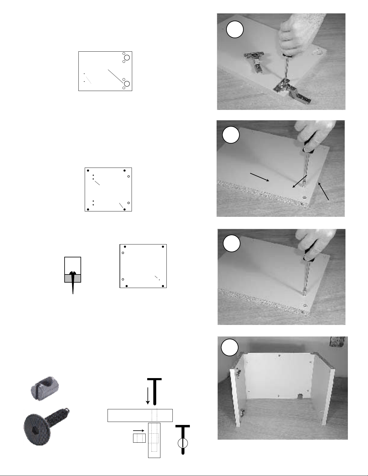
1. Attach the Euro hinges to the door as shown.
Press the hinge cups into their bores. Turn the integral hinge
cams to tighten.
(cabinet inside)
1
Door
cup holes for hinges
door handle holes
2. Attach the hinge mounting plates to the left side cabinet
panel.
Note the orientation in the photo. The hinge resembles the letter
"t". Locate the top of the "t" nearest the front edge of the side
panel as shown in the photo. Make sure the spring loaded
release lever faces the back edge of the cabinet.
Left Side (top)
(cabinet inside)
Front Edge
of Cabinet
holes for hinge
mounting plates
cross dowel holes
3. Attach the plastic door stop to the right side cabinet panel.
Use the small #7 x 3/4" silver colored wood screw.
Right Side (top)
Door stop detail
(cabinet inside)
2
Spring loaded
release lever
3
Top of "T"
mounting
plate.
Front edge
of cabinet
plastic door
stop hole
4. Attach left and right side panels to the back panel.
Do not install the panels upside down. Position the cord cut-out
to the bottom right. Use the 1/4-20 x 2" round head bolts and
cross dowels, and the supplied 4mm wrench to tighten the bolts.
The cross dowels may fit tightly into their holes. Tap them in with
a hammer if necessary. The drawing below shows how these
strong but simple fasteners fit together.
1/4-20"
cross dowel
Panel
Cross Dowel
1/4-20 x 2"
round head bolt
Bolt
Panel
4
Page 3
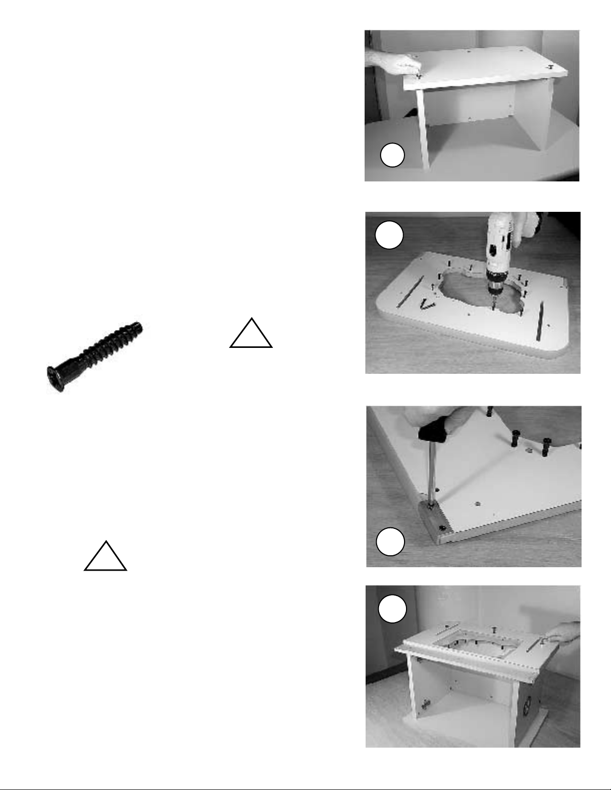
5. Attach the cabinet base panel.
Flip the cabinet over, as shown. Use the same 1/4" round head
bolts and cross dowels as above. When done, flip the unit right
side up. Note: the bottom side of the cabinet base panel has
counter bored holes to accept the bolt heads.
6. Install the (12) leveling screws (for the insert plate).
Place the routertop face down, as shown. Use a power drill, and
drive the screws in until they barely come through the other side.
You will fine adjust them in step 11. Some cracking of the
laminate's color layer may occur, but this will not affect the
product's performance.
5
6
!
7 x 40mm
leveling
screw
7. Attach the (2) aluminum trim strips to the routertop.
Use the (4) small #6 x 1/2 screws. Use a phillips screwdriver and
install by hand. Be careful not to over tighten the screws. Do not
use a power drill in this step! The trim strips are purely decorative.
Position the trim strip as shown, and drive the screws into the
bottom of the routertop.
Drive the screws into the
!
bottom of the routertop, not
into the side of the routertop!
Drive the leveling screws
into the (12) small holes. Be
careful not to drive a leveling
screw into the two larger
insert holes!
7
8
8 Attach the routertop to the cabinet.
Use (3) of the same 1/4" round head bolts and cross dowels
as used earlier. Attach the routertop to the cabinet sides and
back panel.
Page 4
 Loading...