

Page 1
S.p.A .
USE AND MAINTE NANCE HANDBOOK
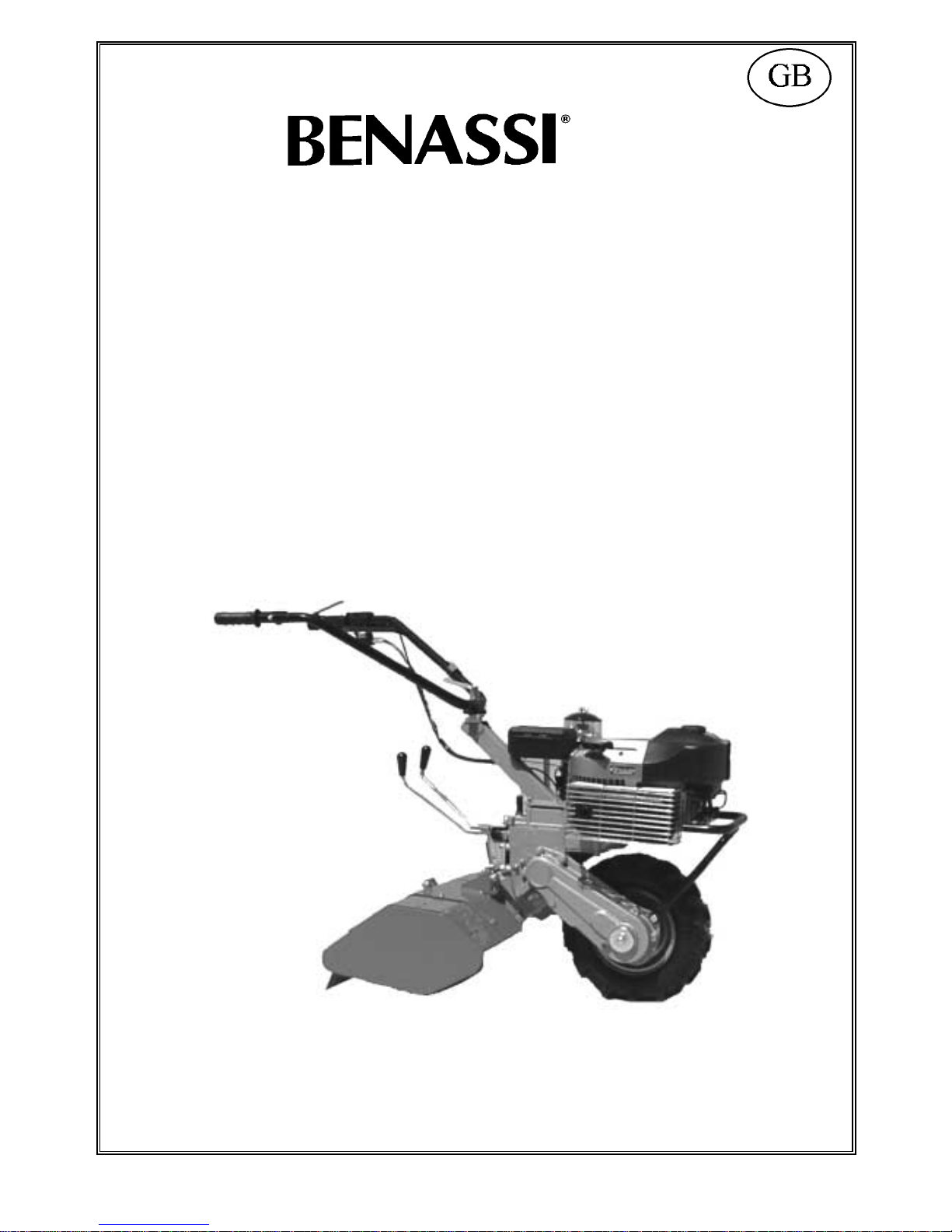
MOTORISED HOE
RT 80
06/07/01
Page 2
S.p.A.
RT 80
2
CONTENTS
1) Introduction
2) After- sales service and Wa rranty
3) Technical detail s
4) Packing and transport
5) Accessories
6) Safety ru les and limits on use
7) Starting and stopping
8) Operating a nd regulating the machine
9) Mill assembling
10) Maintenance and lubrication
11) End-of season servicing
12) Possible problems and solutions
13) Instructions for a good operation of the
machine
1 - INTRODUCTION
We are pleased that you chose a machine built by BENASSI SPA.
This booklet provides the information and data needed to preserve and use the machine properly.
Th e more you get t o k now y our farming machine, the bette r yo u will work. Therefore we s trongly suggest that before sta rting work, you carefully read and
understand this "USER AND MAINTENANCE" booklet.
You will find important informat ion o n using the m achine which will allow you to get the most of it s techn ic al capacities. You will also find preciou s
information on how to care for it and service it, in terms of safety, and a guide on running and servicing it in the best possible way during the lifetime of your
machine.
For reasons of technical progress, BEN ASSI SPA reserves the right to modify the mechani cal part s, the fi ni s hes and the ac c ess or i es. T he data
regarding measures, weights and performance are specified within DIN tolerance. The figures, the descriptions and the technical data are not binding.
2 - AFT ER-SALES SERVICE AND WARRANTY
BENASSI SPA pr ovides i ts c ustomers with an after- s ales ser vice for sol ving any pr oblem involving the use and the maintenance of its machinery. All the
machines are guaranteed for defective material for 12 months (one year) from purchase. For any need, refer to your dealer.
N.B. IMPORTANT WARNING FOR YOUR SAFETY
Al ways us e or i g i nal BEN ASSI SPA products, spare parts and accessories; any modification or application using non-original parts exem pts BENASSI
SPA from any responsibility
BEN ASSI SPA disc l ai ms al l r espons i bility in case of application of accessories made by other firms to its machines: Any warranty will be give n for said
applications even w hen such modifications have been tested by boards of control or certified by public bodies as tests on single machines are not valid.
BENASSI SPA WISHES YOU A PLEASANT W ORK W ITH OUR MACHINES
N.B. PAY SPECIAL ATTENTION TO THE INSTRUCTIONS MARKED OUT BY THE
FOLLOWING SIGN
THIS SYMBOL INDICATES DANGER: FAILURE TO COMPLY WITH THESE
INSTRUCTIONS MAY CAUSE INSIDIOUS OR EVEN FATAL IN JUR Y.
3 – TECHNICAL DETAILS
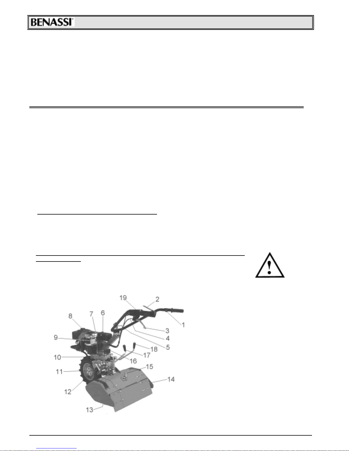
LIST OF MACHINE PARTS
1. Accelerator
2. Stop engine
3. Clutch lever
4. Clutch adjuster
5. Handle-bar adjuster
6. Tool-case
7. Start engine
8. Fuel inserting
9. Air filter
10. Oil level
11. Power take-off
12. Driving wheel
13. Mill
14. Mills bonnet
15. Bonnet adjustment
16. Oil inlet
17. Mills lever
18. Gearbox lever
19. Blocking pus h but t on
Page 3
SpA RT 80
3
ENGINE MINSEL COMPACT 7 HP
CYCLE 8
STROKE 2
FUEL TYPE Gasoline-oil mixture 4%
DISPLACEMENT 148 cc.
NET WEIG HT Kg. 100 complete with accessories
RPM 4500
MAX. POW ER OF THE DRIVING SHAFT 6 HP (Kw. 4,4) whit a consumption of 2,0 Kg/H
CLUTCH Oil bath cone clutch
GEARBOX Oil bath gearbox , four forward speeds and 1 reverse speed.
HANDLE-BAR Height and side adjustment
W HEELS 3.50.8 rubber or metal wheels
MOVING SPEED with:
•tyres 3.50.8
•the engine at 5.000 RPM
GEAR FORW ARD SPEED : Km/h REVERSE SPEED : Km/h
1° 1.5 2.6
2° 3.2
3° 4.5
4° 9.4
The engine f it t ed on t his c ult iv at or has f ollowing feat ures :
• Exhaus t guard
• Recoil starter
• Oil bath air filt er
• Safet y dev ic e for bot h forward and backward gear st opping t he t iller.
• Standard handlebar with vert ic al and s ide adjus t m ent .
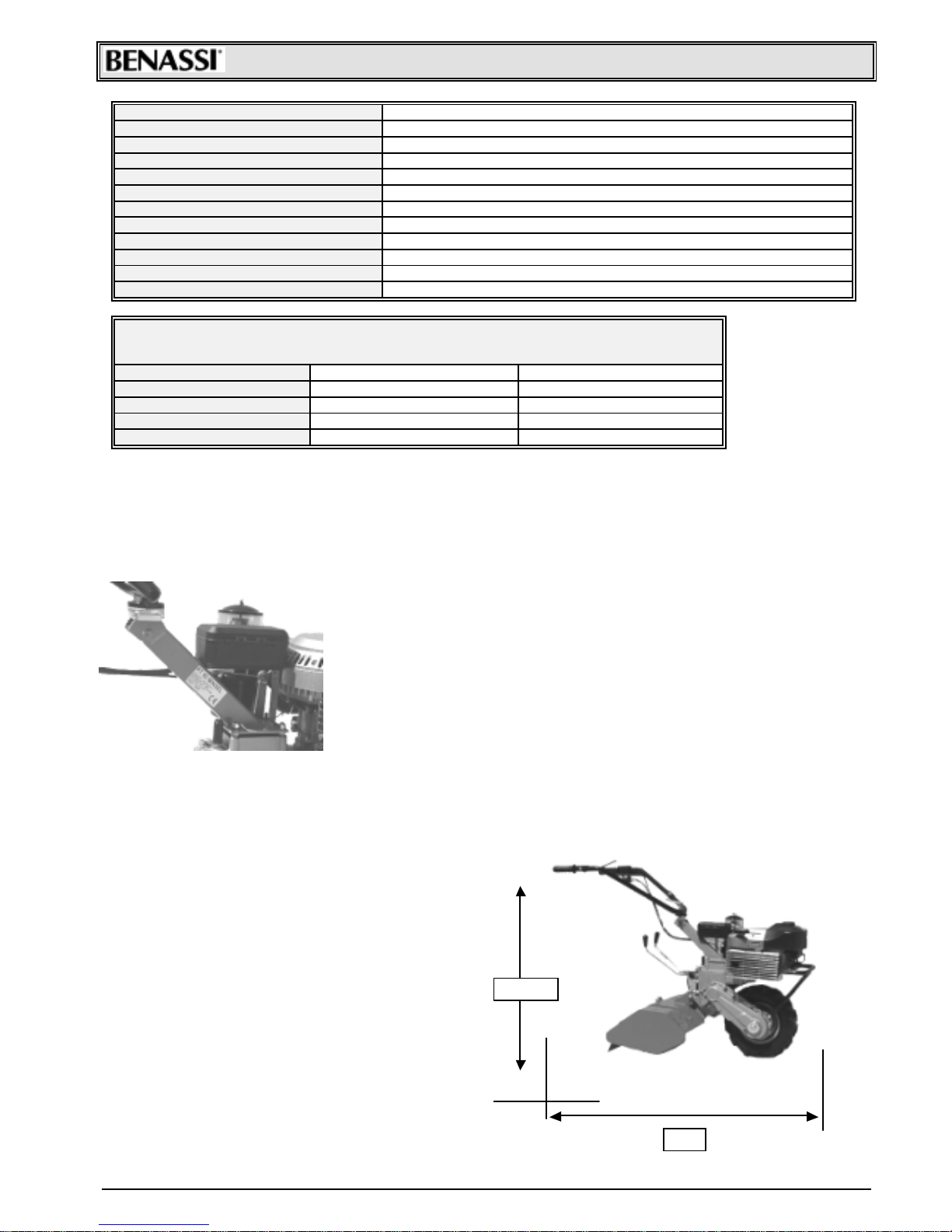
MACHINE IDENTIFICATION
The machine can be identified through its gearbox unit model and serial
number. The motor serial number is printed on the motor plate or on the motor
carburet or m anif old by t he m anufact urer.
The m ac hine identific at ion dat a are reproduc ed on a plat e loc at ed on t he handlebar support (right-hand side looking from the operating position), and the serial
number is reproduced both on the motor flange and on the unit (see picture
sideways)
Copy t he plate data and t he complet e serial number on t his manual in order to
have them at hand when neces s ary .
4 - PACKING AND T RANSPORT
The machine is generally s upplied without it s ac c es s ories , in c art on box es hav ing t he following overall dim ens ions :
• WIDTH : cm. 95
• HEIGHT: cm. 42
• LENGTH : cm. 85
• NET WEI GH T : Kg. 75 (without rot ary t iller)
During start-up the total exclusion of kinematic motions
through bloc k ing pus h but t on on c lut c h is s c heduled
Accessories are generally supplied separately from the
mac hine, with or without pac k ing
Free the mac hine f rom it s pack ing in order to prepare it t o
operate in t he f ollowing way :
a) Open t he packing and f ree t he machine f rom it, with the
help of another person lift the machine: one taking it from
the wheels, t he ot her f rom t he handle-bars ;
b) Adjust handle-bars as des ired;
c) Apply the ac c es s ories
1410
98+-15
Page 4
SpA RT 80
4
5 -ACCESSO RIES
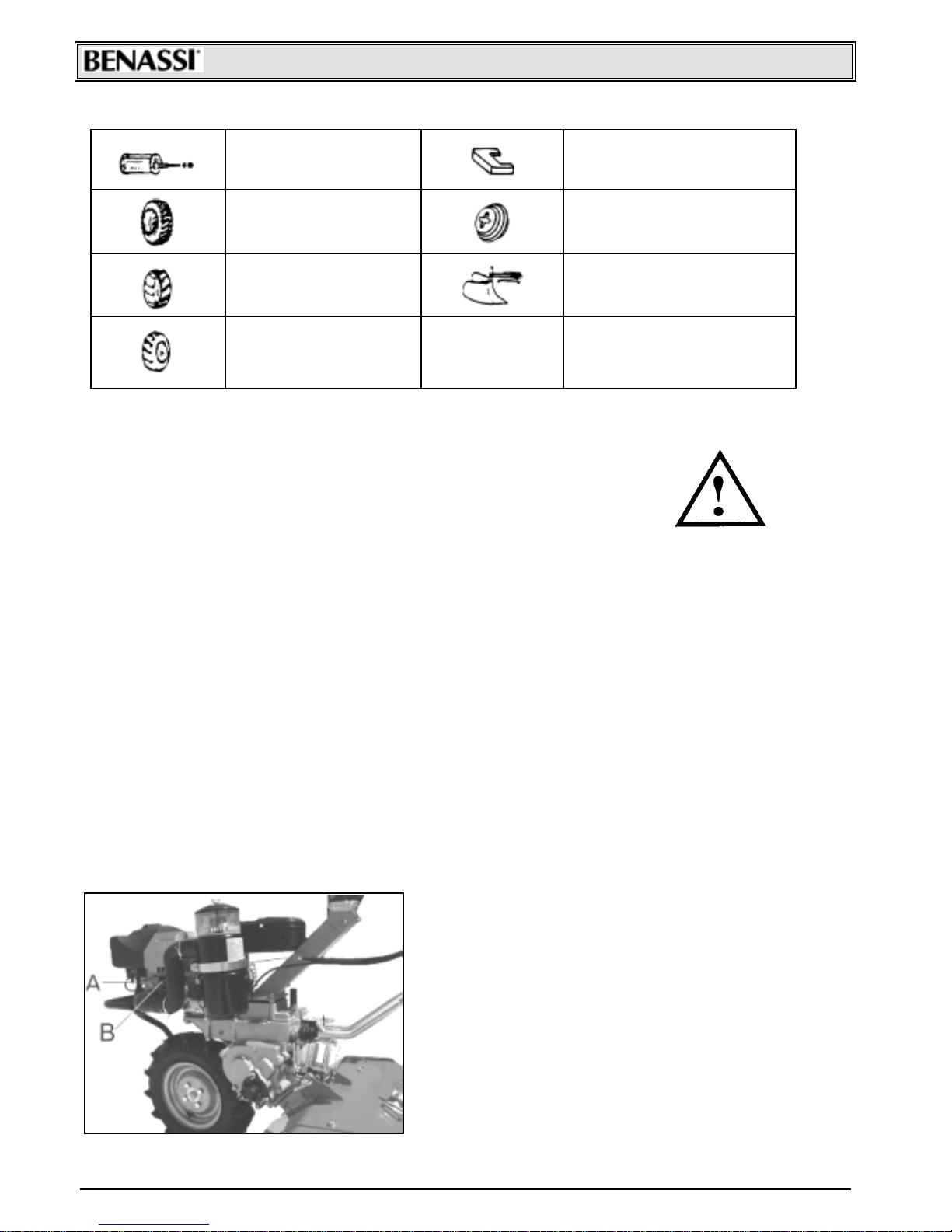
Spacer with pin for 2^ wheel
application
Cod. 94904400
Front ballas t Kg. 21, 5
Cod. 98000402
Second rubber wheel 3.50. 8
Cod. 97004400
Wheel ballas t Kg. 9, 5
Cod. 98060100
1^ iron wheel
Cod. 97004300
Adjustable furrow-opener with
connection
Cod. 91002511
2^ iron wheel
Cod. 97004500
(it is necessary to apply a
spac er c od. 94904400)
6 - SAFETY RULES AND LIMITS ON USE
IMPORTANT:
Before using the machine read carefully this operation and
m aint e nance manu al; It w ill allo w yo u to ge t fr om yo ur m ach ine th e
best performance of use and duration.
• The use of the m ac hine is f orbidden t o pers ons younger than 16 y ears .
• The operator is res pons ible of any pos s ible dam age and he s hould always driv e t he m ac hine c aref ully and saf ely .
• Before carrying t he m ac hine always em pt y t he fuel t ank .
• Before leaving t he m ac hine be s ure t hat it is f ully s t opped.
• Nev er use t he machine without heav y shoes and long t ransf ers. Alway s ins pect t he area where y ou want to work
tak ing of f s t ones , branc hes , c ables and any other t hing whic h c an be dangerous .
• Before st art ing working, m ak e s ure t hat a radius of m inim um 5 m . is c om plet ely free.
• Clean any pos s ible leak age of fuel.
• Fill up when t he engine is of f and not hot, always in an open spac e f ar from f ires or any heat ing s ourc e and ref rain
from s m ok ing during t his operat ion.
• Before s t art ing t he m ac hine m ak e s ure t hat y ou c an quic k ly s t op t he engine and t hat y ou are familiar with t he c ontrol
levers.
• Nev er allow the engine t o run in enc los ed s pac es where the highly t ox ic c arbon m onox ide c ould not evac uat e.
• Nev er st art or us e the mac hine not com pletely ass embled espec ially concerning t he saf ety dev ic es and the t iller
protec t ion guards which s hould always be c om plet ely as s em bled with all it s ex t ens ions .
• Nev er fix or c lean t he t iller blades or any other t ools when the engine is running.
• Nev er work in over 50% s loping ground.
• We are not res pons ible f or ac c ident s due t o t he wrong use of t he m ac hine neglec t ing t he above bas ic ins t ruc t ions .
• The elimination of t he lubric ant s us ed m us t be c arried out ac c ording t o t he norm s ex is t ing in t he c ount ry of us e.
7 – STARTING AND STOPPING
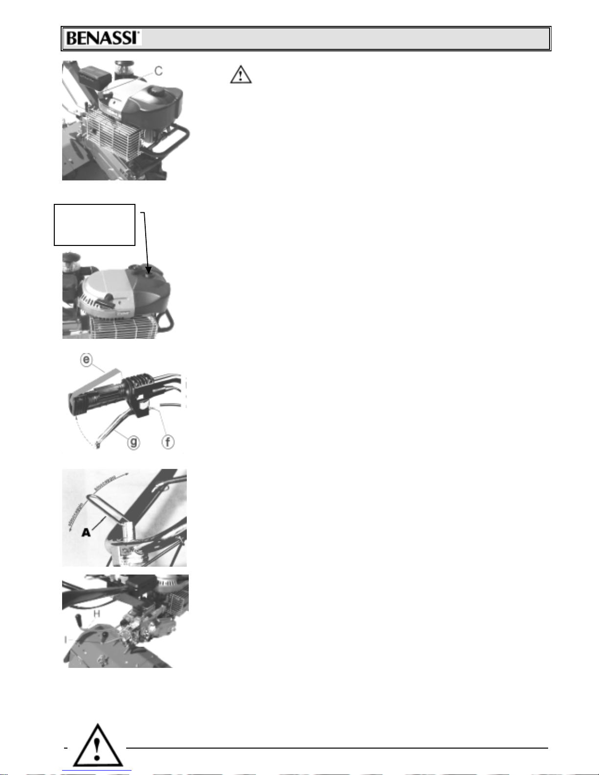
Whenev er you s et about s t art ing a c old engine, m ak e s ure :
• That the gasoline c ock “A” is alway s open. The lev er m ust be
placed t owards t he out let pipe.
• That t he gas oline has reac hed t he c arburet or. I f s o, by pum ping
piston “B”, the gasoline will drop down from the hole on the
upper sec t ion of c arburet or.
• Then, t urn t he ac c elerat or c ont rol lev er plac ed on t he handle-bar
of about ¼ .
• Chec k t hat t he gear-lev er and t he m ill-c ont rol lev er are idle.
Page 5
SpA RT 80
5
Check that stop lev er and clutch lever are blocked through the
block ing pus h but t on (R ef . ”F ”)
• Seize the st art ing-handle “C ” by one only hand, pull it gent ly until t he rat c het
gear is engaged. Then giv e a pull. The cord m ust nev er be lef t f ree quite
suddenly with the engine running, but followed till when it’s completely
winded-up.
8 - OPERATING AND REGULATING THE MACHINE
The ref uelling m us t be always perf orm ed bef ore s t art ing t he work, with c old and
st opped engine, us ing a f unnel, and in t he open air.
If f uel c omes out f rom the t ank, m ov e the mac hine at onc e bef ore start ing the engine
and dry well the parts wet of gas oline.
We recom mend to use alway s a f unnel with a net -f ilter in order to k eep back t he
poss ible im purit ies .
FU EL -TYPE: gaso l i n e-o i l mi xtu r e 4%
SAFETY LEVER : The m ot or hoe is prov ided with a red s afet y st op lev er c onnec t ed
to t he c lut c h lev er (R ef. G)t hrough s ide bloc k ing pus h but t on (R ef. “F ”).
The main f unct ion of this lev er c onsist s in st opping the engine in the mom ent in which
the hands are rem ov ed from t he driving-beams .
It ’s rec om m ended not t o bind t he s t op-engine lev er “E” t o t he handle-bar hand-grip.
CL UTCH L EVER : To assure a regular c lut c h working it is a good rule t o c hec k f rom
time to time the play that the clutch-lev er must have: (as shown in the picture) the
lev er idle-strok e m ust be f rom 8 t o 10 m m. I n the opposit e, act on the adjust er (G)
increas ing or dec reas ing t he play ac c ording t o t he need.
DRIVING-BEAMS :
Adjust able in height and trans v ersally , with pos sibility of loc king in the wished
posit ion. This operation m ust be c arried out by means of the screw-handle (“A”) placed
on the lowest s ec t ion of driving-beam s .
SPEED AND MIL L C ON TROL L EVER S :
The shifting of speed-lever (Ref . “I”)must always happen under the following
conditions:
• Wit h engine idling
• Wit h t he hand-c lut c h-lev er (R ef . G) pulled t owards t he hand-grip.
Anyhow, never f orc e t he lev er in it s s hift ing.
ATTENTION: The mills rotation must never occur , when the mach ine i s in r everse speed , an
in n er l ever -system d i sen g ag es th e mill or the reverse-speed.
FUEL INLET
FOR
REPLENISHING
Page 6
SpA RT 80
6
If this should not occur, apply to a skilled workshop by our concession ar y ag en ts.
In th e p i ctu r e, tu r n i n g l ever “ A” l eft th e r o tar y tiller is activated, on the contrary turning it right it is stopped.
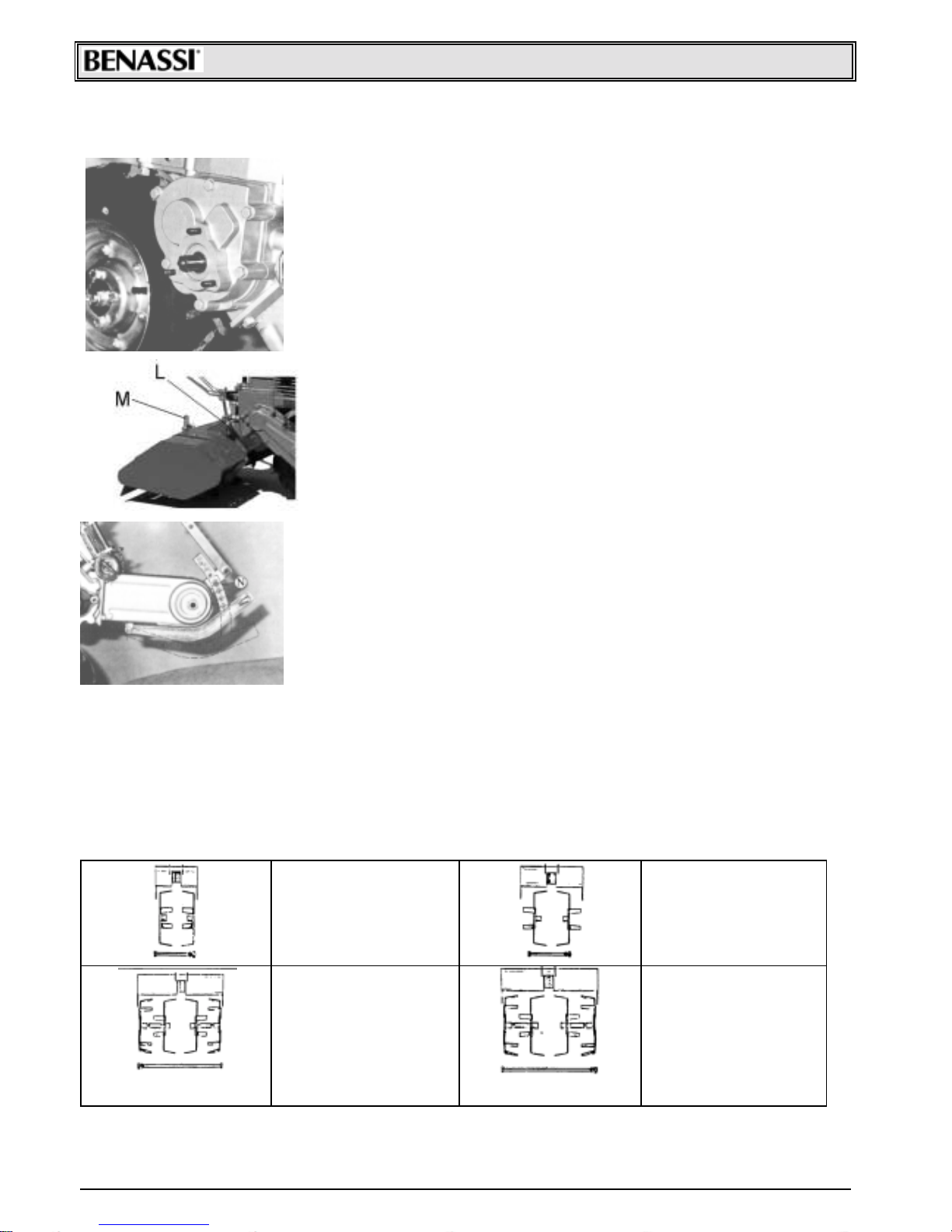
POWER TAKE-OFF :
The motor hoe is equipped with a lateral power take off, which may be
employ ed bot h with s t opped and running m ac hine.
The power take off and its own couplings are unif ied with most of commercial
f ittings.
POWER TAKE-OFF OUTLINE:
Splined 16 UN I 221X120 mm. W ork ing
Turning direction: lef t .
Max. rev . 440 at 5, 000 engine/ R PM.
MILL BONNET :
The m illing-depth may be adjus ted as f ollows: f or working on t he surf ace,
it’s rec om m ended t o k eep t he s af et y -m ill-bonnet lowered.
For a deep working, t o s ink m ore in t he ground.
For thes e operat ions it’s suf ficient to act on t he pin f ix ing t he bonnet “L” and on
adjust ing pin “M”.
DIRECTION - JOINTER :
For get ting a more regular m achine adv ancem ent it is suf f icient to operate t he
adjust able direc t ion-joint er.
When working on soft ground, it is required to keep the spur up, to help the
mac hine adv anc em ent .
On solid ground it ’s right to keep t he jointer down, so t hat sink ing in the earth it
prevents a t oo quic k m ac hine adv anc em ent .
For t his adjus t m ent , ac t on t he pin “N ” f ix ing t he joint er.
The machine presented in this manual has been designed to be used only in
agriculture and es pec ially for ground milling.
Any diff erent us e is c ons idered c ont rary t o it s proper us e.
The builder does not ass um e res pons ibilit y for dam ages or injuries due t o im proper
use of t he m ac hine.
Acc ording to the norm s, ev en t he respect of the operation, maintenanc e, and repairing condit ions f ixed by t he Firm
BEN ASSI SPA is part of a c orrec t us e
The machine c an be operated, m aintained and repaired only by thos e operators who hav e read this manual and are
informed of pos s ible dangers .
Any arbitrary m odificat ion on t he m ac hine ex em pt s t he F i rm B EN ASSI SPA f rom any res pons ibilit y in c as e of
damages.
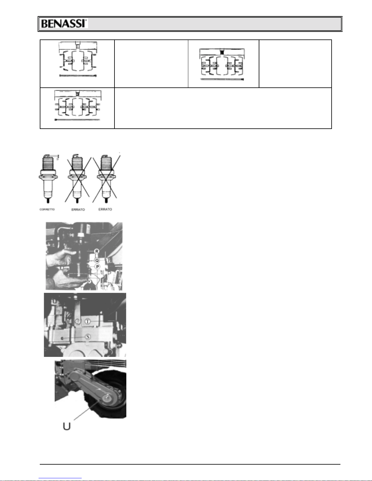
9 – MILL ASSEMBLING
WORKING WIDTH : 1 8 c m .
2 one-side joiners
1 pin cm . 17
1 bonnet c m . 18
WORKING WIDTH : 2 6 c m .
2 two-side joiners
1 pin cm . 17
1 bonnet c m . 26
WORKING WIDTH : 3 2 c m .
2 two-side joiners
2 one-side joiners
2 spac ers
1 pin cm . 31
1 bonnet c m . 33
WORKING WIDTH : 3 8 c m .
2 two-side joiners
2 one-side joiners
2 spac ers
1 pin cm . 36
1 bonnet c m . 38
Page 7
SpA RT 80
7
WORKING WIDTH : 4 5 c m .
4 two-side joiners
2 spac ers
1 pin cm . 36
1 bonnet c m . 45
WORKING WIDTH : 5 8 c m .
4 two-side joiners
2 one-side joiners
4 spac ers
1 pin cm . 55
1 bonnet c m . 58
WORKING WIDTH : 65 cm.
6 two-side joiners
4 spac ers
1 pin cm . 55
1 bonnet c m . 65
10 - MAINTENANCE AND LUBRICATION
PLU G-C ON TROL :
From time to time it’s necessary to check the plug wear-level and the
elect rodes -dis t anc e, which m us t be of 0. 5 m m , as s hown in the near drawing.
AIR FILTER CLEANING :
This operation m us t be perf orm ed regularly in t he following way:
• clean the f ilter ex ternally , s o to av oid that some eart h f alls inside during t he
disassembling.
• Loose the clips “P”, rem ov e the oil-cup “Q”, take away the f ilt er-element “R ”
and wash caref ully t he different part s with gas oline oil.
• Fill t he c up with new oil till reac hing t he lev el, as point ed out in t he pic t ure.
OIL INLET BLEED :
Every component of the gear-box and transmission is in oil-bath. It’s
neces sary to c heck f rom time t o time t he oil-lev el through sc rew “S” and f ill it up
again, if required, t hrough t he vent plug “T”.
USE ON LY OIL F OR TRAN SMISSI ON SAE 30
FR ON T-WH EEL OI L L EVEL PL U G :
Chec k from tim e t o t im e t he oil lev el on t he front wheel through plug “U ”, plac ed
on one side, as shown in the picture. For a perfect machine efficiency, a good
maint enanc e and a perf ec t lubric at ion are nec es s ary .
Chec k that air f ilter is c lean, in cas e of oil bath f ilter c heck lev el ev ery 8-10
operating hours or even m ore frequently when working in dust y grounds . U s e m ot or
oil to res t ore oil lev el and c lean t he c up before filling it.
GEARBOX Check oil lev el ev ery 50 operating hours remov ing the c ap on the
gearbox s um p k eeping t he m ac hine in horizontal pos it ion.
If necessary add SAE 30 oil. It is adv isable t o replace oil at leas t ev ery 100
hours.
MILLS Before s t art ing to work chec k that all s c rews are t ight , c hec k es pec ially
rotary t iller hoe fas t ening s c rews.
Page 8
SpA RT 80
8
11 - END- OF- SEASON MAINTENANC E
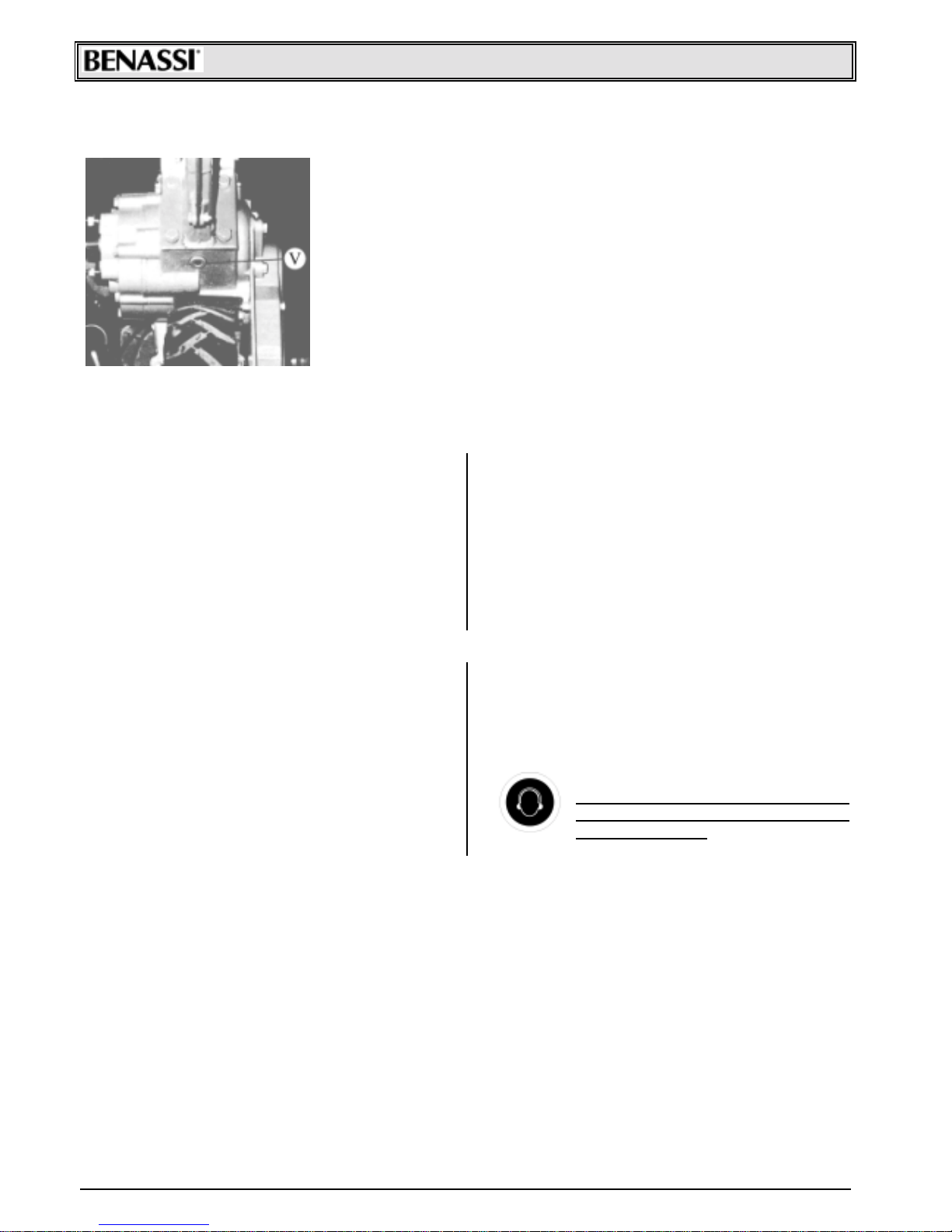
OIL DRAG PLUG :
For whatever mechanical repair in the ear-box or in the mill-descent, it’s
neces s ary t o rem ove t he oil.
To make the transmission empty , unscrew the plug “V” placed in the lowest
sec t ion of t he gear-box .
Befo r e p ar ki n g th e mach i n e:
• wash it accurately with gas oil,
• empt y t he c arburet or t ank and c lean or replac e air f ilt er,
• lubricat e and greas e all art ic ulat ed joint s and gears ,
• replace or repair pos s ible worn parts ,
• lubricat e c y linder with mot or oil t hrough the spark plug hole, pull the s tart-up
cord so that the piston makes some strokes
• Park t he m ac hine in a dry plac e with wheels on wood tables or ev en bet t er with wheels up from t he floor.
12 - POSSIBLE PRO BLEMS AND SOLUTIONS
Poss ible problem s t hat c an be s olv ed by t he m ac hine operat or:
MOTOR - The mot or does not s t art ; c hec k t hat :
• the gas oline in t he t ank is m ore t hen half .
• the gas oline c oc k is open
• if t he m ot or is c old , t he s t art er lev er is pulled
• the gas oline reac hes t he c arburet or
• the bleed on t he t ank c ap is not c logged
• carburetor jets are not clogged, if necessary , clean
them with air jet
• the s park plug spark s, in order t o carry out t his c heck
operation uns crew the spark plug; connec t it t o the power
supply cable, place the spark plug earthed metal part
(mot or cy linder) and mak e the mot or pulley turn as in the
start-up phase. If electrodes do not spark, check the
supply cable junctions, and if this does not solv e your
problems, replace the spark plug with one of the same
ty pe. If even this time y ou should not obtain positiv e
results, the defect concerns the electric plant (points,
condens er, coil et c.)I n this c ase it is adv isable to c ontact
the nearest s erv ic e (ac c ording t o t he mot or as s em bled on
the m ac hine).
13 - INSTRUCTIONS FOR A GOOD OPERATION OF THE MACHINE
• Carry out a good break ing-in of the mot or and of the
mac hine (f or at leas t 10 hours do not ex c eed 70%of m ot or
power)
• alway s us e t he c lut c h bef ore us ing any lever
• do not k eep the clut ch disengaged f or long periods of
time
• nev er f orce gear lev ers, if y ou c annot engage them ,
jerkily releas e t he c lut c h
• never f orc e t he m ot or.
• do not work at f ull speed f or long periods, in part icular
during hot day s
• periodically c hec k t yres pres s ure ( At m . 1. 3)
• when assembling the dif ferent tools, do not damage
shaf t s pigot and s pline, c hec k t hat t ool s c rews and loc k pin
are tight , in partic ular the rotary t iller hoe screws and the
sc rews f as t ening t he m owing bar
• do not leav e t he m ac hine in t he rain.
IMPORTANT: using the machine for a
long time you should use ear
protection system.
Page 9
SpA RT 80
9
TE S TS FOR CE CERT IFI CATIO N
EC C ert if ic at e of c onformit y c onf orm ing t o EEC direc t ions 89/ 392
40010 SanMatt eo della D ec im a BO I t aly Via Lam pedus a n° 1 Tel. (051) 682. 46. 56
Dec lare in s ole res pons ibilit y , t hat t he produc t C U LTIVATOR R T 80 to which this cert if ic at e applies , c onform s
to t he bas ic s af et y and healt h requirem ent s t o EEC direc t ions 89/ 392 and t o t he ot her relevant EEC direc t ions : PR EN
709/94 - N 67 C EN TC 144/ W G4 - PR EN 836/ 92 - EN 294.
THE PRESI D EN T
S.Matt eo della D ec im a li 20 -12 - 1994
TEST AND R ESU L T
TYPE: CULTIVATOR MODEL RT 80
Nois e lev el at operat or’s ear : LAeq = 87,1 dB (A)
Test c ondit ion: 1, 6 Mt at t he c ent er of t he handlebar
Handlebar v ibrat ion ac c ording t o I SO. 5349 : 5, 7 m / s ec2
Page 10
SpA RT 80
10
S.p.A.
Via Lampedusa, 1 - 40010 S . M AT TEO DELLA DECIM A (B O) - I TA LY
TE L. 0039/051/ 82.05.34 T E LE FA X 0039/ 051/682.61.64
 Loading...