

Page 1
MB_EN_ACXplus-R_BEL_02
Beluk GmbH
Tel.: +49 8861 2332 0
Taubenstrasse 1
Fax: +49 8861 2332 22
86956 Schongau
Germany
http://www.beluk.de
x
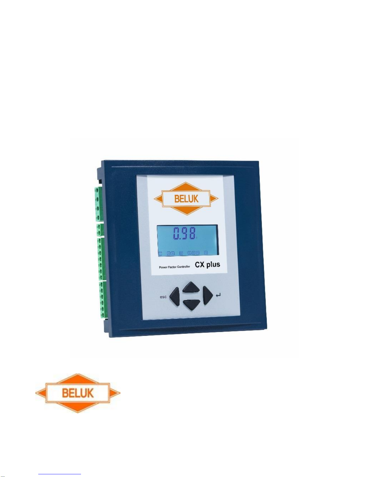
CX plus Operating Manual
s
Page 2

General safety notes
Failure to observe the following instructions can lead to serious
injury or death !
During installation, there is a risk of electric shock. For this reason,
electrical devices may only be installed, operated, serviced and maintained
by qualified personnel. A qualified person is one who has the ability,
experience and knowledge necessary for the construction, installation and
operation of electrical equipment and is trained in the detection and
prevention of potential hazards.
During installation and maintenance, the relevant regulations for
installation of switchgear and for preventing accidents must be observed
and complied with.
Devices with damaged or open housings or terminals may not be
connected to the mains and must be disconnected immediately.
After disconnection of the device, wait for 10 minutes until the capacitors
are discharged before removing doors or covers. After that, check to
ensure that the compensation system has been de- energised.
Beluk GmbH assumes no responsibility or liability for injury to persons or
damage to equipment due to improper installation or installation not for
the intended use carried out by qualified personnel.
Page 3
Page 4

New features of the CX plus over the BLR- CX
Modbus: no longer as an external add- on module,
now optionally installed internally.
Alarm memory: enables the storage of the last 10 alarms
New alarms: THD I alarm
I-Low alarm: can be disabled via digital input now:
SETUP/ 500/ 518 → “YES” = I-Low alarm blocked
Control algorithm: in addition to LIFO, AUTOMATIC (best fit) and
PROGRESSIVE, the FIFO algorithm has now also been implemented
Outputs: 6 or 12 stages, separate fan relay (can be used as 7
th
/13th
stage)
Display: to extend the service life of the backlight, it is turned off
60 seconds after last usage.
Storage U
max
and THD U
max
Digital input:
Choice between target cosϕ1 and target cosϕ2, signalisation of an
external alarm or to disable the I-Low alarm
Temperature sensor: NTC now internal.
Page 5

Installation and commissioning:
1) Before installation, the connection data of the CX plus must be
compared with the data of the supply network and the installation.
2) The working area must be disconnected from voltage and secured
against unauthorised and unintentional restart. The absence of
voltage must be verified with a standardised instrument/ testing
device. The voltage- free system must be grounded and shortcircuited. Adjacent live parts must be covered or placed behind
barriers.
3) The current transformer must be short-circuited! A current
transformer that has NOT been short-circuited generates very high
voltages posing a danger to persons and equipment. The current
transformer can thereby be destroyed.
4) Disconnect and remove the old reactive power controller.
5) Plug the CX plus into the switch panel section and fix it with the two
mounting brackets. (Section 138 x 138 mm)
6) Connect the protective conductor to the PE terminal of the metal
back of the CX plus.
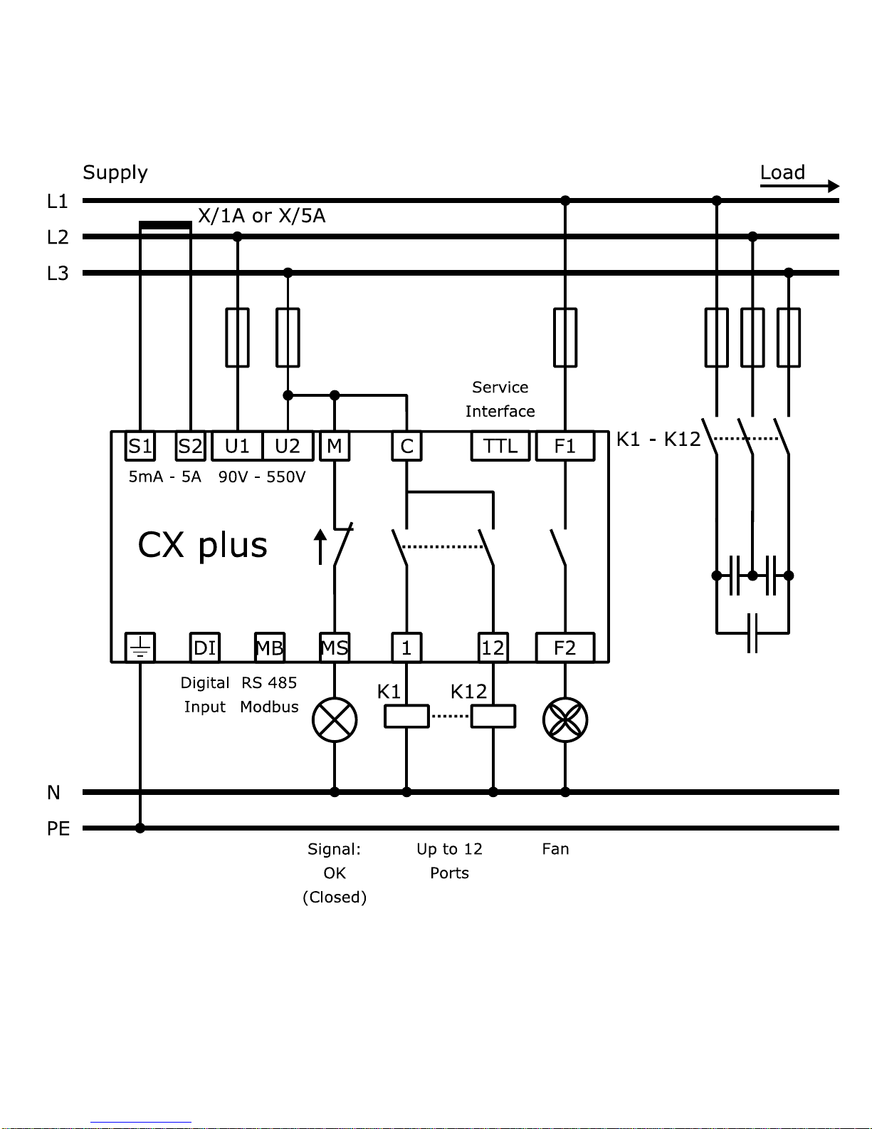
7) Connect the connecting lines as shown in the wiring diagram.
(Current transformer: K [power plant] to S1, L [load] to S2)
Page 6

8) Remove current transformer jumper.
9) Switch on voltage.
10) With a proper connection and correct connection data, the LCD lights
and the LCD test is active for 1 second.
11) Activation of user-guided initial commissioning “FIrSt SEtUP“ after
confirming “YES“. Afterwards all required parameters are requested
by CX plus. The choice of “NO” requires, that the user implements the
following parameters (12) … 15)) manually.
12) The current transformer factor (Ct) must be entered.
13) The nominal voltage (Un) and the voltage transformer factor (Pt)
must be entered, too.
14) Start the “Automatic initialisation” (AI) or enter the Phaseoffset
(PO) manually.
15) If the „Automatic initialisation” was successfully finished, the
message “AUTO” appears on the LCD.
Control starts after the discharge time lock.
Page 7

Questions during commissioning:
1) No AUTO display → control stopped
Reasons: Manual operation, control is switched off, temperature is
too high, current is less than 15 mA, voltage or THD of voltage are not
permitted
2) U ALARM display → voltage out of tolerance
Check settings for rated voltage (SETUP/ Un) and
voltage transformer (SETUP/ Pt)
3) I Lo ALARM display → no current flow
Possible causes: Connection from the current transformer to
the controller is not correct; current transformer
jumper is not removed; transformation ratio is too large; no current
4) EXPORT display → feeding back of active power
If there is no real feeding back, connect voltage and
check current (phase polarity)
→ section Incorrect connections/ AI – automatic initialisation
5) Incorrect Cos phi → incorrect connection
Connect voltage and check current (phase, polarity)
→ section Incorrect connections/ AI – automatic initialisation
6) Outputs are switched off again immediately
→ section Incorrect connections/ AI – automatic initialisation
7) Frequent switching of the outputs
→ output of the capacitors first needs to be detected
Page 8
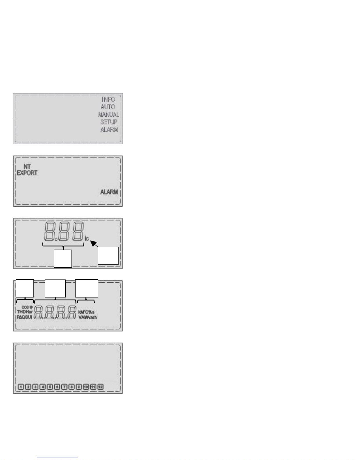
Display:
INFO: Stage database
AUTO: Automatic operation
MANUAL: Manual operation
SETUP: Settings menu
ALARM: Alarm memory
EXPORT: Feeding back of active power
NT: 2nd target cosϕ is active
ALARM: Flashes if there is an
alarm notification
1st line:
I) cos ϕ/ menu items
II) inductive/ capacitive
2nd line:
I) code of metered and set values
II) metered and set values/ alarm
codes
III) units
Stage display:
Status of the stage (on/ off)
Stage faulty (flashing)
I
II
III
II
I
Page 9
Operation:
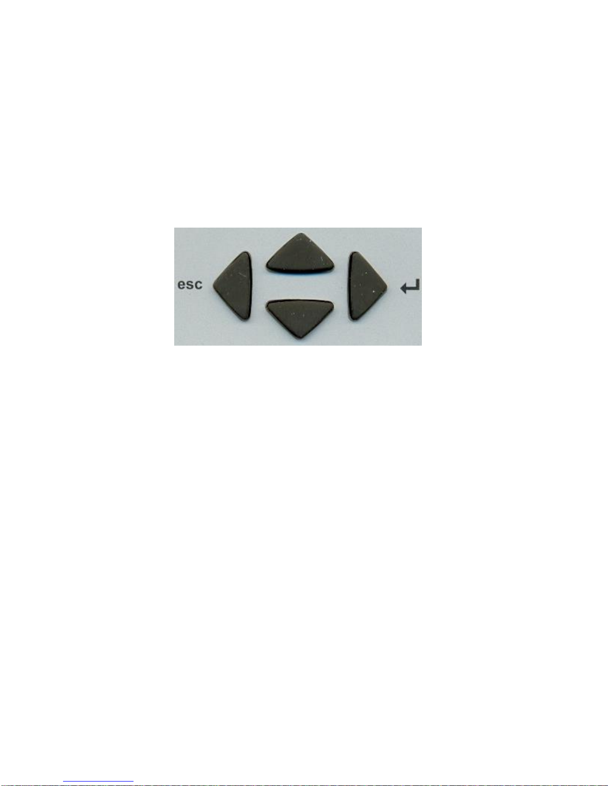
The controller is operated using 4 keys.
Increase values
Select menu items
Exit menus/ Esc
Cursor to the left
Reset alarm (5 sec.)
Opens menus/ Enter
Cursor to the right
Settings
Decrease values
Select menu items
Input parameters:
↑, ↓
→
↑, ↓
→
←
Digit adjust (up/ down)
Move to next position
After the last digit is set, selection of:
- Multiplier k (kilo) or M (Mega)
- Preceding sign i (inductive) or c (capacitive) (flashing of i or c)
Application of values at the end
Abort entry
Page 10
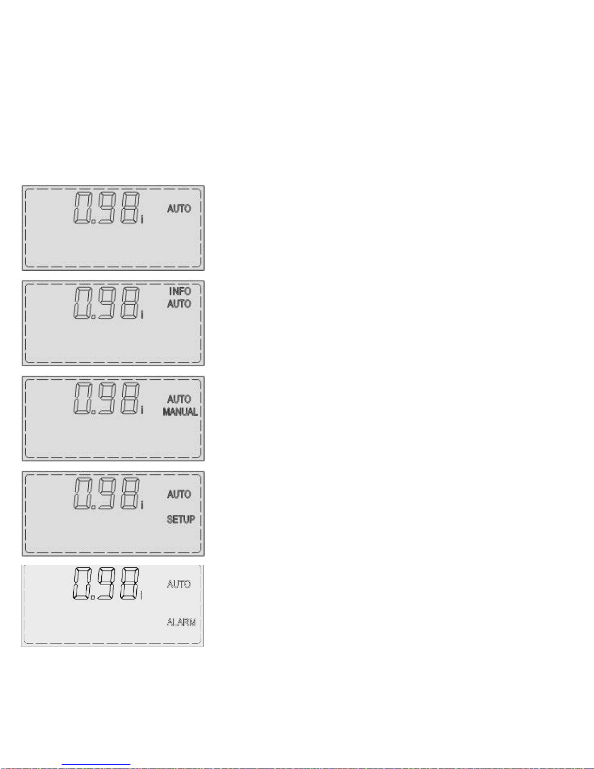
Main menu:
Select menu items with ↑, ↓, enter the submenu with →
Measurement value display:
(Change with ↑, ↓)
ULL, ULN, I, P, Q, ΔQ, S, THD U, 3.-19. Har. U,
THD I, 3.-19. Har. I, cosϕ, PF, APF, Hz(F), t(°C),
thi (°C), OPh (h), tanϕ, U hi, THD U hi
INFO stage database:
Power and power loss of stages, number of
switching operations, stage type, operating hours.
(→ section INFO stages database)
MANUAL operation:
Intentional switching on and off of
switching outputs.
(→ section MANUAL operation)
SETUP settings menu:
Rated voltage (Un), current transformer (Ct),
voltage transformer (Pt), automatic initialisation
(AI), control on/ off (PFC), target cosϕ 1 (CP1),
switching time (St), stage type (Out)
(→ section SETUP settings menu)
ALARM memory:
Memory buffer shows the last 10 alarms. The most
recent alarm is in the first position.
Page 11
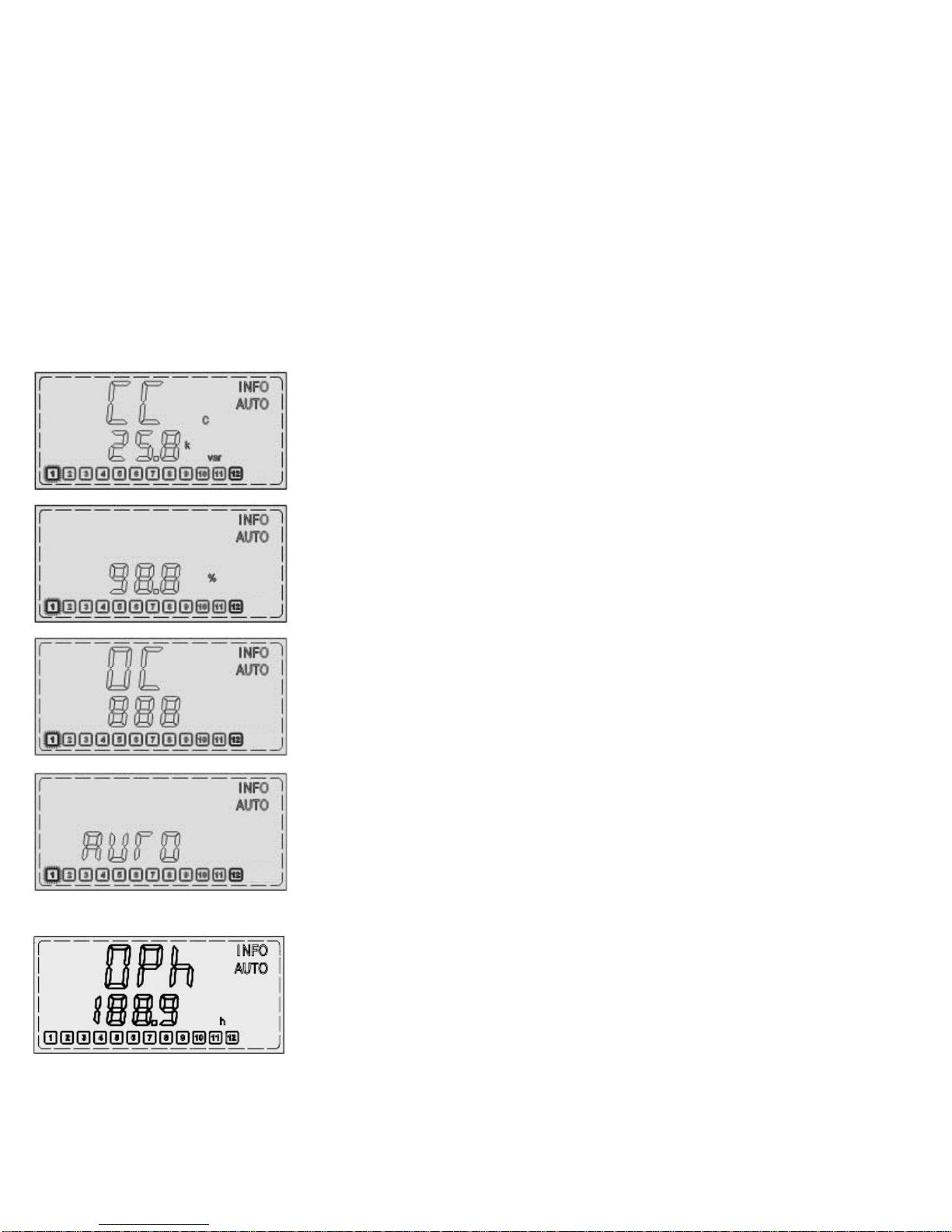
INFO stage database:
Please note: The current status of the outputs is not displayed.
Browse through stages with ↑, ↓ and select with →. The selected
stage flashes. ↑, ↓ displays the following information:
Current capacitor output
The output relates to Un
Output reduction of the capacitor:
Current output/ nominal output in %
Number of operation cycles
Stage type:
AUTO: Automatically controlled stage
Fon: Fixed stage on
Foff: Fixed stage off
FLty: Stage faulty and disabled
Operation hours:
Shows how many hours the corresponding stage has
already been in operation. Selected stage flashes.
Page 12
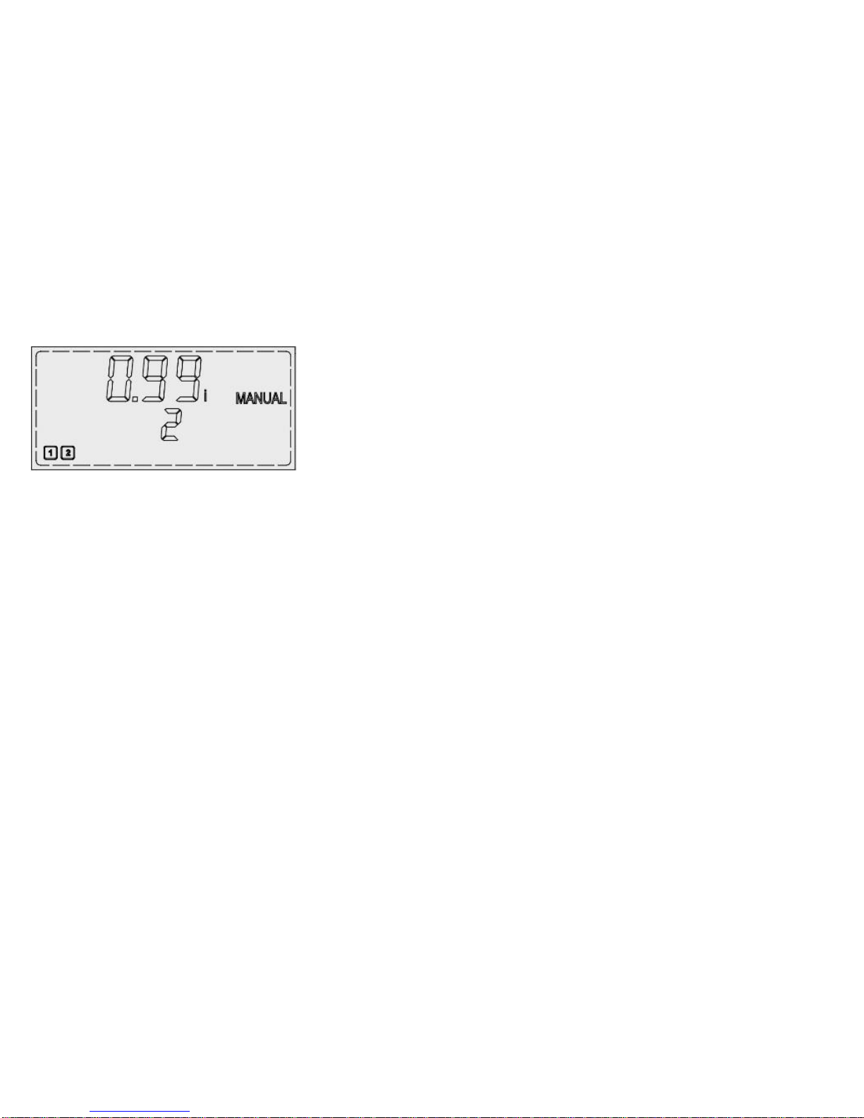
MANUAL operation:
Enter manual operation by pressing → for three seconds.
Browse stages with ↑, ↓. The selected stage is displayed in line 2 as a
number. → switches the stage on or off.
Exit manual operation with ←.
Important information:
- In the menu Manual operation, only stages with stage type AUTO can
be switched. In LIFO mode, FIFO mode and combined filter mode, the
menu Manual operation is disabled. (→ Reference Manual)
- The discharge time lock is also active in manual operation.
(Stages are disabled for a certain time after shutdown)
- The voltage must be within the tolerances, otherwise all stages will
shut down. The respective stages can not be switched in Manual
operation.
- THD U-, THD I- and overtemperature- Alarm block the switching of
stages in manual mode.
- After exiting manual mode, there is automatic control starting from
the set status.
Page 13

SETUP settings menu:
After opening SETUP, submenu 100 appears. → Open menu 100.
↑, ↓ Menu 200 - 600 & 800, with optional Modbus: 200 - 800
(locked with password → Reference Manual)
Un
Ct
Pt
AI
PFC
CP1
St
OUt
Rated voltage (correct setting is very important)
For voltage monitoring and stages database reference.
Current transformer ratio (must be set)
The value is used for calculation and activation of some
measurement values in the measurement menu.
Voltage transformer ratio
Important as the basis for setting Un
Automatic initialisation
→ section Incorrect connection/ AI – Automatic initialisation
CONTROL ON/ OFF/ HOLD
Switching on, switching off, freezing the control
Target cosϕ 1
Basis for compensation target
Switching time
Defines the speed of the controller
Stage type
Defining stage type: AUTO, Fon, Foff,
Reset faulty stages (FLty)
Page 14

Incorrect connection/ AI – automatic initialisation:
In case of incorrect connection of the voltage or current path (phase, polarity),
the reactive power controller cannot be operated. Thus, the connection should
be corrected. Since this is not always possible, the CX plus alternatively
provides the following functions:
Automatic initialisation: SETUP/ 100/ AI
The AI switches all outputs on and off several times. This takes a few minutes.
Unused outputs are set to “Foff”.
Stage values are not detected during this process.
After the end of the AI, the function of the controller should be checked.
Requirements for a successful operation of the AI:
- The voltage is within the tolerance
- The current transformer is connected (no simulation)
- Capacitor banks are installed, functional and secured
Possible issues for successful AI:
- Load fluctuations
- Small current signals
Error messages AI/ Abrt:
AI was aborted because no clear result was possible; the control is OFF.
The Phaseoffset can be entered manually as well:
Entering of the correct Phaseoffset SETUP/ 206 → Reference Manual
Page 15

Stage detection:
During each switching operation, the stage value is determined (except if
this feature is disabled SETUP/ 308 → Reference Manual).
The detected values are updated in the stages database. A loss of capacity
can be determined there.
If a stage does not work in the first three switching operations, it is
automatically assigned to the stage type Foff.
After commissioning, the existing stages have stage type Foff:
Is the current transformer jumper removed?
Is the position of the current transformer correct?
Are all currents and measuring/ operating voltages present?
Faulty stages:
A stage that switches three consecutive times without measurable
success is declared to be faulty. After 24 hours, another test is started.
Stage display: flashes
Status: Flty, stage is disabled
Procedure:
Do individual stage symbols flash during operation mode?
Check fuse, contactor and capacitor output of the corresponding stage.
Acknowledgement in SETUP/ 100/ OUt or restart (interruption of the
measuring/ supply voltage) of the CX plus.
Page 16

Alarms:
Alarm system settings: SETUP/ 500 → Reference Manual
U
ALARM:
Measuring voltage out of tolerance
I Lo
ALARM:
Measuring current < 5 mA (check I-measuring path)
SETUP/ 500/ 518 → “YES” = I-Low alarm blocked
I Hi
ALARM:
Measuring current > 6 A (transformation ratio of the
built-in current transformer is too small)
PFC
ALARM:
Compensation target unreachable (check system)
HArU
ALARM:
Limit for THD U has been exceeded
HArI
ALARM:
Limit for THD I has been exceeded
StEP/ FLtY
ALARM:
Faulty stages have been detected
SPL/ Nr
ALARM:
Power loss levels below 75 %
Stage number and error code will flash alternately
thi
ALARM:
Overtemperature shutdown of the stages
OPH
ALARM:
Max. operation hours device reached (maintenance)
OPC/ Nr
OPHS/ Nr
ALARM:
Max. operation cycles/ operation hours stages
reached (maintenance)
Stage number and error code will flash alternately
AI/ Abrt
ALARM:
Abort of the automatic initialisation
Re-start the AI when the grid is calmer
or manual setting of the phase offsets
(SETUP/ 206 → Reference Manual)
Page 17

Factory settings
SETUP/ 100
IMPORTANT SETTINGS
open
Un/ rated voltage
400 V
Ct/ current transformer
1
Pt/ voltage transformer
1
AI/ start Ai
NO
PFC/ control
ON
CP1/ target cosϕ 1
1
St/ switching time
10 s
Out/ stage type
AUTO
SETUP/ 200
MEASUREMENT
locked
201/ rated voltage
400 V
202/ current transformer
1
203/ voltage transformer
1
204/ tolerance voltage
10 %
205/ voltage LL
NO
206/ phase offset
0
207/ start Ai
NO
208/ synchronisation
AUTO
209/ temperature offset
0°C
SETUP/ 300
CONTROL SETTINGS
locked
301/ sensitivity
60 %
302/ target cosϕ1
1.00
303/ target cosϕ2
i 0.95
304/ EXPORT cosϕ2
NO
305/ switching time
10 s
306/ St stage exchange
2 s
307/ active stage exchange
YES
308/ active stage detection
YES
309/ lock faulty stages
YES
310/ control on/off/hold
ON
311/ control algorithm
1
312/ offset reactive power
0 var
313/ asymmetry factor
1
314/ Qcap stages Off
NO
315/ stage distribution
NO
316/ detect. def. stages
YES
SETUP/ 400
STAGE DATABASE
locked
401/ discharge time lock
75 s
402/ nominal stage value
c 3 var
403/ stage type
AUTO
404/ operation cycles
0
405/ stage operation h
0 h
406/ fan relay as stage 13
NO
Page 18

Factory settings
SETUP/ 500
ALARM SETTINGS
locked
501/ manual reset
NO
502/ THD U Limit
20 %
503/ THD stages off
NO
504/ delay of harm. alarm
60 s
505/ I= 0 freeze controller
NO
506/ maintenance alarm
NO
507/ operating cycles limit
500 k
508/ limit OPh
65.5 kh
509/ limit OPh stage
65.5 kh
510/ THD I limit
50 %
511/ DI= Hi active
YES
512/ Temp1 limit
30 °C
513/ Temp2 limit
55 °C
514/ control alarm
NO
515/ faulty stages alarm
NO
516/ power loss
NO
517/ alarm illumination
NO
518/ digital input function
CP 2
519/ info lock I-Low
NO
520/ DI-Alarm switch off
stages
NO
521/ I-Low-Alarm
YES
522/ delay I-High-Alarm
10 s
523/ switch off interval
60 s
SETUP/ 600
RESET
locked
601/ factory settings
602/ stages database
603/ operating hours
604/ average power
factor
605/ max. temperature
606/ alarm
607/ firmware info
608/ password change
242
SETUP/ 700
MODBUS SETTINGS
locked
701/ baud rate
19200
702/ parity
EVEN
703/ address
1
SETUP/ 800
Backlight Options
locked
801/ backlight
Commissioning-Mode
NO
802/ delay time
0,25 h
Page 19

Technical specifications:
Voltage:
90- 550 V, 1 ph., 50/60 Hz, 6 VA
Current:
5 mA- 6 A, 1 ph., <1 VA,
Switching outputs:
Relay, NO contact,
common contact supply: max. 10 A 250 V
AC/ 5 A, 400 V AC/ 1 A
Digital input:
90- 250 V AC
Temperature measurement:
NTC, internal
Signal contact:
Pot.- free relay, normally closed contact,
48 V DC/ 1 A, 250 V AC/ 5 A, 400 V AC/ 1 A
Optional NO/ NC
Fan control:
Pot.- free relay,
48 V DC/ 1 A, 250 V AC/ 5 A, 400 V AC/ 1 A
Interface:
Optional: RS485 Modbus
Ambient temperature:
Operation: -20 °C to 70 °C
Storage: -40 °C to 85 °C
Humidity:
0 %- 95 %, condensing not allowed
Overvoltage category:
300 V LN/ 519 V LL CAT III
or 550 V/ CAT II
Connection:
Screw terminals, pluggable
Housing:
Front: Instrument housing, plastic
Back: Metal
Protection type:
Front: IP41, Back: IP20
Page 20

Technical specifications:
Weight:
Approx. 0.6 kg
Dimensions:
Housing: 144 x 144 x 58 mm (WxHxD)
Cut-out: 138 (+0.5) x 138 (+0.5) mm
Alarm memory:
Storage of the last 10 alarms
Standards:
IEC 61010- 1
IEC 61000 6- 2
IEC 61000 6- 4: level B
IEC 61326- 1
UL 61010
Conformity:
CE, NRTL(UL), c NRTL (cUL), EAC
Algorithms:
AUTOMATIC (best fit)
LIFO
FIFO
PROGRESSIVE
Combined filter
Max. operating height:
≤ 2000 m
Max. contamination level:
2
 Loading...