


Conveyor Belt Scale
Belt-Way Scales Conveyor Belt Scale, Model 40, Model 50, Model 100, Model 200 Product Manual
...
Phone: (815) 625-5573 beltwayscales.com sales@beltwayscales.com
Belt-Way Scales, Inc.
Conveyor Belt Scale
Product Manual
Belt-Way Scales, Inc.
1 Beltway Rd.
Rock Falls, IL 61071 USA
Phone: (815) 625-5573
www.beltwayscales.com

Phone: (815) 625-5573 beltwayscales.com sales@beltwayscales.com
Page 2 of 44
Conveyor Belt Scale
Product Manual
This page intentionally left blank
Phone: (815) 625-5573 beltwayscales.com sales@beltwayscales.com
Page 3 of 44
Conveyor Belt Scale
Product Manual
Safety and Warnings
All Belt-Way components MUST be used as described in this manual!
Please note the labels on the integrator and in the manual denote
dangerous voltage. Failure to take safety precautions may result in
serious injury or death.
The protective conductor terminal (Earth Ground) is
signified by the following label.
It must be properly connected to earth ground per local electrical codes.

Phone: (815) 625-5573 beltwayscales.com sales@beltwayscales.com
Page 4 of 44
Conveyor Belt Scale
Product Manual
Table of Contents
Scale Accessories ................................................................... 6
Integrator Specifications ...................................................... 7-9
Mechanical Installation ...................................................... 10-16
Integrator Installation ........................................................ 17-22
Integrator Board .................................................................................................................................... 18
Sensor and Power Wiring ....................................................................................................................... 19
Sensor Board ......................................................................................................................................... 20
Terminal Board with AC Power Supply .................................................................................................... 21
Terminal Board with DC Power Supply.................................................................................................... 22
Integrator Configuration .................................................... 23-36
Setup Wizard .................................................................................................................................... 24-25
Scale Setup ............................................................................................................................................ 26
Scale Calibration .................................................................................................................................... 27
Zero Calibration ......................................................................................................................... 27
Test Weight Calibration ......................................................................................................... 28-29
Material Test Calibration ............................................................................................................ 30
Totals and Diagnostics ....................................................................................................................... 31-33
Scale Totals ................................................................................................................................ 31
Scale Diagnostics........................................................................................................................ 31
Device Setup ..................................................................................................................................... 34-35
Plant Connect ............................................................................................................................ 35
Administration ....................................................................................................................................... 36
Routine Maintenance ............................................................. 37
Troubleshooting ............................................................... 38-39
Product Warranty .............................................................. 40-41
Phone: (815) 625-5573 beltwayscales.com sales@beltwayscales.com
Page 5 of 44
Conveyor Belt Scale
Product Manual
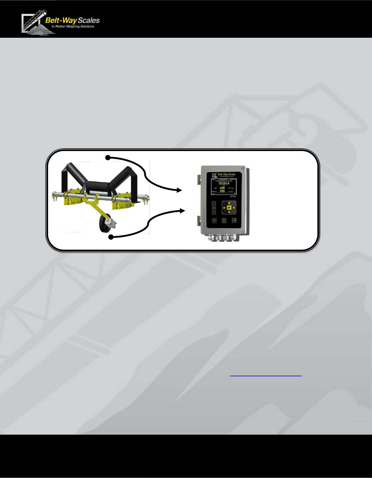
Introduction
The Belt-Way conveyor belt scale is a highly accurate and cost effective inmotion weighing system. It is designed to measure material flow over a
conveyor belt in real-time. The primary components are the integrator (AKA,
controller, display, indicator), load cell assemblies, and speed sensor. The
scale system processes speed and load signals to accumulate weight and
calculate flow rate.
This manual covers the following belt scale models:
• Model 45, Model 50 (Low capacity)
• Model 100, Model 150, Model 200 (Medium capacity)
• Model 350, Model 500, Model 1000 (High Capacity)
This manual pertains to scales operating on firmware 6.43 and above.
A manual for previous versions may be found at beltwayscales.com
BELT
LOAD
BELT
SPEED
ACCUMULATED
WEIGHT
+
FLOW RATE
Phone: (815) 625-5573 beltwayscales.com sales@beltwayscales.com
Page 6 of 44
Conveyor Belt Scale
Product Manual
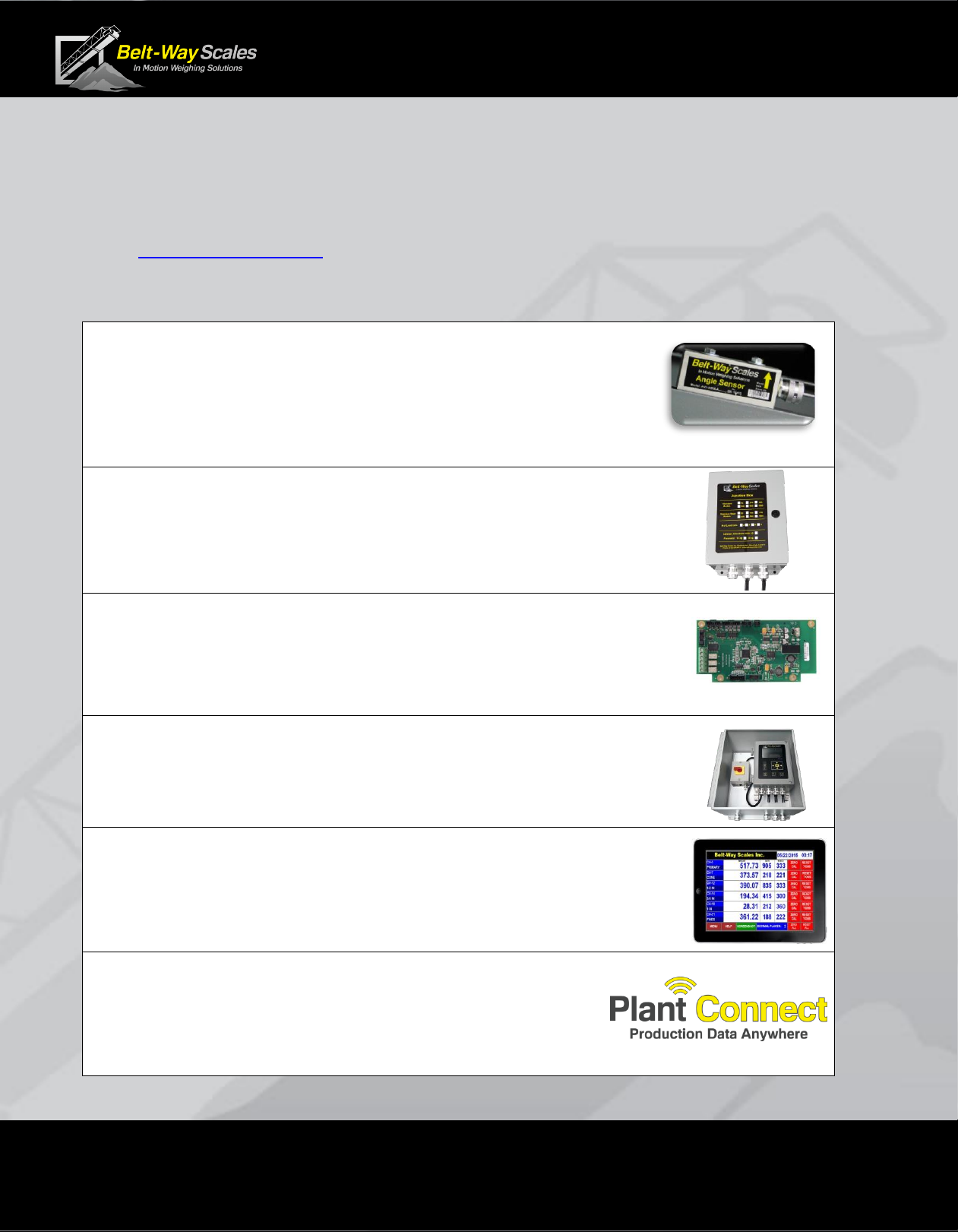
Scale Accessories
The Belt-Way conveyor belt scale works with a range of accessories
designed to maximize accuracy, efficiency, and safety.
Visit beltwayscales.com or call us today for a complete list of all the
accessories that Belt-Way has to offer.
• Angle Sensor
The angle sensor eliminates the need for constant recalibration
when the scale is installed on a variable angle conveyor or portable
machine.
• Junction Box
A junction box can be installed on the conveyor to place
the scale integrator up to 1000 ft. from the scale.
• IO Board
The IO board allows the scale to interface with a PLC system, automate
loadout of trucks and rail cars, or control a VFD to blend multiple
products.
• Outdoor Protection Enclosure
Heavy duty enclosure offers extra protection for the scale integrator.
Includes power switch.
• Wireless Multi-Scale Remote Display
The remote display allows multiple scales to be viewed from one
location. Monitor production, clear weight, and perform zero calibrations.
Wireless communication makes installation simple and cost effective.
• Plant Connect - Online Scale Production Reporting
Our Plant-Connect website allows users to monitor belt
scale production on a PC, tablet or smart phone.
Phone: (815) 625-5573 beltwayscales.com sales@beltwayscales.com
Page 7 of 44
Conveyor Belt Scale
Product Manual
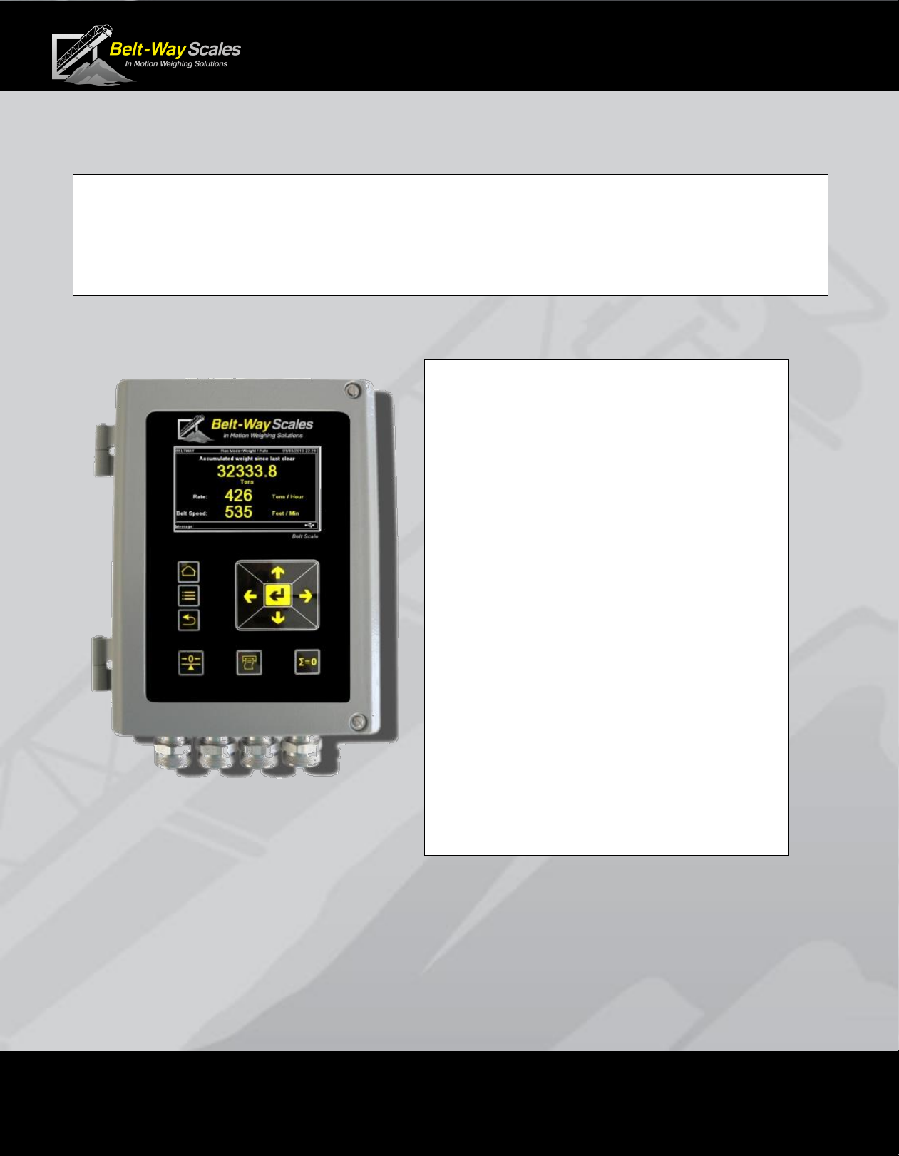
Integrator Specifications
Replacement Part Number: BWINT
100-240 AC Power Supply Factory Installed Part Number: BWPS-AC
100-240 AC Power Supply Field Installation Kit Part Number: BWPSKIT
IO Option Board Part Number: BWIO (Factory Installed)
IO Option Board Kit Part Number: BWIOKIT (Field Installed)
Display: 4.3" Color LCD
Enclosure: Cast Aluminum
Operating Temperature: -20C to 45C
Required Power: 12-24 VDC, 55 Watts
optional 110/240 AC power adapter
Inputs: 8 Load Cells (millivolts)
1 Speed Sensor (0-5 VDC Pulse)
1 Angle Sensor (0- 4 VDC)
Outputs: 1 RS232 (Printer Port)
1 RS232 (Display Port)
1 Ethernet Port (Modbus TCP)
1 USB 2.0 Client
Optional IO Outputs:
4-20 mA outputs (Tons Per Hour)
Digital Pulsed Output (Total Weight)
Min / Max Speed
Min / Max Tons Per Hour
Zero Calibration
Loadout
Optional IO Inputs:
Clear Weight
Print Ticket
Zero Calibration
Phone: (815) 625-5573 beltwayscales.com sales@beltwayscales.com
Page 8 of 44
Conveyor Belt Scale
Product Manual
Electrical Ratings
Input Power to
Belt-Way Integrator:
12-30 VDC, 24 VDC 2.25A Max
AC Power option:
Input:100-240VAC 50/60Hz, 1A Max
Output: 24VDC, 2.25A Max
Use of the factory supplied AC Power option is recommended.
AC control power over-current protection with isolated circuit, and
disconnect point such as a breaker or switch box, is recommended
Conformance to local electrical codes is required.
Digital Inputs: (IO
option installed)
12-24VDC, 50mA sink
Digital Outputs: (IO
option installed)
12 - 24VDC, 100mA sink
Analog Outputs: (IO
option installed)
4-20mA, 24VDC powered loop
Relay Outputs, UL
contact ratings:
(IO option installed)
220VDC, 0.24A, 60W
125VDC, 0.24A, 30W
250VAC, 0.25A, 62.5VA
125VAC, 0.5A, 62.5VA
30VDC, 2A, 60W
Environmental
▪ Temperature: Normal operating range -20⁰C to +45 ⁰C.
▪ Humidity: The unit is suitable for outdoor use.
▪ Altitude: The unit is suitable for use to elevation of 2000m.
Phone: (815) 625-5573 beltwayscales.com sales@beltwayscales.com
Page 9 of 44
Conveyor Belt Scale
Product Manual
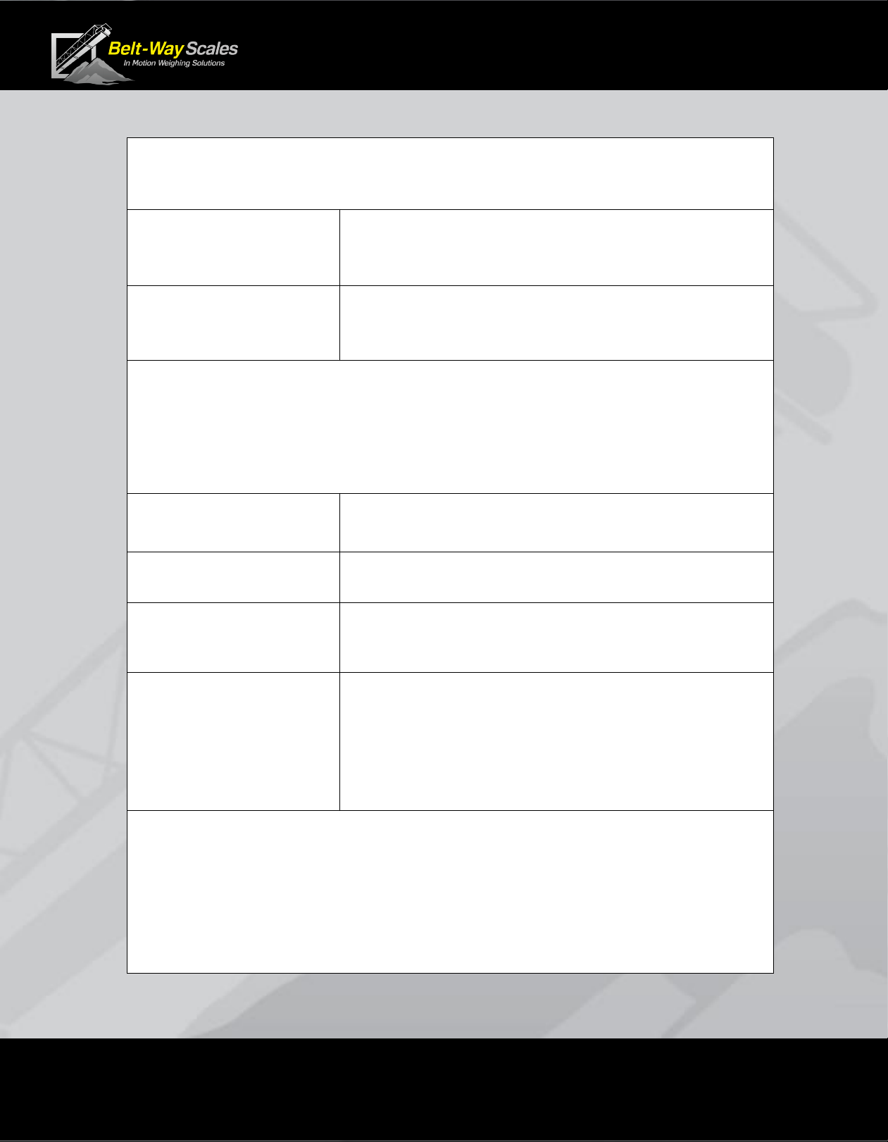
Scale Components
The single idler scale consists of the following components
1 - Integrator
2 - Load Cell
Assemblies
2 - Mounting pipes
1- Hardware Kit
1 - Speed Sensor with
mounting arm
The dual idler scale consists of the following components
1 - Integrator
4 - Load Cell
Assemblies
4 - Mounting pipes
2 – Hardware Kits
1 - Speed Sensor with
mounting arm
Unpacking the Scale
Each scale is comprised of at least three boxes
26” x 10” x 8” - Integrator and Speed Sensor
26” x 10” x 8” - Load Cells and Hardware kit
48”, 60” or 72” long boxes for mounting pipe
and various sizes for angle sensors and other accessories
Phone: (815) 625-5573 beltwayscales.com sales@beltwayscales.com
Page 10 of 44
Conveyor Belt Scale
Product Manual
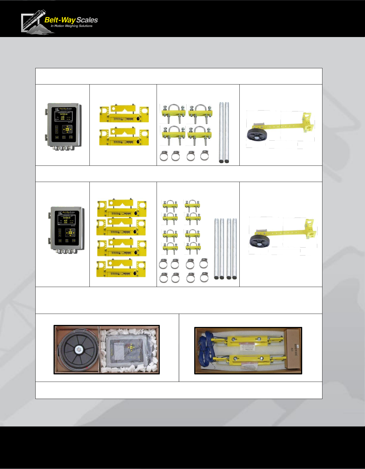
Mechanical Installation
2D component and installation drawings are available at beltwayscales.com
3D drawings are available by request.
A. Recommended Tools
▪ Cutting torch and grinder (remove idler mounting feet)
▪ Heavy duty drill or magnetic drill press (drill u-bolt holes)
▪ Tape Measure (measure idler distance)
▪ Angle finder or phone app (measure conveyor angle)
▪ 1/2” socket and wrench (load cell and speed sensor brackets)
▪ 9/16” deep socket and wrench (V-block, u-bolts, leveling bolts)
▪ String (to level weighbridge idlers)
▪ Shim kit (to adjust idler height)
▪ 4 way screwdriver (integrator mounting, integrator door, hose clamps)
▪ Small Belt-way screwdriver (integrator wiring)
B. Conveyor Design Recommendations
The following design suggestions are essential for best scale accuracy and repeatability.
▪ Reduce speed whenever possible to maximize belt load. Slow moving, heavily loaded belts
work better than fast moving, lightly loaded belts.
▪ Proper belt tension must result in 1%-2% deflection between idlers.
For example, 2% deflection is 1 inch sag in the belt over a 4 ft. idler spacing.
▪ Lower trough angles, 0-35, are preferred. Avoid 45 troughed idlers.
▪ Install a belt scraper to keep the belt clean.
▪ Cover the conveyor to shelter it from wind, rain and snow.
MOUNTING PIPE
AND
LEVELING
PLATES
MODIFIED
CEMA IDLER
LOAD CELL
ASSEMBLIES
SPEED
SENSOR
V-Block
CONVEYOR
FRAME
Phone: (815) 625-5573 beltwayscales.com sales@beltwayscales.com
Page 11 of 44
Conveyor Belt Scale
Product Manual
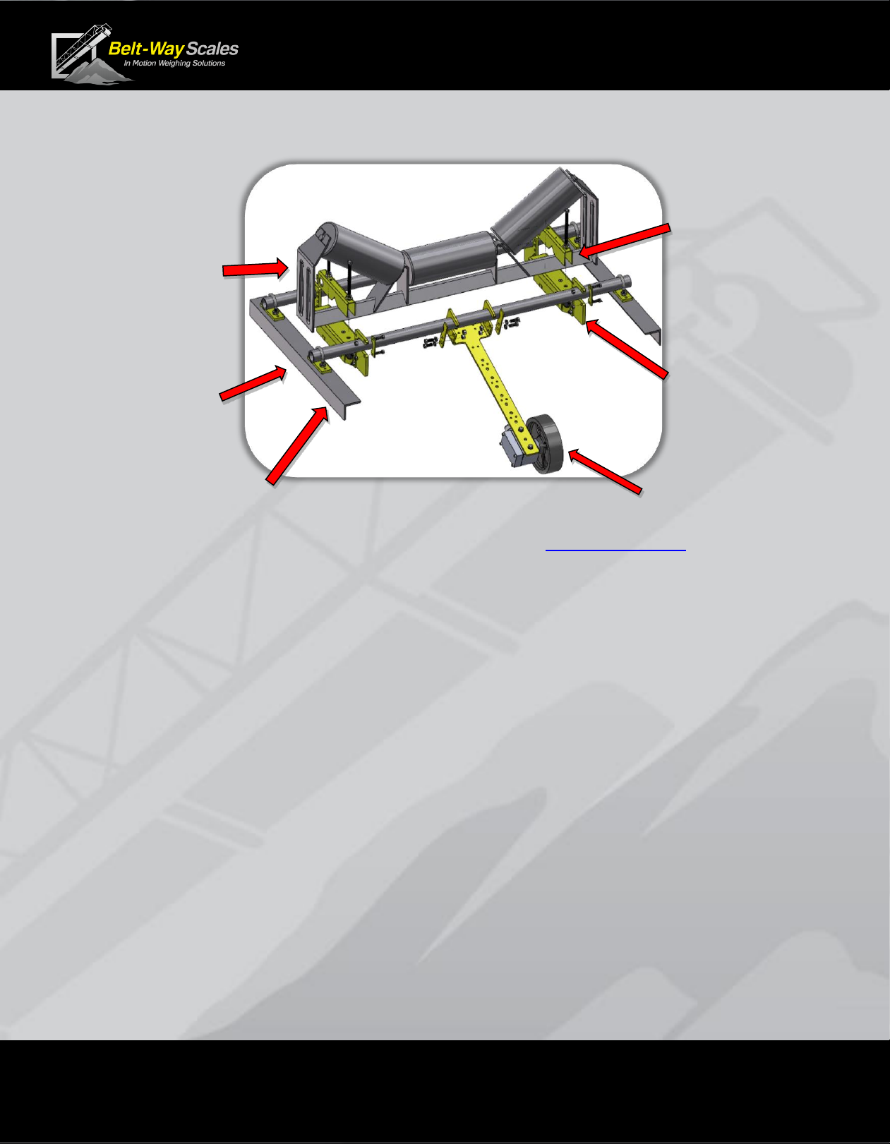
C. Scale Placement
▪ Install the scale where it is easily accessible for maintenance purposes.
▪ Choose a very rigid section of conveyor such as an idler over a brace.
▪ Avoid curves in the conveyor.
▪ Stay at least three idlers away from the head pulley, tail pulley, and loading points.
Material must not impact the belt near the scale!
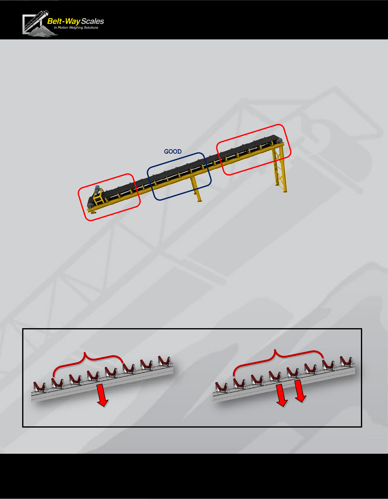
D. Define the Weighbridge
▪ The weighbridge idlers must be in good mechanical condition.
▪ The weighbridge idlers must be the same trough angle, and diameter.
▪ The weighbridge idlers should be an equal distance apart.
▪ Skirting should not make contact with the belt in the weighing area.
▪ A single idler weighbridge consists of 5 idlers.
Scale must be installed on the center idler
▪ The dual idler weighbridge consists of 6 idlers.
The scale must be installed on the 2 center idlers.
GOOD
AVOID
AVOID
5 Idler Weighbridge
Single Idler Scale
6 Idler Weighbridge
Dual Idler Scale
Phone: (815) 625-5573 beltwayscales.com sales@beltwayscales.com
Page 12 of 44
Conveyor Belt Scale
Product Manual
E. Attach Load Cell Assemblies to idler
▪ Bolt the load cell assemblies to the idler as shown using the “V-Block”.
▪ The load cell cable should point downhill.
▪ Leave plenty of clearance between the load cell assembly and conveyor frame.
▪ Do not overtighten the V-Block bolts.
▪ The bolts should be tightened ¼ turn after compressing the lock washer.
▪ Position the load cell assemblies an equal distance from the conveyor frame.
▪ This balances the load of the belt evenly between the load cells.
NOTE: Stainless Steel Load Cells – Do not use a full thread bolt,
or over tighten the existing V-Block bolt on a stainless steel load cell.
This will damage the load cell cable.
Phone: (815) 625-5573 beltwayscales.com sales@beltwayscales.com
Page 13 of 44
Conveyor Belt Scale
Product Manual
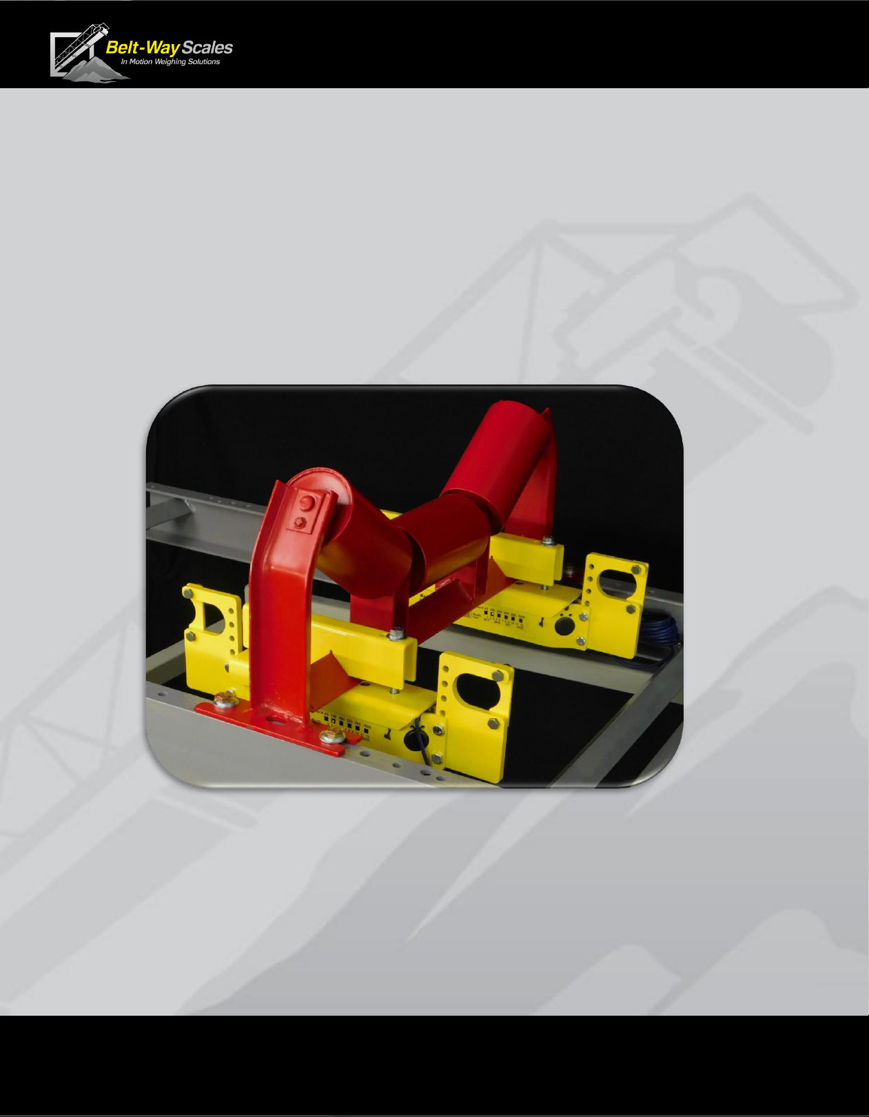
F. Install Scale Support Pipes
This step is extremely important to ensure long term scale accuracy.
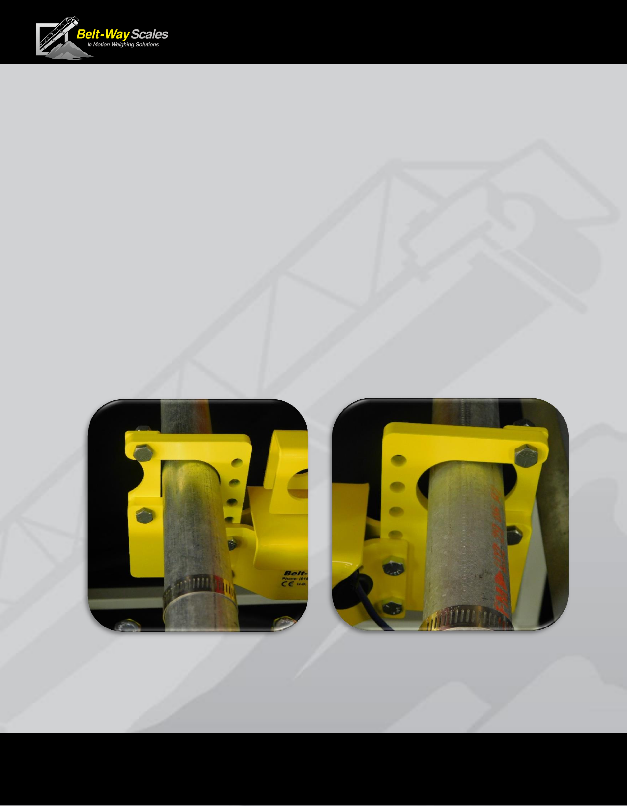
▪ The mounting pipe must touch the strap on the uphill side of load cell assembly.
▪ The strap on the downhill side must create an oval opening.
▪ Center the pipe in the oval hole.
▪ The load cell assembly must be free to move up and down slightly on the pipes.
This eliminates torque on the conveyor frame, which allows automatic alignment
of the weighing elements.
▪ Install the four hose clamps onto the pipe with the screw fitting directly over the
top of the pipe, but do not tighten the clamps at this time.
Uphill side:
Retaining strap
fits tightly around the pipe.
Downhill side:
Retaining strap
forms oval hole around the pipe.
Phone: (815) 625-5573 beltwayscales.com sales@beltwayscales.com
Page 14 of 44
Conveyor Belt Scale
Product Manual
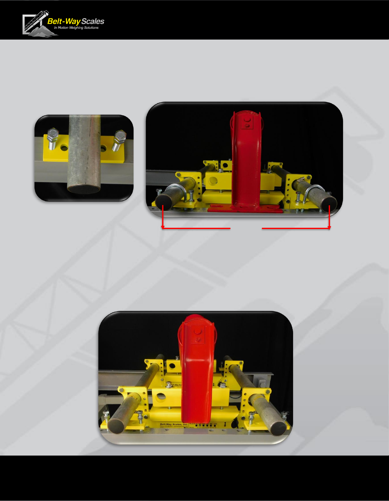
G. Drill U-bolt Holes
▪ Use the leveling plate as a drill template for the U-bolts.
▪ The centers of the leveling plates and pipes should measure 15” apart.
▪ The holes should be at least 7/ 16 ” to clear the 3/8” -16 U-bolts.
H. Remove and Modify Idler
▪ Unbolt idler from frame.
▪ Remove the idler mounting feet to create clearance above the conveyor frame.
▪ If the idler feet are not removed, all other weighbridge idlers must be shimmed up 3/8”.
▪ Ensure the idler is centered on the conveyor.
15”
 Loading...