

Page 1
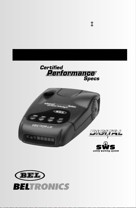
Vec tor LR
RADAR•LASER•SAFETY DETECTOR
Operating instructions for model 970
Advanced
PRO TECTION
System
TM
with Shadow Technology
®
®®®®
DIGITAL PLL SYNTHESIZED
OSCILLATOR
TM
Page 2

introduction
Thank you for purchasing a vector l r Radar/Laser/Safety
detector with the Advanced Protection System™and Shadow
Technology®II.vect or l r is a new dimension in detection
technology. Desig ned for the professional driver vector l on g
range emphasizes ultimate performance in a detector with
Certified Performance Specs and is selected for premium
performance and reliability.
Remember,owning a Radar detector does not give you a license to
speed.Alerts from a Radar detector serve as an effective reminder to
check your speed.Laws vary throughout North America governing the
use of a Radar detector.It is your responsibility to follow these laws.
software upgrade– an industry first
vecto r lr contains technology which provides the highest
capability to be reprogrammed as the threat ofnew Police traffic
Radar monitoring technologies emerge. Please ensure that you
promptly mail the enclosed Consumer Information card. This w ill
ensure you are notified about new,approved traffic monitoring
technologies and will be provided the details ofserv ice cost and
where to send your unit for software upgrade.
shadow technolog y®ii
vecto r lr contai ns Shad ow Technology®,making it undetectable
to the Interceptor vg-2or any other Radar Detector Detector (rdd).
Only Shadow Technology®IIhas been consistently proven
undetectable to the vg-2.
selectable features
These features may be selected depending upon your driving
environment.(See page 9 for the operating of Selectable
Features.)
City X or City All
X/K/Ka Band on or off
Auto-Mute on or off
Safety Warning Sys t em
®
on or off
Audio/Visual Scroll Rate (fast or slo w)
Page 3

table of con ten ts
Profile of Features lpage4
Description of Features
l
page5
Power-Up Test Sequence/Start-up Mode lpage5
Tutori al M odelpage 6
Set and Forget Memorylpage7
Reset to Factory Settingslpage7
drk (Brig ht/Dim/Dark) Button lpage7
aud (Auto-Mute/Volume Control) Button lpage8
cty(City/Highway) Button lpage8
Selectable Features
l
page9
Entering Selectable Features Modelpage11
Installation
l
page11
General Guidelineslpage11
Understanding Radar,Laser and sws
™
l
page14
Interpretation ofAlerts
l
page15
Radar Alerts lpage15
Instant-On/Pulsed Radar Alert lpage18
Typical False Alert (Radar) lpage18
Laser Alertslpage18
Safety Warning System®(sws™)Alertslpage19
Performance Verification
l
page
Conditions That Affect Radar Alerts lpage
Conditions That Affect Laser Alerts lpage20
Troubleshooting
l
page21
Consumer Warranty
l
page21
Service
l
page22
Warranty Service lpage22
Post-Warranty S er v icelpage23
Accessories
l
page23
Page 4
profile of features
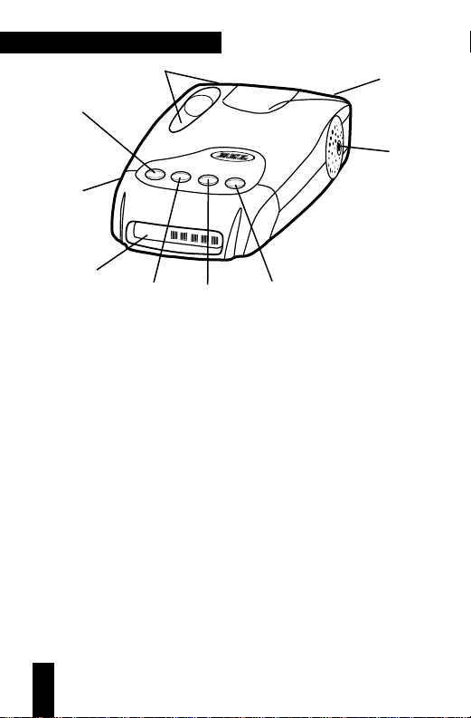
1. pwr(Power/Start-Up Mode) Button:pressing and hol di n g
pwr will turn the unit on.Releasing and pressing the pwr
button again will scroll through the five Start-Up mode
options:
NORMAL,MODS
(Modifications),
Q-START
(Quick
Start)
TECH MODE, VOLTAGE METER
plus
TUTORIAL MODE.
2 Text Message Display:communicates all mode selections
(i.e.
DIM,DARK,CITY
and
HIGHWAY
)and confirms Radar
band and signal strength,presence ofLaser and sws
™
messages received.
3. drk (Bright/Dim/Dark)Button:provides bright,dark an d
fully adjustable dim settings of the Text Display for discreet
night travel.Audio alerts are notaffected.
4. aud (Audio Mute/Volume Control) Button:provides manua l
muting ofall Radar and sws
™
alerts.Pressing and holding the
aud button will change the audio level.
5. cty(City/Highway) Button:choose between Highway mode
or for urban/suburban travel,City X or City All modes.
6. Antenna Opening:Radar and sws
™
signals are received by
a patented diecast antenna with integrated transition to
microstrip mixer.
PWR DRK AUD CTY
International
V
EC
TO
R
LR
Advanced Protection System
with Shadow Technology II
K
a
9
7
2
4
1
9
6
3
5
8
Page 5

7. Laser Optical Sensors:collect Laser signals from in front and
behind.
8. Audio Alert Speaker: all audible alerts are emitted from this
location.
9. Power Jack:using the straight or coiled cord,vecto r l r
operates in any vehicle with a 13.8 volt dc negative ground
system (10.5 volt to 16 volt range).
description of features
Power-Up Test Sequence/Start-up Mode
Each time your detector is turned on,vector l r will perform
a power-up test sequence based upon the Start-Up mode
selected.There are five Start-Up modes ofoperation plus a
Tutorial mode. Release the pwr button at your chosen selection.
Note—Pressing pwr at any time during Start-Up will bypass
the sequence.
NORMAL (Factory pre-set Mode)
PresentsAudio and Text Messages for Laser,Ka,K, X and Safet y
Warning System® (sws
™
).After this sequence,the status of
Selectable Features is displayed:
“
CTY X” or “CTYALL”;“X/K/KA BAND o n /o f f ”;
“ Automute o n /o ff”;“SWS o n ”,“SWS o f f ”;
“SCROLf a s t ”,SCROLslow”. Unit is no w rea dy fo r
operation.
MODS (Modifications Mode)
Presents Audio and Text Messages for Laser,Ka,K,X,and
Safety Warning System® followed by the presentation of
Selectable Features as chosen by the user.
Q-START (Quick-Start Mode)
Unit will bypass any form ofa power-up test sequence and
will display
CITY orHIGHWAY depending upon the mode
previously selected.Unit is ready for operation.
Page 6

TECH MODE
Presents Audio,Text Messages and frequency readout for
Laser,Ka,K,X,and Safety Warning System®.After this test
sequence,the status of Selectable Features is displayed. Tech
Mode gives you the benefit ofidentify ing Radar bands and
Laser coupled with the actual frequency received.See sample
messages below:
LASER 900NM; KA 33.4; K 21.150; X 10.525
VOLTAGE METER MODE
Presents a continuous, dig ital readout of your vehicle’s batter y
voltage (10.5 to 16 volt range).Voltage Meter Mode lets you
know if power to your unit falls below 10.5 volts and
consequently, impedes performance to your unit. While
operating in Voltage Meter Mode,your unit will display the
“C”or“H”confirming City or Highway mode,and will
provide full alerts to Radar,Laser and SWSTMwhen
encountered,while continuously monitoring your battery
voltage.Ifvoltage rises above 16.0, the display will flash
“HI VOLT” until condition is rectified.Ifvoltage falls below
10.5 volts,display will flash “LOW VOLT” until condition is
rectified.
TUTORIAL MODE
The tutorial mode allows you to become more familiar with
all audible and visual alerts.The message “TUTORIAL”
appears in the display followed by the audio and
corresponding Text Message for “LASER”,“Ka AUDIO”,
“K AUDIO”,“X AUDIO”, sample Radar alert (K band signal
ramping from weak to strong) and “SAFETY WARNING
SYSTEM SAMPLE ALERTS”.Three samplesws
™
messages are
then presented in the display along with the corresponding
Audio Alert:
Sample 1 “
ACCIDENT AHEAD”
Sample 2 “HIGHWAY WORKCREW AHEAD”
Sample 3 “POLICE IN PURSUIT”
While sample messages are playing you can access the
complete list of sws™messages by pressing the ctybutton to
Page 7

move forward in the list.“MSG 1” will appear in the display
confirming your selection (to move backward in the list,press
the drk button).Pressing the aud button allows you to vi ew
the sws™message in the display. Press the cty button again to
step to the next message;press the aud button to review,and
so on.This allows you to review all 60messages.
To e xit Tu torial Mo de, p res s the pwr button and your u ni t
will be onand ready to receive signals.
Set and Forget Memory
Any time vector lris turned off or unplugged from the
cigarette lighter socket,all feature settings you have selected are
retainedin the unit’s memory.Set and Forget Memory
eliminates the need to reset your preferred feature settings
each time your unit is turned offand then back on.
Reset to Factory Settings
You can reset your unit to factory settings for Start-Up Mode,
volume,drk,aud,ctyand Selectable Features.To reset, press
and hold the cty button until the displayshows “
RESET”.
Two “beeps”will sound and your unit will cycle through the
NORMAL Start-Up mode and be on and ready for operation.
drk (Bright/Dim/Dark) Button
The drk button allows selection of a bright,fully adjustable
dim mode or dark mode.The unit is factory preset to full
bright d i spl ay.To engage dimmode,press and hold the drk
button.The display will cycle through various levels of dim
illumination.Release the button at your chosen level. To
engage dark mode,press the drkbutton a second time.A
single “beep” coupled with the brief illumination of“
DARK”
on the display confirms your selection.You’ll notice an “H”
(Highway mode) or “C”(City mode) remains dim to confirm
your unit is receiving power. To return to a full bright setting,
press the drk button a third time;two “beeps”confirm this
selection.Use ofthe drkbutton does not affect audio alerts.
Important—ifyou press the the drkbutton and do not receive
audible confirmation,the audio level has been set too low.
Page 8

aud (Auto-Mute/Volume Control) Button
Manual Muting ofAudio Alerts (Radar and sws
™
)
Whether Auto-Mute is selected on or off in Selectable
Features,the audio alerts can be completely muted by
pressing the aud button during an alert.The display will
briefly sh ow “
Qu i e t .”.No audible alert will be heard for
approximately 12 seconds.If the signal is still present after 12
seconds,the unit will remain in manual mute mode.
Note—because Laser alerts are not lengthy or sustained,muting
is not required (see page )
Volume Cont rol
Press and hold the aud button to engage th e volu me cont rol.
The Audio level has 9 settings.Release the aud button when
you have reached your desired audio setting.
cty (City/Highway) Button
The cty mode has been designed to effectively reduce
unwanted audio alerts caused by intrusion alarms,door
openers,and other devices which share X band with police
Radar—without reducing sensitivity.Signals from non-police
Radar sources are frequently encountered in urban and suburban areas,making use ofthis mode ideal in these areas.
Pressing the cty button once engages the cty mode which is
confirmed by “
CITY”in the display coupled with a single audio
“beep”. Pressing the ctybutton a second time returns you to
highway mode;“HI GHWAY”will appear in the display coupled
with two“beeps”.Once engaged,weak X band signals
encounteredwill produce no audible alert until the signal
strength reaches a preset level.However,visual alerts are
processed the instant an X band signal is detected,keeping
you quietly informed.Since most “false”X band signals are
weak,the use ofthe cty mode allows you to drive out oftheir
range before they reach the preset level and trigger a full
audio alert.In contrast, sig nals from X band traffic Radar are
generally stronger and will exceed the preset level, causing a
full X bandaudio alert.Activating the ctymode will not
Page 9

change Super Wideband Ka,K or instant-on X band Radar
alert patterns.
Note—the cty mode does not change the presentation of alerts
for Laser or sws
™
.
City All
City All mode is a Selectable Feature ofthe vec t or l r
(see Selectable Features page 9). This feature provides an
alternate approach for i mproving selectivity on X,K and
Super Wideband Ka and is ideal for use in areas with a high
level ofmicrowave transmissions which can cause falsing on
all Radar bands.
While i n C i ty All mode,vector lr will provide an initial
short X,K,or Ka audio alert coupled with visual confirmation
ofthe band detected and signal strength in the display.No
further audible alert is provideduntil the signal strength
reaches a preset level.When no audio alert is provided, the
visual alert keepsyou quietly informed.
Note—Once “
CTY X”or “CTY ALL”is chosen in Selectable
Featu re s t he ctybutton must to be pressed to engage your
selection.
selectable features
The following features may be selecteddepending upon your
driving environment and preference.
City X or City All
X/K/Ka Band on or off
Auto-Mute on or off
Safety W a rning Sy s tem®on or off
Audio/Visual Scroll Rate (fast or slow)
City X or City All
When “
CTY X ”is selected,your unit provides standard X
Band selectivity which is suitable for most urban areas.
City All provides an increas ed level of selectivity on all Bands
Page 10

and is designed for use in high density microwave areas.
Factory setting is “CTY X ”.
Note—once “
CTY X”or “CTY ALL”is chosen in
Selectable Features,the cty button must be pressed to engage
your select io n.
X/K/Ka Band On or Off
Select “X on/X off”,“K on/K off”or “Ka o n /Ka o f f”
depending upon your driving environment and selectivity
requirements.This mode is especially useful where falsing
may occur and disabling the offending band may be required.
Factory setting is on for all three Bands.
Auto-Mute On/Off
With “Amute on ”,unit will provide several X,K,Super
Wideband Ka audio alerts.After the audio alerts,a “clicking”
tone keeps you quietly informed for as long as the signal is
present.This clicking becomes more rapid as the strength of
the Radar signal increases.“Amute on”enables you to
conveniently monitor extende d e ncou nters w it hout hav i ng to
manually mute or adjust the volume setting.
With “
Amuteoff,” unit will provide a continuous series of
X,K,Super Wideband Ka and Laser audio alerts. This
standard setting is often preferred when background noise in a
vehicle is loud. Factor y sett ing is “Amu teoff.”
Note:because of their urgency,Laser alerts are not affected.
Safety Warning System
®
(sws™)
When on,unit will provide a Message when signals from sws
™
transmitters are dete cted.Factory setting is on.
Audio/Visual Scroll Rate
When “
SCRLslow” is s e lected,unit will provide a slow cycling
ofaudio/visual messages.When “SCRLfa s t ”is selected,unit
will provide a fast cycling ofaudio/visual messages.Factory
setting is“SCRLslow.”
Page 11

Instaclear is a registered trademark of t he Ford Motor Company.
ElectriClear is a registered Trademark of Libbey,Owens,Ford,and Delco-Remy.
Entering Selectable Features Mode
1. With the unit off,press and hold the cty button,then press
the pwr button.The word “
FEATURES”will appear in the
display and a short audible “beep”w ill sound indicating you
are now in the Selectable Features Mode.
2. Immediately after the “beep”, the display will show the status
of the first Selectable Feature (City X or City All).
3. Press t he aud button to make your selection. Press the cty
button to move to the next Selectable Feature.Repeat the
process until you have made your selection for each
Selectable Feature.
4. Press the pwr button to exit Selectable Features mode.Two
“beeps” confirm that you have exited this mode and either
“
HI GHWAY”o r “ CITY”will be presented in the display,based
on your previous selection.Your unit is ready for operation.
installation
General Guidelines
Do not mount your unit directly behind windshield wipers or
mirrored sunscreens which block Radar and Laser signals
and substantially reduce warning range.Unlike “after market”
mirrored sun-screens,regular tinted glass does not affect
Radar reception. Radar signals are also reflected by the “heated
windshields”known as Instaclear
®
and ElectriClear®available
as an option on some vehicles.This type of windshield makes
any dash,visor or windshield mounted detector ineffective.
(If in doubt,check with an appropriate dealership to see if
this applies to your vehicle.) To achieve optimum performance,
regardless of whi c h mountin g positi o n yo u c h oose,follow the
basic steps on the following page:
1. Consider occupant safety when selecting a mounting location.
Choose a location where the unit will not be hazardous in
case of an accident.
Page 12
2. For optimum de te c t i on , position your unit w it h a cl e ar,
unobstructed view ofthe road from thefront and rear.
3. Do not allow the unit to make contact with the windshield.
This will eliminate unnecessary vibration.
4. Avoid placing your unit in direct sunlight.During the summer,
interior temperatures ofan enclosed vehicle can sometimes
reach temperatures that will cause premature aging ofthe unit.
5. Your detector is not waterproof;exposure to water may cause
damage and your warrant will be void.
Dash Mounting
You can mount your unit to a level area ofyour vehicle’s dash
using the hook and loop fastener or the four,non-skid dash
mounting pads provided.
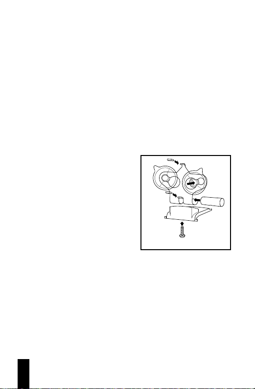
Win dshield Br acket Assembly
The visor clip is fully
assembled.To assemble the
windshield bracket,follow this
diagram.
Win dshield Mounting
1. Remove t he mounti n g bracket
cover on top ofthe unit by
pressing on the raised dots
and pushing outward.Store
the cover in a safe place.
2. Clean the selec ted windshield area,position the suction-cup
mount on the windshield,and press firmly on each suction
cup to secure it in place.
3. Use a screwdriver or a small coin to adjust the angle ofthe
suction-cup mount until the base plate is level.
Wind shield B racket As sembly
Page 13
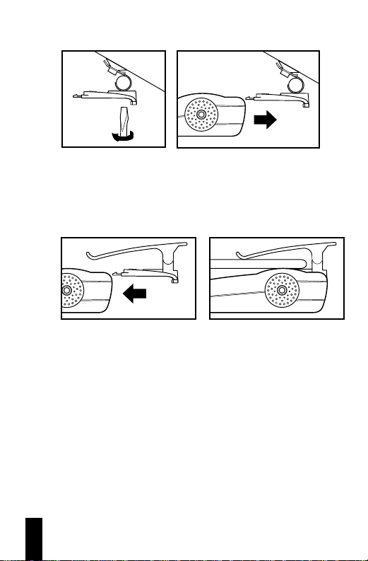
4. Slide detector onto base plate until it snaps into place.
Note—some vehicles have a plastic coating on the inside ofthe
windshield designed to protect occupants in case of an accident.
Use ofthe w ind shield bracket on this ty pe of windshield can
permanently mark the surface.Check with your dealer ifyou
are unsure whether your vehicle is equipped with this type of
windshield.
Visor Moun ting
1. Remove the mounting bracket cover by pressing on the
raised dots and pushing outward.Store the cover in a
safe place.
2. Slide the visor clip onto the top ofthe detector until it snaps
into place.Clip the de te ctor to the edge of the sun visor nearest
the windshield.
Fuse Replacement
1. If the fuse has blown,remove the tip from the lighter plug
followed by the old fuse.Replace the fuse with a 1-amp,3AG
fuse.Defeating the fuse protection can damage your unit or
your vehicle’s electrical system and will void your warranty.
Page 14
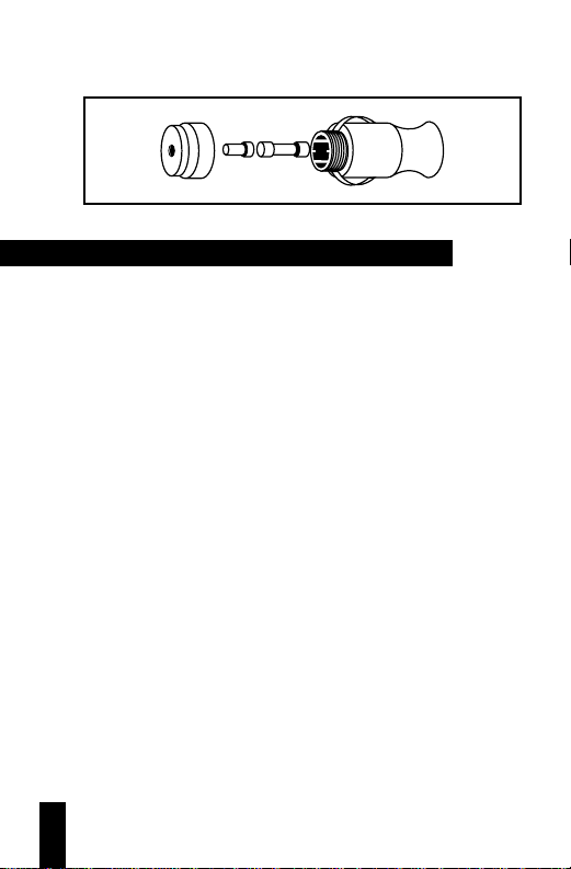
Note—the tip is in two pieces;be careful not to lose either piece
or the spring inside the holder.(See diagram below).
understanding radar,laser and sws
™
Three Radar Frequencies
Three microwave frequencies have been allocated by the fcc
(Federal Communications Commission) and are used for
traffic Radar.They are:
X band:10.525 gh
z
K band:24.150 ghz
Super Wideband Ka:33.4 ghzto 36.0 ghz
Both X and K bands are well known to motorists who have
traveled with Radar detectors.Introduced first was X band
Radar which became common during the 1960s.In the mid
1970s the lower powered,more difficult to detect K band Radar
was introduced. In 1987,fcc approval was given for Radar
equipment using a third frequency,Ka.In response to this,
beltronicsintroduced the first Radar detectors capable of
detecting X,K and Ka band signals.In late 1990,fccapproval
was given to Wideba nd Ka : 34.2ghz to 35.2 ghz.Once again,
belresponded with Wideband Ka detection. Today,
vecto r lr detects the completeSuper Wideband Ka frequency
allotted for police monitoring—33.4 ghzto 36.0 ghz.
Total Tracking Laser
™
(ttl™)
Unlike Radar signals,which are highly reflective,Laser signals
have very poor re flective charac t e ristics . Many of today’s
Laser detectors do not have the high sensitivity necessary to
detect Laser within a large “field ofview”.vector lr
incorporates bel’snumber one rated Laser detection. Twin
Page 15
Laser ports detect energy far outside the main Laser beam—
including off-axis signals—providing the largest achievable
360°“field ofview.”The alerts provided by your unit are the
same whether signals are received from the front or rear.
Safety Warning Syst em
®
(sws™)—What is it?
The Radio Association Defending Airwave Rights,Inc.
(r.a.d.a.r.)conceived and d evel ope d t he Sa fety Warning
System
®
.The concept behind this system is to warn motorists
ofpotential road hazards by employing Safety Warning System
®
transmitters in areas such as construction zones,accident
sites and detours. These sws™transmitters operate within
the 24ghz portion ofthe K band frequency, and broadcast
uniquely coded signals that are detected by your unit.
interpretation of alerts
Radar Alerts
The alerts provided by your unit are affected both by the type
of t ransmission (continuous wave or instant-on),and the
position ofthe Radar source.Generally,when you drive closer
to a Radar source,the intensity of the received signal increases,
resulting in the increase of the number of bar graph segments
as well as numerical digit [1–9]and a corresponding increase
in the audio alert rate.Described below are five common
types of Radar encounters and the alerts you will typically
receive.
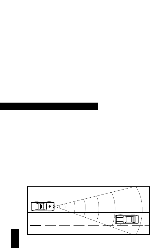
1. Stationary or moving Radar,straight ahead aimed in your
direction.
Page 16
Since Radar signals travel in a straight line,this Radar
encounter potentially offers maximum warning range.Once
the signal is received,the initial warning consists of an X, K or
Super Wideband Ka audi o a l ert coupled with si mult a ne ou s
identification ofthe Radar band (X,K or Ka) and signal
strength in the Text Display.The number of bar graph segments
displayed depends upon the strength of the signal received.As
the strength ofthe Radar signal increases,the audio alert
becomes more rapid and the bar graph will display the
maximum number offive segments and the digit “9”will also
appear indicating maximum signal strength.Assuming the
Radar signal remains uninterrupted,the audible and visual
alerts will clearly indicate a “weak”signal becoming stronger
as you drive closer to the Radar source.Remember,when the
police Radar source is moving toward you,the Radar signal
strength will increase much more rapidly than ifyou are
approaching a stationary source.
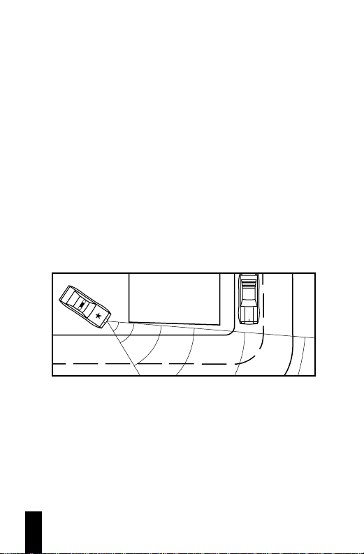
2. Stationary Radar aimed around a corner
Under this circumstance,reaction time is considerably
reduced. Since the Radar signals are transmitted acrossyour
line of travel,there is generally no signal available to receive
until you are relatively close to the source.Once an alert is
received, expect the strength of the signal to increase very
quickly.Advanced warning in this situation may be reduced.
Page 17
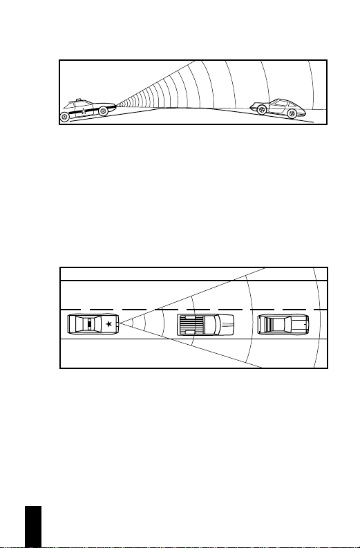
3. Stationary Radar concealed by the crest ofa hill aimed in your
direction.
Radar signals travel in a straight line and do not pass through
earth.Consequently,police Radar aimed at the crest ofa steep
hill cannot be received until you are at or near the top.
Warning time may be minimal (as in situation #2) since a
strong signal is not present until you are near the crest of the
hill.At this point,you may be nearly in the police officer’s line
of sig ht.When cresting a hill,a weak initial alert followed very
quickly by a full alert is typical.This alert pattern requires
prompt attention .
4. Moving Radar behind you,traveling in the same direction.
Police Radar signals transmitted from behind your vehicle
canbe received when reflected by objects in front ofyou
such as large signs,bridges and trucks.As you drive,the size
and configuration ofthese objects are constantly changing
causingth e strength of any reflected Radar signal received to
vary.A strong,uninterrupted alert indicates the patrol car is
close behind.
Page 18

Instant-On/Pulsed Radar
This type ofsignal appears suddenly when a Radar unit is
“triggered”.The instant-on alert consists ofan intense,three
second audio “burst”,coupled with the type ofband detected
and flashing ofthe signal strength bar graph in the display.
Instant-on/pulsed alert to Ka band
Ka 9
Typical False Alert (Radar)
Ideally,a Radar detector should only alert in the presence of
police Radar.However,because other devices share X band
with police Radar,false alerts sometimes occur. Generally,a
false signal produces only a short audio and visual alert.Since
they are most often weak,it is possible to drive out ofthe
signal’s range very quickly and receive only a briefaler t.
Although many times the probable source ofthe false signal
can be identified (supermarket,bank,commercial building,
etc.),caution is advised until the source can be confirmed.
The X band alert pattern caused by a non-police source can
look like the initial alert produced by actual police Radar.
For this reason appropriate action is required any time an
alert is received.
Laser Alerts
When Laser is detected,the display will flash “
LASER”
coupled with a distinc t Laser audio alert. If a vehicle is a long
distance from the source ofLaser pulses,fewer pulses will
generally be received.The closer the vehicle is to the source of
Laser pulses,the greater the likelihood ofreceiving a steady
stream ofLaser pulses.The reason for this is the aiming
stability ofthe Laser gun and the fact that it is difficult to hold
the gun absolutely sti ll .Any movement of the gun results in
motion ofthe beam at the target.The furtherthe target,the
greater the displacement ofthe beam and the shorter the dwell
time of the beam at the target point.Therefore,there is the
possibility ofreceiving only a few Laser pulses.Due to these
characteristics,all Laser alerts should be taken seriously.
Page 19

Safety Warning Syst em®(sws™) Alerts
With the Safety Warning System
®
feature onand an sws
™
transmitter in use,your detector will provide a unique,2 seco nd
sws™tone coupled w it h a S afe t y Warning System®category
word (i.e.“Hazd Zone ”indicating Highway Hazard Zone
Advisory) to quickly orient you to the type of situation
ahead.This introductory message is followed by a specific Text
Message (i.e.“SHARP CURVE AHEAD”) The display will
continue to present the message and provide the “clicking”
tone for as long as an sw s™signal is detected.Iftwo separate
sws™messages are received,each message is presented twice
before the “beeps”resume.
You can replay the lastsws
™
message received by pressing
the drk buttonwithin 30 seconds of receiving an sws™alert.
Note—the end of a multiple word sws
™
message is indicated by
an aster i sk .
Abbreviated sws™Category Wor ds
“
Hw y Wo r k ”
confirms Highway Construction/Maintenance
(messages 1–11)
“
Ha z d Zo n e ”
confirms Highway Hazard Zone Advisory
(messages 13–31)
“
Weather”
confirms Weather Related Hazards
(messages 33–41)
“
Tr a v In f o ”
confirms Travel Information/Convenience
(messages 43–59)
“
Movin g”
confirms Emergency/Slow Moving Vehicles in t ransit
(messages 61–64)
“
Messag eUn known”
confirms incomplete or unknown messages
Page 20

Note—for a complete listing of the five Safety WarningSystem
®
categories and corresponding messages,please refer to the Safety
Wa rning Syst em®Alert Card enclosed with your manual.
performance verification
Conditions that Affect Radar Alerts
Ifyou feel your unit is not alerting properly,keep in mind that
there are many conditions that influence the intensity or
durati on of an a le rt:
1. The police are using instant-on/pulsed Radar, in which case
no signal is transmitted until visual contact has been made
with your vehicle. For detection of this signal,you must rely
on reflected signals from Radar directed at traffic traveling
ahead ofyou.
2. The police Radar unit is positioned perpendicular to the road,
around a curve,or just over the crest ofa hill thus significantly
reducing the reception range.
3. The highway traffic between your vehicle and the police Radar
source is heavy.This blocks/reflects transmitted signals. The
presence ofseveral large trucks between you and the police
Radar unit could also significantly reduce reception.
4. Rain or humid weather conditions can absorb transmitted
signalsbefore they reach your vehicle,again reducing detection
range.
5. The police Radar unit is not properly tuned and is transmitting
outside the fccallocated X,K or Super Wideband Ka frequency
ranges.
Conditions that Affect Laser Alerts
Ifyou feel your unit is not properly alerting to the presence of
Laser signals,keep in mind that rain,fog,high humidity and
traffic conditions can affect the range that the Laser beam can
be detected.
Page 21

troubleshooting
Solutions for C omm on Probl ems
If your unit is not operating properly,please refer to the
outline b el ow.
Problem Possible Cause Corrective Procedure
Unit not Plug not properly inserted Reinsert plug and rotate
receivi n g p o we r
Fuse in power cord is Replace with 1 amp
defective 250Volt 3ag fuse (see page 13)
Lighter socket not cl ea n Consult your dealer or a
and negatively grounded professional mechanic
Fuse or electrical wiring Consult your dealer or a
for lighter socket de fective professional mechanic
“Poor detection Antenna/lens opening Reposition unit with
range” partially blocked unobstructed view of
road ahead and behind.
Radar signals unable to Determine whether
pass through windshield your vehicle has a
“heated windshield”
known as Instaclear
®
or Electri C le a r®,or
is covered with a
metallic sun screen.
Erratic or frequent High concentration of Use ctymode
alerts non-police X band sources
Review section in this
manual on Performance
Ver ification
Partial or no display Dim or dark mode engaged Disengage dim or
dark mode
If you experience a problem with your unit that is not covered
in this outline please call,Monday to Friday,9 am–5 pm est,
for assista nce :
1-800-341-2288 usa
1-800-268-3994 canada
consumer warranty
3-year Warranty
1. This warranty covers all defects in materials and workmanship.
This warranty do es not apply if the unit has b een subjec t to
physical abuse,improper installation,modification,or ifthe
housing or serial number ofthe unit has been removed.
Page 22

2. The enforceability ofthis warranty is limited to the original
consumer purchaser and is not transferable to,or enforceable
by,any subsequent owner.
3. In the event ofa defect,malfunction or other failure to conform
to this warr ant y,
BELTRONICS will,at its sole discretion,repair
or replace the unit at no charge.You are responsible for all
shipping costs in connection with warrantyser v ice pursuant
to this warr ant y.
4. This warranty commences on the date ofretail purchase and
shall be effective for a period of three years.
5. There are no express warranties covering the unit other than
those set forth in this warranty.A ll implied warranties are
limited to the period ofthis warranty and no warranties,
expressed or implied,extend beyond this period.Some states
do not allow limitation on how long an implied warranty
lasts,so the above limitation may not apply to you.
6.
BELTRONICSwill in no event be liable for any consequential,
incidental,indirect or special damages (including,but not
limited to,lost profits) arising out ofor in connection with
the use,misuse,or function ofthe unit.Some states do not
allow the exclusion oflimitation of incidental or consequential damages,so the above limitation or exclusion may not
apply to you.
7. This warranty gives you specific legal rights,and you may
also have other rights which vary from state to state.
8. You must providea copy of a dated sales receipt for your unit
in order to receive service under warranty.
service
Warranty Service
If you feel your detector i s not f u n c t i oni n g prop er ly pl ea s e
review this manual,particularly the section on Performance
Verification.If you still feel service is required,please follow
these instructions.
Page 23

1. To obtain service during the warranty period,please call the
appropriate nu mber below to o b t ai n a n RA number an d
shipping instructions.Remember to return your detector
postage paid,insured and in suitable packaging.
1-800-341-2288 usa
1-800-268-3994 can
2. For your own protection, obtain a proof ofdelivery receipt.
Shipping costs are your responsibility.
3. Enclose with your unit the following information:
(a) Your name,complete return address and written
description ofthe problem.(No p. o. box please.)
(b) A telephone number where you can be reached during
regular business hours.
(c) A copy ofyour dated sales receipt.
Post-War ranty Service
The following arrangements apply ifthe warranty period has
expired or you are not able to provide a copy of your dated
sales receipt indicating purchase within the last thirty-six
months.
1. Return your unit to the appropriate address under Warranty
Serviceand follow steps1 thr o ugh 3(b) outlined in that section.
2. Enclose with your unit $85 us or $115 Canadian to cover
inspection and postage return.Prices subject to change
without notice.
acce s sorie s
If you require any additional accessories,replacement
accessories or any accessory which is not included with your
unit,call to order or for more information,Monday to Friday,
: –: .
1-800-341-2288 usa 1-800-268-3994 canada
Page 24
list of accessories
model cost cost
description number usa canada
Suction Cup Kit (2) da-6 $ 3.95 $ 4.95
Straight Power Cord (4') da-16 $ 9.95 $ 11.95
Coiled Power Cord (6') da-17 $ 11.95 $ 16.95
Power Cord Fuses (2) da-19 $ 3.95 $ 5.95
Hook & Loop Faste ner da-20 $ 2.95 $ 3.95
Visor Bracket da-48 $ 9.95 $ 11.95
Win dshie ld Bracket da-702 $ 11.95 $ 16.95
4 Non-Skid Dash
Mounting Pads da-1000 $ 2.95 $ 3.95
Protec tive Travel Ca s e da-62 $ 13.95 $19.95
Owner’s Manual vector lr n/c n/c
Head Office
2422 Dunwin Drive
Mississauga, Ontario
Canada L5L 1J9
Tel: (905) 828-1002 Fax: (905) 828-2951
www.beltronics.com
This product is subject to one or mo re ofthe following patents:
u.s.p. #4,571,593 #4,939,521 #5,402,087 #5,600,132
#4,625,210 #4,952,936 #5,446,923
#4,630,054 #4,961,07 4 #5,587,916
c.p. #1,187,586 #1,295,714
#1,187,602 #1,295,715 Other Patents Pending
Safety W arning System l.c.–Patents Pending
,Fundament a l M i xer Technology, fmt and Shadow Technologyare registered
trademarks of BELTRONICS.Vector LR, Total Tracking Laser and ttl are trademarks
of BELTR ONI CS.Safety Warning System® is a registered trademark ofSafety Warning
System l.c.SWS is a trademark of Safety Warning System® l.c.
Printed in Canada 273003-76
Prices subject to change without notice.
TM
 Loading...