

Page 1

BELTRONICS
5442 West Chester Road
West Chester OH
45069 USA
USA 800-341-2288
Canada 800-268-3994
www.beltronics.com
©2004 Beltronics
Designed and Manufactured In Canada
Features, specifications and prices subject to change without notice.
Model V945
Page 2
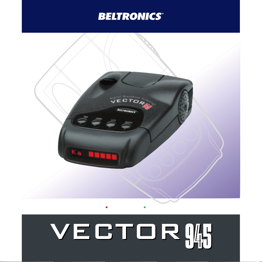
945
945945
Owner’s Manual
DIGITAL RADAR LASER SAFETY DETECTOR
Page 3

Congratulations
BEL V945 is an advanced radar/laser/safety
detector from BELTRONICS - the
technology leader. V945 includes X, K
and Super Wideband Ka radar detection,
front and rear laser detection and alerts to
the Safety Warning System. In addition,
V945 includes:
• 9 Digital Voice Messages (X, K, Ka,
Laser and 5 SWSTMCategory Messages)
• Customization of features depending
upon your area of travel.
• AutoScanTMmode intelligently reduces
unwanted false alarms, plus Highway
and two City settings.
• Ultra-bright text display for easy to read
information from any angle
If you’ve used a radar detector
before, the Quick Overview on pages 4
and 5, and the Programming information
on pages 12 and 13 will briefly explain all
features.
If this is your first detector, please
read the manual in detail to get the most
out of your V945’s outstanding
performance and innovative features.
Remember, a radar detector in not a
license to speed. Please drive safely.
FCC Note:
Modifications not expressly approved
by the manufacturer could void the
user’s FCC granted authority to
operate the equipment.
Page 4

Detachable Quick Reference Card
H Remove card along perforations H
VECTOR 945 Quick Reference Card
Out-of-the-box, V945 will operate as follows. However,
these features can be customized to your driving
preference (see reverse side for programming
instructions).
Operating VECTOR 945 using factory settings:
Operating Mode: Normal – V945 will engage a lengthy
power up test sequence when turned on and identify all
alerts with Text Message and Digital Voice.
Auto Mute: OFF – V945 will track the signal with a
continuous, full audio and visual alert.
Radar/Laser/SWSTMDigital Voice: ON – V945 will
present Digital Voice announcements of detected signals.
Safety Warning System®: ON – V945 will alert to
SWS™ signals if transmitters are operating.
Audio/Visual Scroll Rate: SLOW – all information in the
display will scroll slowly in the display for your
convenience.
Inverted Display Option: OFF – V945 will display all
H Remove card along perforations H
information “right reading” in the display.
Selectivity Mode: AutoScan™ - Reduces false signals.
Suitable for ALL driving environments.
Programming Details E
Page 5

Detachable Quick Reference Card
H Remove card along perforations H
VECTOR 945 Quick Reference Card
Operating Mode/Press and hold PWR button when unit is ON.
NORMAL *Standard, displays all information plus lengthy
MODS *Full power-up test sequence followed by Features
Q-START *No power up test sequence when turned on. Unit
To access Programmable Features, with the unit OFF, press and
hold the PWR and CITY button simultaneously.
Press the AUDIO button to select feature;
Press CITY button to move forward in the list;
Press DARK to move backward in the list;
Press PWR to save your selections.
AutoMute *When ON, unit will sound an alert only two or
Radar/Laser/SWS
Digital Voice *When ON, unit will sound Digital Voice alerts;
SWS™ *When ON, unit will alert to SWS™ signals.
Audio/Visual *Choose FAST or SLOW Scroll Rate.
Inverted *When ON, display can be read if unit is
Display mounted upside down.
Note: To re-set V945 to factory default, press and hold CITY
button until display shows: RESET
power up test sequence.
changed from factory pre-settings
displays only travel mode selected: A utoScan,
H i ghway, City X or Cit y ALL.
three times before engaging a clicking tone to
quietly monitor the signal. When OFF, unit will
sound continuous X/K/Ka alerts.
TM
when OFF, unit will sound unique audio tones
only.
providing SWS™ transmitting devices are in use.
H
H
Remove car
Remove car
d along per
d along per
forations
forations
H
H
2
Page 6

Table of Contents
Quick Overview 4-5
Installation 6-7
• Power Connection 6
• Mounting Location 6
• Windshield /Visor Mounting 7
Controls and Features 8-11
• Power up Test Sequence/
Operating Mode 8
• Tutorial Mode 9
• Set and Forget Memory 9
• Reset to Factory Settings 9
• Dark Button 9
• Audio Button 10
• AutoScanTM/Highway/City X/
City X/K/Ka 10-11
Programming 12-16
• Which Selectable Features
Can I Program? 12
• How to Program 12
• Selectable Features 13-14
Technical Details 15-21
• Specifications 15-16
• Interpreting Alerts 16-17
• How Radar Works 18
• How Laser Works 19
• How Safety Radar Works 20-21
Service 22-29
• Troubleshooting 22-24
• Service 26
• Registration 27
• Warranty and Accessories 29
3
Page 7

Quick Overview
To begin using your
VECTOR 945,
just follow these simple steps
1 Plug the angled end of the power
cord into the side jack of the
detector. Plug the opposite end into
the cigarette barrel; plug this portion
into your vehicles lighter socket.
2 Mount V945 on the windshield
using the supplied windshield
mount.
3 Press the PWR button, located top
left, to turn V945 on.
4 Press and hold the PWR button to
adjust the volume.
Please read the manual to fully understand
operations and features.
WINDSHIELD/VISOR MOUNT
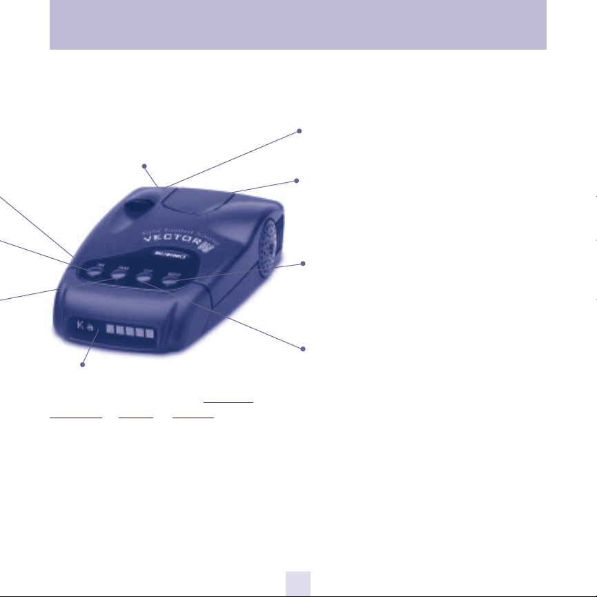
Remove cover on top of the detector to i
POWER JACK
Plug the Cord into this connector. Page 6
PWR BUTTON
Press the PWR button to turn
V945 on or off. Press and hold to select
operating mode. Page 8
DARK BUTTON
Press to adjust text display from full
bright to dim, plus Dark Mode.
In the Dark Mode, the power-on
indication will be changed to a dim “AD,”
“HD,” or “CD” (indicating AutoScanTM,
Dark, Highway Dark, or City Dark). In the
Dark Mode, V945’s meter will not
display during an alert, only the audio
will alert you. Page 9
4
Page 8
Quick Overview
RADAR ANTENNA AND LASER LENS
The rear lens of your V945 should have
a clear view of the road ahead. For best
performance, do not mount the V945
directly behind windshield wipers or
tinted areas. Page 6
ALPHANUMERIC TEXT DISPLAY
V945’s display will show Highway
AutoScan
power-on indication.
indicate radar band, and a precise bar
graph of signal strength. Page 24
will not light during an alert. Page 9
Radar Category messages. Page 24
TM
, City X
During an alert, the display will
Note: In the Dark Mode the display
The display will also show Safety
or City All as its
,
REAR LASER PORT
Receives laser signals from behind the
vehicle.
WINDSHIELD/VISOR MOUNT
Remove cover on top of the detector to
insert windshield or visor mount into this
slot. Page 7
AUTO MUTE/VOLUME CONTROL
Press and hold to adjust the volume level.
Briefly press this button (above the
display) to silence the audio for a specific
alert. Page 10
CITY BUTTON
Switches between AutoScanTM/Highway
City X, City X/K/Ka settings. In general,
we recommend AutoScanTM. Page 10
5
Page 9

Installation
POWER CONNECTION
To power V945, plug the elbow shaped
jack into the receptacle on the side of the
detector; the opposite end of the cord
connects to the cigarette barrel. Plug the
cigarette barrel into your vehicle’s
cigarette plug.
V945 operates on 12 volts DC negative
ground only. The lighter plug provided is
a standard size and will work in most
vehicles. Of course, your lighter socket
must be clean and properly connected
for proper operation.
Note: depending on your vehicle, the
lighter socket power may either be
continuously on, or it may be switched
on and off with your ignition switch.
In case your vehicle has continues power,
remember to remove power cord from
lighter socket when unit is not in use.
MOUNTING LOCATION
WARNING: BELTRONICS cannot
anticipate the many ways V945 can be
mounted.
It is important that you mount V945
where it will not impair your view nor
present a hazard in case of an accident.
Where to mount VECTOR 945
For optimum detection performance, we
recommend the following:
• Using the Windshield Mount, mount
your V945 level, and high enough on
your front windshield to provide a clear
view of the road from the front and
rear.
• Mount V945 away from windshield
wipers, other solid objects, and heavily
tinted areas that might obstruct the
radar antenna or laser lens.
6
Page 10
Installation
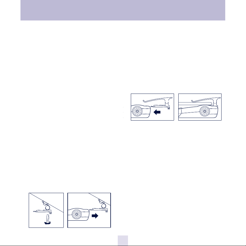
WINDSHIELD MOUNTING
1 Remove the mounting bracket cover
on top of the unit by pressing on the
raised dots and pushing outward. Store
the cover in a safe place.
2 Clean the selected windshield area,
position the suction-cup mount on the
windshield, and press firmly on each
suction cup to secure it in place.
3 Use a screw driver or a small coin to
adjust the angle of the suction-cup mount
until the base plate is level.
4 Slide detector onto base plate unit, it
snaps into place.
Note: Some vehicles (including some
Porsches) have a plastic coating on the
inside of the windshield designed to
protect occupants in case of an accident.
Use of the windshield bracket on this type
of windshield can permanently mark the
surface. Check with your dealer if you
are unsure whether your vehicle is
equipped with this type of windshield.
VISOR MOUNTING
1 Remove the mounting bracket cover
by pressing on the raised dots and
pushing outward. Store the cover in a
safe place.
2 Slide the visor clip onto the top of
the detector until is snaps into place.
Clip the detector to the edge of the sun
visor nearest the windshield.
7
Page 11

Controls and Features
POWER-UP TEST SEQUENCE/
START-UP MODE
Press the PWR button to turn the unit ON.
Depending upon the Operating Mode
selected, the power up test sequence and
confirmation of Radar/Laser/SWS™alerts
will be relayed to you as follows:
NORMAL (Factory Pre-Set Mode)
A lengthy, power up test sequence that
displays audio and text messages for
laser, Ka, K, X and Safety Warning
System®(SWS™) followed by the status
of the General Selectable Features each
time the unit is turned on. When
complete, unit is ready for operation
and will display Radar, Laser and SWS
messages when signals are detected.
Normal Mode is recommended when
first using your V945.
MODS (Modifications Mode)
Presents audio and text messages for
Laser, Ka, K, X and Safety Warning
System®(SWS™), followed by ONLY
those Selectable Features which have
been modified by the user from their
Factory pre-set state each time unit is
turned on. Unit is ready for operation
and will display Radar, Laser and SWS
messages when signals are detected.
Q-START (Quick-Start Mode)
Unit will bypass the power up test
sequence and will display the last
selected traveling mode:“
(factory default) “
X
” or “
Cit y
ALL”. Q-Start is
recommended when you are
comfortable with the detector and do
not require a rundown of sample
messages. Unit is ready for operation
and will display Radar, Laser and SWS
™
messages when signals are detected.
Whichever Operating mode you select,
V945 will be in standby mode and
ready to detect traffic Radar, Laser and
SWS™ signals. The display will show
Au t o S c a n
“
suitable for ALL driving conditions, unless
you change this to “
“
Cit y
” (factory pre-set which is
ALL” (see page 12).
H i g h w a y
Hig h w a y
Au t o S c a n™”
”, “
City
”, “
City X
™
™
” or
8
Page 12

Controls and Features
TUTORIAL MODE
The Tutorial Mode allows you to become
more familiar with all audible and visual
alerts. The message
the display followed by the audio and
corresponding Text Message for “LASER”,
“
Ka AUDIO”, “K AUDIO”, “X AUDIO”, sample
Radar alert and “SAFETY WARNING SYSTEM
SAMPLE ALERTS”. Three sample SWS
messages are then presented in the display
along with the corresponding Digital Voice
Messages.
You can access all five SWS™category
messages by pressing the AUDIO button.
“MSG 1” will appear in the display once
AUDIO is pressed. To move forward in the
list, press the CITY button; to move
backward in the list, press the DARK
button. Continue the steps above to play all
5 SWS™category messages.
To exit Tutorial Mode, press the PWR
button and your unit will be on and ready
to receive signals.
“
TUTORIAL”appears in
™
Set and Forget Memory
Any time your unit is turned off or
unplugged from the cigarette lighter socket,
all feature settings you have selected are
retained in the unit’s memory. Set and
Forget Memory eliminates the need to reset
your preferred feature settings each time
your unit is turned off and then back on.
Reset to Factory Settings
You can reset your unit to factory settings
for Start-Up mode, volume, DARK, AUDIO,
CITY and Selectable Features. To reset,
press and hold the CITY button until the
display shows “RESET“. Two “beeps“ will
sound and your unit will cycle through the
NORMAL Start-Up Mode.
DARK (Bright/Dim/Dark) Button
The DARK button allows selection of a
bright, fully adjustable dim or dark mode.
Your unit is factory preset to full bright
display. To engage dim mode, press and
hold the DARK button. The display will
cycle through various levels of dim
illumination. Release the button at your
chosen level. To engage dark mode, press
the DARK button a second time. A single
“beep” coupled with the brief illumination
of
“
DARK”on the display confirms your
selection.
9
Page 13

Controls and Features
“As”
You’ll notice an
(Highway mode), “Cx”(City mode) or “CA
(City ALL) remains dim to confirm your
unit is receiving power. To return to a full
bright setting, press the DARK button a
third time; two “beeps” confirm this
selection. Use of the DARK button does
not affect audio alerts.
Important—if you press the the DARK
button and do not receive audible
confirmation, the audio level has been set
too low.
AUDIO (Auto-Mute/V
Manual Muting of Audio Alerts
(Radar and SWS
Whether Auto-Mute is selected on or off in
Selectable Features, the audio alerts can be
completely muted by pressing the AUDIO
button during an alert. The display will
briefly show
be heard as long as the signal is present.
The unit will remain in manual mute mode
for approximately 12 seconds from the last
received alert.
Note—because Laser alerts are not
lengthy or sustained, muting is not
required (see page 21)
TM
“
(AutoScanTM), “H
olume Control) Button
)
QUIET”. No audible alert will
”
Volume Control
”
Press and hold the AUDIO button to
engage the volume control; the volume will
cycle high to low.
Release the AUDIO button when you
have reached your desired audio setting.
CITY (City/Highway) Button
The CITY button has four functions:
1. AutoScanTMMode
2. Highway Mode
3. City X Filtration Mode
4. City X/K/Ka Filtration Mode
AutoScanTMMode
V945 is factory shipped with AutoScan
engaged. AutoscanTMis designed to
automatically adjust sensitivity to X and K
Band Radar whatever your driving
environment. Whether driving in densely
populated urban areas or “wide open” rural
areas, AutoScanTMwill automatically reject
virtually all false signals which are shared
with traffic Radar on X and K Bands such as
door openers and security systems.
AutoScanTMis a “no-fuss” means of
achieving optimum signal selectivity.
TM
10
Page 14

Controls and Features
Highway
Select Highway mode when traveling in
rural or highway environments for
maximum X, K, Super Wideband Ka
sensitivity.
City X Mode
Select City X mode when traveling in
moderate city conditions of travel, and
some level of X band filtration is required.
Once engaged, weak X band signals
encountered will produce no audible alert
until the signal strength reaches a preset
level. However, visual alerts will be
processed the instant an X band signal is
detected, keeping you quietly informed.
Since most “false” X band signals are weak,
the use of the CITY mode allows you to
drive out of their range before they reach
the preset level and trigger a full audio
alert.
City All Mode (X, K, Super Wideband Ka)
This mode is ideal for use in areas where a
high level of microwave transmissions can
cause falsing on all three Radar bands. In
City All mode, your unit will provide an
initial short alert coupled with visual
confirmation of the band detected and
signal strength in the display. No further
audible alert is provided until the signal
strength reaches a preset level. When no
audio alert is provided, the visual alert
keeps you quietly informed.
11
Page 15

Programming
WHICH SELECTABLE FEATURES
CAN I PROGRAM?
The following features may be changed
depending upon your driving environment
and preference.
1. AutoMute ON or OFF
2. Radar/Laser/ SWS™ Digital Voice or Tone
3. Safety Warning System®ON/OFF
4. Audio/Visual Scroll Rate FAST or SLOW
5. Inverted Display Option ON/OFF
*Display references Radar and Laser only,
but does include SWS™voice as well.
How to program
1 With the unit OFF, press and hold the
PWR and CITY buttons simultaneously.
The word “FEATURES” will appear in the
display, followed by the status of the first
Selectable Feature.
2 Press the AUDIO button to make your
selection.
3 Press the CITY button to move to the
next Selectable Feature. To move backward
in the list, press the DARK button.
4 Press the PWR button to exit
Selectable Features mode. To confirm your
unit is ready for operation, and what mode
of travel your unit is operating, the display
will read: “AutoS can”, “H i ghway”,
“Cit y X ” or “Ci ty ALL”.
12
Page 16

Programming
Feature 1 – AutoMute On or Off
With “Am u t e o n ”, your unit will
provide several X, K or Super
Wideband Ka audio alerts followed by
the Digital Voice announcement of the
signal detected. After the Digital Voice
announcement, a “clicking” tone keeps
you quietly informed for as long as the
signal is present. This clicking becomes
more rapid as the strength of the Radar
signal increases. “Am u t e o n ” enables
you to conveniently monitor extended
encounters without having to manually
mute or adjust the volume setting.
With “A mut e o f f ”, your unit will
provide a continuous series of X, K,
Super Wideband Ka audio alerts and
Digital Voice announcements of the
signal detected. Digital Voice prompts
are provided once after the initial audio
alert. This standard setting is often
preferred when background noise in a
vehicle is loud. Factory setting is
“Am u t e o f f ”.
Note: because of its urgency, Laser alerts
are not affected by this mode.
Feature 2 – Radar/Laser/SWS™ Digital
Voice Prompts
With “Vo i c e o n ”, unit will provide
Digital Voice prompts followed by
“beeps” when X/K/Ka and Laser
signals are detected. With “Vo i c e o f f”,
unit will sound unique audio tones
only. Factory setting is “Vo i c e o n ”.
Feature 3 – Safety Warning System
®
(SWS™)
With “SWSo n ”, unit will provide a
message when signals from SWS
transmitters are detected. Factory
setting is “SWSo n ”.
™
Feature 4 – Audio/Visual Scroll Rate
When “SCRs l o w ” is selected, unit will
provide a slow cycling of audio/visual
messages. When “SCR fa s t ” is
selected, unit will provide a fast cycling
of audio/visual messages. Factory
setting is “
SCRs l o w
”.
13
Page 17

Programming
Feature 5 – Inverted Display Feature
When selected, your unit can be
mounted to the visor using the hook &
loop fastener upside down and the
display will remain right reading.
“Upside down” mounting may allow
for easier access to the unit’s functions.
Note: Inverted display is ON when the
check mark symbol is FLASHING; inverted
display is OFF when the underscore line is
flashing.
14
Page 18

FEATURES AND SPECIFICATIONS
Technical Details
Operating Bands
• X-band 10.525 GHz ± 25 MHz
• K-band 24.150 GHz ± 100 MHz
• Ka-band 34.700 GHz ± 1300 MHz
• Laser 904nm
Radar Receiver/Detector Type
• Superheterodyne, GaAs FET VCO
• Scanning Frequency Discriminator
• Digital Signal Processing (DSP)
Laser Detection
• Quantum Limited Video Receiver
• Multiple Laser Sensing Diodes
Power Requirement
• 12VDC, Negative Ground
Sensitivity Control
• Highway, AutoScanTM, City X and
City X/K/Ka
Auto Calibration Circuitry
Shadow Technology®II for
undetectability to Technosonic VG-2.
Dimensions (Inches)
• 1.8” H x 3.1” W x 5.3” L
Patented Technology
V945 is covered by one or more of the
following US patents.
6,587,068 6,400,305 6,249,218 6,069,580
5,668,554 5,600,132 5,587,916 5,559,508
5,365,055 5,347,120 5,446,923 5,402,087
5,305,007 5,206,500 5,164,729 5,134,406
5,111,207 5,079,553 5,049,885 5,049,884
4,961,074 4,954,828 4,952,937 4,952,936
4,939,521 4,896,855 4,887,753 4,862,175
4,750,215 4,686,499 4,631,542 4,630,054
4,625,210 4,613,989 4,604,529 4,583,057
4,581,769 4,571,593 4,313,216 D314,178
D313,365 D310,167 D308,837 D296,771
D288,418 D253,752
V945 is also covered by one or more of
the following Canadian patents:
1,295,715 1,295,714 1,187,602 1,187,586
Other patents pending. Additional patents
may be listed inside the product.
15
Page 19

Technical Details
INTERPRETING ALERTS
Although the V945 is a comprehensive
warning system and this handbook is as
complete as we can make it, only
experience will teach you what to expect
from your V945 and how to interpret
what it tells you. The specific type of radar
being used, the type of transmission
(continuous or instant-on) and the location
of the radar source affect the radar alerts
you receive.
The following examples will give you
an introduction to understanding the
V945’s warning system for radar, laser and
safety alerts.
ALERT
The V945 begins to sound slowly, then
the rate of alert increases until the alert
becomes a solid tone. The Signal Meter
ramps accordingly.
V945 emits short alerts for a few seconds
and then falls silent only to briefly alert and
fall silent again.
V945 suddenly sounds a continuous tone
for the appropriate band received. All
segments in the Signal Strength Meter are lit.
A brief laser alert.
EXPLANATION
You are approaching a continuous radar
source aimed in your direction.
An instant-on radar source is being used
ahead of you and out of your view.
An instant-on radar source or laser source is
being used nearby. This kind of alert
requires immediate attention!
Laser is being used in the area. Because laser
is inherently difficult to detect, any laser
alert may indicate a source very close by.
16
Page 20

Technical Details
ALERT
V945 receives weak signals. These signals
may be a little stronger as you pass large,
roadside objects. The signals increase in
frequency.
V945 alerts slowly for awhile and then
abruptly jumps to a strong alert.
V945 alerts intermittently. Rate and
strength of alerts may be consistent or vary
wildly.
V945 alerts intermittently. Rate and
strength of signal increases with each alert.
V945 gives an X-band, or K-band alert
intermittently.
EXPLANATION
A moving patrol car with continuous radar is
overtaking you from behind. Because these
signals are reflected (reflections are
increased by large objects), they may or may
not eventually melt into a solid point even
when the patrol car is directly behind you.
You are approaching a radar unit concealed
by a hill or an obstructed curve.
A patrol car is traveling in front of you with a
radar source aimed forward. Because signals
are sometimes reflected off of large objects
and sometimes not, the alerts may seem
inconsistent.
A patrol car is approaching from the other
direction, sampling traffic with instant-on
radar. Such alerts should be taken seriously.
You are driving through an area populated
with radar motion sensors (door openers,
burglar alarms, etc.). Since these transmitters
are usually contained inside buildings or
aimed toward OR away from you, they are
typically not as strong or lasting as a real
radar encounter.
CAUTION: Since the characteristics of these alerts may be similar to some of the preceding examples,
overconfidence in an unfamiliar area can be dangerous. Likewise, if an alert in a commonly traveled
area is suddenly stronger or on a different band than usual, speed radar may be set up nearby.
17
Page 21

Technical Details
HOW RADAR WORKS
Traffic radar, which consists of microwaves,
travels in straight lines and is easily reflected
by objects such as cars, trucks, even
guardrails and overpasses. Radar works by
directing its microwave beam down the
road. As your vehicle travels into range, the
microwave beam bounces off your car, and
the radar antenna looks for the reflections.
Using the Doppler Principle, the radar
equipment then calculates your speed by
comparing the frequency of the reflection
of your car to the original frequency of the
beam sent out.
Traffic radar has limitations, the most
significant of these being that it typically can
monitor only one target at a time. If there is
more than one vehicle within range, it is up
to the radar operator to decide which target
is producing the strongest reflection. Since
the strength of the reflection is affected by
both the size of the vehicle and its
proximity to the antenna, it is difficult for
the radar operator to determine if the signal
is from a sports car nearby or a semi-truck
several hundred feet away.
Radar range also depends on the power
of the radar equipment itself. The strength
of the radar unit’s beam diminishes with
distance. The farther the radar has to travel,
the less energy it has for speed detection.
Because intrusion alarms and motion
sensors often operate on the same
frequency as X-Band radar, your V945 will
occasionally receive non-police radar
signals. Since these X-Band transmitters are
usually contained inside of a building, or
aimed toward the ground, they will
generally produce much weaker readings
than will a true radar encounter.
As you become familiar with the sources of
these pseudo alarms in your daily driving,
they will serve as confirmation that your
V945’s radar detection abilities are fully
operational.
18
Page 22

Technical Details
HOW LASER (LIDAR) WORKS
Laser speed detection is actually LIDAR
(Light Detection and Ranging). LIDAR guns
project a beam of invisible infrared light.
The signal is a series of very short infrared
light energy pulses, which move, in a
straight line, reflecting off your car and
returning to the gun. LIDAR uses these light
pulses to measure the distance to a vehicle.
Speed is then calculated by measuring how
quickly these pulses are reflected given the
known speed of light.
LIDAR (or laser) is a newer technology
and is not as widespread as conventional
radar, therefore, you may not encounter
laser on a daily basis. And unlike radar
detection, laser detection is not prone to
false alarms. Because LIDAR transmits a
much narrower beam than does radar, it is
much more accurate in its ability to
distinguish between targets and is also more
difficult to detect. AS A RESULT, EVEN
THE BRIEFEST LASER ALERT SHOULD
BE TAKEN SERIOUSLY.
There are limitations to LIDAR
equipment. LIDAR is much more sensitive
to weather conditions than RADAR, and a
LIDAR gun’s range will be decreased by
anything affecting visibility such as rain, fog,
or smoke. A LIDAR gun cannot operate
through glass and it must be stationary in
order to get an accurate reading. Because
LIDAR must have a clear line of sight and is
subject to cosine error (an inaccuracy,
which increases as the angle between the
gun and the vehicle, increases) police
typically use LIDAR equipment parallel to
the road or from an overpass. LIDAR can be
used day or night.
19
Page 23

Technical Details
HOW SAFETY RADAR WORKS
Safety Warning System®, or SWS™, uses a
modified K-band radar signal. The SWS™
safety radar system is comprised of five
categories. The SWS™ message categories
are listed on the facing page.
From the factory, your V945 is
programmed with SWS™ decoding ON. If
SWS™ is used in your area, your V945
will display the safety message categories
associated with the signal.
Since Safety radar technology is
relatively new, and the number of
transmitters in operation is not yet
widespread, you will not receive Safety
signals on a daily basis. Do not be surprised
if you encounter emergency vehicles, road
hazards and railroad crossings that are
unequipped with these transmitters. As
Safety transmitters become more prevalent
(the number of operating transmitters is
growing every day), these Safety radar
signals will become more common.
20
Page 24

Technical Details
List of Safety Warning System
®
SWSTMAlerts
CATEGORY 1
Highway Construction of Maintenance
“Highway Work”
CATEGORY 2
Highway Hazard Zone Advisory
“HazardZone”
CATEGORY 3
Weather Related Hazards
“Weather”
CATEGORY 4
Travel Information/Convenience
“TravelInfo”
CATEGORY 5
Fast/Slow Moving Vehicles
“Moving”
Note: “MessageUnknown” confirms
incomplete or unknown messages.
21
Page 25

Troubleshooting
PROBLEM
V945 beeps briefly at the same
location every day, but no radar
source is in sight.
V945 does not seem sensitive
to radar or laser.
V945 did not alert when a
police car was in view.
V945 did not provide a Safety
signal while within range of an
emergency vehicle.
V945’s display is not working.
V945’s audible alerts are less
loud after the first few alerts.
SOLUTION
• An X-band motion sensor or intrusion alarm is located
within range of your route. With time, you will learn
predictable patterns of these signals.
• Make sure that windshield wipers do not block
V945’s radar antenna and that the laser lens is not
behind tinted areas.
• Determine if your vehicle has an Instaclear®,
ElectriClear®or solar reflective windshield which may
deflect radar or laser signals.
• V945 may be in City All Mode.
• VASCAR (Visual Average Speed Computer and
Recorder) a stopwatch method of speed detection,
may be in use.
• Officer may not have radar or laser unit turned on.
• Safety transmitters may not be commonly used in
your area.
• Press the DARK button to return to full Bright Mode.
• V945 is in AutoMute Mode. See page 8 for details.
22
Page 26

Troubleshooting
PROBLEM
V945 bounces or sags on
windshield.
V945’s power-on sequence
reoccurs while you are driving.
Your 14-year old son has
changed all 7 of the
Programming options.
V945 will not turn on.
V945 feels very warm.
SOLUTION
• V945 is not making contact with the windshield to
provide stability. While holding down V945’s
QuickMount button, slide V945 toward the
windshield so that the back top edge makes firm
contact.
• A loose power connection or dirty lighter socket can
cause V945 to be briefly disconnected.
• You can return all of the programming options to the
factory defaults by pressing and holding down the
CITY button.
• Check that the power is ON.
• Check that vehicle ignition is ON.
• Check that vehicle lighter socket is functional.
• Try V945 in another vehicle.
• It is normal for V945 to feel warm.
23
Page 27

Explanation of Displays
As Sensitivity control is in AutoScan, display is in Dark mode (page 9)
H Sensitivity control is in Highway mode, display is in Dark mode (page 9)
Cx Sensitivity control is in City X mode, display is in Dark mode (page 9)
HwyWork One of five Safety Warning System
TM
Category Messages (pages 21)
Caution V945 has detected a Safety Radar Signal, but the signal isn’t yet strong
enough to decode the specific safety message (page 20)
NNNNN
Ka
NNNNN
K
NNNNN
X
Note: There are 5 signal strength bars, depending upon the strength of the signal detected,
1, 2, 3, 4, or all 5 will illuminate.
V945 has detected a full strength Ka Band signal
V945 has detected a full strength K Band signal
V945 has detected a full strength X Band signal
24
Page 28

25
Page 29

Service
SERVICE PROCEDURE
If your V945 ever needs service, please
follow these simple steps:
1 Check the troubleshooting section of
this manual. It may have a solution to your
problem.
2 Call us at 1-800-341-2288. We may be
able to solve your problem over the phone.
If the problem requires that you send your
V945 to the factory for repair, we will
provide you with a Service Order Number,
which must be included on the outside of
your shipping box.
Enclose the following information with your
V945:
• Your Service Order Number
• Your name and return address
• Your daytime telephone number
• A description of the problem you are
experiencing.
OUT OF WARRANTY REPAIRS
For out of warranty repairs, include
prepayment in the amount you were
quoted by the Beltronics Customer Service
Representative. If the detector has been
damaged, abused or modified, the repair
cost will be calculated on a parts and labor
basis. If it exceeds the basic repair charge,
you will be contacted with a quotation. If
the additional payment is not received
within 30 days (or if you notify us that you
choose not to have your V945 repaired at
the price quoted), your V945 will be
returned, without repair. Payment can be
made by check, money order, or credit
card.
Ship complete V945 to:
BELTRONICS
Customer Service Department
Service Order Number ______________
5442 West Chester Road
West Chester, Ohio 45069
For your own protection, we recommend
that you ship your V945 postpaid and
insured. Insist on a proof of delivery, and
keep the receipt until the return of your
V945.
26
Page 30
Register
online:
@
www.
beltronics
.com
PRODUCT REGISTRATION CARD
27
or register online at our web address: www.beltronics.com.
H Remove card along perforations H H
E If you purchased your detector directly from BELTRONICS, you do not need to fill this out.
E If you did not purchase your detector directly from BELTRONICS, please fill out this section and return to us,
Address______________________________________________________________________
1. First Name:___________________ Middle Initial____ Last Name__________________________
Phone Number (In case we have a question)_____________________________________________
City_______________________________________ State_____________ ZIP______________
____________________________________________________________________________
____________________________________________________________________________
2. Product Purchased________________________ Model___________ Serial Number___________
3. Place of Purchase__________________________________ Date_________ Price____________
4. Primary reason for purchasing this BELTRONICS product____________________________________
Page 31

BELTRONICS INC
5442 WEST CHESTER RD
WEST CHESTER OH 45069-9789
ATTN CUSTOMER SERVICE
H Remove card along perforations H
28
Page 32

Warranty and Accessories
BELTRONICS One Year
Limited Warranty
BELTRONICS warrants your
V945 against all defects in materials and
workmanship for a period of one (1) year
from the date of the original purchase,
subject to the following terms and
conditions:
The sole responsibility of BELTRONICS
under this Warranty is limited to either
repair or, at the option of BELTRONICS,
replacement of the V945 detector. There
are no expressed or implied warranties,
including those of fitness for a particular
purpose or merchantability, which extend
beyond the face hereof. Some states do not
allow limitations on how long an implied
warranty lasts, so the above limitations may
not apply to you.
BELTRONICS is not liable for any
incidental or consequential damages arising
from the use, misuse, or mounting of the
V945. Some states do not allow the
exclusion or limitation of incidental or
consequential damages, so the above
limitation or exclusion may not apply to you.
This Warranty gives you specific rights.
You may have other legal rights which vary
from state to state. This Warranty does not
apply if the serial number on the housing of
the V945 has been removed, or if your
V945 has been subjected to physical
abuse, improper installation, or
modification.
ACCESSORIES
See all of our products and accessories at
www.beltronics.com
29
 Loading...