

Beltronics 906 Owner's Manual
bodership fhrough lrmodon and Techrdogy @
To ensure maximum benefit from your unit, please read the
entire manual before operating your detector.
Remember, owning a radar detector does not give you a
license to speed. Alerts from a Radar detector serve as an
effective reminder to check your speed. Laws vary
throughout North America governing the use of a Radar
detector. It is your responsibility to follow these laws.
ro
of Features
1.
2.
3.
4.
5.
6.
7
8.
9.
10
11
12
13
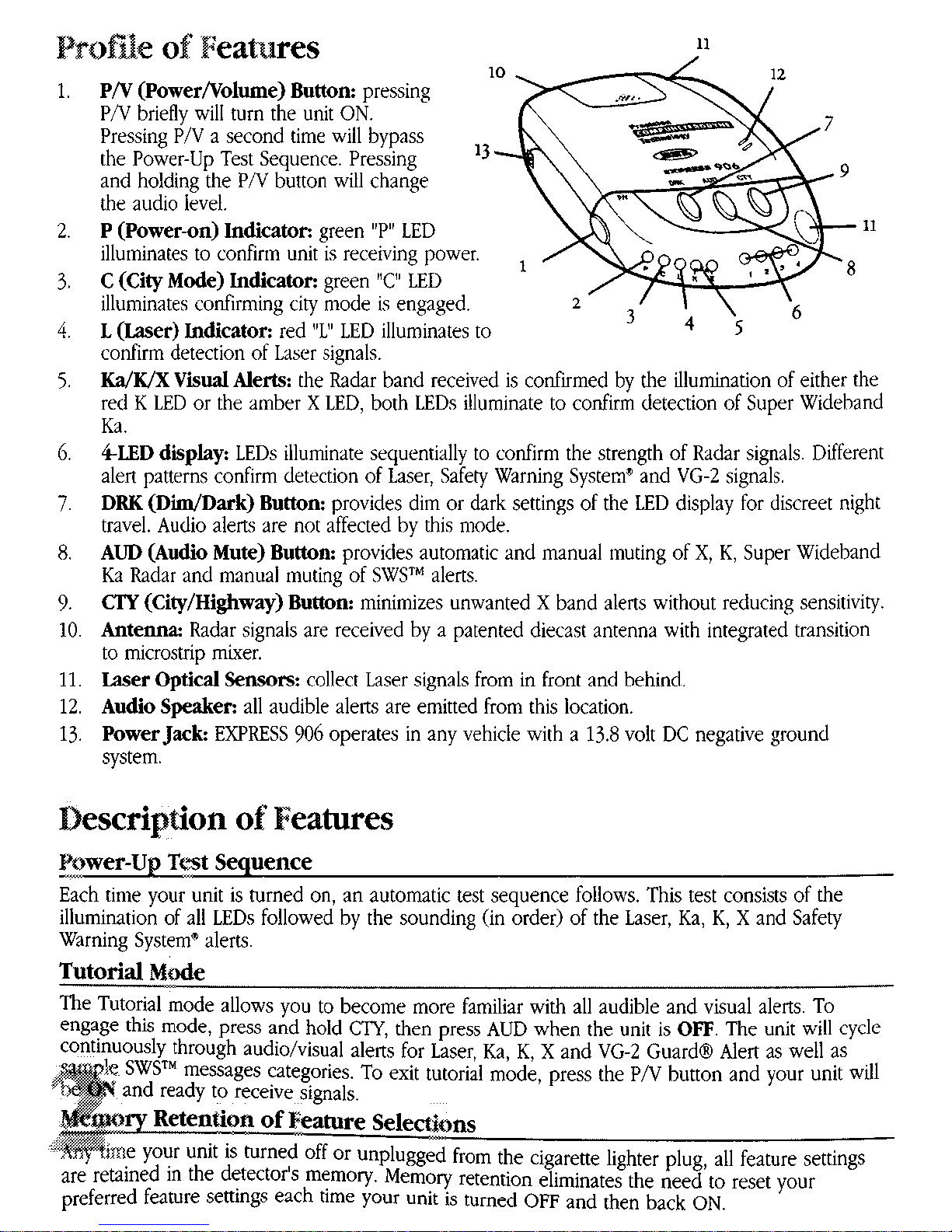
PiV (Power/Volutne) Button:
pressing
PN briefly will turn the unit ON.
Pressing P/V a second time will bypass
the Power-Up Test Sequence. Pressing
t3-
and holding the P/V button will change
the audio level.
P (Power-on) Indicator: green “P” LED
illuminates to confirm unit is receiving power
C
(City Mode) Indicator: green “C”
LED
illummates confirming city mode IS engaged.
L (Laser) Indicator: red “L” LED illuminates to
confirm detection of Laber sienals.
Ka/K!X
Visual
Alerts: the &ar band received is confirmed by the illumination of either the
red K LED or the amber X LED. both LEDs illummate to confirm detection of Suoer Wideband
Ea.
&ED
display:
LEDs illuminate sequentially to confirm the strength of Radar signals Different
alert patterns confirm detection of Laser, Safety Warning System” and VG-2 signals.
DRK
(DiiDark) Buttom
provides dim or dark settings of the LED display for discreet night
travel. Audio alem are not affected by this mode.
AUD (Audio Mute) Button:
provides automatic and manual muting of X, K, Super Wideband
Ka Radar and manual muting of SWSTM alerts.
CTY (City/Highway)
Button:
minimizes unwanted X band alerts without reducing senswity.
Antenna Radar signals are received by a patented diecast antenna with Integrated transition
to mlcrostrip mixer.
Laser Optical Sensorsz collect Laser signals from in front and behind.
Audio Speaker:
all audible alerts are emitted from this location.
Power Jack:
EXPRESS 906 operates in any vehicle with a 13.8 volt DC negative ground
system.
Each tmte your unit is turned on, an automatic test sequence follows. This test consists of the
illumination of all LEDs followed by the sounding (in order) of the Laser, Ka, K, X and Safety
Warning Systemm alerts
Tutorial Mode
‘Ihe Tutorial mode allows you to become more familiar with all audible and visual alens To
engage thii mode, press and hold CTY, then press AUD when the unit is OFF The unit will cycle
continuously through audio/visual alerts for Laser, Ka, K, X and VG-2 Guard@ Alert as well as
ies. To exit tutorial mode, press the PN button and your unit wll
Adjwting the Audio Level
Once your umt has completed the self-test, the audio level can be adjusted by pressing and
holding the P/V button. As you hear the audio level change, the 4.LED display provides a visual
reference of the audio level. To reverse the drection in which the audio cycles, bnefly release,
then hold down the P/V button again.
DRK (Dim/Dark) Button
Press the DRK button once to engage the “dim” mode of the LED display. Press the DRK button
again to completely cancel illumination of the LED display; the green “P” LED wll remain in “dim”
mode to confirm your unit ib receiving power. Press DRK a third time to return the display ro full
bright.
Note: ifyoupress the DRK button and do not receive audible
confiwnation,
the audio level bus
been set too low.
AUD (Audio Mute) Buttp (Radar and SWS”)
-“.
The ALJD button provides three settings:
Continuous Audio, Automatic Mute
and
Manual Mute.
Continuous Audio:
Your unit has been preset at the factory to provide continuous XIWKa audio
alerts. This standard setting is often preferred when background noise in a vehicle is loud.
Automatic Mute
Press the AUD button once when the unit is recewing NO alerts to engage
Automatic Mute mode. The alert pattern when this mode is activated consists of several X/K or Ka
alerts followed by a “clicking” tone which will momtor the duration of the slgnal encounter. As the
signal increases m mrens~ty, the “clicking” tone will become mire rapid. Automatic Mute mode
enables you to conveniently monitor extended encounters without having to manually mute or
adjust the volume setting. To return to the audio alert mode, press the AUD button a second time
(while the unit is not alerting).
Manual Mute
Regardless of the AUD mode selected (continuous or Automatic), the audio alerts
can be completely muted by pressing the AUD button during an alert. Once the alert has passed,
the unit will revert to the previous AUD setting (continuous or automatic mute)
CTY (City/Highway) Button
The CTY button is designed to reduce the number of alerts received from unwanted s~wces such
as door alarms, intrusion alarms and other devices which share X band wth pohce radar. Signals
from non-police Radar sources are frequently encountered in urban and suburban areas, making
use of this mode ideal in these areas.
Press CTY once to engage the city mode. With CT?’ engaged, no audible alert will be heard until
nal strength reaches a preset level. Visual alerts, however, will be processed the instant an X
~gnal is detected, keeping you quietly informed.
‘ng CTY mode will not change K or Super Wideband Ka alert patterns. Detection of even
,,,
rhe weakest K or Super Wtdeband Ka signals will result m Immediate audio and visual alerts. In
addition, reception of Instant-On X band Radar produces the speclal Instant-On alert
NOTE:
CTY
mode
has no
e?ect
on the reception of
Laser signals
: Safety Warnmg System” (factory shipped
ON) and VG-2 Guard@ Alert (factory shipped OFF)
When activated, Safety Warning System” will
detect signals from SW?? transmittas and alert you to potential road hazards m five different
categories (see enclosed SWSTM insert). VG-2 Guard Alert”, when activated, will detect signals from
the Interceptor VG-2 Radar Detector Detector; factory setting is OFF.
Note
on& engage VG-2
Guard Alelf in areas known to use the Interceptor VG-2 Radar Detector Detector
Esltering Selectabk Feahxes MO&
“. --.
1. With the unit OFF, press the CTY and P/V buttons simultaneously.
2. A “beep” will be heard, coupled wth the illumination of the amber “X” LED.
3. The first LED in the signal strength display confirms the status of the SWSTM feature. If the LED
is solid, SWSTM feature is ON, but may be turned OFF by pressing the AUD button.
4. Press the CT?’ button to go to VG-2 Guard” Alert feature.
5 The second red LED in the signal strength &play confirms the status of VG-2 Guard” Alert
If the LED is solid, the feature is ON, but may be turned OFF by pressing the AUD button.
6. Press the P/v button to exit Selectable Features mode. Two “beeps” confirm you have exited
Selectable Features and your unit will be operational, based on your selections made.
es
Do not mount your unit directly behind wmdsh~eld wipers or mirrored sunscreens which block
Radar and Laser signals and substantially reduce warning range. Unlike “after market” mirrored
sunscreens,
regular tinted glass does not affect Radar reception. Radar signals are also reflected by
the “heated windshield” known as InstacleaF and Electricleaig available as an option on some
vehicles, making any detector ineffective If in doubt, check with an appropriate dealership to see
if this applies to your vehicle.
TO achieve optimum performance, regardless of which mounting position you choose, follow these
basic steps:
I. Consider occupant safety when selecting a mounting location. Choose a location where the
it will not be hazardous in case of an accident.
r optimum detection, position your unit with a
clear,
unobstructed view of the road from
front and rear.

3. Do not allow the unit to make contact with the windshield This will eliminate unnecessary
vibration.
4. AvoId placmg your unit in direct sunlight. During the summer, interior temperatures of an
enclosed vehicle can sometimes reach temperaturea that will cause premature aging of the
unit.
5. Your detector IS not waterproof; exposure to water may cause damage
Dash Mouna&
1. Select an area that is relatwely level, clean and dry Adhere the soft portion of the enclosed
hook and loop fastener to this area and the correspondmg hard portion to the bottom of
your unit
2. Fasten unit to dash by placing hook and loop prces together
Visor Mounting
1. Remove the detector’s cover by pressing on the raised dots and pushmg outward. Store the
COW3
2 Slide the visor clip onto the top of the detector until it snaps into place. Clip the detector to
the edge of the sun wsor nearest the windshield
Windshield Mounting
1. Remove the detector’s cover by pressq on the raised dots and pushing outward.
2. Clean the selected windshield area, position the suction-cup mount on the windshield and
press Firmly on each suction cup to secwe it m place.
3.
Use a screw driver or small coin to adjust the suction-cup mount until the base plate is level.
:” I ;:,
 Loading...