


Nr. Documento
Revisione
Autore
Data stampa
Nr. pagine
M_S2014
01
32

PAG. 2/32
Contents
Contents ..................................................................................................... 2
Important Notice ........................................................................................ 3
1. SAFETY INSTRUCTIONS ...................................................................... 4
1.1 General .....................................................................................................4
1.2 Safety Instructions .....................................................................................5
2. DEVICE DESCRIPTION ........................................................................ 6
2.1 Introduction ..............................................................................................6
2.2 Area of application .....................................................................................7
2.3 Hardware ..................................................................................................8
2.3.1 Control elements and interfaces .......................................................... 8
2.3.2 Device connections: power and high voltage ....................................... 10
2.3.3 Device connections: control signals and interfaces ............................... 11
2.4 Software ................................................................................................. 13
2.4.1 Operating modes ............................................................................. 13
3. Description of the functionality ......................................................... 14
3.1 Soft Start ................................................................................................ 14
3.2 Droop Compensation ................................................................................ 14
3.3 ‘Keep alive’.............................................................................................. 15
3.4 Limiters .................................................................................................. 16
3.4.1 V/f Limiter ...................................................................................... 16
3.4.2 Minimum excitation current............................................................... 16
3.4.3 Maximum excitation current .............................................................. 17
3.4.4 Minimum capability .......................................................................... 17
3.4.5 Massima capability ........................................................................... 18
4. References and Regulations .............................................................. 19
4.1 Field Current Regulation (FCR) ................................................................... 20
4.2 Automatic voltage regulator (AVR) ............................................................. 20
4.3 Automatic Power Factor regulation (PF) ...................................................... 21
4.4 Automatic reactive power regulation (VAR) ................................................. 21
4.5 Digital reference adjust by calibrator (U/Down)............................................ 22
4.6 Digital reference adjust by analog (Pot/An. In) ............................................ 22
5. OPERATOR INTERFACE ..................................................................... 23
5.1 Control keypad and display ....................................................................... 23
5.2 Navigating the menus ............................................................................... 24
5.3 Parameters saving .................................................................................... 25
5.3.1 Menu d – Display ............................................................................. 26
5.3.2 Menu r – References and Regulators .................................................. 26
5.3.3 Menu I – Inputs and outputs ............................................................. 27
5.3.4 Menu P – Parameters ....................................................................... 27
5.3.5 Menù C........................................................................................... 28
6. MAINTENANCE AND FAULTS ............................................................. 29
6.1 Safety regulations .................................................................................... 29
6.2 Maintenance ............................................................................................ 29
6.3 Trouble shooting ...................................................................................... 29
6.4 Repair..................................................................................................... 30
7. General Data ..................................................................................... 31

PAG. 3/32
Important Notice
Our experience has shown that, if the information and recommendations contained in
this Operating Instructions are observed, the best possible reliability of our products is
assured.
The data contained herein purports solely to describe the product and it is not a
warranty of performance or characteristics. It is with the best interests of our
customers in mind that we constantly strive to improve our products and keep them
abreast of advances in technology. This may, however, lead to discrepancies between
a product and its "Technical Description" or "Operating Instructions".
This document has been carefully prepared and reviewed, however should in spite of
this the reader find an error, he is requested to inform us at his earliest convenience.
It is scarcely possible for the operating instructions for technical equipment to cover
every eventuality, which can occur in practice. We would therefore request you to
notify us or our agent in the case of all unusual behavior that does not appear to be
covered by these operating instructions.
It is pointed out that all local regulations must be observed when connecting and
commissioning this equipment in addition to these operating instructions.
We cannot accept any responsibility for damage incurred as a result of mishandling
the equipment regardless of whether particular reference is made in these operating
instructions or not.
We lay particular stress on the fact that only genuine spare parts should be used for
replacements.
All rights with respect to this document, including applications for patent and
registration of other industrial property rights, are reserved. Unauthorized use, in
particular reproduction or making available to third parties, is prohibited.

PAG. 4/32
1. SAFETY INSTRUCTIONS
1.1 General
The safety instructions shall be followed during installation, commissioning, operation and
maintenance of the excitation system. Read all instructions carefully before operating the
device and keep this manual for future reference.
Required Qualification
Personnel involved in installation work and commissioning of the S2014 must be familiar,
specially instructed and informed about the residual danger areas according to the regulations
currently in force.
Operating personnel is not permitted to work at the control system.
Specially instructed personnel must only carry out maintenance and repair work.
The maintenance personnel must be informed about the emergency shutdown measures and
must be capable of turning off the system in case of emergency.
The maintenance personnel must be familiar with the accident prevention measures at their
workplace and must be instructed in first aid and fire fighting.
It is the owner’s responsibility to ensure that each person involved in the installation and
commissioning of the S2014 has received the appropriate training or instructions and has
thoroughly read and clearly understood the safety instructions in this chapter.

PAG. 5/32
1.2 Safety Instructions
The safety instructions always appear at the beginning of each chapter and/or precede
any instruction in the context where a potentially dangerous situation may appear.
The safety instructions are divided into five categories and emphasized by the use of
the following layout and safety signs:
DANGER!
This symbol indicates an imminent danger resulting from
mechanical forces or high voltage. A non-observance leads to
life-threatening physical injury or death.
WARNING!
This symbol indicates a dangerous situation. A non-observance
may lead to bad or life-threatening physical injury or death.
CAUTION!
This symbol indicates a dangerous situation. A non-observance
may lead to physical injury or cause damage to the converter.
NOTICE!
This symbol emphasizes important information. A nonobservance may cause damage to the converter or to objects
close to it.
IMPORTANT!
This symbol indicates useful information. Not to be used to
indicate dangerous situations.

PAG. 6/32
2. DEVICE DESCRIPTION
2.1 Introduction
S2014 is an automatic voltage regulator of the latest design for controls alternators
excitation. The unit contains the most advanced microprocessor technology together
with SCR semiconductor technology (Silicon Controlled Rectifier).
A practical and simple-to-operate panel on the unit is used for all control operations.
In addition, user friendly software facilitates commissioning allows optimization of
operation.
The mechanical construction is compact and robust.

PAG. 7/32
2.2 Area of application
This advanced-design automatic voltage regulator is used for the excitation of
synchronous machines. This unit is only suitable for this one area of application.
The regulator can also be switched over to function as a automatic voltage regulator,
power factor or reactive power regulation.
SM= Synchronous Machine
E = Exciter
PMG = Permanent-Magnet-Generator
Generator excitation from generator
output
Generator excitation with
PMG or external supply.
Replacement of voltage regulators for
generators with direct-current
excitation machines.
PAG. 8/32
2.3 Hardware
Structure:
The device is built into a plastic casing, depending on the nominal output current some
models have an aluminum base for cooling.
The connection terminals are integrated on top of the circuit boards.
Power electronics:
The power part is fitted with SCR semiconductors.
The average value of the output voltage is always positive. The output is protected
against short-circuit by a fuse.
Control elements:
The operating keys and the display are located on the circuit board.
The connector of the communication port it is located on the regulator.
Installation:
The site of installation must be dry and free of dust.
Mounting:
The regulator must be installed inside the machine or inside the control panel in order
to be protected against accidental contacts. For fastening the regulator, 4 MA throughscrews should be tightened with self-locking nuts in two corners holes.
It is recommended to bind the regulator back on a metal plate for better dissipation.
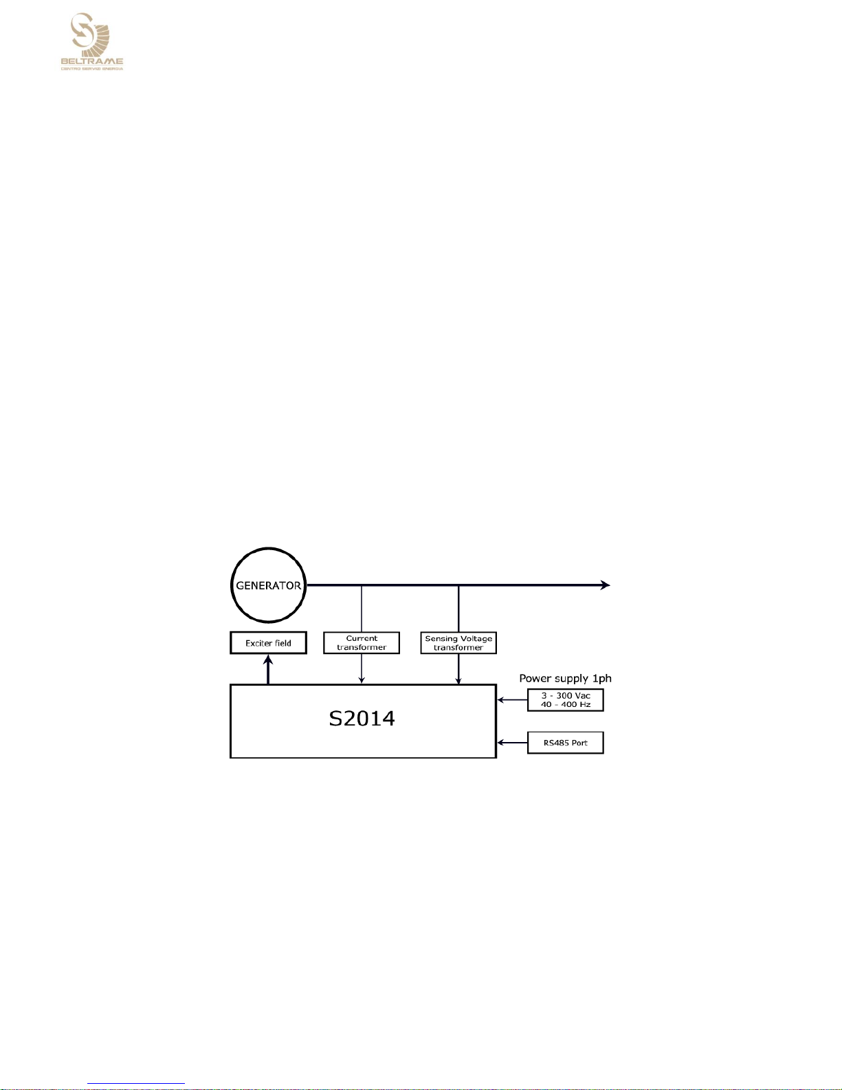
Connection diagram:
2.3.1 Control elements and interfaces
Carrying out settings on the unit
The displays and the four keys are sufficient to allow complete operation.
All settings can be carried out directly on the unit without additional equipment.
Configuration of inputs and outputs;
Parameter setting;
Display of important measuring values.

PAG. 9/32
Interface with PC
Parameter setting and also optimization is possible using the user-friendly software
S2014 Config for Microsoft Windows.
Connection cable with RS-485 Half-Duplex (two wire)
Configuration of inputs and outputs;
Parameter setting;
Display of important measuring values;
Parameter File upload or download.
Note: The interface is not isolated from the power supply
In order to connect with a pc or other devices an interface isolator
must be used
Terminal blocks
Overview of the device connections

PAG. 10/32
CN2 – RS 485 Serial Interface
CN3 – Control connections
1
GND
C1
Common
2
GND
C2
Up reference adjust
3
--RESERVED-
C3
Down reference adjust
4
LINK –
C4
Feedback Parallel
5
LINK +
C5
±5V reference adjust
6
--RESERVED-
C6
Potentiometer reference adjust 1Kohm
7
--RESERVED-
C7
+6V Aux
8
--RESERVED-
C8
N.C.
Note: the reserved pins have to be
left unconnected
C9
OUT (E)
C10
OUT (C)
FX1 - Power connections
FX2 - Current sensing inputs
AUX
AUX
S1
C.T. input
COM
Common
S2
C.T. input
+Ecc
Excitation output +
-Ecc
Excitation output –
Vsense
Voltage sensing input
PE
PE
2.3.2 Device connections: power and high voltage
Terminal
designation
Signal
Specifications
Power electronics
supply
AC input voltage
single-phase
80÷300 Vac
40÷500 Hz
Measurements inputs
1 Generator voltage
0÷500 Vrms
Not isolated: one terminal
common with power supply
1 Generator current
0÷5 Arms
galvanic isolation
Excitation output
Excitation voltage
3÷300 VDC
Excitation current
0÷8 A (16 A for 10 s)

PAG. 11/32
2.3.3 Device connections: control signals and interfaces
Terminal
designation
Signal
Specifications
Digital inputs
3 programmable
digital inputs
4mA
Up / Down / programmable function
not isolated from power supply
Digital outputs
1 programmable
digital output
Load Max 65mA 24Vdc

PAG. 12/32
Analog inputs
2 analog inputs
input ±5V for reference adjust
not isolated from power supply
● potentiometer 1KΩ 5% for ref. adjust
● not isolated from power supply
Communication
1 RS485
Modbus RTU and proprietary protocols
half duplex
not isolated from power supply

PAG. 13/32
2.4 Software
2.4.1 Operating modes
Bump less changeover between all modes of operation
Automatic voltage regulator (Auto)
Regulates the terminal voltage of the
synchronous machine.
Note: Current measurement is optional:
used only for droop compensation
PF or Var regulation (PF, Var)
Regulates the power factor or reactive
power of the synchronous machine.

PAG. 14/32
3. DESCRIPTION OF THE FUNCTIONALITY
3.1 Soft Start
Thanks to the configuration of the following parameters, it is possible to set up the excitation
ramp of the alternator as follows:
Parametro
Descrizione (short)
Descrizione
P.100
Gen rate voltage
Generator rated voltage [V]
P.101
Max Gen. voltage
Generator maximum voltage [%]
R.002
Ramp slope
Ramp slope [%/s]
A soft start is done only in the AVR mode
3.2 Droop Compensation
The compensation function (K> 0) is used in order to cancel the voltage drop in the possible
transformer, which is downstream connected with the alternator.
The ‘droop’ function (K<0) is to be used if you are operating with more generators in parallel.
It is applied a voltage reduction according to the output of the reactive power.
This function is enabled only in AVR mode. The input must be configured as follows:I00x = 4.
Parametro
Descrizione (short)
Descrizione
P.400
Voltage comp K
Voltage comp [%]

PAG. 15/32
3.3 ‘Keep alive’
This feature allows to maintain a minimum excitation current even when the alternator
frequency drops below the minimum (P.130).
The parameter P.250 is the one, where the minimum excitation current must be set up; this
setting must be done based on the power source (set up to 0 if the power is from PMG or
auxiliary).
The AVR S2014 works to maintain an input auxiliary voltage of 60V in order to feed itself.
Parameter
Description (short)
Description
P.250
KeepAlive min I
Keep Alive minimum I
P.130
Gen. V/f min freq
Generator V/f minimum frequency
Having P.250 = 0 under the alternators minimum frequency the output will be
disabled.

PAG. 16/32
3.4 Limiters
3.4.1 V/f Limiter
The V / Hz limit is active during the voltage control phase. It works by limiting the alternator
voltage as the frequency falls below the maximum frequency set in parameter P.131. This
operation can avoid an alternator over-flushing in case of a reduction of laps.
Parameter
Description (short)
Description
P.100
Gen. rated V
Generator rated voltage [V]
P.130
Gen. V/f min freq
Generator V/f minimum frequency [Hz]
P.131
Gen. V/f Max freq
Generator V/f maximum frequency [Hz]
P.132
V/f slope
Generator V/f slope
3.4.2 Minimum excitation current
The limit of minimum excitation current is only active when the machine is in parallel with
Main.
It represents the minimum excitation current below which the machine cannot work.
Parameter
Description (short)
Description
P.002
F. UE Lim
Field UE Lim. [%]
r.900
OE/UE Lim reg KP
OE/UE Lim. Reg. KP
r.901
OE/UE Lim reg TI
OE/EU Lim. Reg. TI

PAG. 17/32
3.4.3 Maximum excitation current
The limit of maximum excitation current operates a limitation on the maximum excitation
current.
Parameter
Description (short)
Description
P.000
F. rated I
Field rated I [A]
P.001
F. OE Lim
Field OE Lim. [%]
P.032
F. OE Lim time
Field OE Lim time [s]
r.900
OE/UE Lim reg KP
OE/EU LIM reg KP
r.901
OE/UE Lim reg TI
OE/EU LIM reg TI
3.4.4 Minimum capability
The curve of minimum capability represents the reactive power limit absorbed by the machine.
It is determined by interpolating 5 data:
Parameter
Description (short)
Description
P.160
Q – lim @ P 0%
Limit Q- a P=0%
P.161
Q – lim @ P 25%
Limit Q- a P=25%

PAG. 18/32
P.162
Q – lim @ P 50%
Limit Q- a P=50%
P.163
Q – lim @ P 75%
Limit Q- a P=75%
P.164
Q – lim @ P 100%
Limit Q- a P=100%
3.4.5 Massima capability
The curve of maximum capability represents the reactive power limit delivered by the machine.
It is determined by interpolating 2 data:
Q+ limit a P=0% P.170 [%]
Q+ limit a P=100% P.171 [%]
Parameter
Description (short)
Description
P.170
Q + lim @ P 0%
Limit Q+ a P=0%
P.171
Q + lim @ P 100%
Limit Q+ a P=100%

PAG. 19/32
4. REFERENCES AND REGULATIONS
AVR [Automatic Voltage Regulator]
FCR [Field Current Regulation]
PF/VAR Control

PAG. 20/32
4.1 Field Current Regulation (FCR)
This functioning mode allows to control the regulator output
current. In this case the regulator controls only the output current
to the regulator excitation terminals without considering what
happening externally.
This functioning mode could become useful during the regulator
commissioning phase or in case of the eventual failure search.
Parameter
Description
Note
r.000
F. I digital
% compared to P.000
r.002
Ramp slope [s]
%/s
r.250
Field I Reg KP
r.251
Field I Reg TI
r.010
Delta Ref calibrator
%
r.011
Delta Ref analog
%
r.012
Delta ramp slope
%/s
4.2 Automatic voltage regulator (AVR)
The regulator controls automatically the output voltage to generator terminals.
This is the main functioning mode.
The AVR function is active when the parameter P300 = 1 is set and when the configured input
I00X = 4 is closed.
Parameter
Description
Note
P.100
Generator rated voltage
V rms
r.002
Ramp slope [s]
%/s
r.350
Generator V Reg KP
r.351
Generator V Reg TI
r.010
Delta Ref calib
%
r.011
Delta Ref analog
%
r.012
Delta ramp slope
%/s

PAG. 21/32
4.3 Automatic Power Factor regulation (PF)
The regulator controls in automatic mode the power factor at generator terminals.
The AVR function is active when the parameter P300 = 1 is set and when the configured input
I00X = 5 is closed.
Parameter
Description
Note
r.400
Generator PF digital ref
r.402
Ramp slope
r.450
PF/VAR Reg KP
r.451
PF/VAR Reg TI
r.410
Delta Ref calibrator
r.411
Delta Ref analog
r.412
Delta ramp slope
4.4 Automatic reactive power regulation (VAR)
The regulator controls in automatic mode the reactive power at generator terminals.
The AVR function is active when the parameter P300 = 1 is set and when the configured input
I00X = 5 is closed.
Parametro
Descrizione
Note
r.401
Generator VAR digital reference
% compared to P.100 xP.110
r.402
Ramp slope
r.450
PF/VAR Reg KP
r.451
PF/VAR Reg TI
r.410
Delta Ref Calibrator
r.411
Delta Ref analog
r.412
Delta ramp slope

PAG. 22/32
4.5 Digital reference adjust by calibrator (U/Down)
Thanks to the programmed digital inputs (I00X = 1 increase, IOOX = 2 decrease) it is possible
to vary the reference in a range between the maximum and the minimum of parametrized
delta.
4.6 Digital reference adjust by analog (Pot/An. In)
Via the analog inputs (potentiometer or input ±5V) it is possible to vary the reference in a
range between the maximum and the minimum of parametrized delta.
AVR/FCR
PF/VAR
AVR/FCR
PF/VAR

PAG. 23/32
5. OPERATOR INTERFACE
In this chapter, it is described how parameters are managed by using the
programming keypad.
5.1 Control keypad and display
M Scroll menu`: allows to change parameter menu’ (d, r, I, P)
E key Enter: used to begin parameter setting and/or to confirm value
+ key UP: used to increase displaying parameter and/or numerical value
- key DOWN: used to decrease displaying parameter and/or numerical value

PAG. 24/32
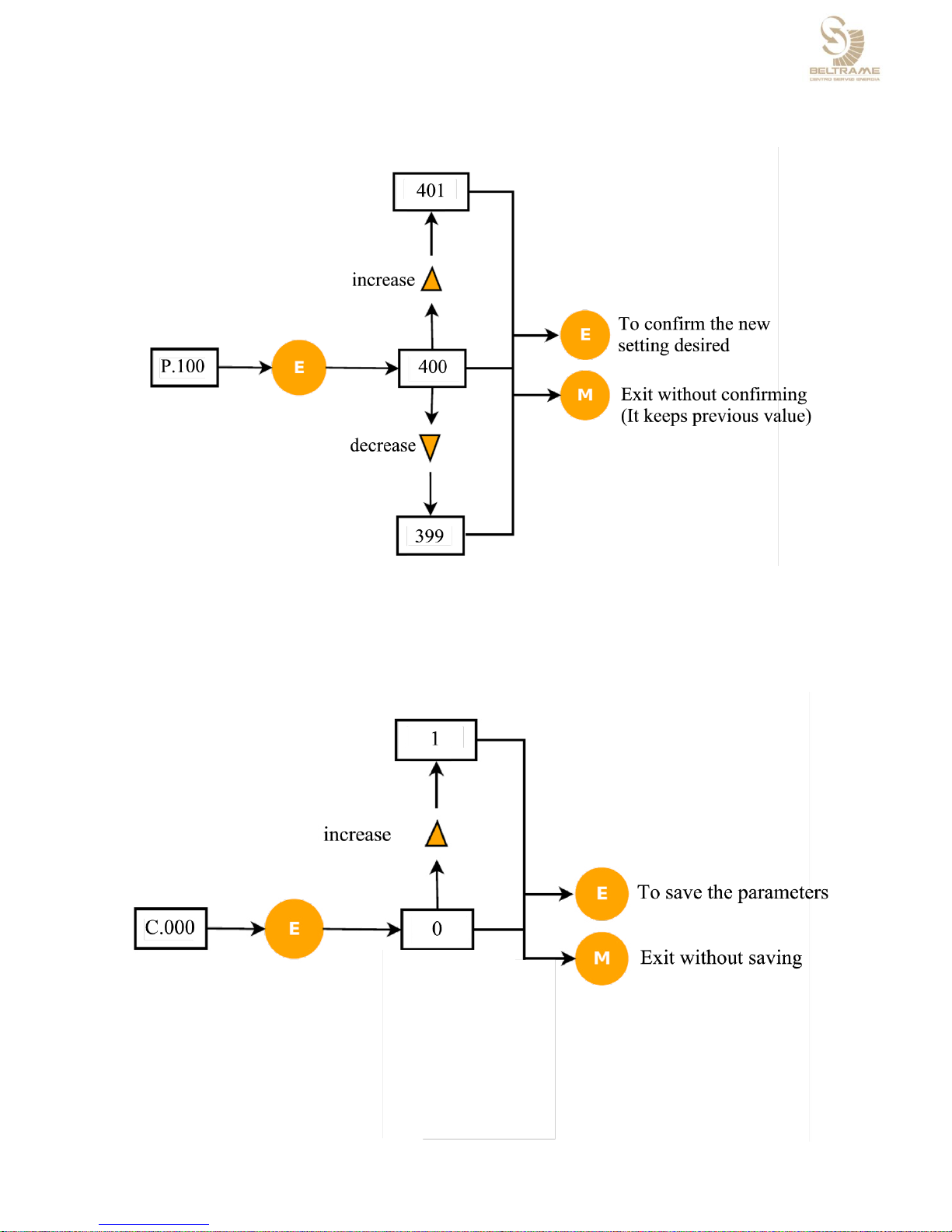
5.2 Navigating the menus
While the S2014 is working the parameter d000 is shown automatically in the Display
menu.
PAG. 25/32
Example: how to change a Rated voltage generator reference
5.3 Parameters saving
When a parameter is modified, the action is immediate. However the saving is not automatic
and needs to be done through a specific saving action, using the command “C.000” [save the
parameters].

PAG. 26/32
Menu
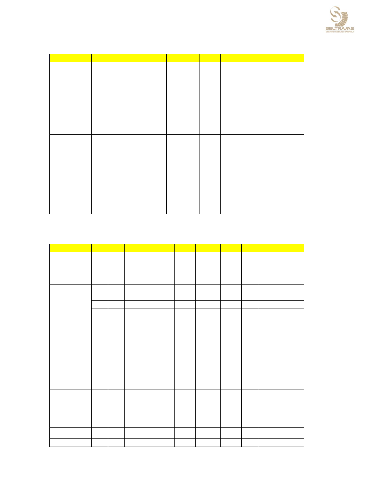
5.3.1 Menu d – Display
DISPLAYS
Name
IPA
Description
[U.M.]
Min
Default
Max
Notes, values
-1
Field
d.000
0
Field Current
%
0,0 - 200,0
% of P.000
d.020
1
Out Duty Cycle
%
0,0 - 100,0
1
Generator output
d.100
2
Gener. V
%
0,0 - -
% of P.100
d.104
3
Gener. Freq.
Hz
0,00 - 99,99
d.110
4
Gener. Current
%
0,0 - -
% of P.110
d.111
5
Gener. PowerFact
-
0,25 c - 0,25 i
Capacitive / Inductive
d.120
6
Gener. Power S
%
0,0 - -
% of P.100xP.110
d.121
7
Gener. Power P
%
-d.120 - d.120
% of P.100xP.110
d.122
8
Gener. Power Q
%
-d.120 - d.120
% of P.100xP.110
Excitier
d.950
9
FW ver. & rev.
- - - - xx.yy(hex)
d.952
10
SN
- - - - y.nnn
d.997
11
Heatsink Temp.
°C
-5 - 110
d.999
12
AUX V
V
0,0 - -
5.3.2 Menu r – References and Regulators
REFERENCES &
REGULATORS
Name
IPA
Description
[U.M.]
Min
Default
Max
Notes, values
199
Primary regulator
r.000
200
F. I digital ref
% 0 0,0
P.001
% of P.000
r.002
201
Ramp slope
%/s
0,1
50,0
999,9
r.010
202
Delta Ref calib
%
0
20
200
r.011
203
Delta Ref analog
%
0
20
200
r.012
204
Delta ramp slope
%/s
0,1
1,0
10,0
Field current
regulator
r.250
205
F. I Reg KP
-
0,01
0.50
99,99
r.251
206
F. I Reg TI
1/(2*AuxF)
0,1
20,0
100,0
related to Aux supply period
Generator voltage
regulator
r.350
207
G. V Reg KP
-
0,01
0.50
99,99
r.351
208
G. V Reg TI
1/(2*GenF)
0,1
20,0
100,0
related to generator period
206
Secondary
regulator
r.400
209
G. PF dig. ref
-
0,50c
1,00
0,50i
Capacitive / Inductive
r.401
210
G. VAR dig. ref
%
-100 0 100
% of P.100xP.110
r.402
211
Ramp slope
%/s
0,1
1,0
100,0
r.410
212
Delta Ref calib
%
0
20
100
r.411
213
Delta Ref analog
%
0
20
100
r.412
214
Delta ramp slope
%/s
0,1
1,0
10,0
PF/VAR
r.450
215
PF/VAR Reg KP
-
0,01
0,50
99,99
r.451
216
PF/VAR Reg TI
10/(2*GenF)
0,1
20,0
100,0
related to generator period
Aux voltage
regulator
r.650
217
AuxV Reg KP
-
0,01
0,50
99,99
r.651
218
AuxV Reg TI
1/(2*AuxF
0,1
20,0
100,0
related to Aux supply period
Limiters Regulator
r.900
219
OE/UE LIM Reg KP
-
0,01
0,25
99,99
r.901
220
OE/UE LIM Reg TI
1/(F reg)
0,1
40,0
100,0
related to generator period
PAG. 27/32
5.3.3 Menu I – Inputs and outputs
I/Os
Name
IPA
Description
[U.M.]
Min
Default
Max
Notes, values
Digital inputs
I.000
600
Dig inp 1 cnf
-
0 1 6
0 NONE
1 SET RAISE
2 SET LOWER
3 MANUAL FCR
4 GRID PAR (VDC)
5 GRID PAR (PF)
6 GRID PAR (VAR)
I.001
601
Dig inp 2 cfg
-
0 2 6
I.002
602
Dig inp 3 cfg
-
0 5 6
Digital outputs
I.100
603
Dig out 1 cnf
-
0 3 4
0 NONE
1 FAULT
2 NOT FAULT
3 LIMIT
4 NO LIMIT
RS485
I.400
604
RS485 config
-
0 0 4
0 custom protocol
1 Modbus RTU 8N1
2 Modbus RTU 8E1
3 Modbus RTU 8O1
4 Modbus RTU 8N2
I.401
605
RS485 bitrate
-
0 2 5
0 4800
1 9600
2 19200
3 38400
4 57600
5 115200
I.402
606
RS485 node ID
-
1 1 247
I.404
607
RS485 delay
s
0,000
0,001
0,100
5.3.4 Menu P – Parameters
PARAMETERS
Name
IPA
Description
[U.M.]
Min
Default
Max
Notes, values
Field excitation
data
P.000
1000
F. rated I
A dc
1,0
5,0
10,0
P.001
1001
F. OE Lim
%
100
150
250
% of P.000
P.002
1002
F. UE Lim
%
0 5 50
% of P.000
P.032
1003
F. OE Lim time
s
1
10
240
Generator data
P.100
1004
G. rated V
V rms
50
100
500
P.101
1005
G. max V
%
105
120
120
% of P.100
P.110
1006
G. rated I
A rms
0,20
2,50
5,00
P.130
1007
G. V/f min freq
Hz
20
30
150
P.131
1008
G. V/f max freq
Hz
P.130
45
250
P.132
1009
G. V/f slope
-
1,0
2,0
4,0
P.160
1010
Q – lim @ P 0%
%
-100
-40
-5
% of P.100 x P.110
P.161
1011
Q – lim @ P 25%
%
-100
-35
-5
% of P.100 x P.110
P.162
1012
Q – lim @ P 50%
%
-100
-30
-5
% of P.100 x P.110
P.163
1013
Q – lim @ P 75%
%
-100
-25
-5
% of P.100 x P.110
P.164
1014
Q – lim @ P 100%
%
-100
-20
-5
% of P.100 x P.110
P.170
1015
Q + lim @ P 0%
%
5
80
100
% of P.100 x P.110
P.171
1016
Q + lim @ P 100%
%
5
60
100
% of P.100 x P.110
Power supply
P.250
1017
KeepAlive min I
%
5
50
2
% of P.000
set 0 for PMG or
other independent
Power Supply
Control mode
P.300
1018
Primary reg.
-
0 1 1
0 FCR
1 AVR
Voltage Droop
Compensation
P.400
1019
Voltage comp K
%
-10,0
0,0
10,0
% of P.100 @ Q =
100%
Access control
P.981
1020
Password
-
0 1 9999
0 --> no password

PAG. 28/32
5.3.5 Menù C
DISPLAYS
Name
IPA
Description
[U.M.]
Min
Default
Max
Notes, values
-1
Utility commands
C.000
1600
Params save
-
0 0 1
C.002
1601
Params reload
-
0 0 1
C.200
1602
Test step
-
-8192 0 8192
8192=100%
C.201
1603
Test step type
-
0 1 3
0= Field I ref
1= Generator V ref
2= Generator PF ref
3= Generator VAR ref

PAG. 29/32
6. MAINTENANCE AND FAULTS
6.1 Safety regulations
WARNING!
The secondary voltage of the excitation transformer and the rotor field
voltage are fed into the excitation cabinet.
These components present a great danger of electric shocks.
Maintenance work shall only be carried out on the
electrical installation if the system has been switched off and protective
grounds installed.
6.2 Maintenance
When the system is at a standstill, check the fastening of faston terminals on the
regulator.
6.3 Trouble shooting
The following instructions are supposed to assist in localizing a fault within the
excitation system as a whole. However, it is not possible to deal with all eventualities
in full.
List of possible faults
Possible causes
Checks, action
Machine is not excited
Field circuit interrupted
Field circuit-breaker does not close
Check wiring for break
Check field circuit-breaker
No electronics supply
Measure power supply Aux – Com
Check for tripped protective circuit-breaker
Check builtin fuse
Set point error
Check operating mode
Check programmable digital input setting and
connection
Check set point
Overvoltage during build-up
Overvoltage caused by voltage regulator
Generator voltage present (measure voltage sensing
input at terminals Vsens and Common Aux)
Check system data
Check set point
Check overvoltage threshold
Check regulator settings
Machine voltage not stable in no-load operation

PAG. 30/32
Regulator error
Check operating mode.
Check programmable digital input setting and
connection
Check set points
Check parameters of voltage regulator
Set point error
Higher, lower inputs unstable
Externally input set point adjust unstable
Control element fault
Check wiring, loose contact V generator, Excitation
current
Parallel operation with grid unstable.
Periodic oscillation of reactive and possibly active power
Regulator settings incorrect
Were changes made to the grid configuration?
Are additional outputs, loads etc. installed?
Yes: re-set regulator
No: check parameters of Auto and PF, Var regulator
Irregular instability, i.e. sporadic over - or under excitation which is not
caused by grid
Droop influence of the voltage regulator
ineffective or CT measurement defective
Check droop compensation setting
Check external current transformer circuit
Gen CB Closed Status not active
Check programmable digital input setting and
connection
Machine within inadmissible operating range
(normally protected by limiters)
Bring machine into normal operating range by
adjusting the set point.
Check setting of limiters
Operating point cannot be adjusted
Set point error
Check operating mode.
Check programmable digital input setting and
connection
Check set point
Limiter active
Bring machine into normal operating range by
adjusting the set point.
Check setting of limiters
External controls faulty
No external control voltage
Measure control
voltage
Check wiring
Configuration of the digital or analog inputs are not
correct
Check configuration
6.4 Repair
A defective unit should be sent back for repair.

PAG. 31/32
7. GENERAL DATA
Ordering information
Device designation S2014
Mechanical data
Weight max 600 g
Protection class IP00 (limited by faston-type terminals, IP50 if terminals are protected
by an external isolation screen)
Dimensions (LxWxH) 138x58x55 mm
Climatic stability
Temperature range for operation: 0 to 55 °C
Temperature range for storage: -20 to +80 °C
Vibration: 5 mm, 2 G, 5<f<150 Hz
Electrical data
Power electronics supply: 80÷300Vac, 40 to 500 Hz
Excitation output: - maximum continuous current 8 A
- current reduction for ambient
temperatures >50 °C 1 A/degree
- overload (maximum 10 s) 16 A
Frequency range of measuring values Vgen and Igen 10 to 100 Hz
Accuracy: Voltage regulation <0.25%
Test voltage: power electronics supply against case 2500 Vdc, 2 s
Voltage measurement inputs Vgen, without galvanic separation
Relevant standards, CE conformity
EMC directive: 89/336/EEC
Generic emission standard EN 50081-2 (IEC 61000-6-4)
Generic immunity standard IEC/EN 61000-6-2

PAG. 32/32
Note:
 Loading...