

Page 1
Global Technical Operations
gto.gnresound.com
Lautrupbjerg 7 • DK-2750 Ballerup • Denmark
E-Mail: [email protected]
Technical Manual
Beltone
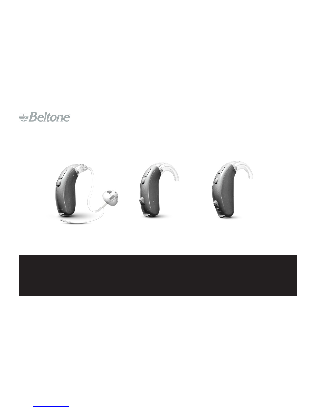
Paris Platform BTE
Page 2

Doc 0176160 rev. I
Page 2 of 19
Not subject to issue control when printed
Table of Contents
Form-Factor-Matrix ..............................................................................................................3
Colour Overview ..................................................................................................................4
Part List ......................................................................................................................... 5-10
Disassemble Procedure ....................................................................................................11
Replacing Toggle Cap .......................................................................................................12
Replacing Top HSG, Module, PB & Mic Cover ..................................................................13
Replacing Bottom HSG with ID Plate ................................................................................14
Service & Postponement Procedure .................................................................................15
Connecting the Programming Adaptor ..............................................................................16
Programming Adaptor Clip ................................................................................................17
Test Equipment ..................................................................................................................18
Testing ..............................................................................................................................19
Page 3
Doc 0176160 rev. I
Page 3 of 19
Not subject to issue control when printed
Form-Factor-Matrix
Platform Product Name Model Data Sheet
Paris 60 BTE
REACH 66 RCH66D 16649700
IDENTITY 66 IDT66D 16765400
Paris 70 BTE
REACH 76 RCH76D 16649800
REACH TBR (Tinnitus) 76 TBR76 16871900
IDENTITY 76 IDT76D 16765500
Paris 80 BTE
REACH 86 RCH86D 16649900
IDENTITY 86 IDT86D 16765600
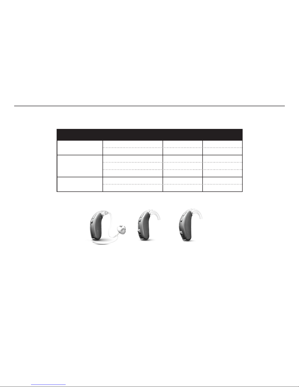
This Technical Manual serves to outline the service & postponement procedure for products listed in the form-factor-matrix below:
PARIS 60 PARIS 70 PARIS 80
Page 4
Doc 0176160 rev. I
Page 4 of 19
Not subject to issue control when printed
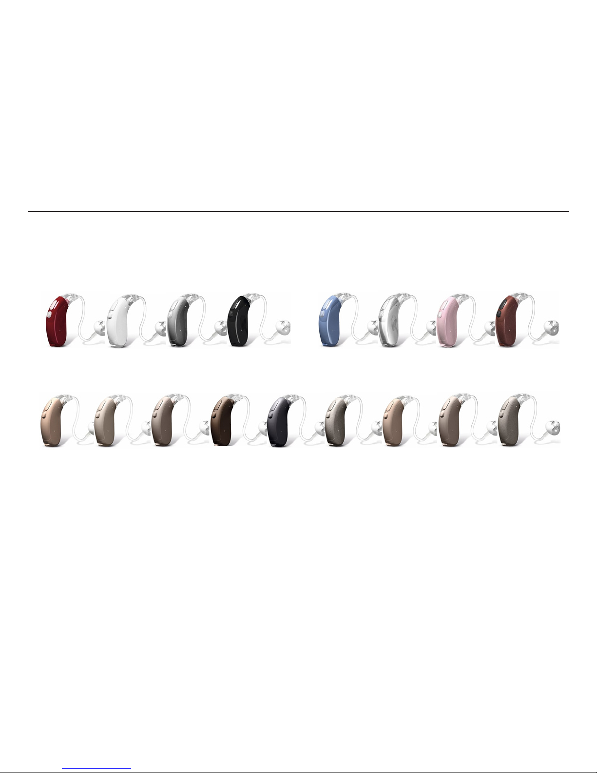
RUBY
RED
PRECIOUS
WHITE
MAJESTIC
SILVER
PRECIOUS
BLACK
DOVE BLUE CHROME ROSE PINK BRONZE
BEIGE LIGHT GREY GREY BROWN CHARCOAL STONE SOFT BEIGE SOFT GREY SOFT STONE
Colour Overview
Page 5
Doc 0176160 rev. I
Page 5 of 19
Not subject to issue control when printed
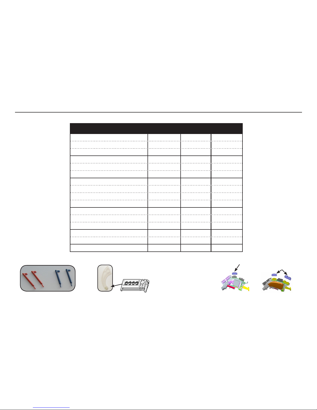
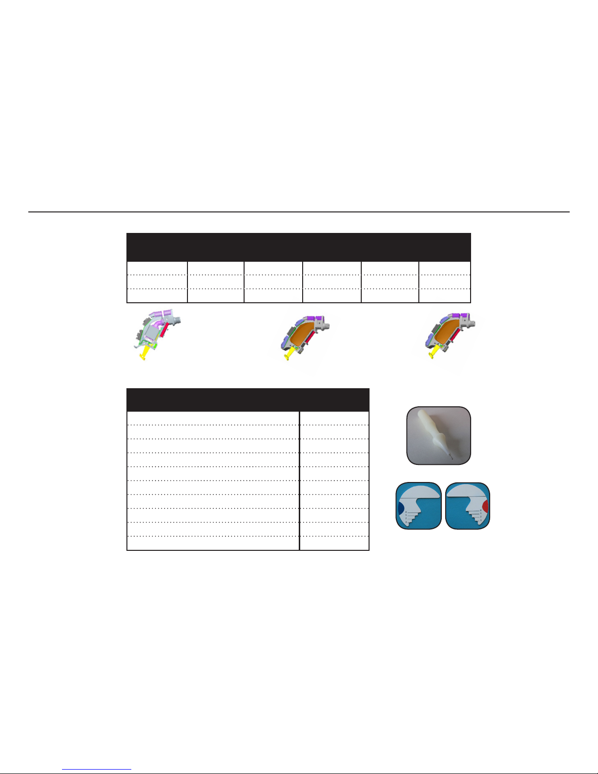
Description PARIS 60 PARIS 70 PARIS 80
CHILDLOCK, BLUE 16165801 15966401 15966401
CHILDLOCK, RED 16165800 15966400 15966400
THIN TUBE ADAPT 16187000 16187000 N/A
PIN Ø0.6 (Front) 15344200 16059700 16059600
PIN Ø0.6 (Rear) 16059800 15168000 16342400
PIN Ø0.6 (Bat door) 16059700 16059700 15344300
HOOK FILTER, 4 PCS 16166700 16166700 N/A
TONE TUBE ADULT (no lt) 16186700 16186700 16186700
TONE TUBE BABY (no lt) 16186900 16186900 16186900
TONE TUBE CHILD (no lt) 16186800 16186800 16186800
TONE TUBE ADULT (w/lt) 17044100 17044100 N/A
TONE TUBE BABY (w/lt) 17044300 17044300 N/A
TONE TUBE CHILD (w/lt) 17044200 17044200 N/A
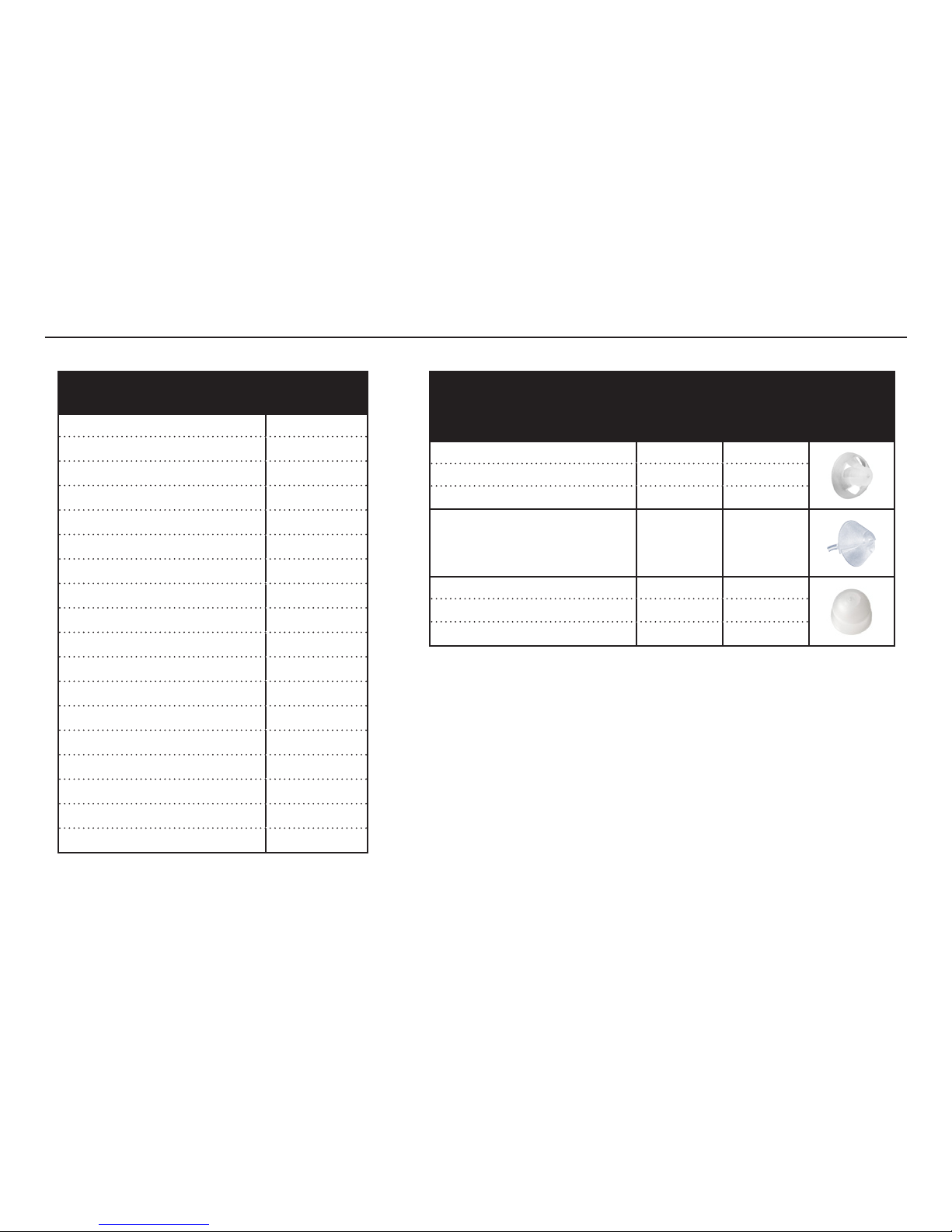
PB CAP, SINGLE 15967300 15967300 15967300
PB CAP, DOUBLE N/A 15967400 15967400
AUDIO BOOT 18330400 18330500 18330600
PARIS 70/80
PB CAPS
(single & double)
PARIS 60
PB CAP (single)
4 pcs Hook Filter
p/n 16166700
Hook lter is to be mounted in
tone tubes for Paris 60 & 70 only
Tone tubes for PARIS 80 must
always be without lter
Part List
Colour markers
Page 6
Doc 0176160 rev. I
Page 6 of 19
Not subject to issue control when printed
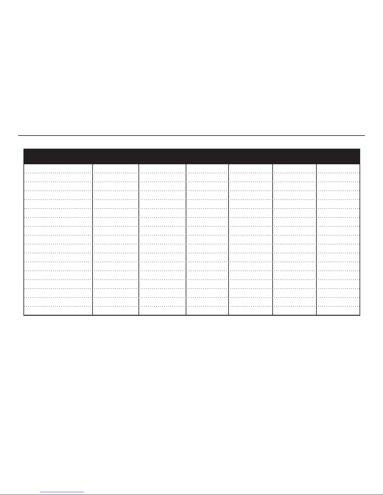
Description Part No
PROG. ADAPTOR 18041400
TEST FIXTURE 16695100
TEST FRAME 16902800
CS44 PROGRAMMING CABLE (R) 9022 907 69019
CS44 PROGRAMMING CABLE (L) 9022 907 69029
CLIP,PROGRAMMING ADAPTOR,RED 17736900
CLIP,PROGRAMMING ADAPTOR,BLUE 17736901
MEASSUREMENT TOOL 15200800
PIN REMOVAL TOOL 15502500
TOGGLE REMOVER (Paris 70/80) 16167000
Service modules are none serviceable at local site. Instead defective service modules must be returned to Global Repair Site
Part List
Service Modules (ASM FRAME, PROGRAMMED):
PARIS 60 PARIS 70 PARIS 80
RCH66D 16911600 RCH76D 16911800 RCH86D 16962000
IDT66D 16911700 IDT76D 16911900 IDT86D 16962100
TBR76 16912000
Pin removal tool
Measurement tool 15200800 for
both left and right side
Page 7
Doc 0176160 rev. I
Page 7 of 19
Not subject to issue control when printed
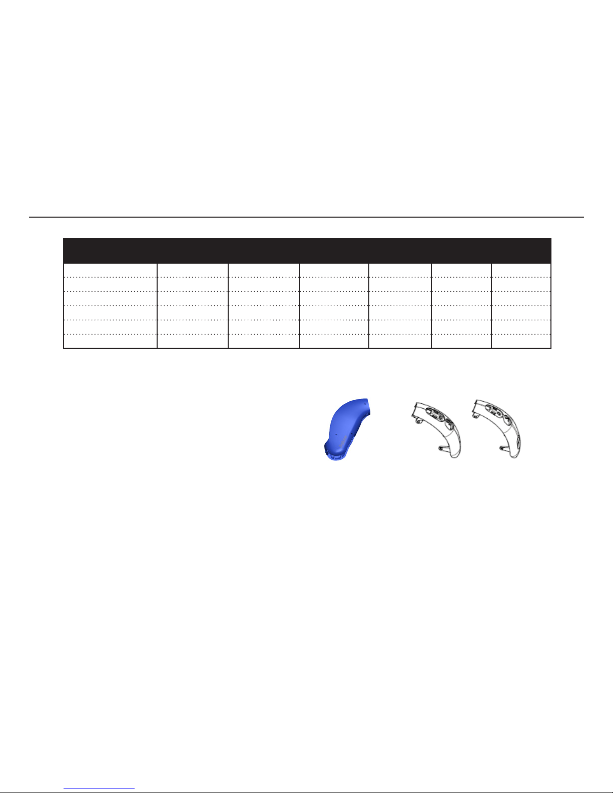
HI Colour
Description
PARIS 60/70/80
Mic Cover
PARIS 60/70/80
Actuator PB
PARIS 70/80
Toggle VC
PARIS 70/80
VC Cover
PARIS 60
Batt Door
PARIS 70/80
Batt Door
BEIGE 16186100 16960100 16187500 16381900 16386400 16387400
GREY 16186101 16960101 16187501 16381901 16386401 16387401
LIGHT GREY 16186102 16960102 16187502 16381902 16386402 16387402
BROWN 16186103 16960103 16187503 16381903 16386403 16387403
CHARCOAL 16186104 16960104 16187509 16381910 16386419 16387419
STONE 16186105 16960105 16187505 16381905 16386405 16387405
SOFT BEIGE 16186100 16960100 16187500 16381900 16386406 16387406
SOFT GREY 16186101 16960101 16187501 16381901 16386407 16387407
SOFT STONE 16186105 16960105 16187505 16381905 16386408 16387408
PRECIOUS BLACK 16186106 16960106 16187506 16381906 16386409 16387409
PRECIOUS WHITE 16186107 16960107 16187507 16381909 16386410 16387410
MAJESTIC SILVER 16186121 16960107 16187507 16381909 16386411 16387411
BRONZE 16186106 16960106 16187506 16381906 16386412 16387412
DOVE BLUE 16186121 16960107 16187507 16381909 16386413 16387413
RUBY RED 16186121 16960107 16187507 16381909 16386414 16387414
ROSE PINK 16186121 16960107 16187507 16381909 16386415 16387415
CHROME 16186121 16960107 16187507 16381909 16386416 16387416
Note:
The description in left column is the colour description for the HI & Replacement Kits. In some cases an e.g. transparent Mic cover is used in various HI colours and is therefore listed more than one time
Separate HSG parts are not nano coated
Part List - Housing Parts
Page 8
Doc 0176160 rev. I
Page 8 of 19
Not subject to issue control when printed
HI Colour
Description
PARIS 60
HSG Bottom
PARIS 70
HSG Bottom
PARIS 80
HSG Bottom
PARIS 60
HSG Top
PARIS 70
HSG Top
PARIS 80
HSG Top
BEIGE 16184400 16184500 16184600 16187700 16187200 16187900
GREY 16184401 16184501 16184601 16187701 16187201 16187901
LIGHT GREY 16184402 16184502 16184602 16187702 16187202 16187902
BROWN 16184403 16184503 16184603 16187703 16187203 16187903
CHARCOAL 16184404 16184504 16184604 16187704 16187204 16187904
STONE 16184405 16184505 16184605 16187705 16187205 16187905
Note:
Only the above HSG parts are available as separate
spare parts. Parts in other colours must be ordered as
a replacement kit. The description in left column is the
colour description for the HI & Replacement Kits.
Separate HSG parts are not nano coated
HSG Bottom
HSG Top
Part List - Housing Parts
Page 9
Doc 0176160 rev. I
Page 9 of 19
Not subject to issue control when printed
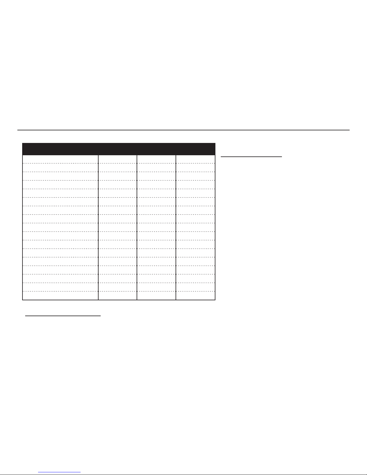
Replacement Kit - colour PARIS 60 PARIS 70 PARIS 80
BEIGE 16400000N 16400100N 16400200N
GREY 16400001N 16400101N 16400201N
LIGHT GREY 16400002N 16400102N 16400202N
BROWN 16400003N 16400103N 16400203N
CHARCOAL 16400004N 16400104N 16400204N
STONE 16400005N 16400105N 16400205N
SOFT BEIGE 16400006N 16400106N N/A
SOFT GREY 16400007N 16400107N N/A
SOFT STONE 16400008N 16400108N N/A
PRECIOUS BLACK 16400009N 16400109N N/A
PRECIOUS WHITE 16400010N 16400110N N/A
MAJESTIC SILVER 16400011N 16400111N N/A
BRONZE 16400012N 16400112N N/A
DOVE BLUE 16400013N 16400113N N/A
RUBY RED 16400014N 16400114N N/A
ROSE PINK 16400015N 16400115N N/A
CHROME 16400016N 16400116N N/A
Replacement kit contains:
- Top-housing
- Bottom housing
- Battery door
- Push-button cap/actuator
- VC toggle (PARIS 70/80)
- VC cover (PARIS 70/80)
- Mic Cover
- Housing Pins
Replacement kits are nano coated
Mounting the Replacement Kits:
Please refer to Doc 0173460:
WORKING INSTRUCTIONS,REPLACEMENT KITS, BELTONE PARIS BTE PLATFORM
Part List - Replacement Kit (nano coated)
Page 10
Doc 0176160 rev. I
Page 10 of 19
Not subject to issue control when printed
THIN TUBE BLISTER PACKS
(5 tubes & 3 cleaning wires)
Part No
THIN TUBE 2,0A,R,BLSTR 18628600
THIN TUBE 2,0B,R,BLSTR 18628700
THIN TUBE 2,1A,R,BLSTR 18628800
THIN TUBE 2,1B,R,BLSTR 18628900
THIN TUBE 2,2A,R,BLSTR 18629000
THIN TUBE 2,2B,R,BLSTR 18629100
THIN TUBE 2,3A,R,BLSTR 18629200
THIN TUBE 2,3B,R,BLSTR 18629300
THIN TUBE 2,-1B,R,BLSTR 18629400
THIN TUBE 2,0A,L,BLSTR 18629500
THIN TUBE 2,0B,L,BLSTR 18629600
THIN TUBE 2,1A,L,BLSTR 18629700
THIN TUBE 2,1B,L,BLSTR 18629800
THIN TUBE 2,2A,L,BLSTR 18629900
THIN TUBE 2,2B,L,BLSTR 18630000
THIN TUBE 2,3A,L,BLSTR 18630100
THIN TUBE 2,3B,L,BLSTR 18630200
THIN TUBE 2,-1B,L,BLSTR 18630300
THIN TUBE DOMES
Description
Bag
(10 pcs)
Blister Pack
(8 pcs)
DOME,THNTUB/REC,SZ5,SM 18500800 18607100
DOME,THNTUB/REC,SZ7,MDM 18500900 18607200
DOME,THNTUB/REC,SZ10,LGE 18501000 18607300
DOME,THNTB/REC,TULIP,STD 18501100 18607400
DOME,THNTUB/REC,PWR,SM 18265100 18607500
DOME,THNTUB/REC,PWR,MDM 18265200 18607600
DOME,THNTUB/REC,PWR,LGE 18265300 18607700
Part List - Thin Tubes & Domes
Page 11
Doc 0176160 rev. I
Page 11 of 19
Not subject to issue control when printed
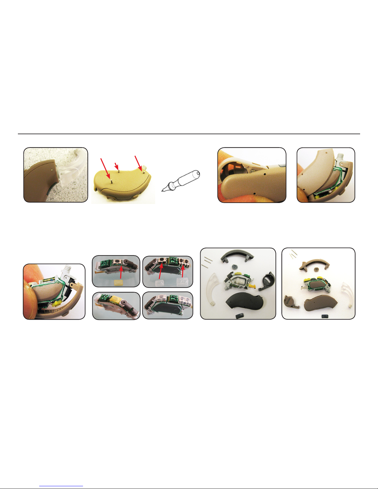
Pin removal tool packed
w/user instructions
p/n 15502500
Long pin
Short pin
Remove the hook by turning
it counter clockwise
Remove the 3 pins from
HSG using pin removal tool
Remove battery door Remove the bottom HSG
Remove the module from
the top HSG
Make sure the silicone caps are correct in
place before mounting HSG parts
PARIS 60 PARIS 70/80
PARIS 60 PARIS 70/80 (70 is shown)
Batt pin
Disassemble Procedure
Page 12
Doc 0176160 rev. I
Page 12 of 19
Not subject to issue control when printed
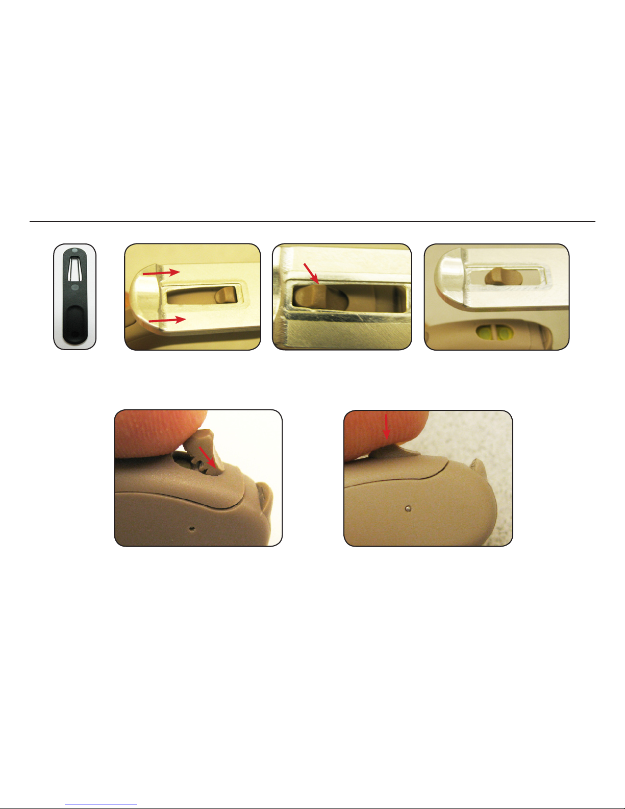
Place the widest gap on the tool on the top of the toggle switch cap. Slowly slide the tool as shown until the cap is
trapped. Then continue sliding the tool until the cap is off
Mount the new toggle switch cap by inserting
the lower part of the cap as shown
Press the top part of the cap into the device to
lock it
Replacing VC Toggle
Toggle remover
Page 13
Doc 0176160 rev. I
Page 13 of 19
Not subject to issue control when printed
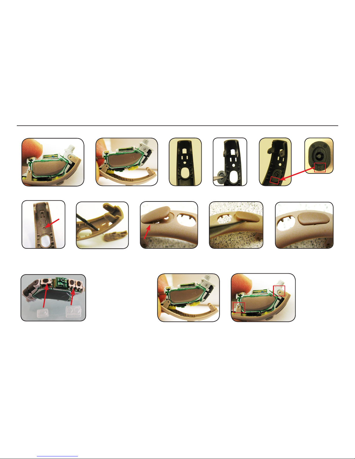
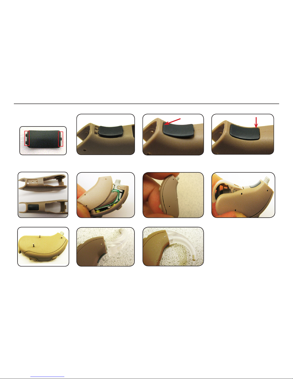
Separate the module from the top housing. Note that the PB
cover is not glued to the top HSG
Gently push out PB cover from top HSG (from outside). When mounting the new
PB cover, make sure bottom part of PB cover is placed properly
Before mounting the new top
HSG to the new module, make
sure the transp covers are
mounted to the module
Push out mic cover from
top HSG
When mounting the new mic
cover, insert left side wing rst
Gently push right side wing in place and slowly press the mic
cover in place. Be carefull not to damage any of the wings
Place bottom part of the module on the top HSG. Insert top part
of module until pin holes are aligned
Top HSG with hole to
push out the mic cover
Replacing Top HSG, Module, PB & Mic Cover
Page 14
Doc 0176160 rev. I
Page 14 of 19
Not subject to issue control when printed
Place ID plate in the new bottom HSG. Insert the side with two prong rst and then one prong side
Old Bottom Housing
New Bottom Housing
0812345678
One prong
Two prong
RCH76D
Gently close the assembly and add the batt door
Add the hook and turn it clockwise to lock it in placePlace the 3 locking pins and
press them down
Add bottom housing part
ID plate
Note that ID plate is NOT
an available pare part
Replacing Bottom HSG with ID Plate
Page 15

Doc 0176160 rev. I
Page 15 of 19
Not subject to issue control when printed
Service Procedure:
- Save user settings with Device Diagnostics or Solus
- Disassemble faulty device
- Replace module with a new service moduel from stock
- Assemble device
- Restore user settings with Device Diagnostics or Solus
- Load customer serial no (ID Plate) using Device Diagnostics or DSA6000
Postponement Procedure:
- Disassemble device
- Replace parts with replacement kit from stock
- Transfer ID-plate from old housing to new housing
- Verify battery door by open and close once
For detailed process refer to Doc 0173460:
WORKING INSTRUCTIONS,REPLACEMENT KITS, BELTONE PARIS BTE PLATFORM
Service & Postponement Procedure
Page 16
Doc 0176160 rev. I
Page 16 of 19
Not subject to issue control when printed
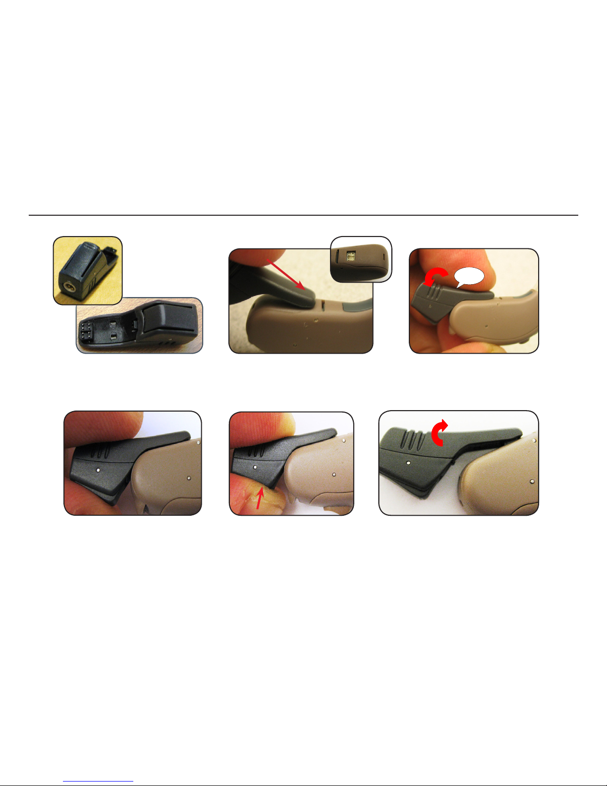
Insert the one end of the prog adaptor into
the square programming port of the device
Push the bottom part of the prog adapt
until it clicks to lock it on the device
Push the button to unlock the prog adaptor from the battery door Gently peel off the prog adapt from the HI
Click
Connecting the Programming Adaptor
Page 17
Doc 0176160 rev. I
Page 17 of 19
Not subject to issue control when printed
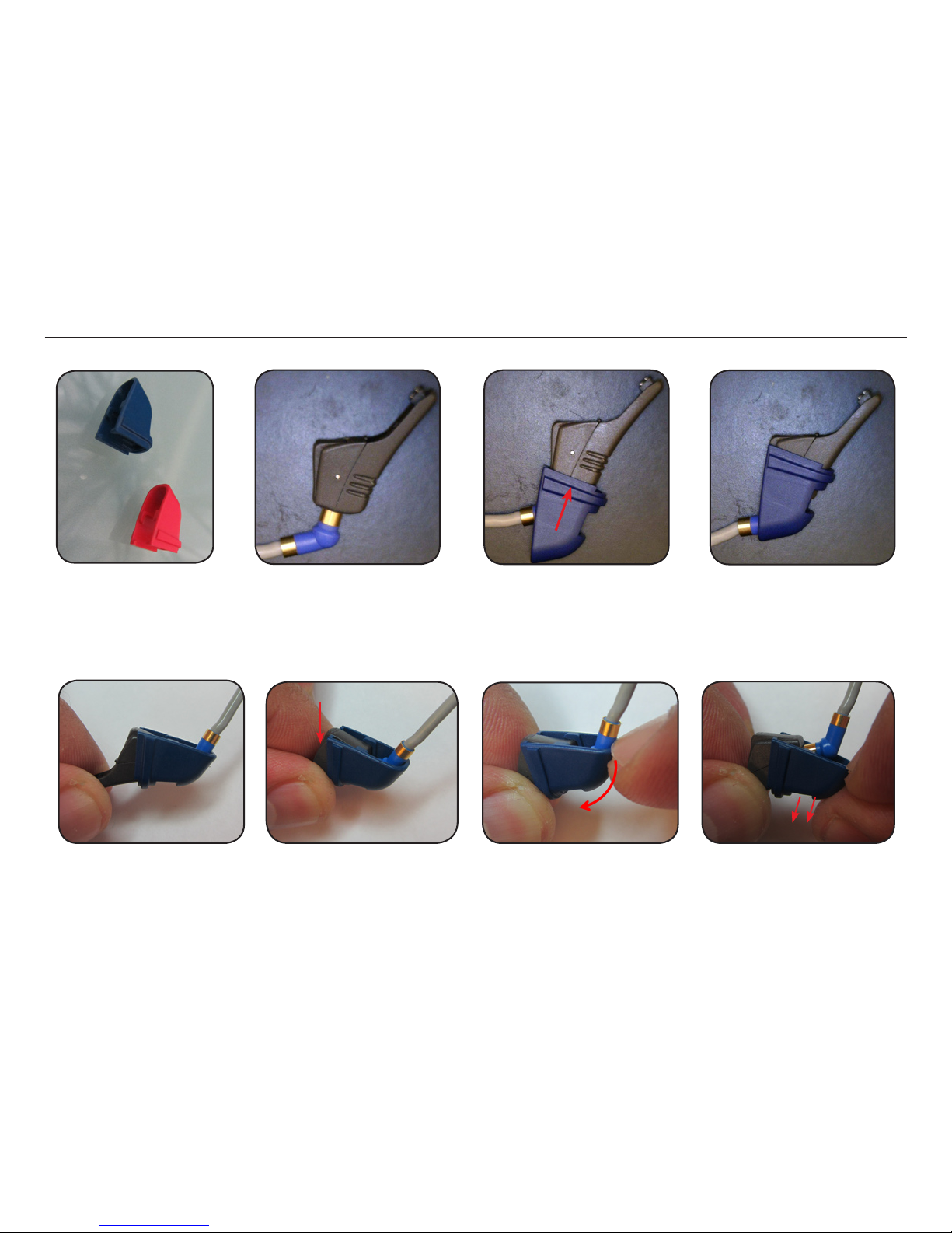
To remove the clip rmly grip this side of prog adapt Pull tip of the clip Slide the clip from adaptor
It is important to have the programming cable connected before adding the clip to the programming adaptor.
Add the clip as shown in the pics. The clip is recommended to be used during test / tting in order to keep the
prog cable connected during the complete procedure
Clip for prog adaptor L/R
Programming Adaptor Clip
Page 18
Doc 0176160 rev. I
Page 18 of 19
Not subject to issue control when printed
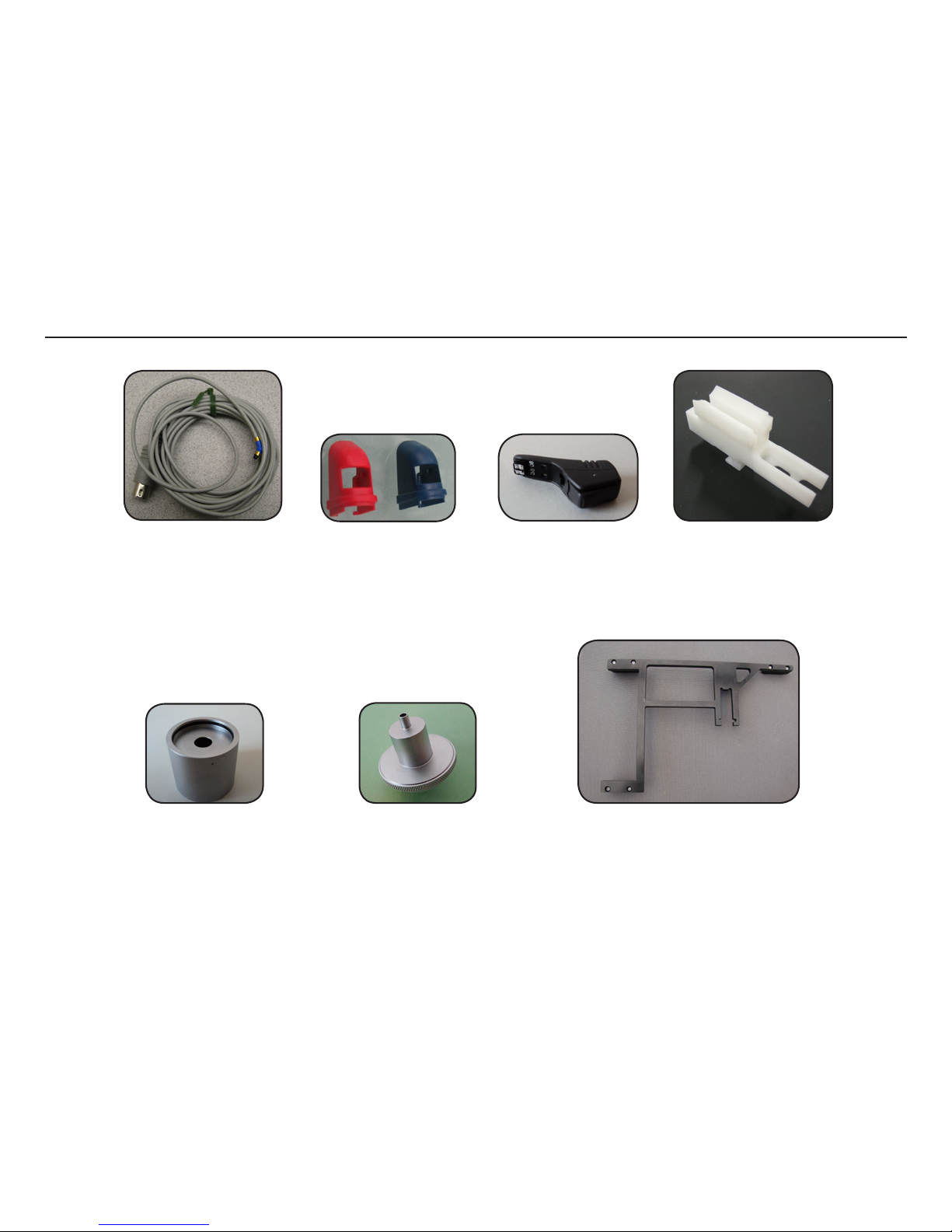
Prog adaptor clip
17736900 Red
17736901 Blue
Test frame p/n 16902800
Prog adaptor
p/n 18041400
(incl red & blue clip)
2cc coupler
p/n 30-4838800
(can be ordered with GTO Dept/
HQ Ballerup DK)
2cc coupler insert BTE
p/n 40B4609601
(can be ordered with GTO Dept/
HQ Ballerup/DK)
Instrument xture
p/n 16695100
for nal HI test
CS44 Prog cable
(Left blue is shown)
9022 907 69019 (R)
9022 907 69029 (L)
Test Equipment
Page 19
Doc 0176160 rev. I
Page 19 of 19
Not subject to issue control when printed
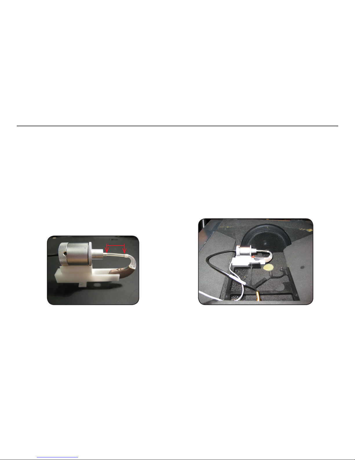
Use of the test xture is mandatory for all Paris Platform BTE during AUDIOmaster testing.
To use the xture, place the instrument under test in the xture according to picture.
Connect the programming cable to the programming adaptor and then attach the programming adaptor to the device.
Select test program in AUDIOmaster and press ‘Start’
During the test program execution the IAD calibration will be performed at the appropriate time. Another benet from the xture is that
the instrument is in a well dened position so the telecoil test can be performed without any interaction from the operator.
Test tubing is 20 mm effective length as for
all AUDIOmaster BTE testing
Place device in test chamber as shown
20mm
Testing
 Loading...