

Page 1

Technical Manual
Beltone EazyTrim Plus BTE
EZTP73-V BTE
Global Technical Operations
gto.gnresound.com
Lautrupbjerg 9 • DK-2750 Ballerup • Denmark
E-Mail: [email protected]
Page 2

Doc. No. 0121820 rev. B
Page 2 of 8
Table of contents
Description...........................................................................................................................3
Part list.................................................................................................................................4
Dis-assembly HI ..................................................................................................................5
Microphone & Receiver ................................................................................................... 6-7
Mounting PB Battery Springs & Telecoil ..............................................................................8
Page 3

Doc. No. 0121820 rev. B
Page 3 of 8
Description
The Beltone EZ TRIM PLUS offers the benets of modern digital technology with the ease of conventional tting. The
Beltone EZ TRIM PLUS is an easy adjustable BTE with digital signal processing that does not require computer or tting
software. Fitting is done by using the four digital trimmers, allowing you to do a personal and easy t:
• Low Frequency control (green)
• Threshold Kneepoint control (blue)
• Maximum Power Output control (black)
• Programme Selection (orange)
Product featuring:
• 100% digital signal processing
• 4 channels
• Easy tting
• Adaptive feedback manager
• Adaptive noise reduction
• Low battery warning
• Analogue Volume Control
• Battery size 13
• Long battery life
• Wide band AGC-O (output compression)
Please also see Technical Data Sheet / Product Information Doc 15997900
Page 4

Doc. No. 0121820 rev. B
Page 4 of 8
Part List
HI Complete EZTP73-V Part No.
BEIGE 15985300
GREY 15985302
BROWN 15985303
Accessories Part No.
SPECTACLE ADAPTOR 15951800
SCREWDRIVER (FOR TRIMMERS) 8090-369
Item Part No.
AMP (COMPL IN FRAME) 16015100
T-COIL-HOLDER INTEGRA 513-010-100-01
T-COIL Y21 INTEGRA,S-VDD/ NANO 576-002-080-00
PB SWITCH 611-000-010-00
BATT. CONTACTS +/- 562-009-000-01
HOUSING PTD, BGE, EZTP73-V 16305200
HOUSING PTD, GREY, EZTP73-V 16305202
HOUSING PTD, BROWN, EZTP73-V 16305203
HSG-FRONTCAP (FACETTE) 502-004-100-05
BATT.DOOR (NOIMPRINT) GR 503-003-100-05
TRIMMER COVER 504-037-100-05
EARHOOK #7 (QU-EVO) 556-007-004-00
MIC COMPL MOUNT W/WIRES,SUSP 612-001-001-23
MIC SUSPENSION INTEGRA 551-002-000-00
WIRE,ESW,RED,7X32U,18MM 15129618
WIRE,ESW,AMBER,7X32U,18MM 15129718
WIRE,ESW,GREEN,7X32U,18MM 15129818
MIC EK-3024 CX 612-001-001-01
Item Part No.
REC COMPL MOUNT W/WIRES,SUSP 613-004-001-33
REC SUSPENSION INTEGRA 550-003-000-00
WIRE,ESW,RED,7X32U,23MM 15129623
WIRE,ESW,AMBER7X32U,23MM 15129723
RECEIVER EF-7505 15301800
COATING KR112 9500-719
Page 5
Doc. No. 0121820 rev. B
Page 5 of 8
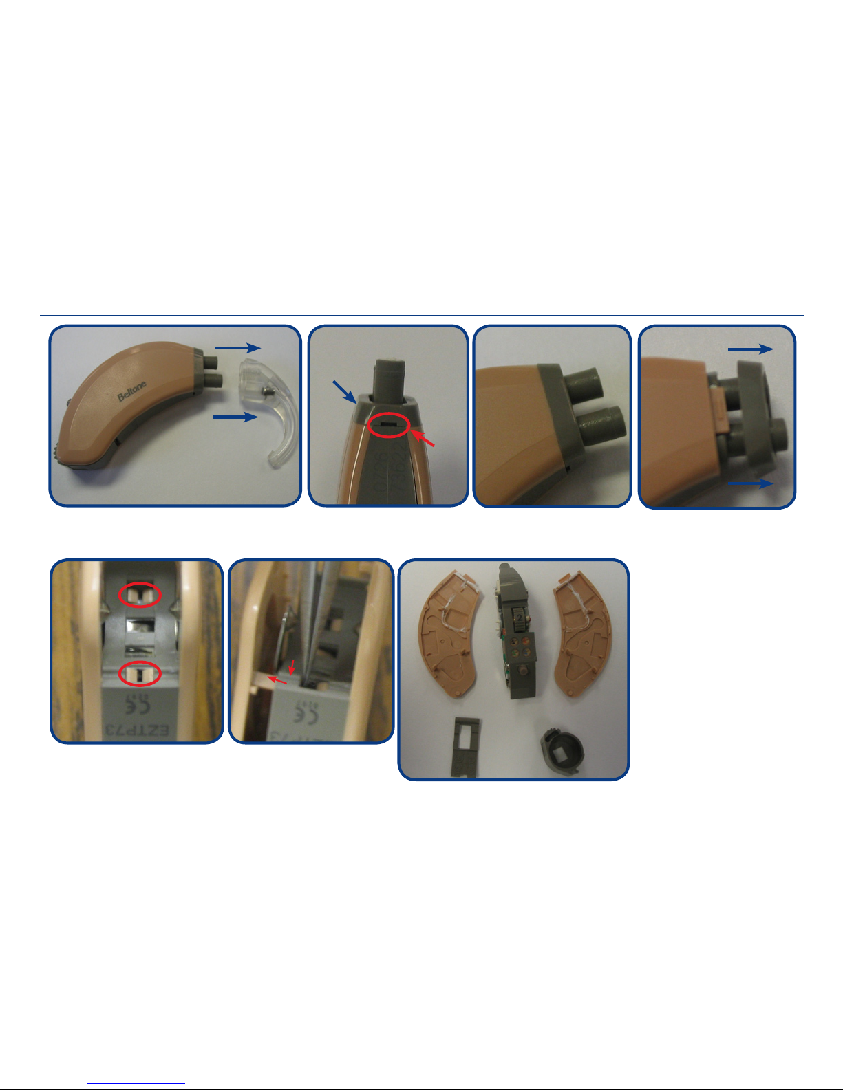
Dis-assembly HI
Pull out the ear hook
Insert a screwdriver in the
slot to release the front cap
Slot
Front cap
Gently remove the front cap
Open batt door. To release the housing upper/lower
parts, push the housing plastic locks by using a tweezer
(one side at a time)
Gently separate the housing
parts from frame as shown.
Tip:
Open the batt. door and use
that opening to separate the
housing parts
Page 6
Doc. No. 0121820 rev. B
Page 6 of 8
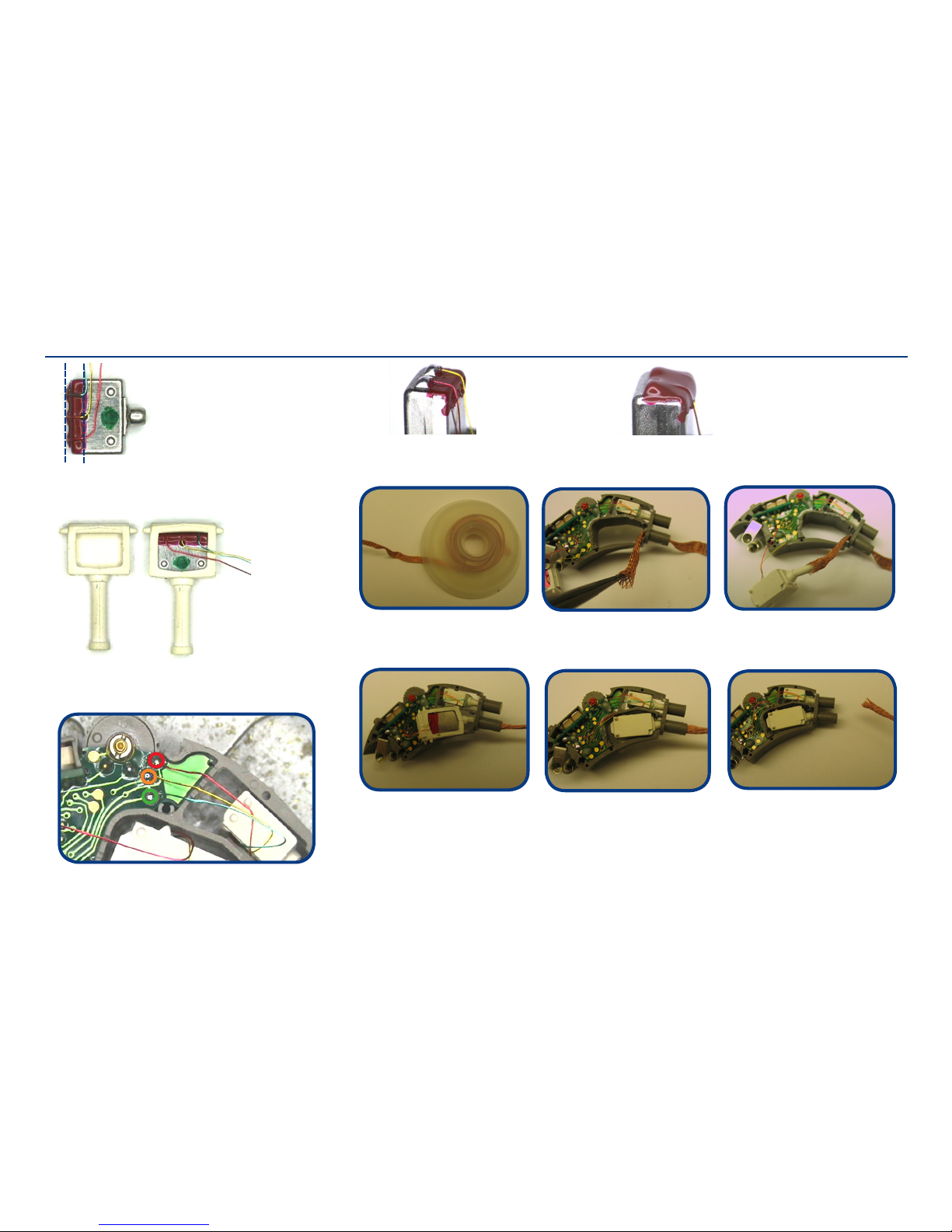
Microphone & Receiver
Mic complete
p/n 612-001-001-23
Mic wires are connected and placed as shown
The mic is covered in the
indicated area by standard nail
varnish to protect the mic and
to keep the wires in place
Bend the wires as shown
before mounting the mic into
suspension
The rec is covered
with standard nail
varnish to protect the
rec. Solder the wires
as shown
The rec is covered with a
second layer to protect the
soldering pads and to keep the
wires in place. Mount the rec
into suspension
Mounting the rec into housing (same procedure goes for the mic):
Get a solder wick. Insert wick into the receiver hole of the frame (from outside to inside).
Using a tweezer, open the wick like a “tube opening”. Place the end of the rec tube into the
“tube” opening of the wick. Compress the wick tube opening to collapse into the rec tube
Pull the outside end of the wick taking along the rec tube. Remember to position the metal
side of the rec upwards so twist while pulling the wick if necessary to position the rec in
the frame. Pull the wick all the way through until the end of the rec tube is through. Then
the wick will disengage from the rec tube. It may extend the tip of the rec tube a bit, but
you can push it back in place.
Page 7
Doc. No. 0121820 rev. B
Page 7 of 8
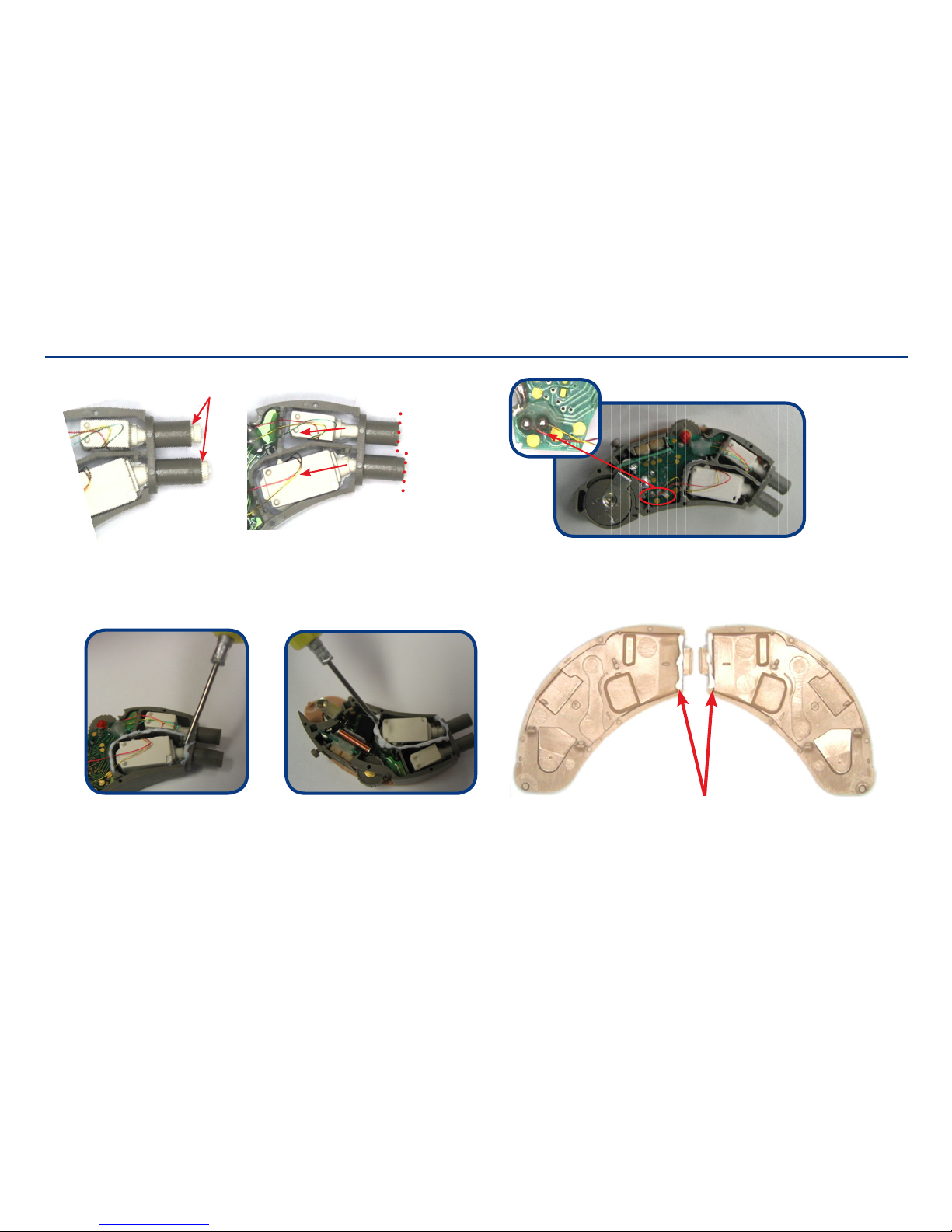
Microphone & Receiver
Add grease/Molycote on both housing parts
Add grease/Molycote onto the edge of both sides of the receiver compartment
Gabs
Pull back till suspensions
ush with dotted line
Connect and place the rec wires as shown
Page 8
Doc. No. 0121820 rev. B
Page 8 of 8
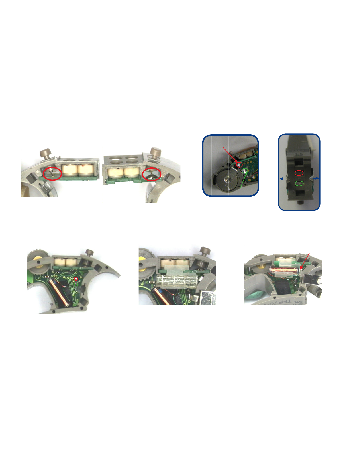
Replacing PB Battery Springs & Telecoil
Amplier is shown from both sides
Soldering points for the two PB terminals
Soldering points for TC
Telecoil holder is attached to trimmer
PCB and added a double sided tape
to keep the TC in place
Make sure the TC does not touch
the battery spring
Keep a small gab
Unsolder the battery
springs from the PCB
To release the contacts
from the BTE frame,
push the encircled area
and lift out the spring/
contacts
(+)
(-)
Batt spring (+)
Batt spring (-)
 Loading...