

Page 1

233227 - 1
Installation and Operation Manual
4-Pan Convection Oven, Gas
Model Nbr: BACO32G
Page 2

The reproduction or copying of any part of this manual by any means whatsoever is strictly forbidden unless authorized previously in
writing by the manufacturer.
In line with policy to continually develop and improve its products, Belshaw Adamatic, reserves the right to change the specifications
and design without prior notice.
© Copyright Belshaw Adamatic. April 2009.
Page 3

US/Canada/Mexico Limited Warranty and Return Policy
Belshaw Adamatic Bakery Group warrants parts of its manufacture and assembly of equipment to be free
from defects in workmanship and material which would result in product failure under normal use and
service. Belshaw Adamatic Bakery Group’s entire liability under this Warranty is limited to either repairing
or replacing at its factory or; on user’s premises, at Belshaw Adamatic Bakery Group’s option, any
equipment or parts thereof, which shall be determined by Belshaw Adamatic Bakery Group to be defective.
If necessary to return parts to the factory they must be shipped transportation charges prepaid. This
shall be purchaser’s sole and exclusive remedy.
Belshaw Adamatic Bakery Group reserves the right to make changes in design, or add any improvement, at
any time without incurring any obligations to install the same, on equipment previously sold.
This warranty is expressly in lieu of any and all other warranties express or implied, including:
implied warranties of merchantability and fitness for any particular purpose, and all other
obligations or liabilities what so ever on Belshaw Adamatic Bakery Group’s part. All statutory
or implied warranties, other than title, are expressly nullified and excluded.
Belshaw Adamatic Bakery Group neither assumes nor authorizes any person to assume for it
any obligation or liability in connection with the sale of its products or parts thereof.
Possession, use/or operation of equipment, or parts sold hereunder for any other than their designed
purpose, or use of equipment which is in poor repair, modified, improperly operated, or neglected is done
at the owner’s risk. Belshaw Adamatic Bakery Group hereby disclaims any liability for these actions and
shall not be liable for defects in or for any damages or loss to the property sold which is attributable to
such actions.
Under no circumstances shall Belshaw Adamatic Bakery Group be liable for any indirect,
special, incidental, or consequential damages arising out of, or from the use of Belshaw
Adamatic Bakery Group’s product by buyer, it assignees, employees, agents or customers.
Belshaw Adamatic Bakery Group makes no express warranties except those contained in this Warranty
concerning the product sold hereunder. No modification or alteration of this Warranty shall be made
except by Belshaw Adamatic Bakery Group in writing.
Warranty Period / Guidelines
This limited warranty shall extend for a period of one year from date of shipment and to the original owner
only. It covers parts (manufactured by Belshaw Adamatic Bakery Group) and labor. This warranty covers
only items sold within the United States, Canada and Mexico. A pre-authorization must be obtained from
Belshaw Adamatic Bakery Group before any warranty work is carried out, failure to do so may void the
warranty of the product.
Belshaw Adamatic Bakery Group www.belshaw-adamatic.com Phone (206) 322-5474 Fax: (206) 322-5425
Revised 03/10/2007 US / Canada / Mexico Limited Warranty Page 1 of 2
Page 4

Belshaw Adamatic Bakery Group www.belshaw-adamatic.com Phone (206) 322-5474 Fax: (206) 322-5425
Revised 03/10/2007 US / Canada / Mexico Limited Warranty Page 2 of 2
Limited Warranty
With respect to parts not manufactured by Belshaw Adamatic Bakery Group, warranty coverage shall be
limited to the original part manufacturer’s warranty, or the Belshaw Adamatic Bakery Group limited
warranty, whichever is the lesser coverage period. In no case will the warranty be in excess of 18 months
after date of shipment of the equipment.
Replacement parts provided under the terms of this warranty are warranted for the remainder of the
original warranty period applicable to the product.
Exclusions:
This warranty excludes from its coverage and does not apply to: (a) solenoid and relay coils; (b) lamps;
(c) “O” rings; (d) belts; and (e) impellers. These items are excluded because (1) failure is usually due to
causes beyond our control; (2) it is not practical to accurately determine the failure cause; and (3) the
normal life of the parts is shorter than our warranty period.
Procedure for Return:
To speed up your credits for returned equipment, we have a return goods policy and procedure. Our
procedure starts with a phone call to (206) 322-5474 or Service Department for a return authorization.
When contacting Service Dept. you should be ready to give:
• Customer name, address, phone number and individual’s name, Invoice number and date, Model
number and serial number, reason for return (i.e. credit, exchange, warranty, or repair), description
of item, and problem.
When we get this information we will issue you a Return of Goods Authorization Number (RGA). This
number must be marked clearly on the outside of the package. If the package is not clearly marked with
the RGA#, then the package will be returned unopened to the sender. The RGA# will be open for 30 days,
if returnable goods have not been received within the 30 days, then RGA# will be voided.
Return goods must be:
• Returned freight prepaid, packaged securely and carefully so that in-transit damage cannot occur.
• Marked so the package contains the RGA# in the first line of the address line, “Attn: RGA#” (the
number being the number given you by the Belshaw Adamatic Bakery Group service department.)
Please note the following:
• If the returned goods were sent to you due to our mistake, then we will pay all freight charges via
our choice of carrier.
• If the returned goods failed while in service and are still covered by warranty, they need to be
returned freight prepaid by you. We will then replace the goods at no charge.
• When returning parts for re-stock: our minimum re-stocking charge is 20% of original invoice
amount or $20 (whichever is greater), providing the equipment is in new, never-been-used condition. Restocking charges may be increased above the minimum, depending on how much rework
the returned goods need. Final determination will be made after factory inspection of goods.
• No RGA# will be issued if the item in question was invoiced anytime prior to 180 days of the request.
Following these guidelines will help expedite the processing of your return.
Page 5

Contents
Date Purchased ........................................................... Serial No.....................................................
Dealer.............................................................................................................................................
Service Agent ..................................................................................................................................
BACO32G Convection Oven
Introduction ............................................................................................. 2
Specifications ........................................................................................... 3
Installation ............................................................................................... 4
Installation Requirements
Before Connection to Power and Gas Supplies
Supply Requirements
Location
Gas Connection
Electrical Connection
Water Connection - Optional (Not required for Main Oven Operation)
Before Use
Lighting Instructions
Reversing the Door
Type ‘B’ Vent - Optional (Not required for Main Oven Operation)
Operation.................................................................................................. 8
Operation Guide
Description of Controls
Baking
Roast-n-Hold
Oven Racks
Cooking Guide ........................................................................................ 12
Baking
Bake-Off
Roasting
Roast-n-Hold
Cleaning.................................................................................................. 14
Fault Finding........................................................................................... 15
Circuit Schematics .................................................................................. 16
BACO32G Circuit Schematic
BACO32G Wiring Diagram
Replacement Parts List .......................................................................... 18
Page 6
2
Introduction
We are confident that you will be delighted with your Belshaw Adamatic BACO32G Convection Oven, and it
will become a most valued appliance in your commercial kitchen.
A new oven can seem very complex and confusing at first glance. To ensure you receive the utmost
benefit from your new Belshaw Adamatic Oven, there are two important things you can do.
Firstly
Please read the instruction book carefully and follow the directions given. The time taken will be well
spent.
Secondly
If you are unsure of any aspect of the installation, instructions or performance of your oven, contact your
Belshaw Adamatic dealer promptly. In many cases a phone call could answer your question.
The State of MA requires that this oven MUST BE INSTALLED under a hood and in
accordance with all other official local codes requirements.
The State of MA requires that, when using the ‘B’ Vent Kit, the oven must be interlocked into an approved hood system or direct flued externally, in compliance with
local gas and plumbing codes.
WARNING:
IMPROPER INSTALLATION, ADJUSTMENT, ALTERATION, SERVICE OR MAINTENANCE CAN CAUSE PROPERTY
DAMAGE, INJURY OR DEATH. READ THE INSTALLATION, OPERATING AND MAINTENANCE INSTRUCTIONS
THOROUGHLY BEFORE INSTALLING OR SERVICING THIS APPLIANCE.
WARNING:
INSTRUCTIONS
TO BE FOLLOWED IN THE EVENT THE USER SMELLS GAS ARE TO BE POSTED IN A PROMINENT
LOCATION. THIS INFORMATION SHALL BE OBTAINED BY CONSULTING THE LOCAL GAS SUPPLIER.
WARNING:
GREAT CARE MUST BE TAKEN BY THE OPERATOR TO USE THE EQUIPMENT SAFELY TO GUARD IT AGAINST
RISK OF FIRE.
• T
HE APPLIANCE MUST NOT BE LEFT ON UNATTENDED.
• I
T IS RECOMMENDED THAT A REGULAR INSPECTION IS MADE BY A COMPETENT SERVICE PERSON TO
ENSURE CORRECT AND SAFE OPERATION OF YOUR APPLIANCE IS MAINTAINED.
• DO NOT
STORE OR USE GASOLINE OR OTHER FLAMMABLE VAPOURS OR LIQUIDS IN THE VICINITY OF
THIS OR ANY OTHER APPLIANCE.
•
DO NOT SPRAY AEROSOLS IN THE VICINITY OF THIS APPLIANCE WHILE IT IS IN OPERATION.
C
AUTION
:
This appliance is;
•
For professional use and is to be used by qualified persons only.
•
Only authorised service persons are to carry out installation, servicing and
gas conversion operations.
•
Components having adjustments protected (e.g. paint sealed) by the
manufacturer should not be adjusted by the user / operator.
•
DO NOT operate the appliance without the legs supplied, fitted.
Page 7
3
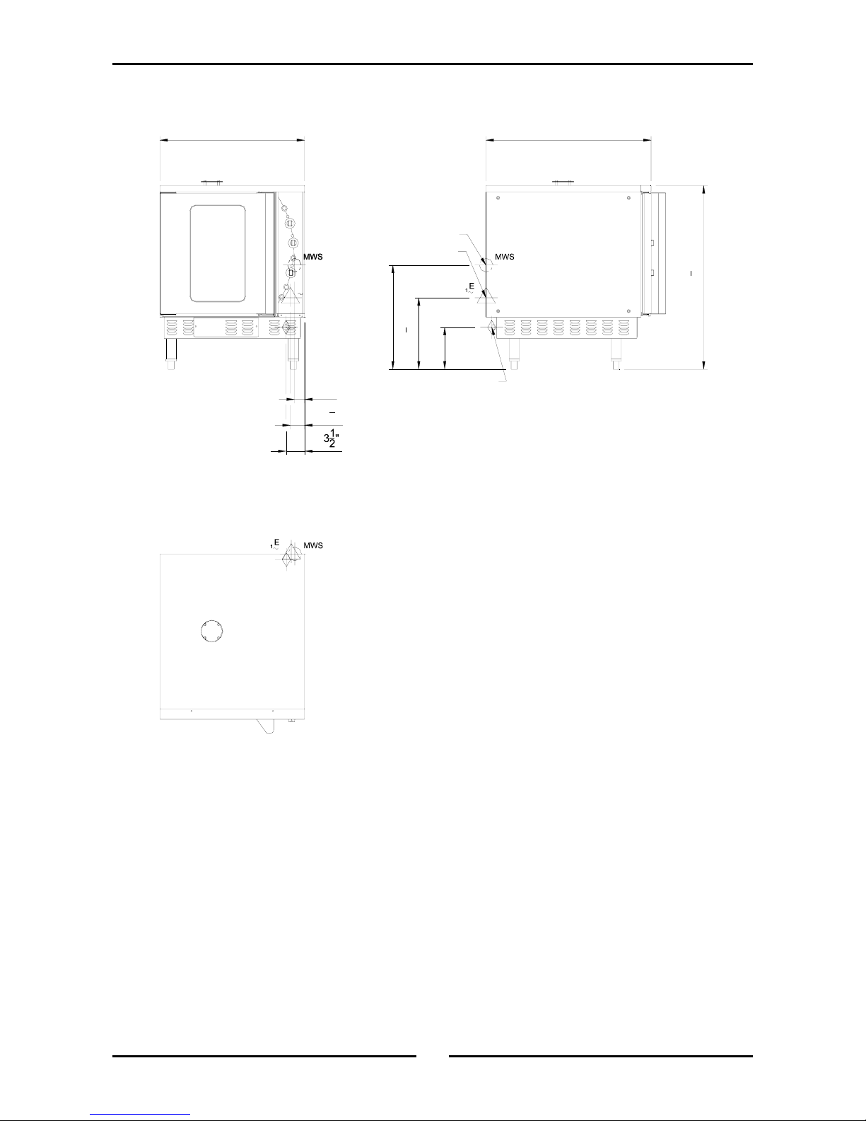
Specifications
13
3
4
"
20"
2"
2
3
4
"
GAS
28"
EE
GAS
11
35
1
2
"
8"
32"
GAS
WATER ENTRY
ELECTRICAL ENTRY
GAS ENTRY
Plan
Side
Front
BACO32G Oven
Page 8
4
Installation
Installation Requirements
This appliance must be installed in accordance with National installation codes and in addition, in
accordance with relevant National / Local codes covering gas, electrical and fire safety.
UNITED STATES: ANSI 223.1 (Latest edition) National Gas Fuel Code.
CANADA: CAN/CGA - B149, Installation Codes for Gas Burning Appliances and Equipment.
Installations must be carried out by authorised persons only. Failure to install equipment to relevant
codes and manufacturers specifications in this section will void warranty.
The oven and its individual shutoff valve must be disconnected from gas supply piping system during
any pressure testing of that system at test pressures in excess of 0.5 psi (3.45 kPa / 34.5 mbar).
This oven must be electrically grounded in accordance with local codes.
Before Connection to Power and Gas Supplies
• Remove all packaging.
• Check equipment and parts for damage. Report any damage immediately to the carrier and
distributor.
• Remove protective plastic coating from the side panels.
• Check that the following parts have been supplied with your oven:
4 x Leg assembly.
4 x Oven racks.
1 x Water inlet elbow (c/w washer).
• Report any deficiencies to the distributor who supplied the oven.
• Fit the legs to the oven.
• Check that the available power and gas supply is correct to that shown on the rating plate located on
the right-hand side panel.
Supply Requirements
It is most important that this oven is installed correctly and that operation is correct
before use.
Installation shall comply with local electrical, gas, health and safety requirements.
Natural Gas LPG
Input Rating (N.H.G.C.).
35 MJ/hr (33,000 Btu/hr). 35 MJ/hr (33,000 Btu/hr).
Injector Size.
Drill no. 51 (Ø2.70 mm). Drill no. 36 (Ø1.70 mm).
Manifold Pressure.
1.13 kPa (4½” w.c.). 2.75 kPa (11” w.c.).
Gas Connection.
½” NPT Female.
Electrical Connection.
110 Volts AC, 60Hz, 2.0A, 0.24kW, 1P+N+E.
Cold Water Connection.
¾” G.H.T. (80psi maximum pressure).
Page 9

5
Installation
Location
• This oven must be installed in an area of adequate air supply. To ensure correct ventilation for the
motor and controls the following minimum installation clearances are to be adhered to:
• This oven must be fitted on supplied legs in all installations.
• Position the oven in its working position.
• Use a spirit level to ensure oven is level from side to side and front to back. (If this is not carried
out, uneven cooking could occur). The legs used with bench / floor mounting or provided with
stands are adjustable and will require adjusting in levelling the unit.
• The unit should be positioned such that the operating panel and oven shelves are easily reachable
for loading and unloading.
• Adequate ventilation is essential. DO NOT obstruct the air flow around the ventilation slots.
Gas Connection
• A ½" N.P.T female connection is provided at the bottom rear of the oven.
• A restraint chain anchor has been provided above the gas connection point for fitting a restraint
chain when a flexible gas line is fitted.
• It is important that adequately sized piping run directly to the connection joint on the oven with as
few tees and elbows as possible to give maximum supply volume.
• A suitable jointing compound which resists the break down action of LPG must be used on every gas
connection.
• Check all connections for leakages.
• Check the appliance name plate at oven front right hand corner for correct injector size and
operating pressure for the gas being installed before operation.
• The appliance combination gas valve is fitted with an internal regulator for adjusting the operating
pressure. To access, remove appropriately marked side service panel from bottom right side of
oven. Unscrew and remove regulator cap from gas valve. Adjust the regulator to achieve stated
pressure.
NOTE: Pressure test points are located behind this side service panel also at bottom
right side of oven.
Electrical Connection
This oven is fitted with an approved power supply cord via an electrical junction box at the right hand
rear of the unit. Should changing of the cord be necessary then follow the instructions shown below:
• Remove right hand side panel to allow access to the terminal block and strain relief cable clamp.
• The cable can be fitted through the small grommet and held by the cable clamp.
• Connect cable to the terminals as marked.
• Refit cover panel.
Important:
THE VENT LOCATED ON THE OVEN TOP MUST NEVER BE OBSTRUCTED.
Top 200 mm / 8” (or 600mm / 24” from a combustible surface).
Rear 75 mm / 3”
Left-hand side 75 mm / 3”
Right-hand side 75 mm / 3” (Fixed installations require at least 500mm (20”) clearance at
the right hand side for service accessibility).
Page 10

6
Installation
Water Connection - Optional (Not Required for Main Oven Operation)
• If the manual addition of water into the oven for humidification or steaming effect on baked product
is required, the unit’s water connection can be used.
• A cold water supply should be fitted to the water inlet (¾” G.H.T. hose connection) which is located
on the rear of the right hand side of the unit.
• Alternately, a connection elbow and sealing washer is supplied with this unit for direct connection of
a ½” ID hose, and is recommended for easy installation and service.
• Connect water supply - Max inlet pressure 80psi / 550kPa.
• Turn on water supply to check for leaks.
Before Use
• Operate the oven for about 1 hour at 400°F (200°C) to remove any fumes or odours which may be
present.
Lighting Instructions
• Set the thermostat temperature.
• Automatic ignition will light the burner.
• If not, turn the thermostat off, and wait 5 minutes before relighting.
• The burner will cycle on / off to maintain the set temperature.
• Turn the thermostat off to shut-down the burner.
NOTE: If the burner is not cycling to maintain temperature, the ignition system may have
locked out. To reset the ignition system, turn the thermostat to the ‘Off’ position.
Wait 5 minutes before relighting. If the flame is lost during operation the ignition system will try three times to re-establish the flame with a 30 second delay between each
try, before going into lockout
.
Reversing the Door
If desired, a left hand hinged oven door can be changed to a right hand hinged door (or vice versa).
• While supporting the door, undo the door hinges from the oven. Remove the door.
• The bottom right door catch plate should now be transferred to the top left of the oven, and the top
right door catch plate transferred to the bottom left of the oven.
• Secure the door hinges and oven door to the right hand side of the oven door opening.
• If alignment of the door is necessary, the five screws along the bottom of the oven can be loosened,
and the door moved a small amount to ensure that it is square with the oven. Tighten the screws
when the correct door position is attained.
• If necessary the roller catches can be removed from the door (after removing handle on stainless
steel doors) to adjust height settings for correction of door catch operation.
Important:
MAXIMUM INLET WATER PRESSURE IS 550 kPa / 80 psi.
Important:
THE FOLLOWING PROCEDURE SHOULD ONLY BE PERFORMED BY A QUALIFIED
SERVICE PERSON.
Page 11

7
Installation
Type-B Vent - Optional (Part No. 018832)
(Not required for Main Oven operation)
Removal of Standard Flue Diverter
• Unscrew and remove the four screws fastening the diverter plate to oven (Figure A).
• Discard flue diverter and the four spacers, retain the four screws.
Fitting of the New Flue Vent
• Using the four existing screws, fasten the B-type vent to oven flue (Figure B).
• The spigot of the B-type vent is designed for connection of a Ø4” (100mm) vent.
Figure A. Figure B.
The State of MA requires that when using the ‘B’ Vent Kit, the unit must be interlocked
into an approved hood system or direct flued externally, in compliance with local gas
and plumbing codes.
Page 12

8
Operation
Operation Guide
Power
Depress to switch power ‘On’ or ‘Off’ (switch
illuminates when power is ‘On’).
Thermostat
Temperature range 120 - 600°F.
Indicator illuminates when the burner is cycling
‘On’ to maintain set temperature.
Bake Timer
1 Hour bake timer.
(Indicator illuminates when ‘Time Up’ (0) reached,
and buzzer sounds).
Roast ‘n’ Hold
Depress switch to activate ‘Roast-n-Hold’ function.
(Switch illuminates when ‘On’).
Roast Timer
3 Hour roast timer.
(Indicator illuminates when ‘Time Up’ (0) reached,
and product is held at 165°F).
Steam Switch
Push switch to activate water injection. (Water
injects into oven while button is depressed).
Light Switch
Push switch to activate lights.
(Lights illuminate while button is latched in the
‘Down’ position).
Description
of
Controls
Important:
Ensure that a clearance of 2” (50mm) from the oven ceiling is maintained when placing product on the top
shelf. This ensures correct operation of the oven.
Page 13

9
Operation
Baking
1. Turn power ‘On’.
Power switch illuminates when it is depressed and latched in the ‘Down’ position.
2. Set thermostat to the desired temperature.
The heating indicator light will illuminate whenever the burner is cycling ‘On’ to maintain the
set temperature.
NOTE: If the burner is not cycling to maintain temperature the ignition system has
locked out. To reset turn the thermostat to the ‘Off’ position.
If the flame is lost during operation the ignition system will try three times to
re-establish the flame with a 30 second delay between each try, before going
into lockout.
3. Load oven.
Once the oven is up to temperature, open the oven door and load the oven with product.
Avoid delays in loading the oven with the door open as this will delay the oven’s temperature
recovery.
NOTE: The oven lights will illuminate when the door is opened.
4. Set bake timer to desired time.
To set timer, turn knob clockwise to the required time. At any stage, the time can be adjusted
in either direction.
For settings less than 10 minutes, first set to greater setting, then turn down to the required
time period.
NOTE: This 60 minute timer is completely independent of the oven control.
5. Water injection.
To steam the oven while baking, push the steam switch on the control panel. We
recommend a 2-15 second injection period, according to product need, for this oven.
Keep steam switch depressed for required steam period.
6. Light.
To view the product while baking, depress the light switch on the control panel. The lights
will stay ‘On’ while the switch is latched in the ‘Down’ position.
7. Time up.
When the timer reaches 0 minutes the buzzer sounds and the indicator illuminates.
To cancel the buzzer turn the timer to the ‘Off’ position.
8. Unload oven.
Open the oven door and unload the oven.
NOTE: The oven lights will illuminate when the door is opened.
Page 14

10
Operation
Roast ‘n’ Hold
1. Turn power ‘On’.
Power switch illuminates when it is depressed and latched in the ‘Down’ position.
2. Set thermostat to desired temperature.
The heating indicator light will illuminate whenever the burner is cycling ‘On’ to maintain the
set temperature.
NOTE: If the burner is not cycling to maintain temperature, the ignition system has
locked out. To reset turn the thermostat to the ‘Off’ position.
If the flame is lost during operation the ignition system will try three times to
re-establish the flame with a 30 second delay between each try, before going
into lockout.
3. Load oven.
Once the oven is up to temperature, open the door and load the oven with product. Avoid
delays in loading the oven with the door open as this will extend oven temperature recovery.
NOTE: The oven lights will illuminate when the door is opened.
4. Set roast timer to the desired time.
This 3 hour timer is electrically driven and is set by turning the timer knob in either direction
to the required time. The timer can be set when convenient, but will not start working until
the oven control is set and the ‘Roast-n-Hold’ switch is depressed (switch illuminated).
5. Depress roast switch.
Depress the ‘Roast-n-Hold’ switch. The switch will illuminate and the timer will begin to count
down.
6. Water injection.
To steam the oven while roasting, push the steam switch on the control panel. We
recommend a 2-15 second injection period, according to product need, for this oven.
Keep the switch depressed for required steam period.
7. Light.
To view the product while roasting, depress the light switch on the control panel. The lights
will stay ‘On’ while the switch is latched in the ‘Down’ position.
8. Hold.
When the timer reaches the ‘Hold’ position, the main oven thermostat is turned ‘Off’ and a
pre-set hold thermostat located behind the control panel will control the oven to keep the food
warm at serving temperature as long as required until the ‘Roast-n-Hold’ switch is turned ‘Off’.
NOTE: The hold light will illuminate when the timer reaches ‘Hold’ until the ‘Roast-n-
Hold’ switch is turned ‘Off’. The ‘Hold’ light may come on briefly when the
‘Roast-n-Hold’ control is first switched ‘On’ until the oven heats up beyond the
pre-set holding temperature.
Page 15

11
Operation
Oven Racks
The oven is supplied with four general purpose oven racks. These racks incorporate two important safety
features:
• Self Supporting: When fitted, the oven racks are self supporting and will not drop or angle down
when the racks are withdrawn during operation, when loading and unloading products on racks or
when attending to the product being cooked during it’s cook cycle.
• Auto Supporting: The oven rack supports incorporate a special retaining tab which provides a
positive stop to each oven rack and stops it’s inadvertent removal during normal operation.
To fit the oven racks follow the steps shown in the diagram below.
To remove the oven racks, carry out the procedure in reverse.
1
2
3
4
5
1. Fit the oven rack, positioning the rack back stop on top of the rack runner.
2. Slide the rack along the runner and ensure that the front stop is under the rack runner.
3. Slide the rack to the rear of the oven.
4. Allow the rack back stop to drop below the rack runner.
5. The rack can now be pulled forward and loaded as required.
Page 16

12
Cooking Guide
This Belshaw Adamatic Oven will cook a greater quantity of food faster, at a lower temperature and more
evenly than an ordinary oven. As many excellent recipe books are published, it is not our intention to list
recipes, but to provide a temperature and time chart as a guide.
Baking
Select a temperature of about 35-55°F lower than in a conventional oven and preheat oven until the
heating indicator light goes out. The oven has now reached the desired temperature and trays of
food may be placed in the oven. The oven will take four American trays (26" x 18") or eight
American half trays (18" x 13").
Use the racks supplied if American baking trays are not available.
FOOD TEMP °F TIME
Sponges 330 10-12 mins
Small Cakes 330 8-12 mins
Butter Cakes 320 35 mins
Fruit Loaf 300 40-50 mins
Macaroons 320 15-20 mins
Biscuits 285 12-20 mins
Shortbread 265 15-20 mins
Scones 390 10-12 mins
Madeira 330 35-50 mins
Bread 350 25-35 mins
Plain Fruit Cake 330 1-1½ hrs
Rich Fruit Cake 265 2-3 hrs
Gingerbread 285 35-50 mins
Baked Custard 265 50 mins
Souffle 330 25 mins
Rice Pudding 265 2-3 hrs
Pastry;
Puff 430 8-12 mins
Short 350 8-12 mins
Flakey 400 8-12 mins
Jam 365 12-20 mins
Fruit 365 35 mins
Bake-Off
Frozen product (yeast, breads or butter based pastries) is placed on baking trays and put into a
refrigerator overnight to thaw. After proofing, the trays of breads or pastries are baked in this oven.
Oven temperature for yeast based products should be 340-355°F.
Oven temperature for butter based products should be 320-330°F.
A full load will bake in 20-25 minutes.
Page 17

13
Cooking Guide
Roasting
Set the oven temperature to 300-320°F. The hot air circulating in the oven reduces moisture loss
and shrinkage. Roasting times are reduced by approximately 10 minutes per lb.
MEAT TIME per lb
Beef - Rare 15-20 min
Beef - Medium 20-25 min
Beef - Well Done 25-30 min
Veal 25-35 min
Lamb 15-20 min
Duck 25 min
Goose 25 min
Turkey 15-20 min
Chicken
- under 2 lb
- over 2 lb
25-30 min
20-25 min
Roast-n-Hold
This system will automatically cook food for a set time, then hold the oven at a preset temperature
indefinitely to maintain food at a serving temperature after cooking has been completed.
When the oven has reached the set temperature, place food in the oven, set roast cooking time and
depress the ‘Roast-n-Hold’ button. The ‘Hold’ indicator will illuminate when cooking is complete.
To return to normal operation, push the ‘Roast-n-Hold’ switch again (switch will cease illuminating).
Page 18

14
Cleaning
Cleaning Guidelines
Exterior
Clean with a good quality stainless steel cleaning compound. Harsh abrasive cleaners may damage
the surface.
Interior
Ensure that the oven chamber is cool. Do not use wire brushes, steel wool or other abrasive
materials. Clean the oven regularly with a good quality oven cleaner. Take care not to damage the
fan or the tube at the right side of the oven which controls the thermostat.
Oven Racks
To remove, follow instructions given in the ‘Operation’ section.
Side Racks
To remove, lift front top to disengage and slide rack forward. To replace, slide top rear slot in rack
onto rear stud, then engage front keyhole on front stud.
Lamp Glass
To remove lamp glasses, unscrew anti-clockwise. To replace, screw in clockwise, but do not over
tighten. Ensure that the silk gasket is fitted before replacing the lamp glass.
Oven Seals
To remove, hold at their centre point and pull forward until they unclip. Remove side seals first, then
top and bottom. The seals may be washed in the sink, but take care not to cut or damage seals.
To replace seals, have the lip facing the oven opening. Fit the top and bottom seals first, then the
side seals.
Oven Door Glass
Clean with conventional glass cleaners.
Venting
Regularly check that the oven flue tube is free of obstruction. The flue tube must NEVER be
covered.
Lubrication
No lubrication is required by the user as components are self-lubricating.
It is recommended that the door catches are lubricated occasionally with a light coating of grease to
provide smooth operation.
C
AUTION
:
Always turn off the electrical supply at the mains supply before cleaning.
This appliance is not water proof.
Do not
use water jet spray to clean interior or exterior of this appliance.
Page 19

15
Fault Finding
Fault Possible Cause Remedy
The oven does not operate /
start.
The mains isolating switch on the
wall, circuit breaker or fuses are
‘Off’ at the power board.
The power switch on the oven is
‘Off’.
Turn ‘On’.
Depress the switch. Switch will
illuminate.
Burner will not ignite. Isolating valve on the oven is
turned ‘Off’.
No gas supply to unit.
Turn ‘On’.
Check gas supply.
Bake timer does not time down. Bake timer not set correctly. For settings less than 10 minutes,
first set to greater setting then turn
back to desired setting.
Roast timer does not time down. Roast-n-Hold button not
depressed.
Depress Roast-n-Hold button.
(Roast timer only operates when
Roast function is selected).
Oven light not illuminating. Blown bulb. Replace bulb.
No water injection / steam. Water not turned ‘On’. Turn water ‘On’ at water supply.
This section provides an easy reference guide to the more common problems that may occur during the
operation of your equipment. The fault finding guide in this section is intended to help you correct, or at
least accurately diagnose problems with your equipment.
Although this section covers the most common problems reported, you may encounter a problem not
covered in this section. In such instances, please contact your local authorised service agent who will
make every effort to help you identify and resolve the problem. Please note that the service agent will require the following information:-
• The Model Trade Name and the Serial Number of the Appliance. (Both can be found on
the Technical Data Plate located on the appliance).
Page 20

16
Wiring Schematic
BACO32G Circuit Schematic
V2
S1
GND
YELLOW
BLUE
TH
V1
BLACK
WHITE
SPARK
LIGHTS
TIME
UP
1
3
4
LIGHTSWATER
2
1
3
NC
M'SWITCH
DOOR
C
T'STAT
4
5
M
2
1
3Hr TIMER
HEATING
6
3
135
7
HOLD
4
HOLD
42
8
6
2
HOLD
3
1
2
THERMOSTAT
HOLD
1
2
1
4
3
2
1
IGNITION
BOX
2
1
2
1
NO
1Hr TIMER
GAS SOLENOIDS
1/2" NPT MALE
10mm ID HOSE
GAS
(3/8 inch)
WATER
GAS REGULATOR
CONNECTIONS
EARTH/GROUND
ELECTRICAL
(GREEN/YELLOW)
(RED)
(BLACK)
NEUTRAL
BUZZER
B
POWER
WATER
TRANSFORMER
SENSOR
WATER SOLENOID
INJECTOR
Page 21

17
Wiring Schematic
BACO32G Wiring Diagram
BLUE
110V
NEUTRAL
208V
YELLOW
BLACK
RED
WHITE
TRANSFORMER
31
32
33
240V
ORANGE
20 54
NEUTRAL
PHASE
EARTH
FLAME SENSER
34
13
40
39
51
29
35
35 29
48
49
36
33
3
53
31
50
51
32
N
1
1
N
19
19
18
37
36
37
38
38
39
16
52
HOLD
T/STAT
42
7
17
LIGHTS
SWITCH
1
2
CONTROL PANEL
EARTH TAG
47
DOOR
MICROSW
COM
ROAST &
HOLD
23
4
16
6
STEAM
SWITCH
7
1
2
24 25
5
1
2
3
6
28
8
3hr TIMER
27
11
1 3
46
28
27 20
21
21
12
8
EARTH STUD
18
17
NO
NC
49
13
48
50
26
12
26
BAKE TIMER
INDICATOR
5
6
5
1
4
2
9
3
44
45
BAKE TIMER
23 24
2
4
25
1
3
RELAY
6
11 45
78
5
43
10
42
T/STAT
22
2
1
21
BUZZER
9
10
T/STAT INDICATOR
40
4
22
42
41
POWER SWITCH
1
2
3
4
3
41
44
43
WATER
SOLENOID
P
N
IGNITION
ELECTRODES
1
V2
GND
S1
V1
TH
GAS
SOLENOIDS
30
IGNITION BOX
TERMINAL
BLOCK
FAN MOTOR
Page 22

18
Replacement Parts List
Replacement Parts List
When ordering spare parts, please quote the part number and the description as listed below. If the part
required is not listed below, request the part by description and quote model number and serial number
which is shown on the rating plate.
IMPORTANT:
Only genuine authorized replacement parts should be used for the servicing and
repair of this appliance. The instructions supplied with the parts should be followed
when replacing components.
For further information and servicing instructions, contact your nearest authorized
service branch (contact details are as shown on the reverse of the front cover of this
manual).
Main Assembly Parts List- BACO32G
Pos Part No. Description
1 024683 SIDE COVER PANEL.
2 ---------- GEAR PLATE (Refer Page 23).
3 015821 FAN MOTOR (110V) – c/w Heat
Insulation Disc.
4 014694 MOTOR MOUNTING PLATE.
5 023216 OVEN LIGHT ASSEMBLY E26
(110V).
003434 SILK GASKET.
003002 LIGHT GLASS.
6 024717 BAFFLE LOCATING BRACKET.
7 010761 GROMMET ø1½" RUBBER.
8 004950 SIDE GAS SERVICE ACCESS PANEL.
9 024689 SIDE COVER MOUNTING BRACKET.
10 024852 HEAT DEFLECTOR.
11 019239 SNAP BUSH 19mm.
12 021057 SPRAY NOZZLE.
13 024702 WATER SOLENOID MOUNTING
BRACKET.
14 021619 REAR SERVICE PANEL.
15 021617 WATER SOLENOID (110V).
16 020869 CONNECTOR
3
/8”F x ¼”COMP.
17 021058 WATER TUBE / ELBOW ASSEMBLY.
18 013215 BACKNUT.
19 014031 OVEN BAFFLE STUD.
20 004925 OVEN LINER ENAMELLED.
21 015598 FAN.
22 016245 HOOD SPACER.
23 016241 VENT HOOD PLATE.
24 041401 SCREW M6 x 35 ST/ST.
25 041405 SCREW ½” x
3
/16”.
26 003397 SPACER.
27 024847 LINTEL ST/ST.
28 024672 LINTEL SUPPORT.
29 024785 TOP/BOTTOM DOOR SEAL.
30 024784 LEFT/RIGHT DOOR SEAL.
31 013974 PHIAL GUARD.
32 024803 ROLLER STRIKE TOP.
33 024804 ROLLER STRIKE BOTTOM.
34 004949 INJECTOR ACCESS PANEL
ENAMELLED.
35 015656 FAN BAFFLE RH.
36 015575 SIDE RACK LH.
Pos Part No. Description
37 020082 TOP HINGE (Assembled with
Bush).
017905 BUSH.
38 ---------- DOOR ASSEMBLY (Refer Page 24).
39 020083 BOTTOM HINGE (Assembled with
Bush).
017905 BUSH.
40 004397 RADIATION BAFFLE ENAMELLED.
41 ---------- CONTROL PANEL ASSEMBLY (Refer
Page 21).
42 021638 PIN CIRCLIP.
43 013610 BUSH.
44 044210 SPIRE CLIP.
45 021637 MICROSWITCH BUTTON.
46 024791 MICROSWITCH ROD.
47 017929 DAMPER ROD CLIP.
48 024802 MICROSWITCH.
49 013977 INSULATOR.
50 024584 MICROSWITCH BRACKET.
51 230578 LEG 6”.
230577 LEG PLATE (Not Illustrated).
52 021526 WATER INLET ELBOW.
021527 WATER INLET WASHER.
Page 23

19
Replacement Parts List
Main Assembly - BACO32G
Page 24

20
Replacement Parts List
Control Panel Assembly - BACO32G
9
8
4 6
2
7
4 6
45
3
10
14 13 1112
1
17
16
15
1918 20 21
Pos Part No. Description
1 024805 CONTROL PANEL ST/ST.
2 233233 OVERLAY BELSHAW BACO32G °F.
3 021514 POWER SWITCH.
4 023857 INDICATOR LIGHT.
5 021472 THERMOSTAT KNOB.
6 020823 TIMER KNOB.
7 021515 ROAST N HOLD SWITCH.
8 021474 STEAM SWITCH.
9 024773 LIGHT SWITCH.
10 024694 CONTROL PANEL HOOK.
11 018223 HOLD THERMOSTAT.
12 021538 HOLD STAT BRACKET.
13 018209 HOLD STAT LABEL.
14 018224 HOLD STAT KNOB.
15 021442 TIMER MOUNTING PANEL.
16 015823 3 HOUR TIMER.
17 021535 RELAY.
18 015822 BUZZER.
19 024703 BUZZER / RELAY BRACKET.
20 011760 60 MINUTE TIMER.
21 024774 THERMOSTAT 50-320°C.
Page 25

21
Replacement Parts List
Gas Assembly - BACO32G
Pos Part No. Description
1 004952 BURNER.
2 032280 INJECTOR 2.80mm.
032180 INJECTOR 1.80mm.
3 SA1595 INJECTOR MOUNTING BRACKET ASSEMBLY.
4 024156 FLEXTUBE 12” x
3
/8” OD.
5 024787 SADDLE 40mm.
6 024765 GAS SOLENOID BRACKET.
7 015313 MACK UNION.
8 015626 GAS SOLENOID.
9 019371 PRESSURE TEST POINT.
10 015311 PLUG.
11 015314 ADAPTOR ½”NPT x ½”BSP.
12 015310 BALL VALVE
3
/8” BSP.
13 015176 ELBOW ½” BSP.
14 025071 FLAME SENSOR WORKED.
15 024127 SPARK ELECTRODES.
16 025072 ELECTRODE MTG BRACKET.
17 024105 IGNITION ELECTRODE BRACKET.
18 SA1530 IGNITION ELECTRODE COMPLETE ASSEMBLY.
6
5
1514
16 17
1 2 3 4
7
9
10
8 12 9
13
11
18
Page 26

22
Replacement Parts List
Gear Plate Assembly - BACO32G
Pos Part No. Description
1 024853 GEAR TRAY.
2 002441 INSULATOR.
3 002138 CABLE CLAMP.
4 013586 MAIN TERMINAL BLOCK.
6 023024 IGNITION BOX FENWAL.
7 024851 TRANSFORMER.
7
Page 27

23
Replacement Parts List
Door Assembly - BACO32G
Pos Part No. Description
1 024809 ROLLER CATCH ASSEMBLY.
2 020083 BOTTOM HINGE ASSEMBLY.
3 024605 GLASS CLAMP ANGLE.
4 023063 DOOR WINDOW GLASS.
5 090201 GLASS SEAL EXTRUSION (1.44m).
6 024845 DOOR OUTER PANEL.
7 090201 GLASS SEAL EXTRUSION (1.44m).
8 020082 TOP HINGE ASSEMBLY.
9 004957 DOOR INNER (ENAMELLED).
10 ---------- INSULATION.
11 024713 DOOR HANDLE.
SA1587 ST/ST DOOR COMPLETE.
Page 28

 Loading...