


1080
MODEL
Abrusive
ABRASIVE BELT GRINDER OPERATING
TOSO
INSTRUCTIONS
AND PARTS LIST
Belt
Grinder
SPDCIFICATIONS:
OVERALL SIZE:
WORK TABLE
TABLE TILT ANGLLS:
MOTOR:
STANDABD
SPECIAL
ADJUSTABLE IDLER
SELF-ALIGNING UPPER WHEEL - AUTOMATICALLY ALIGNS
PRECISION
AUTOMATIC
QUICK
SEALED BALL BEARINGS
BELT
SURFACE:
FEATURES
_
ARM
GROUND TABLE
BELT TENSION
CHANGE
_
USES
IN
DRIVE WHEELS
USED
EASILY
_
FOR
BELT SUPPORT ON
LOCKED AT ANY ANGLE
INSURES LONG
I" X M"
ABRASIVE BELTS
AND
EVEN
PRECISION
BELT
8.5 INCHES WIDE
INCHES
I4.O
INCHES
22.0
INCHES
8.5
7.0 INCHES DEEP
20" BACK
FORWARD MAXIMUM
70"
I/4 HORSEPOWER
I75O
RPM
IIOV,
BELT WITH LOWER
_
ASSURES EVEN
WEAR
60 CYCLE AC
INSIDE WORK
DEEP
HIGH
WIDE
MAXIMUM
WHEEL
GRINDING
IIIACHINDRY
CO
liilol
Equitable
Bd.,
Bor 593
o
f,ansas Gity,-to. 6f1{1
1dffia

INDEX
INTRODUCTION
SAFETY RECOMMENDATIONS
GLOSSARY
PARTS
PARTS
r0B3
rOB4 MOTOR MOUNT
ASSEMBLY
BELT INSTALLATION
BELT
LIST
ITLUSTRAT1ON
(FLOOR
ALIGNMENT
ABRASIVE
CIRCUTAR
TOOTH
BACK
SHAPING
K)INTS .
BEVELING
SAW
TERMS
OF
STAND)
INSTRUCTIONS FOR IO8O BELT
BELTS
SAW SHARPENING
TEETH
PARTS
.
.
ON THE TOBO
rrST.
ON
GRINDER
TO8O
THE
BELT
BELT GRINDER .
AND TO83 FLOOR
GRINDER
STAND .
I
2
3
4
5
6
6
7
I
9
l0
tl
t2
r3
t4
SCISSORS
PINKING
SHEARS .
CHISELS.
SCREWDRIVER
ROTARY
AXES, HATCHETS,
GARDEN
HEDGE
HEDGE
SETNNG
SHARPENING
TAWNMOWER
TOOLS
TRIMMERS
SHEARS
UP FOR INSIDE
GENERAL
.
KNIVES USING THE
SHOP TIPS
BLADES
AND
CLEAVER WEDGES.
GRINDING .
#27I
KNIFE
SHARPENING FIXTURE
r6
t7
l8
r9
r9
2l
22
23
2/L
25
.
%
27
I
'1
l
l
l

INTRODUCTION
Belsaw
The
work.
Designed
artd
The
metals.
The
continuous
shipperin
and check
or
It will
clean
Model 1080
It's perfect
1080
missing
Abrasive
sharpen
for quick
Belt
scissors,
easy sharpening,
of burrs.
also be used
can
for
those
abrasive
use.
good condition.
your
parts
belt
has been
It
equipment carefully.
and
Grinder
will
mower
for cleaning,
inside
grinder
is
carefully
receiving
Upon
immediately
just
sharpen
blades,
belt
the
that
edges
heavyduty,
a
tested"
ginder
about
knives,
sanding,
are hard
rugged
inspected
your equipment,
Using the part
write the Customer
anything
chisels,
not
does
carving, polishing
to sharpen using
grinder,
and packed at our
inspect the shipping cartons
numbers
Services
in your shop,
drills,
burn
built
and description, make a
teeth
saw
your
-
and
other methods.
to
Department, Belsaw
and with
in less
virtually
-
finished work
shaping
industrial
time
all cutting
is
smooth,
wood,
of
standards
plastic,
for years
factory and was delivered
for
list
signs
any
of
of
Machinery
less
edges.
sharp,
and
of
to the
damage
damaged
Co.
We will
then
furnish
necessary
the
for returning the equipment
Your new Belsaw
parts. If
any
is guaranteed
part
should
need
MACHINDRY GO
repair parts and instructions
to our
for one
replacement,
factory
year from date of
for
exchange.
write our Customer Service
6801 Equitable
for filing dar.naSe
purchase against
Delnrhent.
Bor
Rd.,
claim,
or insfructions
faulty workmanship or defective
593
o
Kansas Gi$,
ltlo. 64141
6ffim
Pagc
1

SAFETY
RECOMMENDATIONS
1.
Before
operation
the
using
your
and
Belsaw
new
applications
the
gnnder
you
read
can
instruction
your
perform'
manual
carefully'
2.Alwaysmakesureyourmotorswitchisoffwhenplugginginpowercord.
operation'
3.
4.
5.
6.
Always
Remove
U.pLrg
sure
Be
wear
rings,
power
remove
to
safety
watches
cord
gtasses
and
before
adjusting
any
face
or
ties.
making
shield
Do
wrenches
when
wear
not
adjustments
the
loose-fitting
or
tools
or
grinder
changing
before
is in
clothing'
belts'
starting
equipment'
From
you'll
it
learn
z.
g.
g.
Keep
you
so
Never
Make
this
hands
don,t
operate
sure
manual
away
have
your
the
fron
to
belt
belt
abrasive
overreach
grinder
tracks
ProPeily
surface.
do
to
damp
a
in
the
on
Maintain
work.
wet
or
the
Pulley.'
control
proper
Keep
location.
work
your
of
footing
work
The
Adi'sment
times-
at'all
balance
and
drould
area
procedures
Position
all times'
at
well
be
included
are
yourself
lighted'
later
in
P*2
i
(
\

BEVEL
The
the
angle
purpose
GTOSSARY
a cutting
on
tool or
of the
TERMS
OF
surface
blade.
of a tool or
blade. A"d"
varies
depending on
I
CANNELL
EDGE
Rolled
objects.
edge on
digg"g tools
to reduce
nicking
rocks or
by
other
sharp
I
each tooth.
CHALK-LINE
BACK.CLEARANCE
FINISH.SHARPENING
.
FLAT-GRIND .
FREDHAND GRINDING
GUMMING
HOLLOW.GRIND
.
drawn
Line
basic shape
Refers
tooth
being
Achral
Refers
also
Grinding
Refers
sawblade.
Grinding
chisels
to
must
cut.
sharpening
to grinding
refers to grinding
a cutting surface
grinding,
to
the
similar
and
on wood table
of
beveling
or
face
the
the cutting
shaping
srrface
tools.
lower
b€ ground
cutting
guide
for
as a
back of tooth
the
than the tooth
of the
teeth on
of tooth on circular
surface
without use of
or increasing the depth of the gullet on
with
a slightly eoncave
sharpening
even
on circular
a sawblade.
flat as
a
guide.
point
blades without
opposed
of
sawblades.
it clears the
so
Back of
wood
angle. Can
to hollow grinding.
a circular
edge. Can be used
on
and
HONING
HOOK
ANGLE
.
Cleaning
A"d"
up
between a line
tooth point
JOINTING
Sometimes
It brings the blades to
LOADING
*
SETTING
SHAPING
SHINER
.
Befers
Describes
sawed eo that
Restoring origind
Flat spot
to build+p on abrasive
on point
resharpening
drawn
to
the center
cdled rounding,
a tme cutting circle
a
method of
the blade
ehape of teeth on blades or
of
circular
to a very fine edge.
along
hole.
dhe first step
belts, primarily from wood
providing
does not
bind in the cut.
sawblades
face
the
in
with every
clearance
left after
a
of
sawblade
resharpening circular
to a
line from
tooth the same
duminum.
or
in the cut of material
tools.
jointing.
the
sawblades.
length.
being
he. 3
t-
---"

l
PART
BC'.1
BG.2
Be*3
BCF4
BG-6
BG7
Bc-8
Be'-9
Bc'.lO
BCr.11
BC-12
BG13
BG-14
BCr15
BC-16
Bcr.17
BG-194
BG-20
Be*22
BG-26
BG-27
8G.29
BC-30
BC*31
BG'33
BC*38
BG41
Bc*46
BG-52
BG55
BG60
BG-61
z-77
7-85
Z-LL4
z-r15
z-rL6
Z.LT?
z-Lt$
Z-LLg
z-t20
z-tzL
z-r22
2-124
z-t25
7-126
NUMBER
ABRASIVE
ORDER
Column
RightBase
Base
Left
Mounting
Front
Backstop,
Cover
Upper
Upper
Plate
Arm
Axle
Spring,
Lower
Adaptor,
Hinge
Idler
ldler
Idler
Table
Table
Lower
Lower
End
Upper
Ball
?
3"
Table
Oilite
Spring
5/8
,.v"'Belt
Upper
Ball
Pin
Pulley
Axle,
Axle,
Adjusting
Ball
hrlley
Cap,
Pulley
Bearing
V-Belt
V-Belt
Bracket
Bearing
Clip
I.D.
Idler Arm
hrlley
Idler
Abrasive
.
Nuts
Lower
Nut,
Table
Nut,
Adjusting
Table
Screws
Screw,
Upper
Adjusting
Cap
End
Idler
Nut,
Screw,
10-24x
Back
Idler
Stop
5/1L18
Screws,
Ipwer
Pulley
Pulley
Washer,
Belt
Screw
1/4
i
Table
PART
BY
DESCRIPTION
.
Channel
for 1"
Flat
.
.
.
Arm.
Bearing
Ball
..
Upper
Lower
Bracket
Bearing
Upper
Arm
....
(1/2"
Pivot
for Idler
.
Iower
with
Guard
Axle
Idler
Adjusting
Bracket
Arm StoP
Screw,
.
Arm
Arm
Socket
Screws
glA
So"k"t
Adjusting
PARTS
BELT
Belts
Axle
&
Bearing
and
....
hole
'
Oilite
(OPtional)
Bracket
UPPer
Screw,
Set
Set
IIST
GRINDER
NUMBER
....
&
Axle
motor,
for
hrlleY
Axle
Idler
(BeFf4
Screw
Screw
PulleY
Idler
Scnew
Bracket
MODET
AND
Adaptors
not shown
..
BC-il8)
and
Arm
Lower
for
1080
DESCRIPTION
(BG'12)
drawing)
on
Pultey
and.t
BELSAW
EOUITABLE
6301
firfiitrJ"ffi,,
NUMBER
""""'
V-Pulley
MACHINERY
ROAD
MrssouR!
REQUIRED
1
I
""'
1
1
1
1
....
CO.
64141
Page
4

l
oA.
c
H
a
z
c
()
Ed
Ff
frl
c0
H
a
E
o
c
co
o
Ff
14
a
o
=
z
o
Fr
&
F
U)
Ff
Fl
a
F
c
I
\
KT
Ti
EI
lEl
\
ni
lSl-a
LJ
EI
tl.'\ i
EZ,,b
N:
I
e
e
**lil
r13
o
e
r?
=6
=6
.A
5
i
i
FI
llel
I lntl
-u
-t
-f
a9
cl
=
j
i5
v,
.E
at
(rg
-
a
GD
€tt
rl':,
x
ct
o
E
E
ct
-cl
6g
=
=
E
lrl
e
c:t
G'
o
C)
)r
fr
rt
2
t{
H
*t
C)
d
E
lr
l}'
Ir
"il
I
'lrl
t-
@
I
t4
Page
a
a
]t
H
n
5
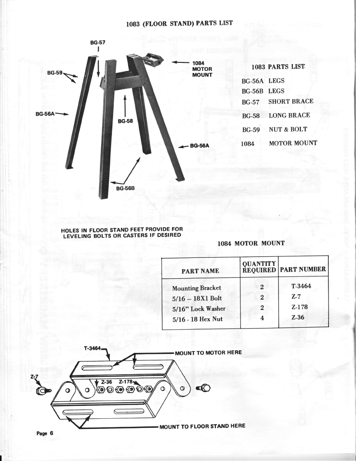
(FLOOR STAND)
1083
PARTS
LIST
8G.59
BG-56A-
HOLES
IN
LEVELING
FLOOR
BOLTS
STAND
CASTERS
OR
FEET
PROVIDE
IF DESIRED
FOR
-e
BG56A
IO83
BG.56A
BG-568
BG.s?
BG.58
BG-59
IO84
rO84 MOTOR
PARTS
LEGS
LEGS
SHORT
LONG
NUT &
MOTOR
MOUNT
LIST.
BRACE
BRACE
BOLT
MOUNT
Pas.6
Mounting
5116
5116"
5116
IIIOUNT
MOUNT
PART
lSXr
-
Lock
-
l8
FLq)R
TO
NAME
Bracket
Washer
Hex
TIIOTOR
TO
Boh
Nut
STATTID
HERE
HERE
QUANTITY
REQTIIRED
2
,
2
4
PART
T-346/!
z-7
z-t78
z-%
NUMBER

ASSEMBLY
GRINDER
INSTRUCTIONS
IO83
FLOOR
AND
FOR
IOSO
STAND
BELT
legs
l.
In an open
BG-568,
2. Using
Leg to
I
thcn connect
area, arrange
are on opposite
the
BG-59
Nuts and
a BG-56B
the two
Lcg,
assembled
four
the
corners.
Bolts
with BG-57
pair of legs
of the
The holes for
provided,
Short Brace.
floor stand
the
loosely assemble
Repeat
with
the
so
1084 Motor Mount
BG-58
each pair
of matching legs, BG-56A and
should
face
front and rear.
the
the floor stand connecting a BG-56A
the procedure
Long Braces.
with
the other pair of
legs;
t
Befort: tightening the
3.
nuts. The
two sections
floor stand. Do not attach motor
Floor
With the
4.
and
with
The ll4
5.
the
After aligning the
6.
wrench and screwdriver.
a
l0B3
attach with
a screwdriver
horsepower
motor
bracket,
four nuts
and
motor
hand-tight.
motor pulley
floor
of the
Stand
and bolts,
wrench.
stand,
put the l0B4
motor mount
until after
loosely
should
assembled, place
hand-tight.
be attached
with
Nlotor
should
llelt Grinder is attached
'l'hen,
to
the BG-30
pulley,
I\tount
swing
together using the shoulder
loosely.
Attach the motor mount to the
to the
the l0B0 Relt
tighten the
motor mount, tightening
the
tighten
Grinder on top
floor
the motor to the
floor
stand.
and belt grinder
stand
bolts and
of the
the nuts and bolts
motor mount
floor stand
in place
with
to
Place the
7.
proper belt tension.
the
B.
Once the
Table
screw to
2-126
the
so
that
will
angle.
hold
to
so that the table
The
9.
added
Screw and
beneath the
will
BG-27 Upp"r
V
belt over the
main
unit and
Bracket
Pivot
hold
the table
Table Adjusting
the BG-33 Table
for
turn
These
the table
optional
adjustment
screws should
in place,
angle can be
BG-61 Belt
by loosening the
positioned
be
placing
head of the screw.
Pulley.
the
BG-30
floor
and held
in place
Bracket Screws
Bracket
be tight
yet loose
Guard
Z-lI9
slot of
the
over
pulley
stand are assembled,
position with
in
on the BG-33 Table
Pivot
and
motor
of the table
enough
enough
moved easily.
may
be
End
Cap
the guard
The guard
top of the
the
pulley,
the
set
Bracket
letting the
BG-I9A
screw on the table.
Table
Pivot,
you can then adjust the tension
weight
can be
After
of the
placed
tightening
motor provide
BG-33
the
on
set
thc
of
OPTIONAL 8G.61 BELT GUARD
MOUNTED ON GRINDER
Page 7
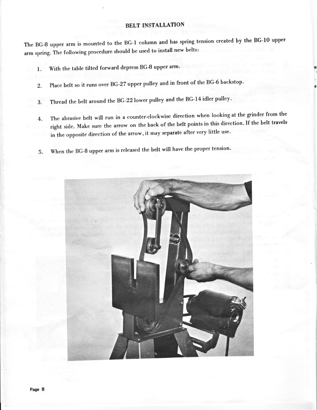
BELT
INSTATLATION
The
arm
BG-B
spring.
l.
2.
3.
4.
).
upper
The
the
With
Place
Thread
abrasive
The
right
inthe
when
is
arm
following
table
it
so
belt
belt
the
belt
Make
side.
opposite
BG-8
the
mounted
procedure
forward
tilted
over
runs
around
will
sure
direction
upper
the
to
should
BG-27
BG-22lower
the
in
run
arrow
the
of
is
arm
corumn
BG-r
used
be
depress
a
the
released
BG-B
the
on
arrow,
pulley
pulley
back
may
it
the
upper
counter-clockwise
and
install
to
upper
belt
has
arm'
in
and
and
direction
the
of
separate
have
will
spring
new belts:
of the
front
BG-f
the
points
belt
after
proper
the
tension
BG-6
4 idler
when
this
in
little
very
created
backstop'
pulley'
looking
direction.
use'
tension'
by
at the
BG'ro
the
grinder
If the
from
belt
upPer
t
the
travels
Page
:;t+:::\
8

BELT ALIGNMENT
REMOVED
you find
If
3.
l.
2.
your abrasive belt tracks to
that
Unplug power cord.
belt
If the
bottom, and loosen the
the
tracks
to the
If the belt tracks to
the
4. Tum on the equipment and check
final
5.
If
adjustments are necessay,
(THE
BG26
FOR
the
right, tighten
adjusting
left, reverse
belt
make
E'UD
I LLUSTRATIVE PURPOSESI
right
the
screw
procedure in step 2.
the
travel.
sure power cord is unplugged.
HAS
CAP
or left,
BEEI{
following
the
Z-ll8 adjusting screw
going through
the axle
adjustments
going through
from
the top.
may be
axle from
the
made:
he.
9
ABRASWE
BELTS
whenorderingabrasivebelts,weofferthefol|owinginfo'mationssaguideline.sin€eeschoPeretofusesa
different
which
COARSE
40"GRIT:
wood eince
such
MEDIUM.COARSE
.,touch",
iB best Buited
belt
removing
as
This ie the
belt
the
a trial
order
your needs,
to
courBest
will not tend
deep nicls
the
of each
i{e heve
b€lt
to..load".
in mower
and personal
belt
available.
bladee
Used
snd other
experience
Hobbyirts
on metal
should
6nd this the b€st
only when
general shaping'
fart removal of
be the
determining
belt
factot
for rough'ehaping
is required
stock
as to
I
I
a
from
as well
"loading"
60-GRIT:
plesticE.
you are
when
MEDIUM
on
Good
W€ suggest
grinding
wood, but
touching
eluminum.
al6o csn
moving
the
be used
b€lt
wide variety
on a
with candle
of metels
or paraffin to
wax
(including a.luminum)
ke€P the b€lt
B0-GRIT:Veryclos€intextuetothefamiliarMediumlfi)gritbelts,butthecoarsergritandheavier
backing
useful
will tend
for rough shaping
M[,DIUM.FINE
l00"cRIT:
of the
Good
g r has
NNE
lSocRIT:
the
up
fine
The
on cut
Hsving
finest
grit produces
gho8, which hobbyiste
to make
heavy
finbh sharpening
for
worn ftom the
the 6nest
cutting edges
almoet
the belt
wear longer
cutting
b€lt, msny
it dso
grit,
on tools
a honed
and handymen
such
than
such a6
tools
most cutting
experienced
has the lighteet
ss sciesors,
edge.
This belt
will find
the 100€dt'
axes, hatcheb
tools srch
ope.rtors
backing
pinking
worke
extremely
rs rotary
sct the belt
rnd
eheere,
cxtr€mely
us€ful'
Sharpening
or graE6
whiPs'
mower bl,erles.
aside for
will tend to
cutlery rnd
well for removing
operators
shop
once
fine'fini6h sharyening.
wesr fs5te..
other light
will find
the majority
used to
cutting
sharp edge
the
bring
tools
ae
it
Pre.
f0
A circular
CIRCULAR
grw
vrill cut clcrnly
SHARPENING
SAW
rnd earily only
ON
whcn it
THE
TOOO
is round and
BELT
sharP, md
GRINDER
the teeth hrvc
the
p.oP€r
I
I
gide
and beck cle&rnco.
circulrr srw
Before
f.
teeth in
eherpening
JOINTING
bringr
2. GUMMING
blarle,
aaw
SETTING - Terrdinolo6r
3.
material
Thc l08O bclt
leas time and
r sawblede
Sometimos cdled
-
the blade to
Refels
-
being sarved, 60
without h.viDg
on the bclt
r
cutting citcle
truc
to
grinding,
used to
thst the blade
grindcr
will enrble
to ttotty lbout
grinder, the
rounding,
the
vith evcry tooth
shaPing
descdhe
does not bind
you to bevel-grind,
following steps
first
8t€P
or increasing
e method
flat-grind
buming
in.4hrrPening
th€
the
the s'rv tcclh'
must l,€
6rme lcngth.
depth of the
accomPli6hed:
citculrr sawblade*
gull€t on . circular
of providing cleerence
in the cul.
end eharpen
It
in the cut of
these stepe
After
ectual eha4rning
have heen accomplirhe{
or beveling of the t€€th
you ,r€
on a sawbhde
now rcady to sherPen
is notmally
dre teeth on the
rdened to ra
sarvblade.
finirh+herpening.
The
h!
1l

TOOTH
POINTS
to concentrate
Plan
the
bevel up
The
face,
tooth.
sharpened
combination
A
on
have a
With the
face on
straight
while a cutoff
motor
across
blade
25 degrees
to
turned
the
on
most
so
a
has
bevel
off, place
of
face
saw
rip
has
it
of 5-10
or crosscut
on the
face.
the saw
the saw
blades
bevel-
no
degrees
saw
may
on
work table
the
is
tooth
belt.
the
Draw
tb
each tooth.
is parallel
This
hook
a chatk
serve
angle already
as
the teeth
anglc.
hook
the
TOPVIEWOF
so
to
insure that
will
line around
a guide, to
each tooth
As
against
the
abrasive surface
the
you
the
insure
is sharpened,
chalk
TABLE
into
blade
equal
line to
gound
are not
the sawblade.
far enough
grinding
of the
face
the
that
saw
of the
changing
on
bring
maintain
a
t
I
I
It
CTIALK "GUIDE
BE19A
Oil
iIARK"
TABLE
t
I
I
degrees. On
the table
rip saw
l,t
I
i
On
table
grind all teeth set
12
Pqe
bladeso
to match
sharpen
face bevel,
in
all teeth
sharpen
the opposite
with
teeth
all
direction.
at
arc set
that
Do not
90
in
change
the same
the anglc
combination
direction.
of the tablc.
and crosscut blades,
over,
Turn the
blade
tilt
and

t
i
BEVEL TOP OR
TO
Beveling
angle
slightly
until
the top or back of a
required on the
in back of
the bevel
just
to be out of round.
THE
top
the tooth point. After the sawblade
extends to the tooth
Grind
BACK
TOOTH POINT
saw
or back of
this
bevel so the end of
A general guide to the amount of
JUST
BACK.BEVELING
tooth
the tooth.
can
also be
point.
metal to be
BEVEL
accomplished on grinder. Adjust the table
Plan
to make
has contacted the
Do
not
the bevel
removed is the
grind
curves
the
off
size
SHOULD CURVE
INTO BACK OF TOOTH
first contact of the tooth
belt, use
the tooth
smoothly
of the
point, as
flat or
pressure
into the back of the tooth.
shiner
SMOOTHLY
to the
against the belt
to grind
will cause the saw
this
left
jointing.
by
bevel
the top
If
the
large
shiner
is small, you can complete
shiner,
Almost any
to adjust the
it is better
blade
style
angle and
table
the sharpening
in one
around the blade.
pass
If
there
to make several passes around the blade.
be
can
sharpened on the
experiment with a sawblade before actually sharpening it on the belt grinder.
abrasive belt
grinder.
If the style is new to you, it's best
is a relatively
Page
13

SHAPING
SAW
TEETH
ON THE
IOSO
BEIT
GRINDER
After
several
a
saw
times,
has
The coolness
reshaping,
as
been
the saw
the
of
it enables
filed
teeth
l0B0
you
hand,
by
need
may
makes
to stay
or
reshaping.
it ideal
on the
ground
for
tooth'
bringing
about
shaping
with
overheating
table
it back
to shape
or bluing
of saw teeth
flat at
kept
should
degrees
90
without
the
worrying
tooth.
Basic
be accomplished
the bilt.
to
I
I
belt
The
entire
sharpened
is parallel
Page
top
14
grinder
of
sawblades.
to
is
the tooth
belt.
the
especially
in one pass.
With the
Mark the
shaping
useful
for
Also, this
motor
circumference
turned
Style
step
set the
off,
of the
teeth,
C
gives
sawblade
sawblade
as the
you the
back clearance
on the
with a chalk
one-inch
table
line.
wide belt
required
that the
so
lets you
for properly
of the
top
do
tooth
the
I
I

Using the chalk
line as
a
guide,
sharpen
each tooth
the same
to
back clearance.
T
t
teeth
Saw
the saw
evenly.
and
with curved
grind
to
backs
down the back
can
be shaped. Start
also
of the tooth
to
bring
grinding
the curve
just
in back of the
into the
back
point.
tooth
rounded gullet
Turn
smoothly
I
t
Cutoff saws
Style S
back of the tooth.
the
blade on the
and
blades
grinder, tilt the table
combination
some
will have a bevel
When shaping
blades such as
all
way down
the
this type
to the recom-
mended
belt. In this
accomplished on the sawblade,
to
bevel,
remove an
rather
way, when the final bevel ginding
excessive amount of metal.
than
at
degrees to the
90
will
you
not
is
have
Pagc 15

Although
scissors,
like many
other
tools,
SCISSORS
,
can be
sharpened,
without a holder,
we recommend
using
the
holder until
tool
#264
with the
across the
curve of the blade.
beveled
belt,
removing
edge
familiar
down.
Tilt the
only enough
with
basic
the
table
metal to
operation.
to the
create
desired
a sharp
Clamp
(3 degree to 5
the blade
cutting edge. Grind
to be sharpened
degree)
angle and
in the
make a
free hand matching
holder,
light pass
any
I
I
P!e.
I
16

PINKING
SHEARS
I
Sharpened
to sharpen
attempt
to sharpen
in a manner
only the beaeled
similar to scissors,
V-grooues. If the grooves
the
cutting edge.
plan
Neuer
I
have previously
shears
for
Reproduce
possible.
or
match
light
necessary. Taking
should
factory
Place
in the tool
the bevel of the shears.
across
pass
been filed or sharpened, the
be returned to
service.
original bevel as closely as
the
the shears
holder,
positioning
the manufacfurer
on the work table
After making a
abrasive belt, visually inspect
the
light
passes,
follow
the table
the natural
to
area
the
contour of the
being
sharpened
and readjust table
blade. Remove
only the
tilt
minimum
if
I
amount
You may
more
shears
to
nut can be made
t
bottle cap
picture
be sure
their
and
of metal for a
find it necessary and
convenient to disassemble the
prior to sharpening.
remove the
at
special
opener as shown in the
right. After
all parts
original
applylight machine oil sparingly.
order.
type fulcrum
from a common
are
replaced in
Clean
edge.
sharp
A
tool
sharpening
all
parts
For maximum cutting efficiency, adjust
the tension
of the
fulcrum nut after final sharpening.
Page
17
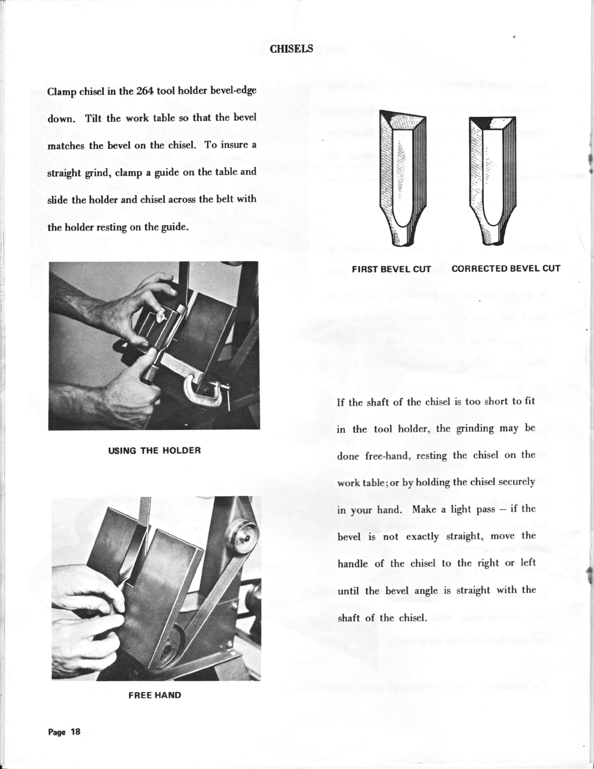
CHITIEI,s
Clamp
chisel
down.
rnatches
straight
the holder
slide
holder
the
Tilt
the
grnd,
resting
264 tool
the
in
work
the
bevel on
clamp
and chisel
on
holder
table so
the chisel.
a guide
the guide.
on the
across the
bevel-edge
that
To
the
insure
table
belt
bevel
and
with
I
a
I
t
I
FIRST BEVEL CUT
CORRECTED
BEVEL
CUT
t,SIlTG THE
HOLDER
If the
in
done
work table;or
in
bevel
handle
until
shaft
the
free-hand,
your
is
the
shaft of
tool
hand.
not exactly
of the
bevel
the chisel.
chisel
the
of
holder,
resting
by holding
Make
chisel
angle
too short
is
grinding
the
the chisel
the chisel
light pass
a
straight,
the
to
is straight
to
may
on
securely
if the
-
move
right or
with
fit
be
the
the
left
the
t
Page
18
FREE
HAI{D

SCREWDRIVER
Clamp
with
Line
face
the
driver
is
edge
screwdriver
the
work table
the
the
up
of the belt
lightly
formed.
in the
at a
90
of the screwdriver
tip
and push
the belt until
into
tool holder
degree
angle.
the screw-
a straight
with
ROTARY
Due to
the length of rotary
LAWNMOWER BLADES
mower blades,
it's necessary to sharpen them with a
freehand
t
already
grind. Grind
on
the blades. Blades with straight
to match the bevel
I
cutting
straight,
edges
even
p:rsses
can be sharpened making
across the belt.
SHARPENING
EDGE BLADE
STRAIGHT
Page
19

If
you
have
a blade
with multi-
cutting
level
sharpening
mend
lower
backstop
Thecurved
without
belt
possible
surfaces
the
(see
before
allows
the
edges,
photo
(see
area
backstoP
photo
that
one
is flexible.
and
belt
both
against
at right).
be
can
below,
has been
to
we recom-
and
uPPer
the
sharPened
fine
a
using
right)
used
This
bend
and
if
match
Don,t
to check
way
cutting
the
curve
the
forget
to
the
edge.
of the
balance
balance.
blade.
the
after
blade
Balancing
sharpening.
should
be
done
our
by
rotary
#277
removing
blade
metal
balancer
from
the
provides
back
of
the
a
quick
blade,
easy
never
PaSe
2()

All of these tools
have a
AXES, HATCHETS AND
standard
bevel of 15 degrees.
CLEAVER
Axes and cleaver
ryEDGES
wedges
should
be
ground
with
a
curved cutting
prevent
burning.
edge.
Hatchets have a
straight edge.
Take several passes
to remove large
nicks in order to
Pw
21

GARDEN
TOOLS
Many tools
should
tools
Tools
This edge
for digging
any sharp edges.
off
Roud
You'll
enablcs you
find sharpcning
SHARPENING
as hoes, shovels,
such
be sharpened
havc
b" fo.-ed
""n
see the edge
to
HOE
THE
spades
free-hand.
cunnell or rolled
a
the belt
using
and gardcn
lawn
being sharpened
digging
and
edgc
which prevcnts
without the
tools a
lot easier
much more
tools can
hackstop,
if thev
casil\
'
. . . THE
be sharpened
nicking
so
that
by rocks
bclt
the
arc cleaned
using
v,'ill
prior to
SHOVEL
belt
the
or
cun'e around
grinder.
hard objects.
other
sharpening.
These
the edge.
This
Page 22
...
THE
LOPPING
SHEAR
...
OTHER
SIDE
OF
LOPPING
SHEAR

HEDGE TRIMII{ERS
are
Trimmers
position
will not
Sharpening
slightly
to drarv
a6 illustrated. This guide
that each tooth is
slop€
as well as the correct bevel.
easi€sl to sharpen
four
by
dislodge motor
depending on manufacturer€rind to existing
screws
can be done quickly
going inlo the base through
parts.)
a guide on the tilting table
will assure
ground to the same
Grind each tooth until the
forms a
edge
across rhe face of the tooth.
smooth
cutting edge
iI you remove
and esily
heveled
lhe blades
tilting tlle
by
from
the electric motor-
base of the tool.
the
table to a 30 d€gre€
angte to insure top
(Use
when removing
care
angle.
performance.)
The blade
(Angle
Use a magic marker
is held in
so you
vary
may
Before
tool, ch€ck
dust,
that may
ening. Danage
removed
Maks sure to use
on
replacing the
rcplacing the blade on the
and remove any grinding
metal shavings, or rolled
have occuned during sharp-
wi result if this is not
before assernbling the blade,
a good coat of oil
each s€ction of the blade belore
blad€ on th€ tool.
edges
?.F
23

HEDGE SHEARS
Before
should
of the shears.
to obtain
down the entire
It's easiest
Belt
down toward the
this
sharpening
separate
an even beveled
to tilt the
Grinder so
way, the
This
length of the
weight of the shear
h"dg" shears
two portions
the
will enable you
blade.
table of
that it
abrasive belt.
is sloping
you
angle
the
In
.
will
provide
for grinding.
side of the
You'll have
a properly
letting
belt,
After
even support
ground
the
sharpening
the proper
Grind
blade on
weight of the
with the flat
cutting
both portions
pressure
the table.
insure
to
edge.
blade
grinding at the
Begin
determine
of the
the pressure
blade in
handle
end
against the belt.
this manner, be
of the
blade - guide
sure to clean
the tool
across
and oil the blade.
the
Page 24

SETTING
FOR INSIDE GRINDING
UP
a
are
Axles
on either the
here show
In drawing
moving
normal
In drawing
Move
the belt
provided
the two
"A"
BG-14 idler pulley to the
position
"B"
BG-14 idler pulley
around
lower pulley.
shown.
Push
front base or rear column.
Place
BG-60
for
using
ways the belt can be
the belt is placed like a triangle,
for most
the
sharpening.
belt is set up
the large upper pulley
belt inside
idler pulley in
until the two sides of the
ment
Z-l2I idler
the idler arm can
to
arm screw. This will
the lower idler pulley
The drawinp
positioned.
position, the
#l
for
inside
to the
position. Loop
#2
and
position
are parallel.
belt
be made
towards
and
#2
by loosening
give you
by
grinding.
large
#3
belt
the
Adjust-
two
as
DRAIYITTG
A
ginding surfaces
tion of the
arrows.
with
the belt running in
For inside grinding remove
Upper
want
the
Pulley,
run the
to sand or grind, and
large
upper pulley.
belt through the opening you
the belt from
replace
then
direc-
the
large
the
the belt
on
DRAW|TTG
8
Ptga
6

SHARPENITTG
KNIVES
USING
THE
#27I
KNIFE
SHARPENING
FIXTURE
Set up
your
outlined.
at rear of
C-clamp
the desired
Use the
fast
For
Turn
operators
belt
Medium-Fine
removal
finish
on
and
Belt Grinder
Fixture
The
worktable
and tilt
angle.
bevel
of metal
work, use
motor.
right,
backstop
for inside
is
then
as
shown.
downward
table
100-grit
(such as
Fine
the
With handle
blade
draw
fixture
of
placed
Secure
to
abrasive
removing
150'grit
of
between
left
from
grinding
in position
with
produce
for
belt
nicks).
belt.
knife to
abrasive
right.
to
as
backstop.
blade
sure
Be
Check
a
tilting
for desired
table
For best results,
strokes.
the
pressure
cause
removal
by
Reverse procedure
Use
desired
or hesitation
discoloration
of
dipping
knife handle
left.
to
lays
bevel
as necessary.
always
as many
metal
water.
is obtained.
is required,
finish
in
for opposite
to left,
Passes
during
of
draw
use
metal.
against
flat
the
readjust
angle
and
light, continuous
necessary
:rs
Using
excessive
the stroke
When
keep blade
blade
of
side
blade
from
until
may
heavy
cool
-
right
Page 26

GENERAL
inspected
BG-6 backstop
The
l.
periodically.
form if the
same
the
definite
a
cause
a
grinding,
a sharp
Wear-grooves
sharpentrg
point
groove
tearing
should
the backstop.
of
in the
bend
in the belt
belt.
the
be
or
always
is
backstop,
ridges can
done on
If there
it wiil
during
SHOPTIPS
GRITTIDER
ABRASIVE
BEVEL
is
GAUGE
FOR
BELT
Backstops
placed.
stop
one
work across
and
Always
2.
a
climate,
to
abrasive
bulb.
extend
a cake
Use the
3.
Use your
great
lighter
work.
is
a
work. Once
arvay;
the same
are inexpensive
If there
should
spot
longer
dry
make a storage
be replaced.
on the belt,
the belt,
belt
sure your
make
area. If you
may find it
you
belts. Install
Its heat will
life. A bread box
their
dish is
deal
Belts can
no reason to
heavier belt
you can use
ideal for this use.
right belt
heavier
of
for
belts
should have been used
a belt is
work
and easily
wear-grooyes, the back-
are
Avoid
instead
inzuring
life.
are stored
belts
live in
a
worth
compartment
a low
keep the belts
for the
grit belts
material
touch-up
be changed
wear out
worn, don't throw
worn
a
as a new belt
wattage
or a
job
you
when
be removed;
to
and
quickly. There
a
light belt because
heavier
a finer grit.
of
using
move the
even
yery
humid
your
for
dry and
lid from
are doing.
there
finishing
on the
belt to
re-
only
\rear
in
while
your
light
a
is
it
do
DRAilI{G
4.
The Abrasive
sindins
i.*cisr"gi.ding
i"g" *t"l
to-the
An B-inch
of the
positiorithe
sindins
i"n line
dotted
the
a ruler
table
ruler. This
exact
For
top
f5 degrees.
as
sho-wn
on the table,
at approximately
Next
B-1.
at
B-2.
made the
belt
machine.
how"a
Abrasive
ruler
grinder
table
belt.
"with
the
lines.
is held
it should
position
degrees.
90
bevel
Utittg
in drawing
the
make
Other
s:rme
A
customers
are
scale
Grinder.
bolted to
be
it is
of
a piece
against
with the
up
is basically
required
in
at right
of
the
grinder
For
angles
be"vel
Belt
can
as shown
so
bottom
The
bottom
If
flush
line
would be
grinding
most saws
a small
table can
12 to l5
a permanent
protector,
With the
B.
be adjusted
frequently used
way.
DRAilITG B
a free-hand
feel more
who
these
easily
can
upright
the
drawing
the ruler
table
of flat stock
the
A-
angles
should
as
shown
bottom
bottom
for grinding
require
tilt the
protractor
to
degrees
as shown
on the
mark
angles can
be
mch
line up
draw-
added
post
First
to the
be
by
the
of
the
of
12 to
table
flat
ruler
be
as
at
at
To determine
against
it lines up
to the
it is
the bottom
column-
neoessar)r
not
with the
desired
the
of the table
mark
Once these
to use
just
angle
on the scale
angles are established
the pro&actor.
lay
and tilt
attached
P4n
a ruler
it until
5.
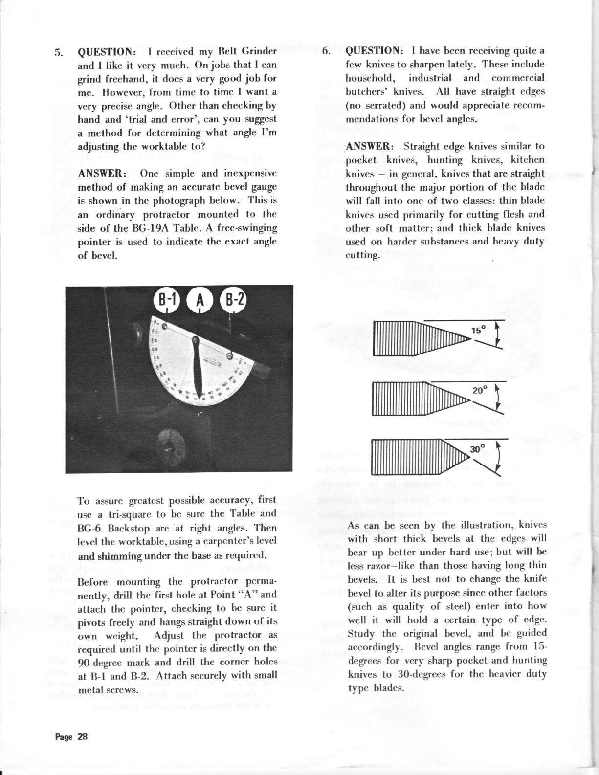
QUESTION:
like it very
I
and
freehand, it
grind
Howevt:r,
me.
very precise
and
hand
a method
adjusting the
angle.
'trial
for determining
worktable to?
ANSWER: One
method
is shown.in
of making
the photograph
an ordinary protractor
is
used
BG-l94,
side of the
pointer
of bevel.
I received
much.
does a
from time
Other
error', can you
and
simple
an accurate
Table. A
to indicate
my llelt
jobs
On
good
very
to time
checking by
than
what
inexpensive
and
bevel
below.
mounted
free-swinging
exact angle
the
Grinder
that
job
want
I
suggest
angle
gauge
'l'his
to the
I
can
for
I'm
6.
QUESTION:
few knives to sharpen lately. These
I have been
household, industrial
a
butchers'
(no
mendations
ANSWER:
pocket
knives
throughout
is
will fall into one
knives
other soft matter;
used
cutting.
knives.
serrated)
and
for bevel angles..
Straight edge
knives, hunting
in general,
-
the major portion
primarily
used
harder substances
on
All
would appreciate recom-
of
and thick
receiving quite a
and commercial
have
straight
knives similar
knives,
knives
two
that
of the
classcs: thin
for cutting
blade
and
include
cdges
kitchen
are straight
blade
blade
and
flesh
knives
heavy
duty
to
assure
To
a tri-square
use
BG-6 Backstop
level the
and shimming
Before
nently,
attach
pivots
own
required
90-degree
at B-l
metal
greatest
worktable
under
mounting
the
drill
the pointer,
freely
and hangs
weight.
the
until
mark
B-2.
and
screws.
possible
to be sure
are at right
a carpenter's
using
,
base
the
the protractor
at
hole
first
checking
straight
pointer
drill the
securely
the
is directly
Adjust
and
Attach
accuracy,
Table
the
angles.
required.
as
perma-
"A"
Point
be sure
to
down
protractor
on the
corner
with small
first
and
Then
level
and
its
of
holes
as
W
M
ffi
edges
will be
long thin
the
factors
into
of edge.
bc guidcd
from
hunting
and
knives
will
knife
how
l5-
duty
As can
be seen
with short
bear up
less
bevels.
bevel to
it
(such as quality
well it
Study
better
razor-like than
It is best
alter its purpose
will hold a certain
the
by the
thick bevels
under
of steel)
original
accordingly. Bevel
degees
knives to 30-degrees
type
for very
blades.
sharp
illustration,
at
hard use; trut
having
those
not to
change
since
enter
bevel, and
pocket
for
the
range
angles
the
other
type
heavier
FaSe 28

a
V€ }now
h.yc
lhc l0BO Bcl6.w
qu€rfiioru .hoot the uee
Abrrrive Bdt gdnd,er
of
equipment do not Ito6;tate to
tfte
uin he e profitrble
ril€ our Cudomer Scrvicc
edditi,on to your froP.
If yor cvcr
DcPldmetrl.
I
belance of tf,is prge
the
-
frR yo'
cET ALONG
'orn'
hes beca
t{otes ud importent rletr lf,rt r
Shop
providcd
WITEOUT" erpeoiry n..hinc.
recrioa wilhin ym Bdt
a r
l rftl in
rarlhg
Grintla lthmrrl rhcrr
yo Gliarlcr rn rheohrtc
ydr c.n
"CAIIT
I
hNr zg
 Loading...