


1

CONTENTS
1. Declaration of conformity ЕС/ЕЕА 3
2. Intended use 4
3. General information 4
4. Main parameters 5
5. List of standard equipment 6
6. Basic components 7
7. Machine structure 12
8. Safety issues 13
9. Marking and packing 16
10. Setting-up procedures 17
11. Basic operations 22
12. Maintenance and repair 30
13. Troubleshooting 32
14. Storage 33
15. Transportation 33
16. Disposal 33
Warranty certificate 34
Acceptance certificate 36
2

This operating manual establishes machine service instructions and rules of safe operation.
Please read all instructions contained in this operating manual before using the machine.
The woodworking machines, if not operated safely, may endanger human life and health.
Hazardous exposure: noise, vibration, dust and cutting wastes, electricity.
Compliance with the requirements, specified in the operating manual, ensures safety while in
use and helps to avoid problems during operation and maintenance.
This operating manual does not reflects slight changes and modifications in machines, made
by the manufacturer after the publication of this manual, as well as changes in component
details and documentation attached to it.
1. DECLARATION OF CONFORMITY ЕС/ЕЕА
Joint limited liability company “Zavod Belmash” declares that multifunctional woodworking
machines
BELMASH SDM-2000
BELMASH SDM-2200
BELMASH SDM-2500
comply with the following requirements of EU Directives, including changes:
2006/42/EC Machinery (MD)
2004/108/EC Electromagnetic Compatibility (EMC)
2011/65/EURO HS Directive
A basis for concordance of the mentioned above devices with the EU Directives is their full
compliance with the applicable standards listed below:
EN 61029-1: 2009 + A11: 2011
EN 62233: 2008 (incl. Corr: 2008)
EN 55014-1: 2006 + A1: 2009
EN 55014-2: 1997 + A1: 2001+A2: 2008
EN 61000-3-2: 2006 + A1:2009+A2: 2009
EN 61000-3-3: 2008*
EN 61000-3-11: 2010**
01/222-1*
01/222-2**
_____________________________________________
* - for machines BELMASH SDM-2000
** - for machines BELMAS SDM-2200, BELMASH SDM-2500
Director _____________ D. V. Shorikov
Conformity certificates are stored at the address:
Zavod Belmash JLLC, Slavgorodskiy Proezd, 37 Republic of Belarus, 212000, Mogilev.
3

2. INTENDED USE
The machine relates to equipment for the domestic individual use.
The hand-fed machines are used for processing of wood and analogous hard materials
(cardboard, plywood, wood chip boards) by planing, cutting, milling and drilling in order to
give them the required shapes and sizes.
Do not use the machine for other purposes. It is not allowed to process metals, stone,
asbestos-cement materials, soft plastic and rubberlike materials
With appropriate adjustment the machine can perform the following types of processing:
planing (jointing) on surface or along ribs;
angular planing (jointing, along ribs);
longitudinal and cross cutting;
longitudinal angular cutting with the use of a ruler;
angular cross cutting with the use of device;
milling with disc cutters;
milling with end cutters;
drilling.
3. GENERAL INFORMATION
The machine can be operated outdoors, under cover, indoors, except for residential premises.
Climatic service conditions:
altitude above the sea level – up to 1000 m;
environment temperature from +5 to +40°С;
environmental relative humidity – up to 80%, at a temperature of +20°С.
It is not allowed to operate the machine under the impact of drops and splashes, as well as
outdoors during rain, fog, snowfall, strong wing, and storm.
The power of the machine is supplied by a single-phase AC with an earthed positive earth.
BELMASH SDM-2200 и BELMASH SDM-2500 machines shall be used in the electrical grids
with a nominal impedance z
sufficient for the mentioned above machines with Electric Inspection Service.
Type of engine – asynchronous, single-phase, with the working capacitor, intermittent
operating status – S6-40%.
The equivalent and maximum sound levels are as follows: 80 dBA and 90 dBA relatively.
The machine has a built-in disconnect device from the power supply during
engine overheating. Restarting of the machine can be performed after the electric motor has
cooled down to the ambient temperature.
=0,354 ohm. The user must agree on the rated load capacity
max
asynchronous
To connect the external exhaust units in order to collect dust and cutting wastes, the
woodworking machine has three pipes:
a pipe with 63 mm in diameter on casing for chip removing 24 (Fig. А);
a pipe with 38 mm in diameter on casing of saw blade 30 (Fig. А);
a pipe with 28 mm in diameter on fencing of saw blade 29 (Fig. А).
The external exhaust unit should be suitable for removing cutting wastes.
4

4. MAIN PARAMETERS
Main parameters are specified in the Table 1.
Parameters
№ Name
1 Max. planing width per pass, mm 230 250 270
2 Range of planing depth per pass, mm 0÷3 0÷3 0÷3
Max. height of the work piece pressed by a holding
3
down device, up to, mm
Max. uncut dimensions, length×width×height
4
(depth), mm
5 Range of cutting depth, mm 0÷85 0÷100 0÷117
6 Range of cutting depth per pass, mm 250 280 315
7 Diameter of disc cutter 125 125 125
Diameter of mounting bore of disc cutter/ saw
8
blade, mm
8 Diameter of end cutter, mm 612 612 612
BELMASH
SDM-2000
65 65 65
2000×230×85 2000×250×100 2000×270×117
32 32 32
BELMASH
SDM-2200
Table 1
BELMASH
SDM-2500
Range of longitudinal cutting angles and planing
9
with the use of a ruler, degrees
Range of cross cutting angles with the use of a
10
device, degrees
11 Cutting table dimensions, mm 732×456 802×492 872×532
12 Dimensions of tables during planing, mm 760×247 830×267 900×287
13 Milling table dimensions, mm 470×190 470×190 470×190
Rated idle RPM of a knife’s block and end cutter,
14
15 Rated idle RPM of a saw blade and disc cutter, min-1 2850 2850 2850
16 Rated consumed power, W 2000 2200 2500
17 Rated frequency, Hz 230 230 230
18 Rated frequency, Hz 50 50 50
19 Overall dimensions, L×B×H, mm 806×793×445 876×829×460 949×849×512
20
-1
min
Setting dimension, L
for the installation of the machine), mm
(min. the size of the site
1×B1
0÷45 0÷45 0÷45
–45÷45 –45÷45 –45÷45
7700 7700 7700
430×206 430×226 441×246
21 Weight of machine including devices (net/gross), kg 52,4/55,3 56,1/59,2 61,3/64,9
Limit deviations of linear and angular dimensions do not exceed ±5%
Limit deviation of the rotating frequency does not exceed ±5%
Limit deviation of the power consumption +15%
5

5. LIST OF STANDARD EQUIPMENT
Quantity, pсs
№ Item Name
Devices, tools, fencing
1 -
2 28, 29
3 11, 12 Angular bump as a set with a ruler 1 1 1
4 34 Device for angular cross cutting 1 1 1
5 41-44 Vertical holder 1 1 1
6 56 Chuck screw wrench 1 1 1
7 68 Hook wrench 1 1 1
8 7 Knife’s block fencing 1 1 1
9 8 Bracket 1 1 1
10 46 Milling table 1 1 1
11 51 End mill fencing 1 1 1
12 45 Insert for milling 1 1 1
13 24 Casing 1 1 1
14 22
74
75
76
77
78
79
23
80
81
23а
15 - Pusher 1 1 1
Standard articles
16** 25 Circular saw blade 1 1 1
17 55 Drilling chuck 13-М12×1,25 1 1 1
18** - Fixing arrangements 1 set 1 set 1 set
19 - Hex key 1 1 1
Documentation
20 - Operating manual 1 1 1
21 - Warranty certificate 1 1 1
Personal protective equipment
22 - Earplugs 1 set 1 set 1 set
23 - Protective goggles 1 1 1
24 - Mask 1 1 1
** – Fixing arrangements can be installed on the machine or its tools and devices
Portable multifunctional woodworking
machine
Fencing of saw blade and disc cutter
together with the splitting knife
Holding down device
Spring box
Right support
Left support
Rotation axis
Clamp axis
Clamp handle
Screw М5×12
Screw nut М8
Spring washer 5
Spring washer 8
BELMAS
SDM-2000
1 1 1
1 1 1
1
1
1
1
1
1
1
4
2
4
2
BELMASH
SDM-2200
1
1
1
1
1
1
1
4
2
4
2
Table 2
BELMASH
SDM-2500
1
1
1
1
1
1
1
4
2
4
2
6
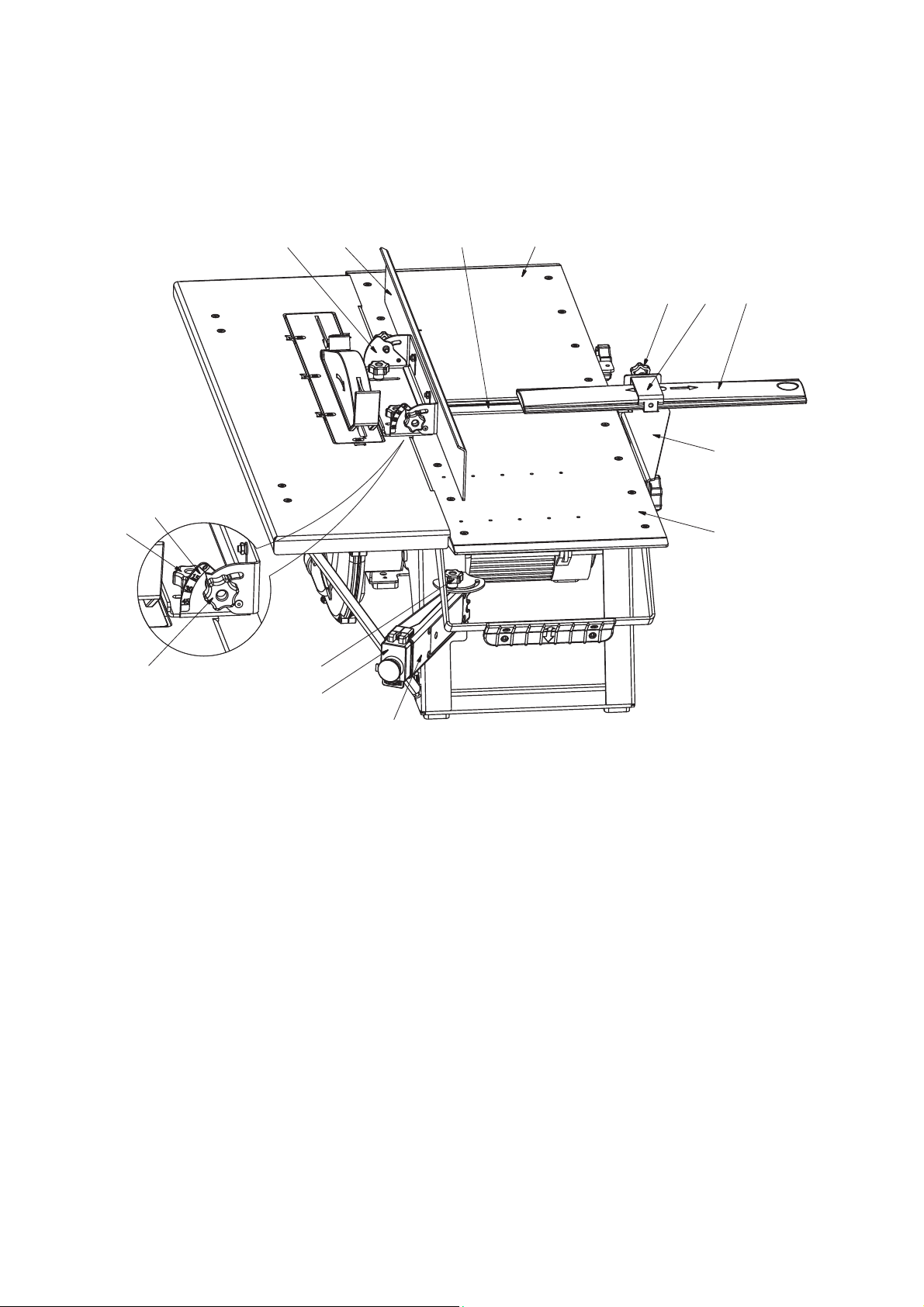
6. BASIC COMPONENTS
16
17
13
11
21
20
12
1
3
10 9 7
8
2
18
Fig. A
Planing function
1 – Knife block
2 – Loading table
3 – Outfeed table
7 – Knife’s block fencing
8 – Swing bracket for knife’s block fencing
9 – Clip for fixing of knife’s block fencing
10 – Flywheel for clip fixing
11 – Angular bump (vertical)
12 – Gib stick of angular bump (vertical)
13 – Cutting/planing angle scale (vertical)
16 – Flywheels for angular bump fixation (vertical)
17 – Flywheels for cutting/planning angle fixation (vertical)
18 – Swivel control panel
20 – Safety switch cover
21 – Flywheel for control panel fixation
7

В1
24
27
31
59
60 30
28
25
37
36353429 12
26
33
38
32
39
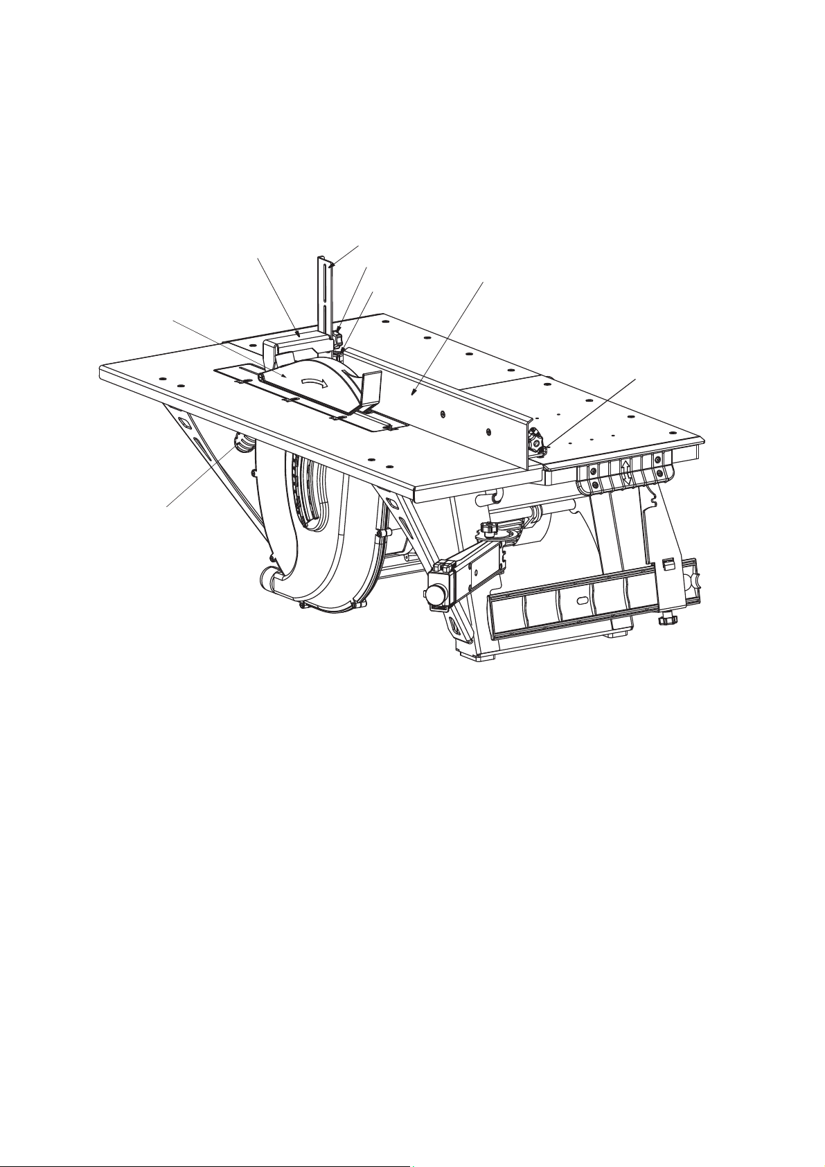
B2
25 67
32
Fig. В1, B2
Cutting function
12 – Gib stick of angular bump (vertical)
24 – Pipe for cutting wastes
25 – Saw blade
26 – Cutting table
27 – Stick for lifting and lowering of saw blade
28 – Splitting knife
29 – Fencing of saw blade / disc cutter above the table
level
30 – Fencing of saw blade / disc cutter below the table
level
31 – Cutting table mounting
32 – Flywheel for fixation of saw blade / disc cutter
33 – Hold slide for angular cross cutting
34 – Device for angular cross cutting
67 40 45 32
35 – Angular cross cutting scale
36 – Flywheel for bum fixation
37 – Cutting depth scale
38 – Depth scale of milling with disc cutter
39 – Tool-slide indicating cutting/milling depth
40 – Disc cutter (not included in the scope
of delivery)
45 – Insert for cutter guard below the tale level
56 – Box wrench
59 – Screw nut for splitting knife fixation
60 – Washer lock for splitting knife
67 – Screw nut for saw blade/ disc cutter fixation
68 – Hook wrench
68
56
8
27
29
42
41
44
43
12
11
Fig. С
Milling with disc cutter
11 – Angular bump (vertical)
12 – Gib stick of angular bump (vertical)
27 – Stick for lifting and lowering of saw blade
29 – Fencing of saw blade / disc cutter above the table level
41 – Vertical rod for fencing of disc cutter
42 – Horizontal rod for fencing of cutter
43 – Flywheel for vertical rod fixing
44 – Flywheel for horizontal rod fixing
9

64
55
52
53
51
12
47
58
54
48 50 46 49
Fig. D
End milling function
11 – Angular bump (vertical)
12 – Gib stick of angular bump (vertical)
16 – Fixing handwheels of angular support (vertical)
46 – Milling table
47 – End milling cutter (not included in the scope of delivery)
48 – Brackets for cutter accessory
49 – Lever-stick for lifting/lowering/of milling table
50 – Flywheels for fixation of cutter accessory
51 – Fencing of end milling cutter
52 – Lock bracket for operating mode disabler
53 – Rod for operating mode disabler
54 – Fixing screws for brackets of cutter accessory
55 – Drill chuck
58 – Wrench for drill chuck
64 – Fixing screws for end mill fencing 51/knife’s end block fencing 65
16
11
10
14
63
22
4
62
6
19
61
23
64
66
65
24
6
5
15
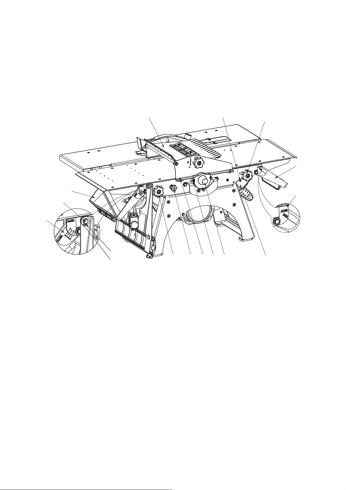
Fig. Е
Planing with holding down device
4 – Lever-stick for lifting and lowering the loading table and transferring the machine
5 – Lever-stick for lifting and lowering the outfeed table and transfer machine
6 – Flywheels for fixing loading and outfeed tables
14 – Planing depth scale
15 – Loading table scale
19 – Handwheel for fixing bracket 8
22 – Holding down device
23 – Fixing screws for holding down device
24 – Pipe for cutting wastes
61 – Washer locks for swing bracket of knife’s block fencing
62 – Lock ring for swing bracket of knife’s block fencing
63 – Axis for bracket 8
64 – Fixing screws for end mill fencing 51/knife’s end block fencing 65
65 – Knife’s end block fencing
66 – Fixing screws for cutting wastes pipe 24
11

7. MACHINE STRUCTURE
The machine is an electromechanical device. The woodworking machines are powered with
the help of asynchronous electromotor. Rotation from the motor to the knife block (outlet
end of the knife block) and saw blade is performed with the help of multiple vee belt drive.
The belt covers driving pulley and two driven pulleys. The first of the driven pulleys generates
the rotation of the saw blade, and the other one generates the rotation of the knife block and
the end mill cutter. The belt tension is performed automatically as a result of the
electromotor and traction coil weight.
The woodworking machines are equipped with the interlocking devices, which allow
performing only one type of processing: cutting/milling with disc cutter or planning/milling
with end mill cutter.
The machine has a stationary table for cutting and two replaceable tables for planning
(outfeed and loading tables). Planing tables, when used in cutting mode, complement cutting
table.
In the planning mode, the loading and outfeed tables are mounted at the level of slicing
blade cut. Besides, the front table can move down below the level of the slicing blade cut.
That provides the necessary planning depth.
In the cutting mode, the planning tables are mounted at the level of cutting tables, forming a
single-piece area of cutting table. In this case, planning tables cover the rotating cutter block,
ensuring safe operating. Displacing of tables is performed with the help of the in-built leversticks. Such a construction helps to easily and quickly readjust the machine to the necessary
type of processing.
Machine stop has special protection from spontaneous shutdown. It is installed on the
mobile bracket, rotating to ensure accessible switch-on/switch-off of the machine.
The tables serve as a basic supporting surface for a workpiece.
The machine has an angular bump with a ruler and a device for angular cross cutting to
ensure the right location of the workpiece to a cutting tool and the forward, straight,
longitudinal motion.
In order to avoid saw blade jamming during cutting, there is a splitting knife in the machine
construction.
The woodworking machine is equipped with protection devices to prevent access to rotating
parts of the device.
The design includes portable hinged guard to prevent access to the cutter block.
To prevent access to a saw blade /disk cutter, stationary fencing is located below the cutting
table and movable fencing – above.
The design includes end mill fencing to prevent access to end mill/drill.
To prevent access to the end of the rotating cutter block (while the milling device is not
operated) – stationary protection device – end mill fencing.
The machine is equipped with measuring scales, indicating the cutting depth, milling with
disc cutters and planning depth.
12

8. SAFETY ISSUES
Before starting to use the machine the user shall take into account his physical state,
qualification and complexity of tasks. Persons operating the woodworking machines must be
at least 18 years of age and must study the operating manual.
IT IS FORBIDDEN:
to work under the influence of alcohol or other intoxicating substances;
to expose the machine to dripping and splashing, as well as using it outdoors during rain
and snowfall;
to leave the machine unattended while it is connected to the supply mains;
to provide access to the machine to people, who do not have any professional knowledge
in this sphere;
to use the machine for purposes other than that intended;
to process metals, stones, asbestos-cement materials, soft plastic and rubberlike materials.
IT IS FORBIDDEN to use the machine if any of the following problems occur during its
performance:
damage of plug-and-socket connection, power cord;
damage of ground circuit;
if you smell fume or odor, typically occurring during burning insulation;
failing operation of the switcher;
formation of loud noise, hammering, vibration;
damage or cracks in the basic parts, fencings, casings.
The machine must be disconnected using the switch in case of spontaneous stop (during
rotating parts jamming, etc.). Always place the appropriate cover over the switch during work
breaks.
When connecting the machine it is recommended to use automatic safety fuse or fuse with a
rated current equal to 16А.
Use the plug to disconnect the machine from the supply system:
while changing the working tool (disc cutter, knifes, etc.), installing accessories or
adjusting;
while transferring the machine from one working place to another;
during work breaks, when the work is completed;
during technical maintenance;
while removing cutting wastes.
Power cord of the machine must be protected from accidental damage (it is recommended
to hang it). Direct contact of the electrical cord with hot and oily surfaces is forbidden.
While working outdoors it is permitted to use the original, app
cord.
Always make sure that the workpiece does not contain nails or foreign objects.
When processing short and narrow pieces use a secure workpiece infeed (paragr. 8.6).
ropriately marked extension
Do not wear too loose clothing and jewelry. They can get to the moving parts of the machine.
When working outdoors it is recommended to use gloves and slip-resistant footwear. Wear
appropriate personal protective equipment and head covering.
13

To ensure high-quality and safe operation, the cutting part of the working tool must be sharp
and clean. Follow the instructions to replace the accessories.
8.1 Workplace requirements
The workplace should be determined taking into account the location of the workpieces ,
direction of their movement, and junkyard location;
Space around the entire perimeter of the working tables should be empty. Working
clearance is necessary for direction, infeeding and unloading of workpieces taking into
account their overall dimensions and weight;
The floor must not be slippery or have any obstacles;
Keep the machine and workplace clean;
The workplace should be well lit by natural sunlight or artificial light. Using fluorescent
lighting causes stroboscopic effect that may lead to incorrect identification of rotating
direction of moving machine parts;
Ensure proper ventilation when working indoors, for example, with the help of air vent or
by proving air supply;
Do not work in the rooms with explosive or chemical environments;
Comply with safety regulations when working indoors. A fire extinguisher is a must.
8.2 Additional safety measures
Keep children and unnecessary persons away from a working area;
Ensure you always have a firm and safe footing. Do not attempt to reach the object that
are out of distance;
When working avoid contact with grounded devices (for example: pipelines, electric
cookers, refrigerators );
Do not stand in the area of the plane of saw blades. Keep to the left or to the right side
from them;
Please attend, mind what you do, do not use the machine when tired;
Do not use damaged or distorted saw blades and knives;
Use the saw blades, knives, cutters and equipment, recommended by the manufacturer;
Notice that the choice of the saw blade depends on the work material;
Use the splitting knife and adjust it in the appropriate manner;
Use head guard (casing) of the saw blade and adjust its location appropriately;
Do not overload the machine;
Do not process too small and too short workpieces;
Replace the plastic insert of the saw blade when it is worn out.
8.3 Operational hazards
The following types of hazards may appear even if the machine operates properly:
Risk of injury from a flown away workpiece;
Risk of injury from breaking parts of the workpiece;
Risk of noise and dust;
Danger of electric shock due to improper laying of the power cord.
To reduce the noise impact, when operating at the machine, always wear personal protection
equipment to prevent hearing damage (earplugs). It is recommended to use a dust mask to
protect the respiratory tract from dust particles.
14

The figures of equivalent and ceiling sound level (p. 3) are the levels of radiations but are not
necessarily the safe operating levels. Despite there is a correlation between levels of radiation
and noise impact, they can be reliably used to determine if further protection measures will
be required.
Factors that influence on the actual level of noise impact on the user include not only the
characteristics of working space (open air, under cover, enclosed space and its sizes), but also
other noise sources, namely, the noise from the other related processes. This information
allows the user of the machine to make a risk assessment and take care of the necessary
safety precautions.
Precautionary measures herein refer to the reducing of the noise dose by cutting time spent
in the work area, using of individual protective equipment such as earplugs, hearing
protectors, etc.
Allow only qualified persons to inspect and service the machine and use only original spare
parts.
8.4 Workpiece requirements
The workpiece weight must not exceed 50 kg.
The maximum workpiece dimensions are listed in Table 1. When processing workpieces of
greater length, it is necessary to use special trays that should be installed under the hanging
end of the workpiece, or work in a pair with someone. The minimum height of the workpiece
during planing or sawing should be not less than 5 mm.
Workpiece should be checked for the presence of metallic or mineral inclusions (nails,
staples, splinters, stones etc.) Do not process materials containing cracks, black knots, rot of
wood or other wood defects.
IT IS FORBIDDEN: to cut flat the workpiece (“round wood”) without a special carriage (not
included in the scope of delivery).
When crosscutting the “round wood”, supply is performed by moving the workpiece along
the table, rather than by rolling.
The workpiece shall not be wet. The recommended humidity should be up to 12%.
8.5 Working stance and workpiece supply
The proper working stance of the user is standing position. To supply workpieces to the
machine, the user should stand aside, next to the workpiece.
When jointing, move the workpiece along the loading table, pressing it by ruler. It is
necessary to keep the fingers together and hold the workpiece with both palms at the top.
Proper hand position is when one hand is on the upper workpiece sawn face, above the
loading table.
It is necessary to plane the workpieces along the full length without moving it back over the
rotating knife block. The workpieces with a thickness less than 50 mm should be planed with
the help of the holding-down device (p. 10.1.6).
When sawing and millingб the workpiece should be kept with fingers and moved smoothly
along the loading table, without cramping it, with the help of the ruler and cross cutting
device.
15

Keep your hands at a safe distance from the cutting place.
The workpiece supply should be steady (without jerks). The table speed should provide the
smooth running of the machine to avoid overloading.
To process short workpieces (with length less than 300 mm), use special devices for secure
workpiece supply (pushers).
8.6 Devices for secure supply of the workpiece
To ensure secure supply, use wooden pushers that are designed to fit the specific workpiece.
The pushers are made by the user himseft. The minimal length of the pushing part should be
at least 400 mm.
The examples of the pushers are shown in the Fig. F.
50
400
90˚
25˚±5˚
S=25
Fig. F
Pushing rails
9. MARKING AND PACKING
There is a plate with information about the parameters of the power supply on the machine
stand. It is recommended to comply with these requirements when connecting the machine
to the network.
It is necessary to observe the symbols on the packaging during transportation and storage.
85÷117 mm
Ø
250÷315 mm
230÷270 mm
Ø
55 мм
Ø
125 mm
16

Consider the tool sizes and do not use adapters for them. Use the tool recommended by the
manufacturer. When working, consider the maximum allowable finished dimensions.
Information on the types of processing is listed on the label on the fencing of the 30 (Fig. B1)
saw blade below the table level.
There is a threat-warning label on the swivel control panel 18.
Do not put your hands in the working area the machine is switched on. It
may result in risk of injury due to rotating parts.
Use a dust mask.
Always wear personal protection equipment to prevent hearing damage. The
noise exposure can cause permanent hearing loss.
Wear eye-protection goggles.
Never dispose this tool together with unsorted municipal waste. In
accordance with the European Directive 2002/96/EC on waste electrical and
electronic equipment and its implementation into national law,
nonfunctioning power tools must be collected separately and recycled in an
environmentally suitable manner.
There is an icon on the lever 27 showing moving direction when lifting or
lowering the saw blade.
The machine is packed in an individual carton box with two handles.
10. SETTING-UP PROCEDURES
During setting-up procedures it is necessary to perform:
assembly;
installation;
knife setting;
startup.
10.1 Assembly
First of all, you must set up the machine on the table and assemble the auxiliary machinery
and fencing included in the scope of delivery.
Adjust the saw blade insert (p. 10.1.1);
17
Install fencing of saw blade together with the splitting knife (p. 10.1.2);
Install the device for angular cross cutting (p. 10.1.3);
Install the knife’s block fencing together with the bracket (p. 10.1.4);
Install the milling table (p. 10.1.5), in case you are going to perform planning with end mill
cutter or drilling;
Assemble the holding down device (p. 10.1.6).
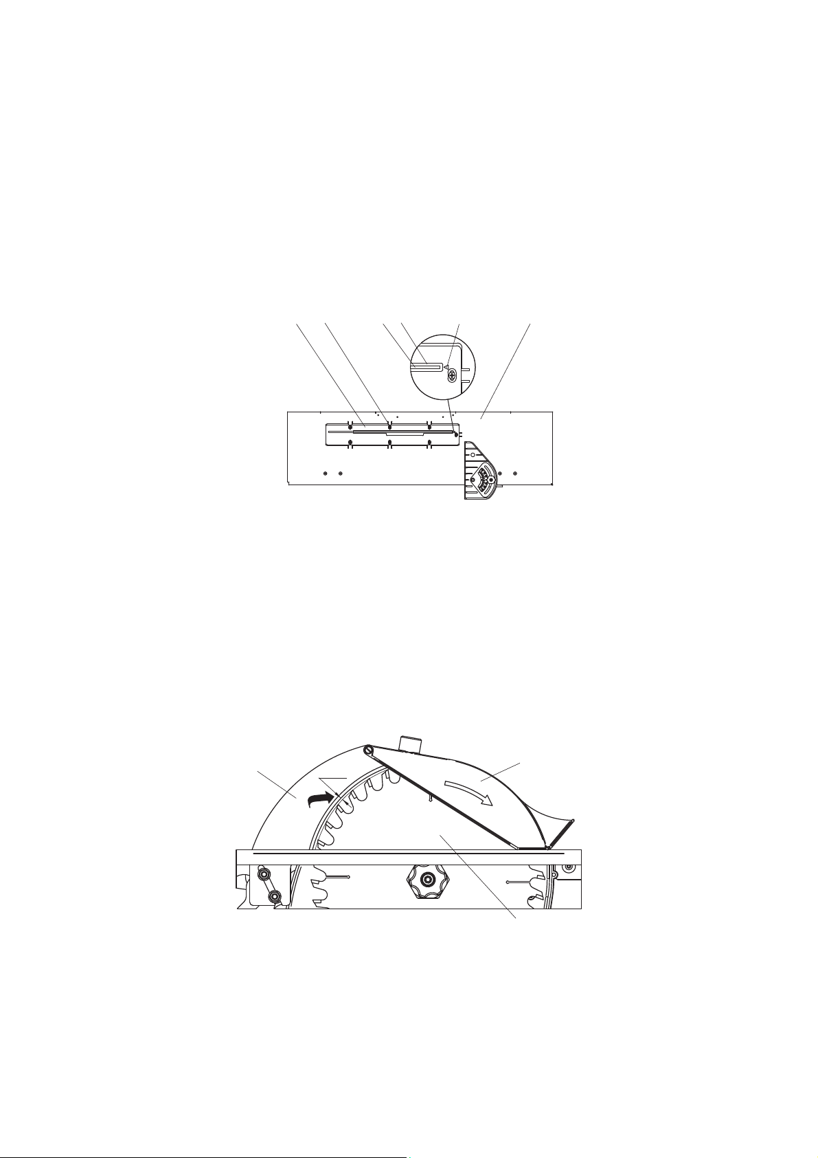
10.1.1 Adjusting the saw blade
The saw blade insert 31 must be adjusted so that the mark “▼” 31b (Fig. G) shall coincide
with the center of the saw blade 25, and the slot 31 shall be parallel to the plane of the saw
blade 25. It requires releasing the screws 31c, adjusting the insert 31 and setting it back.
25
31c31
31a
31b
26
Fig. G
Adjusting the saw blade insert
25 – saw blade, 26 – cutting table; 31 – cutting table insert; 31а – slot; 31b – mark; 31c – screws
10.1.2 Installing the fencing of saw blade with the splitting knife
In order to install the fencing of saw blade with the splitting knife it is necessary to pull its
end with the sweep slot to the slotted hole of the insert and push on two threaded rods until
the sweep slot is positioned between the washers 60 and screw nuts 59 (Fig. B), pre-installed
on the threaded rods.
Next, you need to adjust the position of the splitting knife.
28
5 mm min
Fig. H
Radial distance
25 – saw blade, 28 – splitting knife; 29 – fencing of saw blade
18
25
29

This requires inserting the saw blade to the maximum cutting depth. The splitting knife shall
be placed symmetrically in the center in the plane of the saw blade, providing radial distance
between the splitting knife 28 and the crown of the saw blade equal to 5 mm (Fig. H). It is
achieved by moving the washers with screw nuts 59, 60 (Fig. B1) and the splitting knife 28
with a sweep slot along the threaded rods 59.
Fencing of saw blade shall be mounted on the machine during all types of processing.
10.1.3 Installing the device for angular cross cutting
Installation of the device for angular cross cutting 34 (Fig. В) is carried out by putting it into
the cam with a flange of the cutting table 26, which serves as a guideway for supplying the
workpiece along the cut line. To remove the device from the machine, perform the
mentioned above actions in the inverse order.
10.1.4 Installing the knife’s block fencing together with the bracket
9310
62
781963 61
Fig. I
Installing the knife’s block fencing together with the bracket
3 – outfeed table; 7 – fencing; 8 – bracket; 9 – clip; 10 – flywheel for clip fixation; 19 – flywheel for bracket fixation,
63 – axis; 61 – washer, 62 – lock ring
To install the knife’s block fencing, insert the fencing 7 (Fig. I) between the bracket 8 and the
clip 9 and then fix it with the help of the flywheel 10.
The bracket with the fencing should be installed on the axis 63 and fixed with the help of the
washer 61 and the lock ring 62.
The fencing should be installed on the plane of the outfeed table 3 and fixed with the
flywheel 19.
10.1.5 Installing the milling table
The install the milling table 46, fix it to the machine stand with cap screws 19 (Fig. D).
10.1.6 Assembling the holding down device
The holding down device 22 (Fig. E) is designed for safe processing of the workpieces with
19
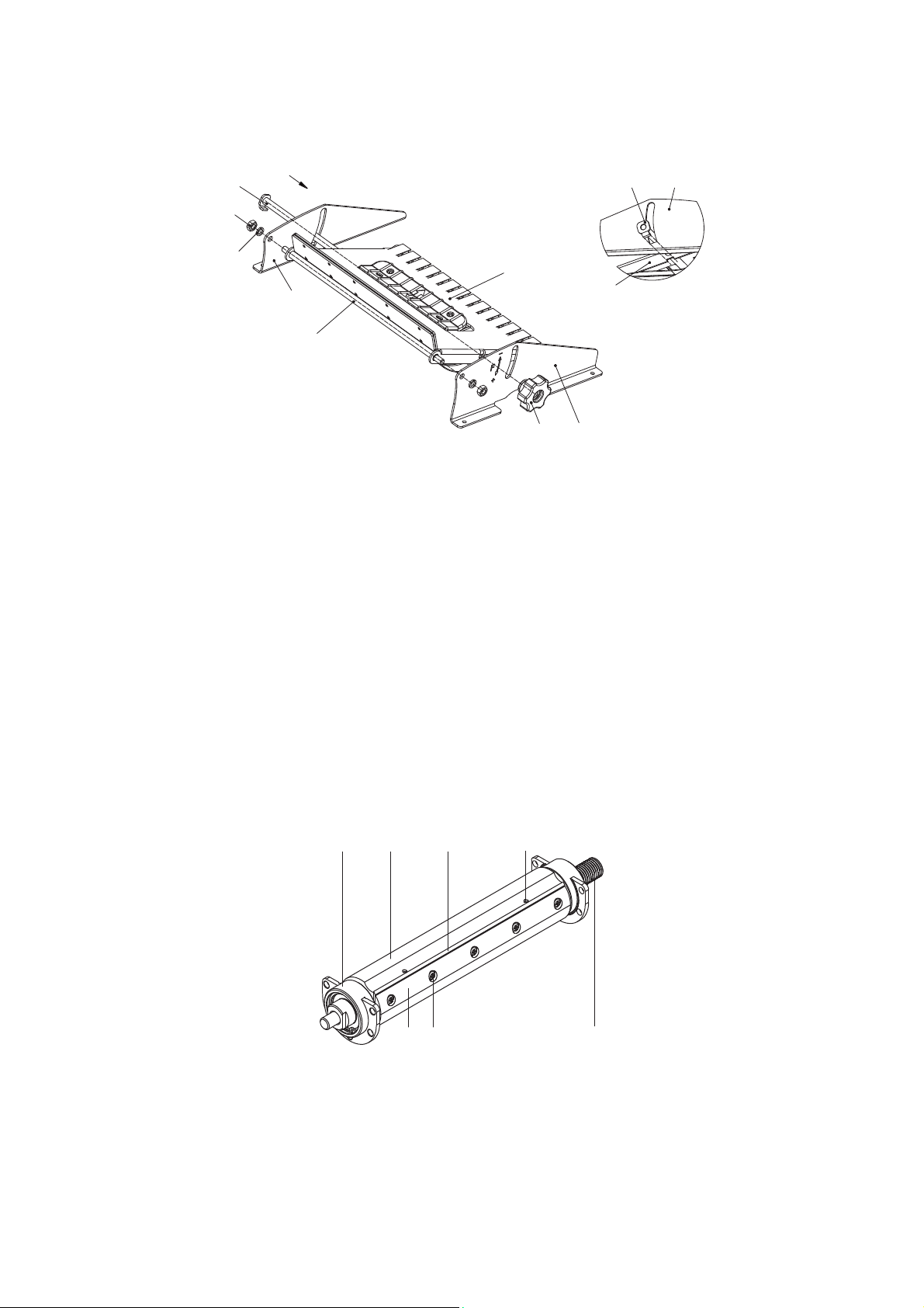
the thickness less than 60 mm. It is shipped dismounted. The kit of parts (Table 2) is packed
A
A
in a separate box. The assembly of the holding down device is performed as shown in the
Figure J. To fix the holding device, use screws 23 and 8-mm washers.
78
80
81
76
77
74
79
78
74
75
76
Fig. J
Holding down device
74 – spring box, 75 – right support, 76 – left support, 77 – rotating axis, 78 – clamp axis, 79 – clamp handle,
80 – screw nut М8, 81 – washer spring
10.2 Setting up the machine
Install the machine on a freely accessible, sturdy, level surface. It is useful to additionally
scerw the machine with the help of mounting bolts (not included in the scope of delivery).
The holes in the bearing surface of the machine feet serve for mounting.
Check the intactness of the basic parts; fastening security of the separate parts; bolts, screws
and nuts tightening; locking; integrity of the supply cord, plug and socket; availability of the
safety fencing.
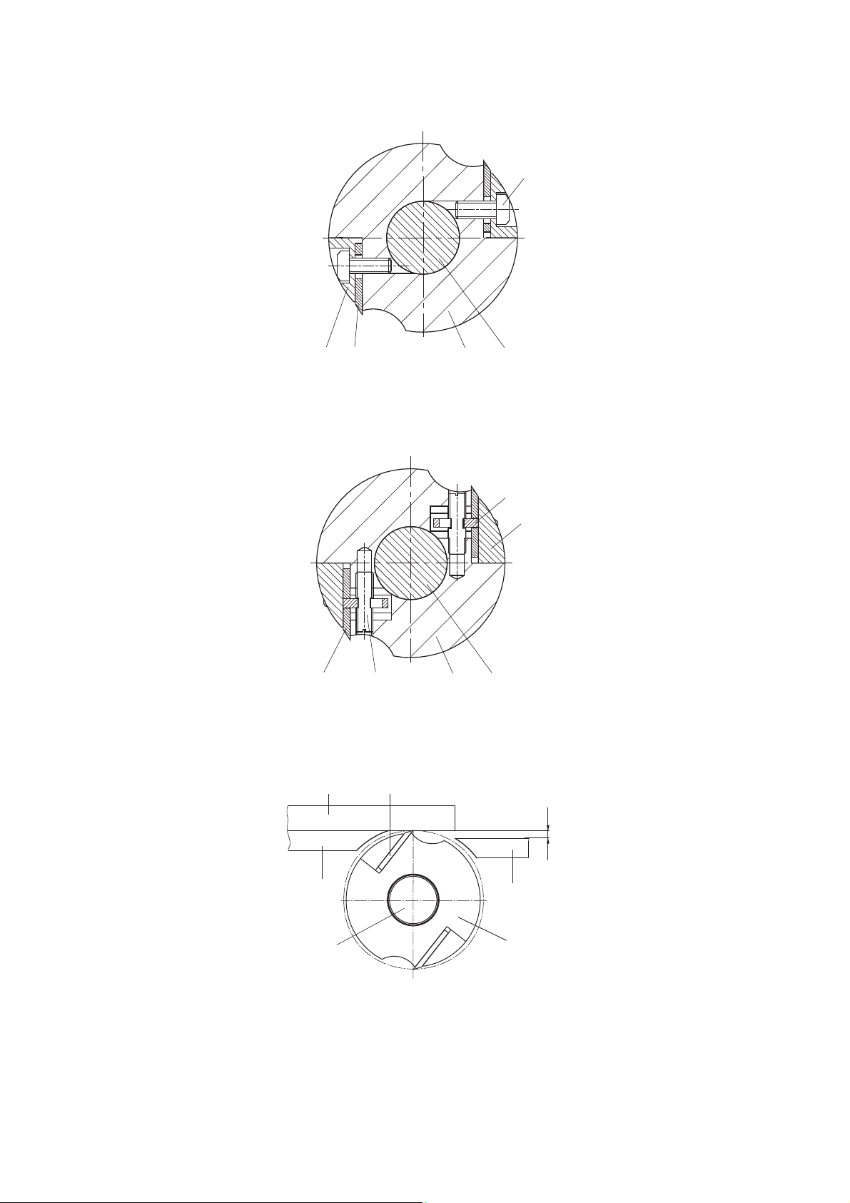
10.3 Installing and adjusting the knives
The knife adjustment is performed by consistent installation of each blade. It is necessary to
loosen the knife 70 by removing five screws 71 in advance. (Fig. K).
1a1b
70 72
69 71
1
Fig. K
The cutter block construction
1 – cutter block; 1а – block casing; 1b – end shields; 69 – knife holder; 70 – slicing blade;71 – fixing screw for the
knife holder; 72 – adjusting device
20
Adjust the knives by tightening / unscrewing the screws 71 so that the knife edge touch the
ruler 12, mounted on the receiving table 3 (Fig. N)
71
1a69 70 1
Fig. L
Knife mounting
1 – cutter block; 1а – block casing; 69 – knife holder; 70 – slicing blade; 71 – fixing screw for the knife holder
73
69
1a7270 1
Fig. M
Adjusting device
1 – cutter block; 1а – block casing; 69 – knife holder; 70 – knife; 72 – adjusting screw; 73 – flag
12 70
H
3
1
2
1a
Fig. N
Scheme of knife adjustment
1 –cutter block; 2 – loading table; 3 – infeed table; 12 – ruler; 70 – knife; Н – required milling depth
Fix the knife by tightening the binding screws 71. After that check the proper knife
21

installation. If required, repeat the installation again.
The cutting edge of properly installed knives should touch (up to 0,1 mm) the lower edge of
the ruler 12 during cutting block rotation.
10.4 Machine startup
Machine startup is performed with the help of the switcher after adjusting the processing
type. The switcher is located on the swivel control panel 18 (Fig. A) that has two positions:
1 position – to operate in the jointing and cutting mode. The swivel control panel with the
switcher is installed on the accessible area from the left side of the outfeed table 3;
2 position – to operate in the milling mode. The swivel control panel with the switcher is
turned and installed all the way to the right in the accessible work area.
To change the switcher position, release the flywheel 21, turn the swivel control panel with
the switcher and fix it again with the flywheel.
To start up the machine it is necessary:
to connect the machine’s plug to the mains;
to unlock and open the switch cover, push the green button.
To switch off the machine it is necessary to:
push the red button;
or close the switch cover.
The start-up time of the machine is less than 5 seconds. In case the machine fails to start, turn
it off with the switcher. If the problem remains, restarting is performed in no event sooner
than 1 min.
After the end of work, the switch cover must be shut off.
11. BASIC OPERATIONS
11.1 Рlaning (jointing) on surface, along ribs and at an angle (along ribs)
Before starting, it is recommended to make the following adjustments:
to install the planing table;
to adjust the planing depth;
to adjust and install the fencing;
to install the ruler;
to install the holding device (for workpieces with thickness less than 50 mm).
To switch to the planing mode it is necessary to lower the saw blade below the table level
until the indicator needle will be in line with the mark "min" on the cutting depth scale
(p.11.2.2).
22

11.1.1 Installing the planning table
The loading 2 and outfeed 3 tables should be installed at the level of the slicing blade cut (Fig. O).
To get that done:
loose the flywheels 6;
pull the locking clip 52 (horizontally) by holding it from the bottom, and lower the tables
by moving the lever-sticks 4 and 5 down against stop;
the bracket 8 with fencing 7 should be mounted on the plane of the outfeed planing table
3 and fixed with the help of the flywheel 19.
9362
5
4
7819 5214a14 6
Fig. O
Installing planning tables
2 – loading table; 3 – outfeed table; 4 – lever-stick of the loading table; 5 – lever-stick of the outfeed table;
6 – flywheels for loading and outfeed table fixation;7 – knife’s block fencing; 8 – swinging bracket; 9 – fixation clip;
14 – scale, 14а – survey-line of the planning depth; 19 – flywheel for bracket fixation; 52 – locking clip.
11.1.2 Adjusting the planing depth
To adjust the planning depth, perform the following (Fig. O):
unscrew the flywheel 6 of the loading table 2;
move the table to the desired planing depth (0÷3 mm) by moving up/down the lever-stick
4, aligning the survey-line 14a on the loading table with the appropriate value on the scale
14;
fix the loading table 2 in this position by tightening the flywheels 6 of the loading table.
11.1.3 Adjusting the fencing
The fencing 7 is designed to close those parts of the rotating cutter block which are not
located in the cutting area (inactive parts of the knife (cutter) block) while the machine is
running. (Fig. P).
While half-width planning, the fencing 7 should be moved to the required planning width.
To move the fencing 7 into the necessary position it is required:
to loosen the flywheel;
to move the fencing 7 along the cutter block in the direction of arrows 7а;
to tighten the flywheel.
23

When the work is completed and during work breaks, the fencing 8 should totally close
the cutter block.
10 7a
7
65
Fig. P
Using the fencing
7 – fencing; 7а – arrows; 10 – flywheel for clip fixation, 65 – knife’s end block fencing
11.1.4 Installing the ruler in the planning mode
The ruler 12 ready-fitted with the angular bump 11 is designed for positioning of the workpiece
relative to the cutter block. It provides the linear motion of the workpiece and performing the
planing operations at an angle to the edge of the workpiece.
The angular bump 11 is fixed to the cutting table with two flywheels 16. The ruler 12 can be
installed both perpendicularly to the table and angularly (Fig. Q).
16 11b
13
3
11c
11a
11
12
2
2а
17
Fig. Q
Using the ruler in the planning mode
2 – loading table, 2а – hole, 3 – outfeed table, 11а – slot; 11b – slot, 11с – screws with nuts; 12 – ruler, 13 – scale;
16 – flywheel; 17 – flywheel
24

To install the ruler 12 at an angle, it is necessary to loosen two flywheels 17, install the ruler
along the scale 13 at the desirable angle, and tighten the flywheels 17.
The ruler 12 should to be adjacent to the outfeed 3 table (at any turning angle). It requires
loosening the screws with nuts 11c, moving the ruler along the slots11a of the angular
bumps 11 to the necessary extent, tightening the screws with nuts 11c.
11.1.5 Installing the holding down device
The holding down device is used for workpieces with thickness equal to 5-60 mm.
Install the assembled (p. 10.1.6) holding-down device on the machine as shown the Figure E.
First, install the knife's block fencing 7 with the bracket 8 under the loading planing table 2
(Fig. R)
Before operating the holding down device, it is necessary to set the pressing force of the
workpiece. The pressing force is set by moving the pressure plate up/down.
Loosen the holder 79.
Move the pressure plate, holding its handle, at the height of the workpiece thickness.
Set the appropriate pressing force (so that the workpiece is not detached from the planing
tables and provides a normal pressing force to supply the workpiece to the work zone).
Fix the position of the pressing plate with the help of the holder 79.
11.2 Longitudinal and cross cutting
Before starting, it is recommended to make the following adjustments:
To install tables.
To adjust the cutting depth.
11.2.1 Installing the cutting table
3
26
2
4
8
7
Fig. R
The bracket position with fencing under the loading table
2 – outfeed table; 3 – loading table; 4 – lever-stick, 8 – bracket;7 – knife’s block fencing; 26 – cutting table
To install the cutting table, it is necessary to perform the following:
place the knife's block fencing 8 under the loading planing table 2. To do so, unscrew the
flywheel 19 (Fig.Е), fixing bracket, and place them under the table 2 (Fig. R) by turning the
bracket with fencing around the axis;
bring together the loading 2 and outfeed planing 3 tables, install them on the same level
25

with the cutting table 26 (the lines "close" on scale will coincide). To do so, unscrew the
flywheels 6, lift the lever-stick 4 and 5 (Fig. E), and then tighten the flywheels again 6. The
locking clip 52 will automatically block the planing tables 2 and 3.
11.2.2 Installing the cutting depth
25
27
29 12
37
32
Fig. S
Installing the cutting depth
12 – ruler of the angular bum; 25 – saw blade; 27 – lever for lifting and lowering the saw blade; 29 – fencing of saw
blade; 32 – flywheel for saw blade/cutter disc fixation; 37 – cutting depth scale
Cutting depth installation is performed only when the cutting and planing tables are
brought together and set to the same level.
Adjusting the cutting depth is made with the help of the lever 27 by moving it up/down, after
releasing the flywheel 32. The depth of cutting is set on the scale 37 and fixed by the flywheel
32.
11.3 Longitudinal angular cutting with the use of a ruler
The ruler 12 with an angular bump 11 (Fig. Q, S) is fixed to the planing loading table with the help
of the flywheels.
The distance between the saw blade and the ruler can be measured by moving the lower part
of the angular bump in slots and moving the holes 2a of the loading table 2. Thus, you can
set any cutting width.
The ruler is installed both perpendicularly to the table and angularly (p. 11.1.4) and should fit
to the table at any rotating angle.
11.4 Angular cross cutting with the use of device
To install the device, it is necessary to set the slide 33 (Fig. T) through the open edge of the
table so that the hoop on the bottom covered the leading edge 5 of the cutting table.
The bump 34 can be rotated relative to the slide 33, setting and fixing it perpendicularly to
the cut of the saw blade or angularly (–45° to +45°) to make the beveling cut. Install the
desired cutting angle, rotating the bump 34 and fixing it by the flywheel 36. Pressing the
26
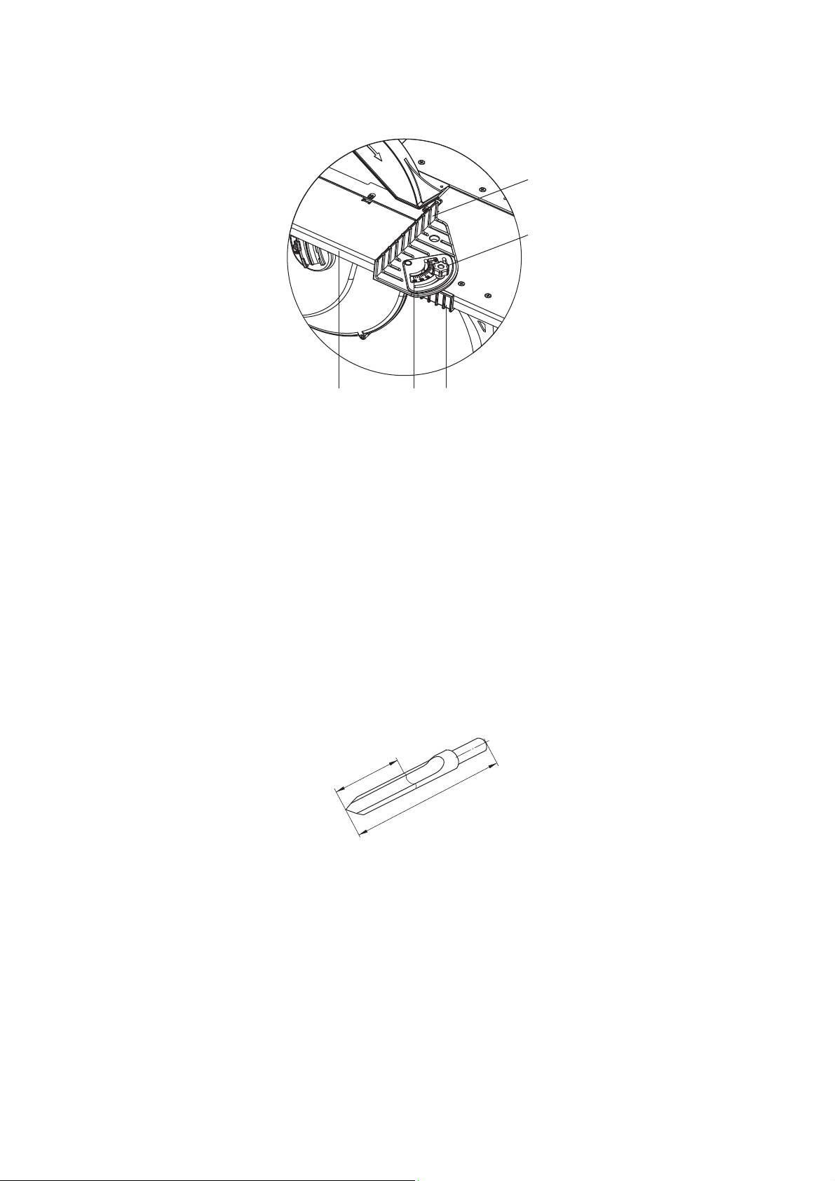
workpiece to the bump 34, move the device along the guideway 26a in the direction of the
saw blade.
34
36
26а 35
33
Fig. Т
The device construction for angular cross cutting
26а – leading edge; 33 – bump slide; 34 – bump; 35 – scale; 36 – flywheel for bump fixation
11.5 Milling with end cutters/drilling
Before starting, it is recommended to make the following adjustments:
To bring together the loading 2 and outfeed planing 3 tables, install them on the same
level with the cutting table 26 as described in the paragraph 11.2.1;
To lower the saw blade 25 to the lower position «min» on the cutting depth scale 37;
To install the cutting tool;
To adjust the table;
To install the ruler 12 with the angular bump 11.
11.5.1 Installing the end mill cutter/drill
End mill cutters are used as a cutting tool as shown in the Fig. U.
40 mm
70 mm
Fig. U
End mill cutter
To install end mill cutter/drill, it is required to perform the following:
To remove knife’s block fencing 65 (Fig. Е);
To install the drill chuck 55(Fig. V) on the cutting surface of the knife block end;
To install and fix the end cutter47 or drill to the drill chuck 55;
To install fencing 51 of the end cutter 47 and fix it with screws 64.
The end mill cutter fencing has a sprung security cap 51a, which moves into the casing when
pressing the workpiece on the cap in the axial direction, opening the working part of the end
mill 47.
27

When the drill chuck is removed, install the knife’s end block fencing 65 (Fig. E).
64
51 51a
55
47
12
16
11
50 46 49
Fig. V
The construction of the machine in the end milling mode
11 – angular bump; 12 – ruler; 16 – flywheel; 46 – milling table; 47 – end mill; 49 – lever-stick for lifting/lowering of
milling table; 50 – flywheels for milling table fixation; 51 – fencing of end milling cutter; 51а – protective cap;
55 – drill chuck; 64 – screws for fixing of end mill fencing
11.5.2 Adjusting the milling table
Adjust the table 46 (Fig. V) for height relative to the cutter 47. To do so, lower the flywheels 50.
Adjust the desired height by switching the lever-stick 49 up/down and tighten the flywheels 50.
11.5.3 Installing the ruler with angular bump
The workpiece feeding is performed manually along the table 46 (Fig. V). For parallel motion
use the ruler 12 with angular bump 11. The angular bump is fixed with the flywheels 16 to the
milling table 46 through the screwed holes in the table.
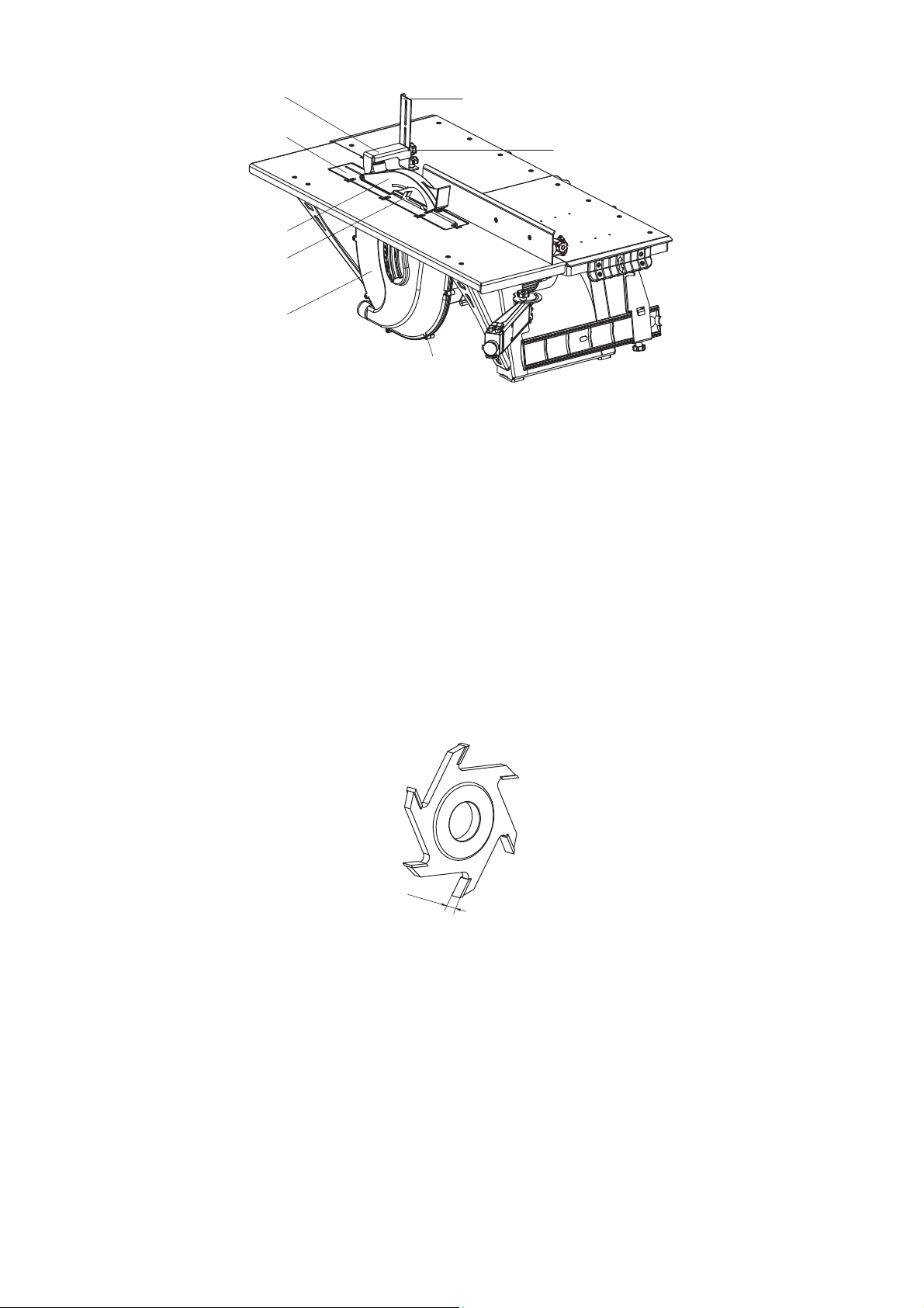
11.6 Milling with disc cutters
Before starting, it is recommended to make the following adjustments (Fig. W):
Install the disc cutter 40;
Install the fencing 29;
Adjust the milling depth.
28
42
41
31
29
40
30
30a
44
Fig. W
The structure of the machine in the milling with the cutter disk mode
29 – Fencing of saw blade/cutter above the table level; 30 – Fencing of saw blade/cutter below the table level;
30а – screws; 31 – cutting table insert; 41 – vertical rod of saw blade fencing; 40 – cutter disk; 42 – horizontal rod of
cutter disk fencing; 44 – flywheel for vertical rod fixation; 45 – insert for milling
11.6.1 Installing the cutter disc
It is recommended to use slot milling cutters for wood (Fig. X).
To install the disc cutter 40, perform the following actions:
remove the saw blade fencing 30, by loosening the screws 30а;
unscrew the lock nut of the saw blade 25 (Fig. В1, B2) with the help of a wrench 56;
remove the saw blade 25;
install the disc cutter 40, with it with the nut 67 backside;
install the insert 45;
install the cutter disc casing 30, fix it with the screws 30а.
10 mm
Fig. X
Slot milling cutter for wood
11.6.2 Installing the fencing
To install the fencing of the disc cutter 40 it is necessary to remove the fencing of saw blade
29 from the machine 25 with the help of the splitting knife 28.
It is necessary to install the vertical rod 41 in place of the splitting knife.
Fix the vertical rod with the fencing on the table with the flywheel 43.
Then adjust the insert 31 and fencing 29 position of the saw blade relative to the disc cutter
40. They should be installed symmetrically around the center of the disc cutter. The height of
29

the fencing is adjusted by moving the horizontal rod 42 along the vertical rod 41.
11.6.3 Adjusting the milling depth
The milling depth of the disc cutter is installed similarly as in the case of saw blade (p. 11.2.2).
The milling depth scale 38 is located from the right side of the casing 30 of the saw blade
(Fig. B).
12. MAINTENANCE AND REPAIR
In order to maintain the machine in a permanent technical efficient and working condition, it
is necessary to service the machine each time before using it. It includes the following:
Performing exterior check;
Checking the fixing security of slicing blades;
Cleaning the machine.
The exterior check includes cable test, integrity of security fencing test.
Checking the fixing security of slicing blades is performed by tightening the screws 71 with
the wrench (Fig.К).
Cleaning includes removing dust, cuttings, wood particles with a brush or a vacuum cleaner
from the machine surface.
12.1 Replacing the slicing blades
Periodically, it is required to resharpen or replace the slicing blades, whenever they has dulled
noticeably (Fig. Y).
The cutting edge of the blade should be sharp and clean. There should not be any notches,
rough guide lines and cracks.
70а 70а
40°± 5°
20
2
Fig. Y
Slicing blade
70a – slot
To the replace the knives, it is necessary to perform the following action:
remover the holder 69, by loosening the crews 71 (Fig. K);
replace the knife 70, installing it so that, the knife slots 70a fit the flags 73 (Fig. M);
install the holder 69 and fix it with the screws 71.
When installing the new blades, replacing fixing parts, and after resharpening, the difference
of the total mass of the knife kit with the fixing parts should not exceed 1 gram.
Adjust the knives as it is described in the paragraph 10.3.
30

12.2 Replacing the saw blade
It is recommended to apply the saw blades with carbide blades for this machine (Fig. Z).
ØD mm
2÷2,2mm
3,2mm
Ø32 mm
Fig. Z
Saw blade
When installing the saw blade it is necessary to observe the rotating direction. Installing
process is similar to the one described in the paragraph 11.6.1. The direction of the teeth
should coincide with the arrow direction on the security casing that protects the saw blade
above the work table.
12.2.1 Dismounting the saw blade/ cutter
Lower the saw blade 25 (cutter 40) with the help of the lever 27 (Fig. В2) to the down
position.
Unscrew the flywheel to fix the position of the saw blade/cutter 32.
Remove the cover of the saw blade (cutter) fencing 30with the help of the screw driver.
Install the flywheel 32 to its place.
Lift the saw blade/cutter to the uppermost position and fix it with the flywheel 32.
Put the wrench 68 into the gap between the saw blade/cutter and the insert hole of the
cutting table 31, fix the position of the flange of the saw blade/ cutter.
With the help of the box wrench 56, hold the wrench 68 unscrew the union joint of the nut 67
and flange of the saw blade/cutter.
Mind the left union joint of the nut 67. Tightening is performed counterclockwise,
loosening – clockwise.
Unfix the flywheel 32 and lower the saw blade/cutter to the down position.
Unscrew the flywheel 32.
Remove the nut 67 and the saw blade 25 (cutter 40).
12.2.2 Installing the saw blade/cutter
If necessary, clean all the parts before installation.
Install a new saw blade/cutter на on the bearing flange, set the nut 67.
Do not use saw blades of the smaller size. The distance between a saw blade and
a splitting knife should be up to 5 mm.
31
Make sure that the direction of the cutting teeth (arrow on the saw blade) coincided with
the direction of the arrow on the fencing of the saw blade 29.
Install the flywheel 32 and lift the saw blade / cutter in the uppermost position.
Fix the position with the flywheel 32.
Screw the nut 67 with the box wrench 56 holding the flange with the wrench 68.
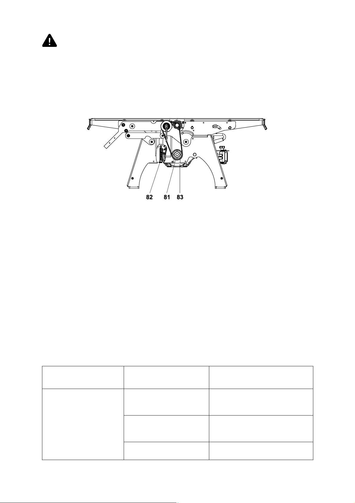
12.3 Replacing the drive belt
Fig. ZA
Installing the drive belt
81 – belt; 82 – spring; 83 – motor
To replace the drive belt, perform the following actions:
remove the saw blade as described in the paragraph11.6.1;
remove the back side of the casing 30 of the saw blade, by loosening the screws 30a with
a 3 mm hex wrench;
loosen the belt tension 82, by pushing the motor up 83, or by removing the tension spring
83;
install new belt;
assemble all the parts in reverse order.
The machine can be repaired only by a specialized enterprise.
13. TROUBLESHOOTING
The list of the possible malfunctions and troubleshooting methods is described in the Table 3.
Type of malfunction Probable reason Troubleshooting method
Check the main socket voltage
The machine connected
to the mains does not
operate
There is no supply voltage
There is no contact in the
outlet with the patch cable
plug
The switcher is broken
with other known-good,
household appliance
Correct the fault or replace the
plug
Replace the switcher at the
service center
Table 3
32

The continuous feed of the
process material should be
reduced
Install the knives and holding
element with the appropriate
weight, adjust their position
Restart the machine in 15-20 min.
Electric motor becomes
overheated
The motor operates but
the cutter block is not
rotating
The work machine
vibrates
The machine has
suddenly stopped during
operation
The machine is overloaded
because of the high-feed
operation
The wood material is wet Replace the workpiece
The belt is torn Replace the belt
The knives are incorrectly
matched and installed in
the improper way
The saw blade is deformed Replace the saw blade
There is no voltage Check the voltage
The thermal protection
shield was activated
14. STORAGE
Machines are designed for storage in closed or other naturally ventilated rooms without
artificially controlled climatic conditions where variations in temperature and air humidity is
substantially less than in the open air (such as stone, concrete, metal heat-insulated, and
other unheated warehouses, located in macroclimatic areas with moderate and frigid
climates).
It is necessary to pay attention to the labeling requirements on the individual packaging.
Keep the machine out of children’s reach.
15. TRANSPORTATION
The transportation of the machines is performed in closed vehicles.
The transportation of the machines is performed by two persons, holding the handles of the
package.
It is necessary to comply with the labeling requirements on individual packaging.
16. DISPOSAL
Never dispose this machine and its parts together with unsorted municipal waste.
The machine parts made of aluminum and plastics are labeled. That allows sorting and
recycling wastes.
Devices and tools of the machine, which have reached the end of their working life, must be
collected and disposed of separately from household waste material.
The list of the details, which do not meet the terms of this limited warranty:
saw blade;
belt;
slicing blades;
drill chuck;
plastic insert of the saw blade;
33

saw blade fencing;
end mill fencing.
The service life of the machine is no less than five years from the date of sale, under adherence
to the operating conditions and regular maintenance.
WARRANTY CERTIFICATE
Read this Warranty Certificate carefully; make sure that it is filled in.
Thoroughly check the product visual appearance and completeness. Claims on the visual
appearance and completeness shall be made immediately at the time of the product
acceptance.
If during the guarantee period any defects are detected, excluding the defects arising after
the handover of the products to the consumer due to violation of the transportation, storage
or use instructions by the latter, as well as actions of third parties or
one's reasonable control, we shall be obliged to satisfy the claims of the consumers in
conformity with the law and under the conditions as follows:
The product warranty period is 24 (twenty-four) months from the date of the sale of the
product by the trading organization.
This Warranty covers only the products used for private, household or domestic purposes,
unrelated to business activities.
Claims on the machine quality are accepted if the defects are detected within the warranty
period.
circumstances beyond
During the warranty period, the defects arising due to the fault of the manufacturing plant
shall be eliminated free of charge.
List of the machine damages, due to which the warranty obligations are cancelled:
disregard of operation instructions;
mechanical damage, damages caused by aggressive environments, high temperatures,
ingress of foreign bodies;
connection to the incorrect supply voltage;
damages arising due to the reasons beyond the manufacturer’s control: power line
instability;
the machine has been dismantled by the customer;
self-directed replacement of units and parts, the design change;
overload performance;
damages due to improper storage (metal parts corrosion), severe contamination and
negligent operation;
use of the machine for purposes other than intended;
damages due to the circumstances beyond one's reasonable control (accident, fire, flood,
lightning stroke, etc.).
List of the parts not covered by the Warranty:
circular saw blade;
strap;
planer knives;
drill chuck;
saw table plastic insert;
34

circular saw blade locking;
end-milling cutter locking.
The machine operating life is no less than five years from the date of sale by the trading
organization, if the working conditions requirements are observed and the maintenance
procedures are carried out regularly.
The Service Department is ready to answer all the questions regarding the repair and
maintenance of the machines, as well as regarding the spare parts. See the full information on
www.belmash.by.
The manufacturer’s address:
Zavod Belmash, JLLC, 212000, 37, Slavgorodskiy Proezd, Mogilev, Republic of Belarus.
E-mail: info@belmash.by.
35

36
 Loading...