

Page 1
工程出图章
2016.05.20
工程部
正式发行
2016.05.20
工程部
Page 2
工程出图章
2016.05.20
工程部
正式发行
2016.05.20
工程部
Page 3
PRODUCT SPECIFICATION
B.1
201
7 / 02/ 07
Kevin Miao
Ivanov
Wang
Ivanov
Wang
PRODUCT DESCRIPTION:
MICRO-HI POWER CONNECTOR
PRODUCT NUMBER:
PCB SIDE:
70094 SERIES
70095 SERIES
70096 SERIES
HOUSING FOR CABLE SIDE:
70093 SERIES
70189 SERIES
TERMINAL FOR CABLE SIDE:
70097 SERIES
REVISION: ECR/ECN NUMBER: DOCUMENT NUMBER
DATE: CREATED / REVISED BY: CHECKED BY: APPROVED BY:
EK2017-0028
PS-70094-001
SHEET No.
1 of 11
Form No.: QR-QP025-15 REV.: A
Page 4
PRODUCT SPECIFICATION
B.1
201
7 / 02/ 07
Kevin Miao
Ivanov
Wang
Ivanov
Wang
1.0 SCOPE..................................................................................................….................3
2.0 APPLICABLE DOCUMENTS……………………………............…..…........................3
3.0 CONSTRUCTION AND MATERIAL..........................................................................3
4.0 RATINGS……………………………………….........….…….........................................3
5.0 PERFORMANCE, TEST REQUIREMENT AND PROCEDURES SUMMARY.……..5
6.0 TESTING SEQUENCE……… ..…………………………………..……………………8
7.0 OTHER INFORMATION ..…………………………………..……………………………10
REVISION: ECR/ECN NUMBER: DOCUMENT NUMBER
DATE: CREATED / REVISED BY: CHECKED BY: APPROVED BY:
EK2017-0028
PS-70094-001
SHEET No.
2 of 11
Form No.: QR-QP025-15 REV.: A
Page 5
B.1
201
7 / 02/ 07
Kevin Miao
Ivanov
Wang
Ivanov
Wang
1.0 SCOPE
headers when mated with either printed circuit board (PCB) connector.
PRODUCT SPECIFICATION
This Product Specification covers the 3.00 mm (.118 inch) centerline (pitch) square pin
2.0 APPLICABLE DOCUMENTS
The following documents form a part of this specification to the extent specified herein. In the
event of conflict between the requirements of this specification and the product drawing, the
product drawing shall take precedence. In the event of conflict between the requirements of this
specification and the referenced documents, this specification shall take precedence.
EIA-364
UL Safety Agency Approval File Numbers: E346898
3.0 CONSTRUCTION AND MATERIAL
Housings:
LCP (Header);
Nylon (Receptacle);
Header Terminal:
Copper Alloy
Receptacle Terminal:
Copper Alloy
4.0 RATINGS
4.1 UL Safety Agency Ratings
Agency Voltage Rating: 600V (AC/DC)
Agency Current Rating: 12.5A (Single Circuit) (Amps)
4.2 VOLTAGE RATING: 600V
REVISION: ECR/ECN NUMBER: DOCUMENT NUMBER
EK2017-0028
DATE: CREATED / REVISED BY: CHECKED BY: APPROVED BY:
PS-70094-001
SHEET No.
3 of 11
Form No.: QR-QP025-15 REV.: A
Page 6
PRODUCT SPECIFICATION
B.1
201
7 / 02/ 07
Kevin Miao
Ivanov
Wang
Ivanov
Wang
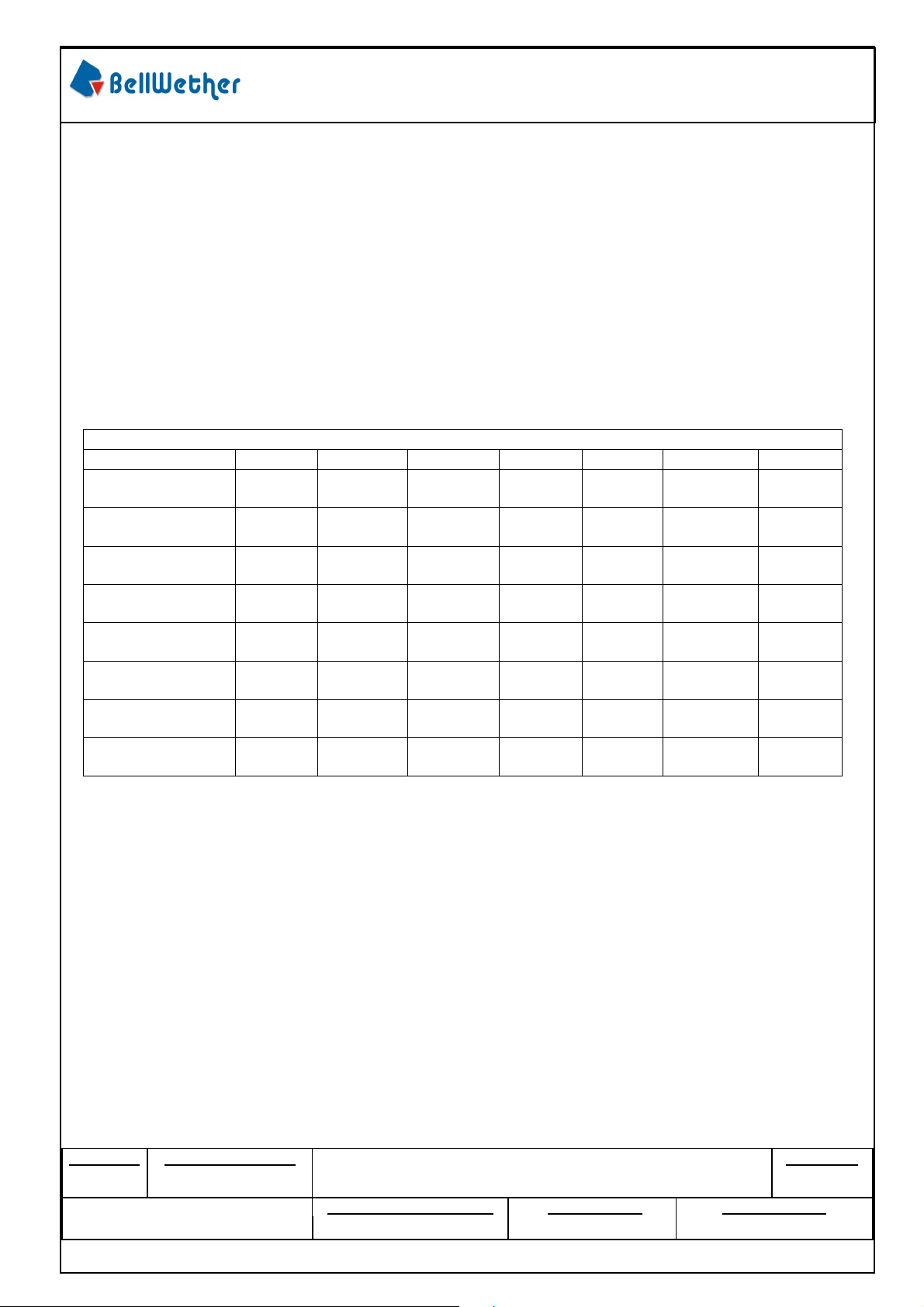
4.3 CURRENT DERATING AND APPLICABLE WIRES
Current is dependent on connector size, contact material, plating, ambient temperature, printed
circuit board characteristics and related factors. Actual current rating is application dependent and
should be evaluated for each application.
AWG Outside Insulation Diameter
16 2.40 mm
18 2.10 mm
20 1.85 mm
22 1.85 mm
24 1.85 mm
26 1.27 mm
28 1.27 mm
30 1.27 mm
CURRENT DERATING REFERENCE INFORMATION (A/PER PIN)
Circuit Size 2 4 6,8 10 12 14,16,18 20,22,24
16 AWG
(A/PER PIN)
18 AWG
(A/PER PIN)
20 AWG
(A/PER PIN)
22 AWG
(A/PER PIN)
24 AWG
(A/PER PIN)
26 AWG
(A/PER PIN)
28 AWG
(A/PER PIN)
30 AWG
(A/PER PIN)
1) Values are for reference only.
2) Current deratings are based on not exceeding 30°C Temperature Rise.
3) PCB trace design can greatly affect temperature rise results in Wire-to-Board applications.
4) Data is for all circuits powered.
5) * indicates interpolated information.
4.4 Service temperature: -40°C to 105°C;Storage temperature: -40°C to 105°C
12.5A 12A 10.5A 10.5A 9.0A 8.5A 8.0A
10.5A 9.5A 8.5A 8.0A 8.0A 7.5A 7.0A
9.0A 9.0A 7.0A 6.5A 6.5A 6.0A 5.5A
6.0A 5.0A 4.5A 4.0A 4.0A 3.5A 3.5A
5.5A 5.0A 4.5A 4.0A 3.5A 3.5A 3.0A
4.5A 4.0A 4.0A 3.5A 3.5A 3.0A 2.5A
4.0A 3.5A 3.0A 3.0A 3.0A 2.5A 2.0A
3.5A 3.0A 3.0A 2.5A 2.5A 1.5A 1.0A
REVISION: ECR/ECN NUMBER: DOCUMENT NUMBER
DATE: CREATED / REVISED BY: CHECKED BY: APPROVED BY:
EK2017-0028
PS-70094-001
SHEET No.
4 of 11
Form No.: QR-QP025-15 REV.: A
Page 7
PRODUCT SPECIFICATION
B.1
201
7 / 02/ 07
Kevin Miao
Ivanov
Wang
Ivanov
Wang
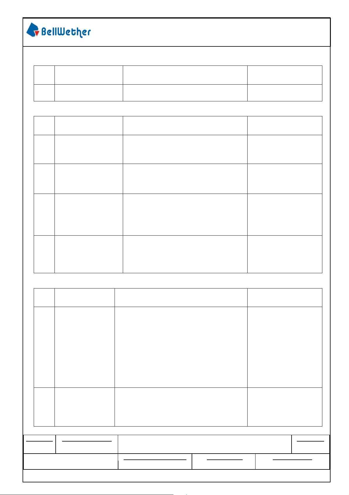
5.0 PERFORMANCE, TEST REQUIREMENT AND PROCEDURES SUMMARY
5.1 APPEARANCE REQUIREMENTS
Item Test Description Test Method
1
5.2 ELECTRICAL REQUIREMENTS
Examination of
product
Item Test Description Test Method
Visual according to applicable quality
inspection plan.
Reference
Standard
Meet the requirements
of product
Reference
Standard
Contact
2
3
4
5 Temperature Rise
5.3 MECHANICAL REQUIREMENTS
Item
6
Resistance
(Low Level)
Insulation
Resistance
Dielectric
Withstanding
Voltage
Test
Description
Connector Mate
And
Unmate Forces
Mate connectors: apply a maximum
voltage of 20 mV and a current of 100
mA. (Does not include wire resistance)
Unmate & unmount connectors: apply a
voltage of 500 VDC between adjacent
terminals and between terminals to
ground.
Unmate connectors: apply a voltage of
{two times the rated voltage plus 1000
volts} VAC for 1 minute between
adjacent terminals and between
terminals to ground.
Mate connectors, measure the
temperature rise at the rated current.
The ambient condition is still air at 25°C,
Per EIA-364-70 method 2.
Test Method
Mate and unmate connector (male to
female) at a rate of 25 ± 6 mm per minute.
(Per circuit)
5 milliohms MAXIMUM
[initial]
1000 Megohms
MINIMUM
No breakdown;
current leakage < 5 mA
Temperature rise:
+30°C MAXIMUM
Reference
Standard
8.0 N (1.8 lbf)
MAXIMUM insertion
force & 2.0 N (0.45lbf)
MINIMUM withdrawal
force (Tin plated)
5.6 N (1.26 lbf)
MAXIMUM insertion
force & 1.5 N (0.34lbf)
MINIMUM withdrawal
force (Gold plated)
REVISION: ECR/ECN NUMBER: DOCUMENT NUMBER
DATE: CREATED / REVISED BY: CHECKED BY: APPROVED BY:
7
Terminal
Retention Force
(in Housing)
EK2017-0028
Axial pullout force on the terminal in the
housing at a rate of 25 ± 6 mm per minute.
PS-70094-001
24.5 N (5.5 lbf)
MINIMUM retention
force
SHEET No.
5 of 11
Form No.: QR-QP025-15 REV.: A
Page 8
PRODUCT SPECIFICATION
B.1
201
7 / 02/ 07
Kevin Miao
Ivanov
Wang
Ivanov
Wang
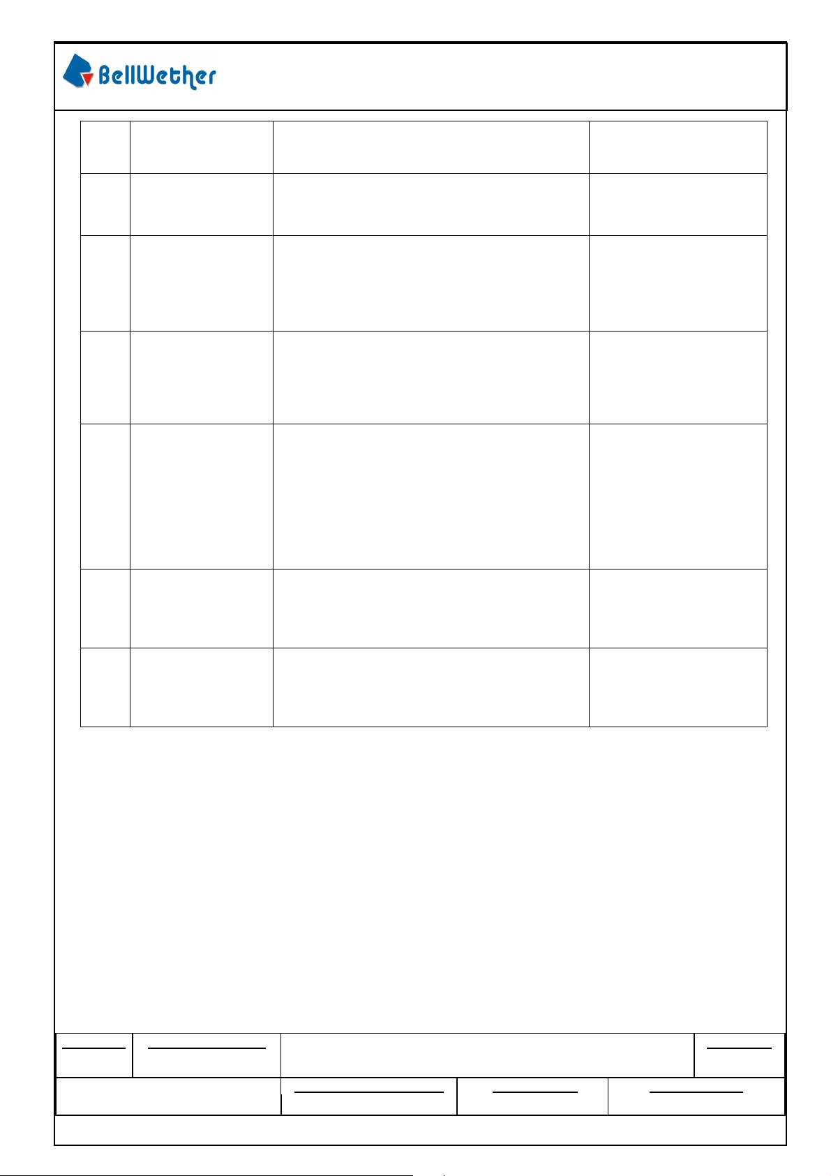
Terminal
14.7 N (3.3 lbf)
MAXIMUM insertion
force
6 milliohms MAXIMUM
8
9
Insertion Force
(into Housing)
Durability
Apply an axial insertion force on the
terminal at a rate of 25 ± 6 mm per minute.
Mate connectors up to 30 cycles at a
maximum rate of 10 cycles per minute prior
to Environmental Tests.
10
11
12
13
14
Vibration
(Random)
Shock
(Mechanical)
Wire Pullout Force
(Axial)
(Wire from
Terminal)
Pin to Header
Retention
Thumb Latch to
Ramp Yield
Strength
Mate connectors and vibrate per EIA 36428,test condition VII, Letter D. Test
Duration: 15 minutes each axis.
Mate connectors and shock at 50 g’s with
½ sine wave (11 milliseconds) shocks in the
±X,±Y,±Z axes (18 shocks total).
Apply an axial pullout force on the wire at a
rate of 25 ± 6 mm per minute.
Apply axial push force to pin at a rate of 25
±6 mm per minute.
Full mate and then Unmate the connectors
at a rate of 25 ± 6 mm per minute.
6 milliohms MAXIMUM
& Discontinuity < 1
microsecond
6 milliohms MAXIMUM
& Discontinuity < 1
microsecond
MINIMUM pullout force
16 Awg: 88.0 N (19.8 lbf)
18 Awg: 88.0 N (19.8 lbf)
20 Awg: 57.8 N (13.0 lbf)
22 Awg: 35.5 N (8.0 lbf)
24 Awg: 26.6 N (6.0 lbf)
26 Awg: 13.3 N (3.0 lbf)
28 Awg: 8.9 N (2.0 lbf)
30 Awg: 6.6 N (1.5 lbf)
13.7 N (3.1 Ibf)
MINIMUM pushout
force
45 N (10.125 lbf)
MINIMUM Yield
Strength
REVISION: ECR/ECN NUMBER: DOCUMENT NUMBER
EK2017-0028
DATE: CREATED / REVISED BY: CHECKED BY: APPROVED BY:
PS-70094-001
Form No.: QR-QP025-15 REV.: A
SHEET No.
6 of 11
Page 9
PRODUCT SPECIFICATION
B.1
201
7 / 02/ 07
Kevin Miao
Ivanov
Wang
Ivanov
Wang
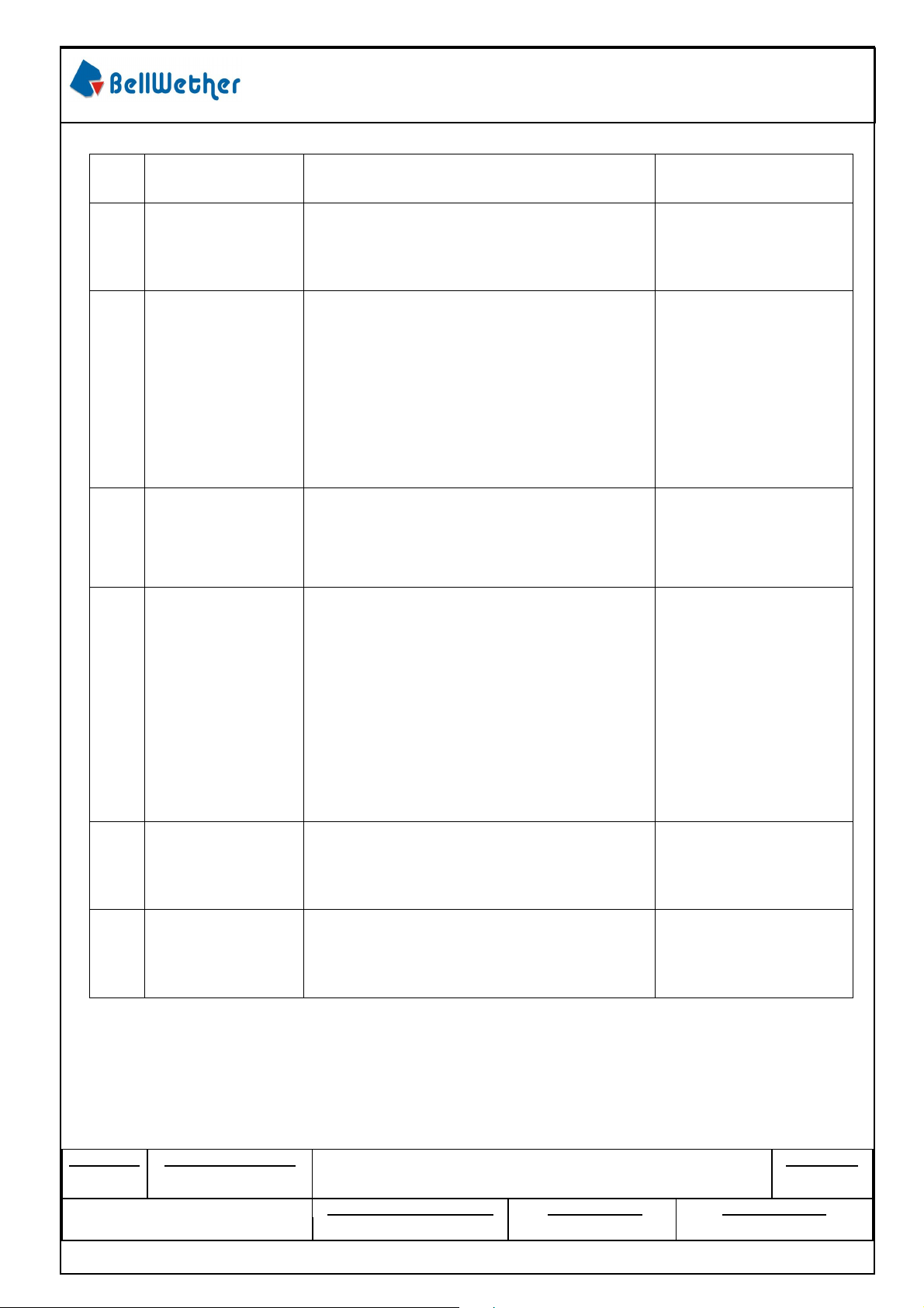
5.4 ENVIRONMENTAL REQUIREMENTS
Item
15
16
17
18
Test
Description
Thermal Aging
Humidity
(Steady State)
Solder ability
Solder Resistance
Test Method
Mate connectors; expose to:
240 hours at 105 ± 2°C or 500 hours at
85 ± 2°C
Mate connectors: expose to a temperature
of 40 ± 2°C with a relative humidity of 9095% for 96 hours.
Note: Remove surface moisture and air dry
for 1 hour prior to measurements.
Immerse the solder pin of the connector in
the solder bath at 260°C +/-5°C for 5+/-0.5
seconds After dipped the pin in the flux of
RAM or R type for 5 seconds MIL-STD-202
METHOD 208
A) Wave Solder Process
Dip connector terminal tails in solder;
Solder Duration: 10 seconds MAX
Solder Temperature: 260°C MAX
B) Convection Reflow Solder Process
235°C MAX
Parts identified with a green dot on the
primary shipping carton label and all parts
with a manufacturing date after 11/1/2007:
260°C MAX
Reference
Standard
6 milliohms MAXIMUM
6 milliohms MAXIMUM
&
Dielectric Withstanding
Voltage:
No Breakdown at 500
VAC
&
Insulation Resistance:
1000 Megohms
MINIMUM
Solder coverage:
95% MINIMUM
Visual :No Damage to
insulator material
REVISION: ECR/ECN NUMBER: DOCUMENT NUMBER
DATE: CREATED / REVISED BY: CHECKED BY: APPROVED BY:
19
20
Cold Resistance
Thermal Shock
EK2017-0028
Mate connectors:
Duration: 96 hours;
Temperature: -40 ± 3°C
Test cycles: 5cycles
Temperature range :
-55±3°C→30 minute
85±2°C→30 minute
PS-70094-001
6 milliohms MAXIMUM
No Damage
SHEET No.
7 of 11
Form No.: QR-QP025-15 REV.: A
Page 10
B.1
201
7 / 02/ 07
Kevin Miao
Ivanov
Wang
Ivanov
Wang
Dielectric
Connector Mate
Terminal
Insertion
Wire Pullout Force
Pin to Header
Thumb Latch to
Humidity
(Steady
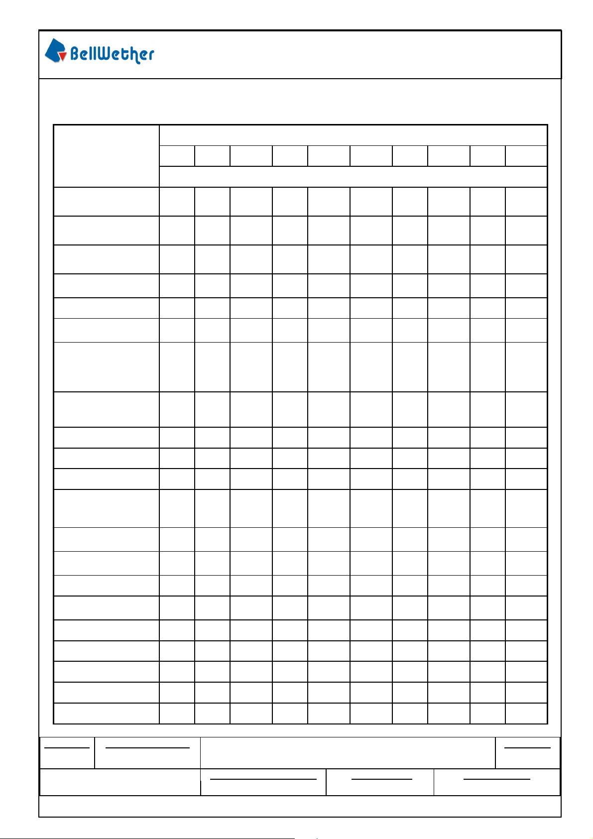
6.0 TESTING SEQUENCE
6.1 TEST GROUP
PRODUCT SPECIFICATION
Test of
Examination
Examination of
Product
Low Level Contact
Resistance
Insulation
Resistance
Withstanding Voltage
Temperature Rise
And Unmate Forces
Terminal
Retention
Force
(in Housing)
Force
(into Housing)
Durability
Test Group
A B C D E F G H I J
Test Sequence
1 1 1,4,6
2,4,6 2,4,6
10 2,4 4 2,5
1,7 1 1 1 1 1 1
2, 8
3, 9
2
3
3
2
4
Vibration (Random)
Shock (Mechanical)
(Axial)
(Wire from Terminal)
Retention
Ramp Yield Strength
Thermal Aging
State)
Solder ability
Solder Resistance
Cold Resistance
Thermal Shock
Sample size
REVISION: ECR/ECN NUMBER: DOCUMENT NUMBER
EK2017-0028
DATE: CREATED / REVISED BY: CHECKED BY: APPROVED BY:
3
5
2
2
2
3
5 7
5
6
3
3 5
5 5 5 5 5 5 5 5 5 5
SHEET No.
PS-70094-001
8 of 11
Form No.: QR-QP025-15 REV.: A
Page 11
PRODUCT SPECIFICATION
B.1
201
7 / 02/ 07
Kevin Miao
Ivanov
Wang
Ivanov
Wang
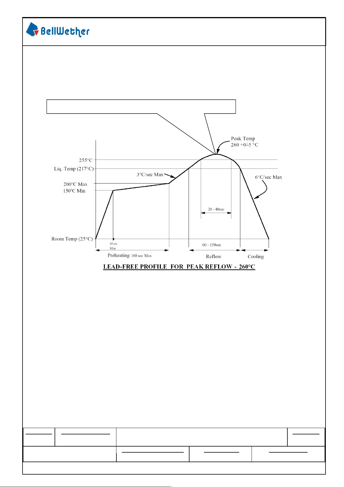
6.2 IR PROFILE
Recommended Reflow Pre-Solder Process and Profile.
Actual reflow profile also depends on equipment, solder paste, PCB thickness, and other
components on the board. Please consult your solder paste & reflow equipment manufacturer for
their recommendations to adopt a suitable process.
260°C Max 10 second/cycles 2 cycles(Peak Temperature)
Notes :
1. Reflow solder preheat at 3°C/s to 150°C.
2. Reflow at 255°C for 30s per figure.
3. Peak temperature to be at 260 +0/-5°C.
REVISION: ECR/ECN NUMBER: DOCUMENT NUMBER
EK2017-0028
DATE: CREATED / REVISED BY: CHECKED BY: APPROVED BY:
PS-70094-001
SHEET No.
9 of 11
Form No.: QR-QP025-15 REV.: A
Page 12
PRODUCT SPECIFICATION
B.1
201
7 / 02/ 07
Kevin Miao
Ivanov
Wang
Ivanov
Wang
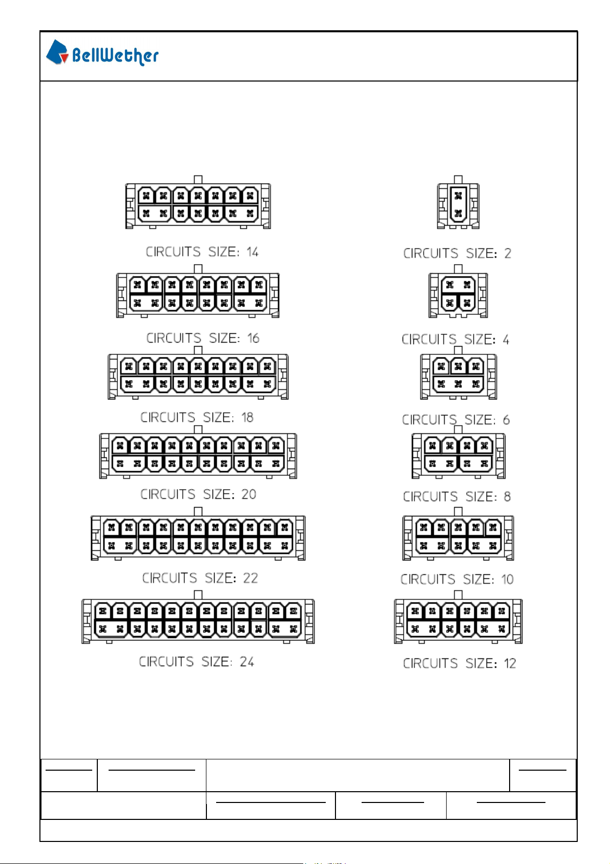
7.0 OTHER INFORMATION
7.1 STANDARD POLARIZATION FOR HEADERS
REVISION: ECR/ECN NUMBER: DOCUMENT NUMBER
DATE: CREATED / REVISED BY: CHECKED BY: APPROVED BY:
EK2017-0028
PS-70094-001
SHEET No.
10 of 11
Form No.: QR-QP025-15 REV.: A
Page 13
PRODUCT SPECIFICATION
B.1
201
7 / 02/ 07
Kevin Miao
Ivanov
Wang
Ivanov
Wang
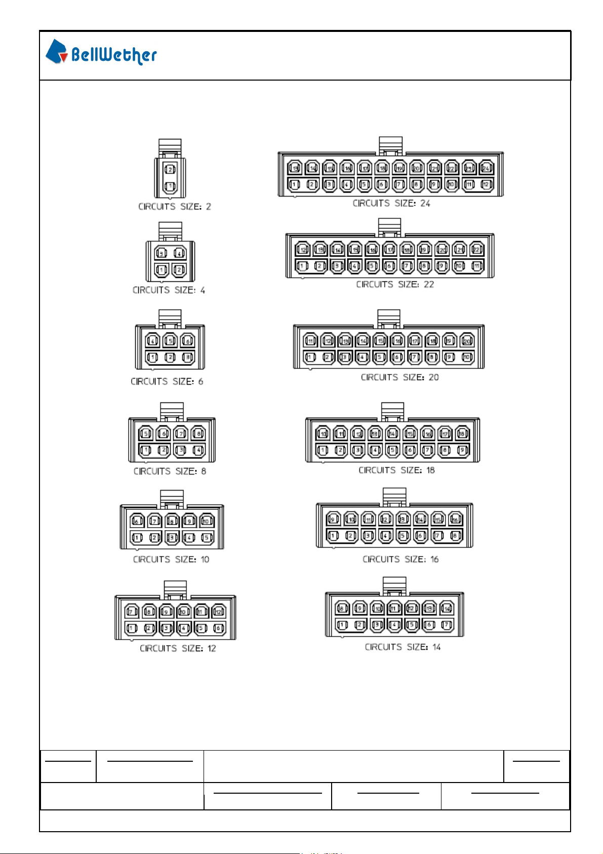
7.2 STANDARD POLARIZATION FOR RECEPTACLES
REVISION: ECR/ECN NUMBER: DOCUMENT NUMBER
DATE: CREATED / REVISED BY: CHECKED BY: APPROVED BY:
EK2017-0028
PS-70094-001
SHEET No.
11 of 11
Form No.: QR-QP025-15 REV.: A
 Loading...