

Bellofram Air Regulators Type 10, Air Regulators Type 110, Air Regulators Type 40, Air Regulators Type 41, Air Regulators Type 50 Catalog
...Page 1
Air
Regulators
Type 10
Type 110
Type 40
Type 41
Type 50
Type 50 NACE
Type 51
Type 51SS
Air Regulators
Type 60
Type 65
Type 70
Type 70BP
Type 77
Type 78
Type 91
Type 92
Type M1
Type M2
www.marshbellofram.com • 800.727.5646
1
Page 2
Air Regulators
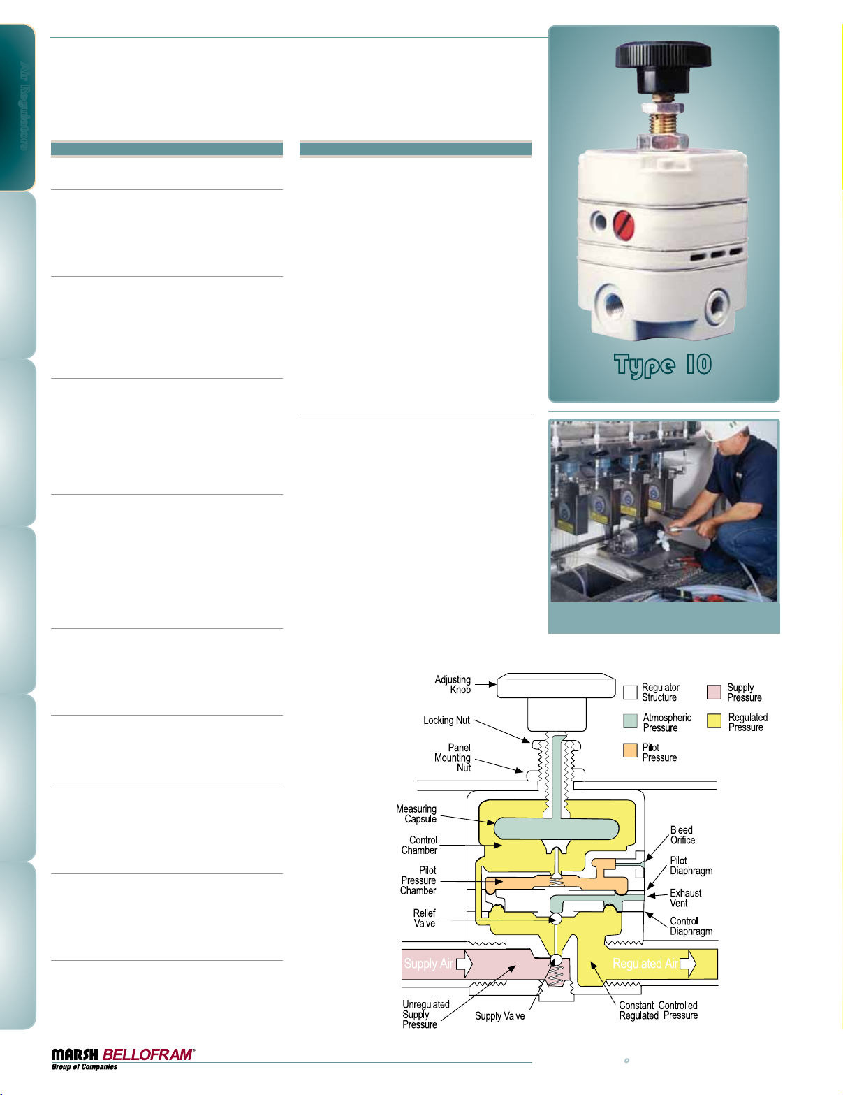
Type 10
Pressure Regulator Series
Features
Highly Accurate
Pressure Regulation
The Bellofram Type 10 Regulator controls
output pressure with an accuracy of 0.1%,
and has very low sensitivity to changes in
supply pressure and flow.
Start-Up Stability
The Type 10 Regulator has been designed to
eliminate the need for any readjustment of the
regulated pressure after long “down time.”
At start-up, the regulated pressure will return
to its output setting.
Flow Stability
The regulated pressure is held constant over
substantial changes in flow due to the high-gain
pneumatic servo amplifier. Particularly good
from dead end to 20 cubic meters per hour
(12 SCFM).
Automatic High
Downstream Relief Capacity
An integral relief valve provides for exhaust
flow whenever the regulated pressure is reset
to a lower value. The exceptionally large
capacity of this relief valve assures immediate response when the downstream regulated
pressure must be reduced under dead-end
conditions.
Pressure Stability
A high performance servo-operated control
mechanism is utilized in the regulator. The
pressure supplied to the pneumatic servo
amplifier is reduced and held constant.
Locking Capability
The standard Type 10 regulator has a locking
nut which, when tightened, prevents inadvertent adjustment of pressure.
Temperature Stability
Shifts in the regulated pressure over wide
ambient temperature variations are minimized
by the use of a measuring capsule made of
specially selected stainless steel alloys.
Proven Reliability
Thousands of Type 10 Regulators are in the field.
Proof of the accuracy of the regulator is reflected
by its use in most air gauging systems and other
precision pressure control applications.
Mounting
The unit may be installed in any position.
It can be panel mounted or supported by in-line
plumbing.
Applications
Industrial processes, inspection procedures,
control and analytical instrumentation require
precise regulation of air pressure in pipes and
vessels. Maintaining constant pressures in
these applications is usually complicated by
the presence of numerous disturbances, such
as changes in supply pressure, flow, and ambient temperature, that tend to upset prevailing
conditions.
Bellofram Pressure Regulators provide accuracy,
precision control, and maximum stability under
the most adverse operating conditions.
Type 10 Pressure
Regulator Applications
•Gas Mixing
•Valve Operators
•Gate Actuators
•Positioner Signal
•Calibration Stands
•Air Hoists
•Air Gauging
•Cylinder Loading
•Force Balance Hoists
•Disc and Shoe Air Brakes
•Clamp Units
•Web Tensioning
•Press Units
•Roll Loading
Type 10
Pressure Regulator Series
2
800.727.5646 • www.marshbellofram.com
Page 3
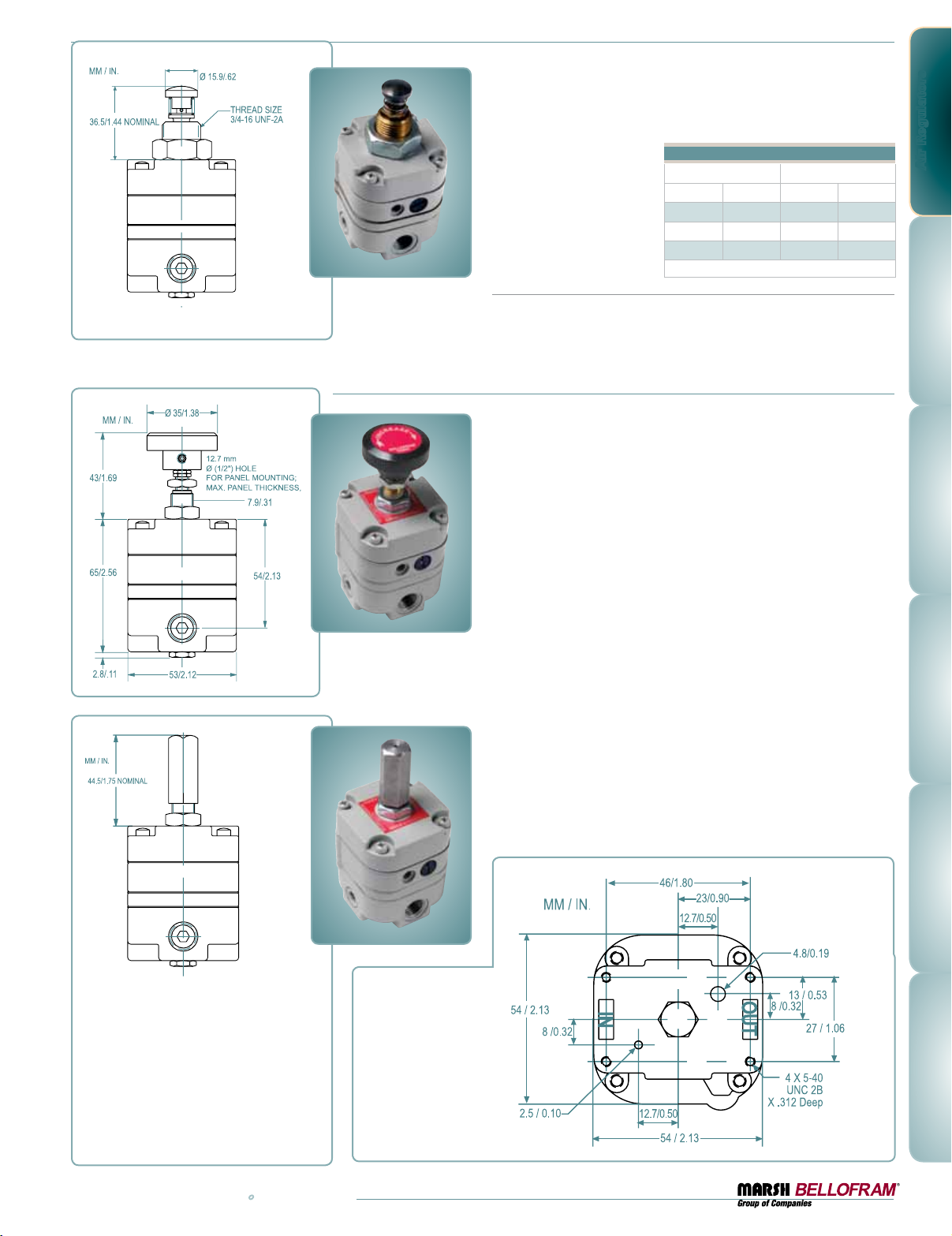
Type 10PL
Plunger Operated Regulator
Plunger
This reliable plunger operated
regulator provides unmatched
accuracy and repeatability.
Regulated pressure is changed
by direct linear actuation of
the plunger instead of turning
a knob.
Return Spring
0.4 in. (10mm) nominal return height; 7 oz. (200g) approximate preload
force; 7.5 lb./in. (135g/mm) approximate spring rate, between 0.4 in.
(10mm) and 0.24 in. (6.5mm) compressed height.
Plunger Knob Material: Steel
The basic Type 10 Regulator is offered with a choice of three port sizes
and three output ranges.
Plunger Travel
Pressure Range Plunger Travel*
BAR psig mm inch
0.1–1.7 2-25 1. 9 .075
0.1–4.1 2-60 2.3 .090
0.1–8.3 2-120 2.5 .100
*±10% manufacturing tolerance
Type 10HR & 10EXHR
High Relief Regulators
Similar in proven accuracy and rugged construction to other Type 10
Regulators, these units provide extra fast “blowdown” for very rapid
release of down stream pressure. The extra relief feature makes these
regulators suitable for cylinder return stroke actuation, air hoists, and
similar applications requiring fast exhaust.
Air Regulators
Knob
Tamper Resistant
The Type 10 Regulator is available with
a tamper resistant cover, as illustrated.
The cover is threaded over the adjusting
screw to prevent inadvertent or unwarranted adjustment of output pressure.
Type 10LR
Low Range Regulator
The main feature of the Type 10LR is its low-range pressure characteristic. It operates on a maximum of 50 psig / 3.4 BAR supply pressure and offers an output pressure range of 0.5 psig / 0.03 BAR to 25 psig / 1.7 BAR
The Type 10 Regulator
is also available with
bottom ports,
(Type 1 0BM)
consult factory.
www.marshbellofram.com • 800.727.5646
3
Page 4
Air Regulators
Maximum
Supply Pressure
Pressure Ranges
Port Sizes
Effect of Supply
Pressure Variation
on Outlet Pressure
Sensitivity
Bleed Rate
Forward Flow Capacity
Exhaust Capacity
@ 5 psig (0.4 BAR)
above setpoint
Temperature Range
Effect of Changes in
Flow on Regulated
Pressure
Type 10LR Type 10 / 10PL Type 10 BM Type 10HR Type 10 EXHR Type 10 HF Type 10 Motorized
50 psig / 3.4 BAR 150 psig / 10.3 BAR 150 psig / 10.3 BAR 150 psig / 10.3 BAR 150 psig / 10.3 BAR 50 psig / 3.4 BAR 150 psig / 10.3 BAR
.5-25 psig
0.03 – 1.7 BAR
1/4 1/8, 1/4, 3/8 N/A 1/8, 1/4, 3/8 1/8, 1/4, 3/8 3/8 1/8, 1/4, 3/8
0.005 psig /
0.3 mBAR
per 25 psig /
1.7 BAR change
1/8" / 3.2mm
of water
4.8 scfh / 2.3 LPM 4.8 scfh / 2.3 LPM 4.8 scfh / 2.3 LPM 4.8 scfh / 2.3 LPM 4.8 scfh / 2.3 LPM 4.8 scfh / 2.3 LPM 4.8 scfh / 2.3 LPM
4 scfm / 113 LPM 14 scfm / 396 LPM 3 scfm / 85 LPM 14 scfm / 396 LPM 14 scfm / 396 LPM 40 scfm / 1132 LPM 10 scfm / 283 LPM
2 scfm / 56 LPM 2 scfm / 56 LPM 2 scfm / 56 LPM 10 scfm / 283 LPM 15 scfm / 424 LPM 2 scfm / 56 LPM 2 scfm / 56 LPM
-20 to 160˚F
-29 to 71˚C
N/A
2-25, 2-60, 2-120 psig
0.14–1.7, 0.14–4.1,
0.14–8.3 BAR
0.005 psig /
0.3 mBAR
per 25 psig /
1.7 BAR change
1/8" / 3.2mm
of water
-20 to 160˚F
-29 to 71˚C
0.25 psig / 0.01 BAR
per 10 scfm /
283 LPM
2-25, 2-60, 2-120 psig
0.14–1.7, 0.14–4.1,
0.14–8.3 BAR
0.005 psig /
0.3 mBAR
per 25 psig /
1.7 BAR change
1/8" / 3.2mm
of water
-20 to 160˚F
-29 to 71˚C
N/A
2-120 psig
0.14–8.3 BAR
0.005 psig /
0.3 mBAR
per 25 psig /
1.7 BAR change
1/8" / 3.2mm
of water
-20 to 160˚F
-29 to 71˚C
0.25 psig / 0.01 BAR
per 10 scfm /
283 LPM
2-120 psig
0.14–8.3 BAR
0.005 psig /
0.3 mBAR
per 25 psig /
1.7 BAR change
1/8" / 3.2mm
of water
-20 to 160˚F
-29 to 71˚C
0.25 psig / 0.01 BAR
per 10 scfm /
283 LPM
2-25 psig
0.14–1.7 BAR
0.005 psig /
0.3 mBAR
per 25 psig /
1.7 BAR change
1/8" / 3.2mm
of water
-20 to 160˚F
-29 to 71˚C
0.25 psig / 0.01 BAR
per 10 scfm / 283
LPM
0.5-25, 2-25, 2-60,
2-120 psig
0.03–1.7, 0.14–1.7,
0.14–4.1, 0.14–4.1,
0.14–8.3 BAR
0.005 psig /
0.3 mBAR
per 25 psig /
1.7 BAR change
1/8" / 3.2mm
of water
0 to 140˚F
-18 to 60˚C
0.25 psig / 0.01 BAR
per 10 scfm / 283 LPM
BAR psig
3.46 50.1
3.45 50.0
3.44 49.9
3.43 49.8
3.42 49.7
SCFM 0 1.7 3.4 5.1 6.8 8.5 10.2 11. 9 13.6 15.3 17. 0
m3/hr 0 1 2 3 4 5 6 7 8 9 10
2.08 30.1
2.07 30.0
2.06 29.9
2.05 29.8
Regulated PRessuRe
2.0 29.7
SCFM 0 1.7 3.4 5.1 6.8 8.5 10.2 11. 9 13.6 15.3 17. 0
m3/hr 0 1 2 3 4 5 6 7 8 9 10
0.70 10.1
0.69 10.0
0.683 9.9
0.68 9.8
0.67 9.7
SCFM 0 1.7 3.4 5.1 6.8 8.5 10.2 11. 9 13.6 15.3 17. 0
m3/hr 0 1 2 3 4 5 6 7 8 9 10
Range
0.1–8.3 BAR
2–120 psig
Supply
6.2 BAR
90 psig
Range
0.1–4.1 BAR
2–60 psig
Supply
6.2 BAR
90 psig
Range
0.1–1.7 BAR
2–25 psig
Supply
6.2 BAR
90 psig
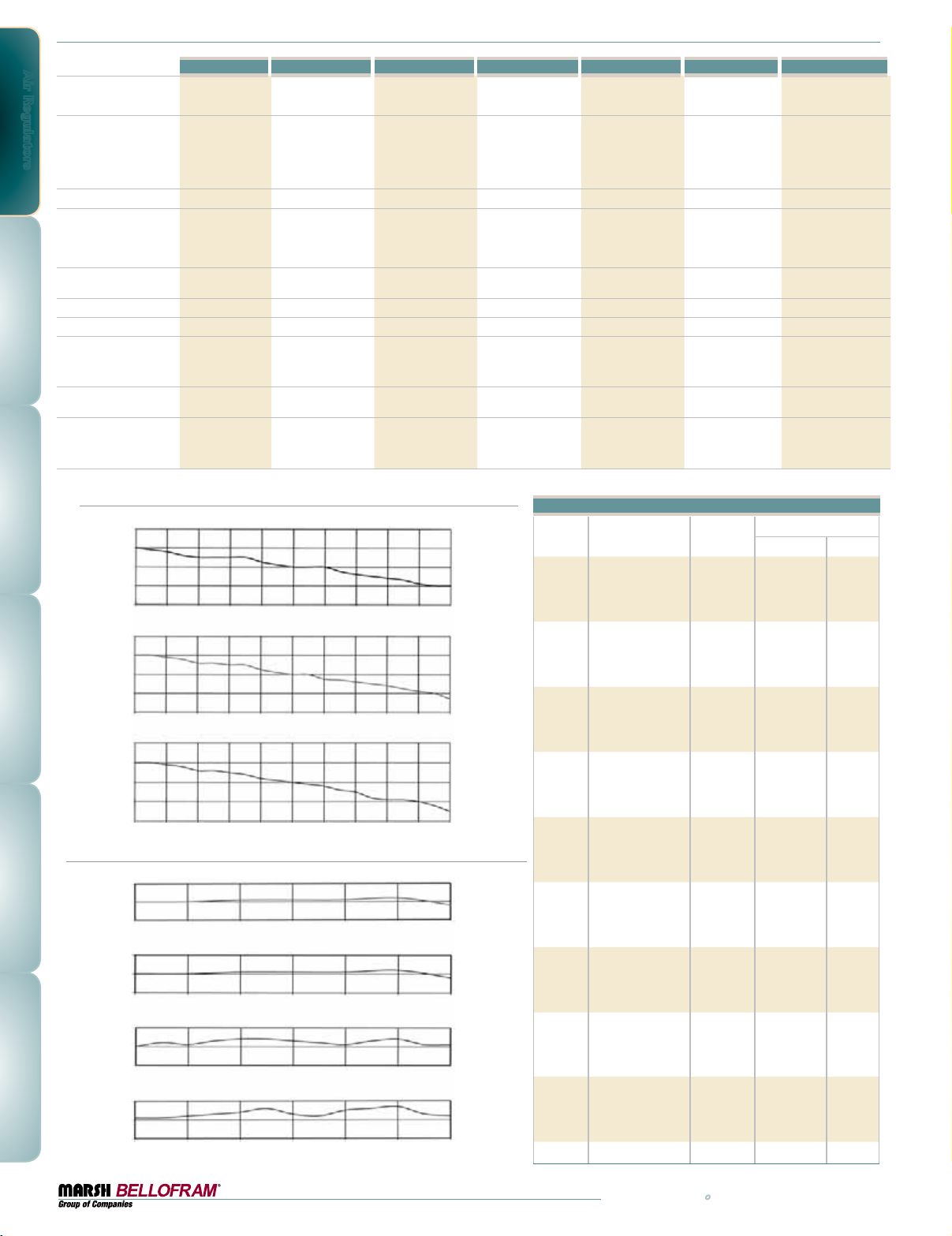
Effect of Upstream Pressure Variations on Regulated Pressure
Effect of Changes in Flow on Regulated Pressure
BAR psig
0.70 10.1
0.69 10.0
0.68 39.9
BAR 2.76 3.45 4.14 4.83 5.52 6.21 6.9
psig 40 50 60 70 80 90 10 0
0.70 10.1
0.69 10.0
0.683 9.9
BAR 2.76 3.45 4.14 4.83 5.52 6.21 6.9
psig 40 50 60 70 80 90 10 0
0.70 10.1
0.69 10.0
Regulated PRessuRe
0.683 9.9
BAR 2.76 3.45 4.14 4.83 5.52 6.21 6.9
psig 40 50 60 70 80 90 10 0
0.70 10.1
0.69 10.0
0.683 9.9
BAR 2.76 3.45 4.14 4.83 5.52 6.21 6.9
psig 40 50 60 70 80 90 10 0
2.5 SCFM
2.0 SCFM
1.0 SCFM
0.2 SCFM
Range
0.1–1.7 BAR
2–25 psig
Range
0.1–1.7 BAR
2–25 psig
Range
0.1–1.7 BAR
2–25 psig
Range
0.1–1.7 BAR
2–25 psig
Manual Type 10 Ordering Information
Port Size Control Range
Type Part Number NPT BAR psig
10 960-001-000 1/8 0.1–1.7 2-25
960-003-000 1/4 0.1–1.7 2-25
960-005-000 3/8 0.1–1.7 2-25
10 960-007-000 1/8 0.1–4.1 2-60
960-009-000 1/4 0.1–4.1 2-60
960-011-000 3/8 0.1–4.1 2-60
10 960-013-000 1/8 0.1–8.3 2-120
960-015-000 1/4 0.1–8.3 2-120
960-017-000 3/8 0.1–8.3 2-120
10BM 960-126-000 0.1–1.7 2-25
960-127-000 N/A 0.1–4.1 2-60
960-128-000 0.1–8.3 2-120
10HR 960-028-000 1/8 0.1–8.3 2-120
960-029-000 1/4 0.1–8.3 2-120
960-030-000 3/8 0.1–8.3 2-120
10EXHR 960-072-000 1/8 0.1–8.3 2-120
960-073-000 1/4 0.1–8.3 2-120
960-074-000 3/8 0.1–8.3 2-120
10PL 960-019-000 1/8 0.1–1.7 2-25
960-020-000 1/4 0.1–1.7 2-25
960-021-000 3/8 0.1–1.7 2-25
10PL 960-022-000 1/8 0.1–4.1 2-60
960-023-000 1/4 0.1–4.1 2-60
960-024-000 3/8 0.1–4.1 2-60
10PL 960-025-000 1/8 0.1–8.3 2-120
960-026-000 1/4 0.1–8.3 2-120
960-027-000 3/8 0.1–8.3 2-120
10LR 960-053-000 1/4 0.03–1.7 0.5-25
4
800.727.5646 • www.marshbellofram.com
Page 5
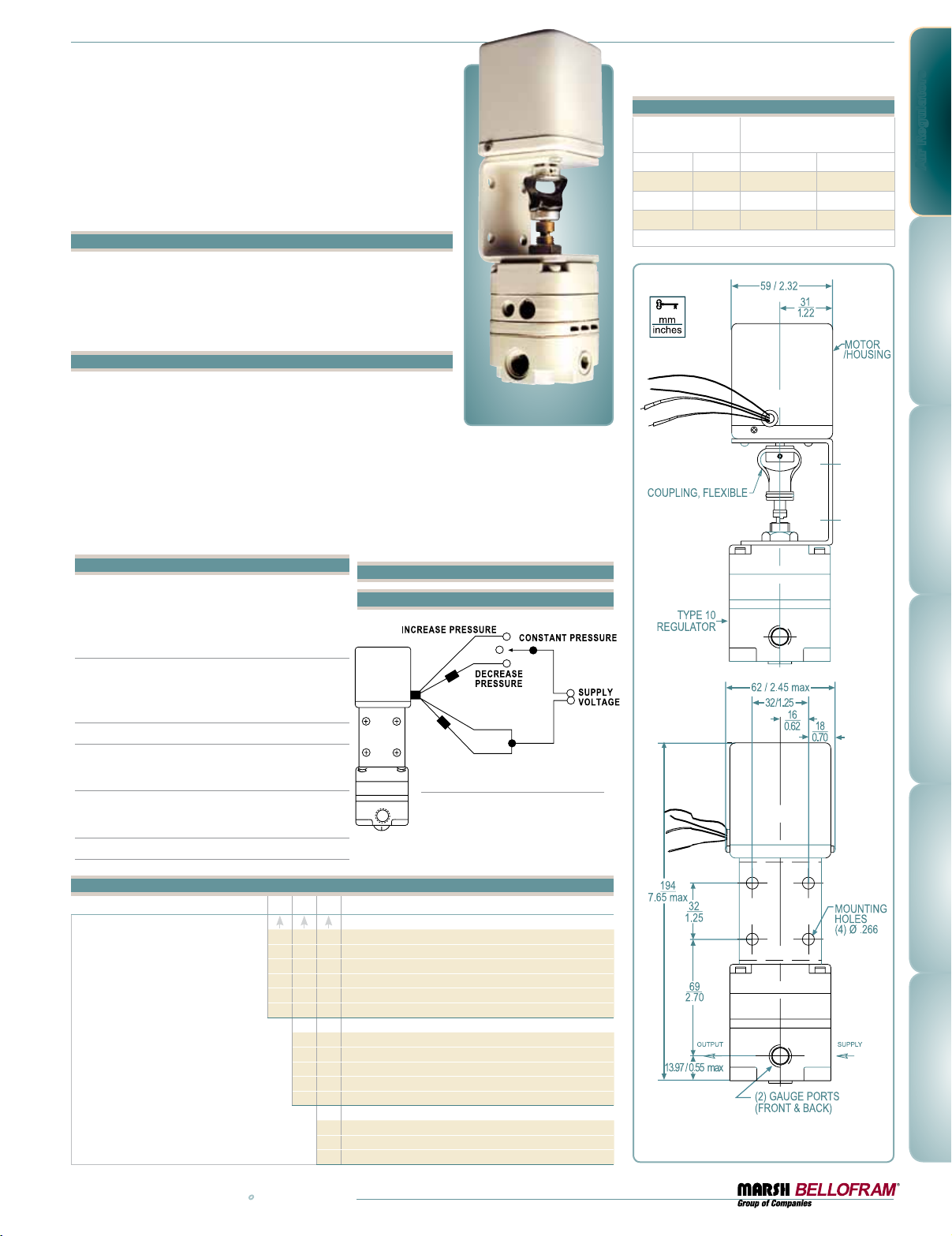
Type 10 Motorized
Pressure Regulators
Bellofram’s high precision Type 10 pressure regulator – a servo
balanced system in which the main valve is operated by a pilot
valve – is also available in a motorized configuration. This combination is particularly attractive because it offers low power requirements (2 rpm/4 watts; 6 rpm/6 watts) with extremely high accuracy.
Applications
The motorized Type 10 pressure regulator can be used for any
application where electric control of a pneumatic system is desired.
It is often used for remote pressure control and for ventilation systems. It can also be easily integrated into open or closed loop process
control systems and may be used with programmable controllers.
Features
•Mountable at any angle
•In the event of power failure, the pneumatic output remains
constant at last setting
•Low electrical power requirements
•Adjustable mechanical stop limits maximum output pressure
•No electrical power is required when operating at constant output pressure
•No pre-regulation of supply pressure required
•Built-in overload slip clutch prevents damage to gear train at end of travel,
eliminating the need for limit switches in most applications.
Construction
The regulator and motor are mounted to a bracket and
connected to each other through a flexible coupling. The
assembly can be mounted through holes in the bracket.
Motor Specifications
Reversible, synchronous motor with gear drive
and slip clutch.
Operating Voltage 110VAC, 24VAC, 24VDC or 220VAC.
Frequency
60 Hz, Except 220 VAC model is 50 Hz.
Power Consumption (maximum)
2 rpm/4 watts, 6 rpm/6 watts.
Speeds Available 2 and 6 rpm.
Torque Approx. 8 in. oz.
Typical Installation
Control Circuit Diagram
Note
To increase output pressure,
apply voltage to unmarked leads.
To decrease output pressure,
apply voltage to marked leads.
Regulator-Motor Specifications
Pressure Range
Approximate Time to Cover
Full Range (seconds)
BAR psig 2 rpm 6 rpm
0.1–1.7 2-25 75 25
0.1–4.1 2-60 90 30
0.1–8.3 2-120 150 50
*±10% manufacturing tolerance
Air Regulators
Motorized Type 10 Ordering Information
960 - 180 -
Motor Specifications
1
2
3
4
5
6
www.marshbellofram.com • 800.727.5646
2 RPM 110 VA C 4 WATTS 60 Hz
6 RPM 110 VA C 6 WATTS 60 Hz
6 RPM 220 VAC 6 WAT TS 50 Hz
2 RPM 24 VAC 4 W AT TS 60 Hz
6 RPM 24 VAC 6 W AT TS 60 Hz
6 RPM 24 VDC
Pressure Range
2-25 psig / 0.1–1.7 BAR
1
2-60 psig / 0.1–4.1 BAR
2
2-120 psig / 0.1–8.3 BAR
3
L. R. Model, 0.5-25 psig / 0.03–1.7 BAR
4
H.R. Model, 2-120 PSI / 0.1–8.3 BAR
5
Port Size
1/8 NPT
1
1/4 NPT
2
3/8 NPT
3
Drawings and dimensions
are for reference only.
5
Page 6
Air Regulators
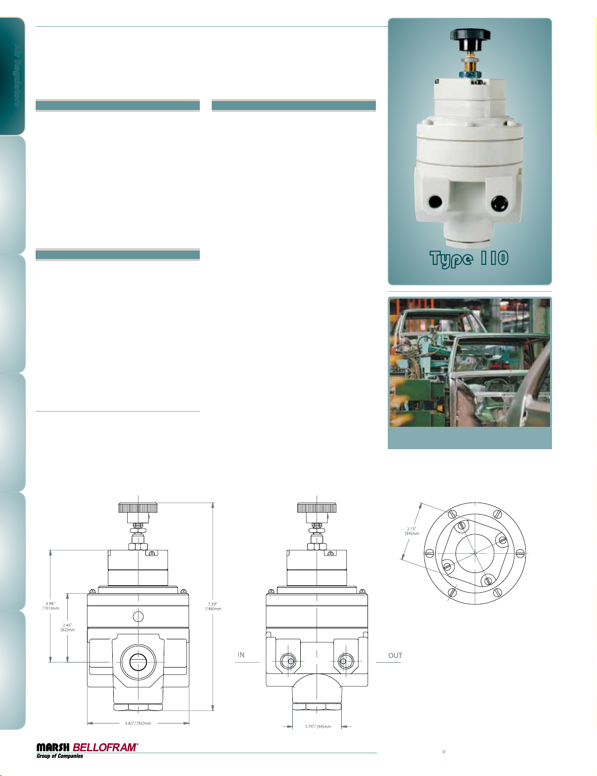
Type 110
Pressure Regulator Series
Features
•Highly Accurate Pressure Regulation
•Large Port Sizes Available:
3/8, 1/2, 3/4 and 1 NPT
(BSPP and BSPT also Available)
•Adjustment Stem Locking Capability
•High Forward Flow Capacity – 150+ SCFM
•High Exhaust Capacity
•Balanced Supply Valve
•Low Sensitivity to Supply Pressure Variations
•Low Sensitivity to Flow Variations
Applications
The Type 110 was developed specifically for
use with Air Balancing Systems or Zero-Gravity
Arms. Such systems require very small forward
to reverse flow offsets for smooth operation.
The precision regulators that can achieve the
sensitivity requirements do not typically possess the forward or exhaust capacity to handle
large balancing arms or cylinders. The Type
110 does not have this limitation. It is ideal for
use in any application where precise regulation
of pressure is required along with high flow or
high exhaust capacity.
Other typical applications
•Valve Operators
•Air Hoists
•Web Tensioning
•Roll Loading
•Large Cylinder Loading
•Air Brakes
•Force Balance Hoists
•Gate Actuators
Description
The Type 110 combines the proven technology
of the Marsh Bellofram Type 10 regulator with
the large pneumatic booster of the Type 79
Relay. The result is a precise, crisply responding
regulator that can achieve very large forward
and exhaust flows. Forward to reverse flow
offset is minimized by the capsule operated,
servo-control system located in the upper
portion of the regulator. This servo-control
system supplies a pilot pressure to the large
integral pneumatic booster. The large supply
and exhaust orifices of the integral booster
enable this regulator to produce very high
forward and exhaust flow rates. Few regulators
can offer this combination of sensitivity and
large flow capacity.
As with all of the Type 10 regulators, the
stainless steel measuring capsule is the “heart”
of the Type 110 Pressure Regulator. Originally
developed for sensitive aircraft altimeters, this
precision-sensing element provides the energy
to activate the servo-control mechanism.
It provides greater regulation and accuracy
while eliminating the problems usually
encountered with range springs and conventional diaphragms. Because of the balanced supply
valve in the integral pneumatic booster, the
Type 110 can work with higher supply pressures
(250 PSIG) than many other regulators.
Type 110
Pressure Regulator Series
6
800.727.5646 • www.marshbellofram.com
Page 7
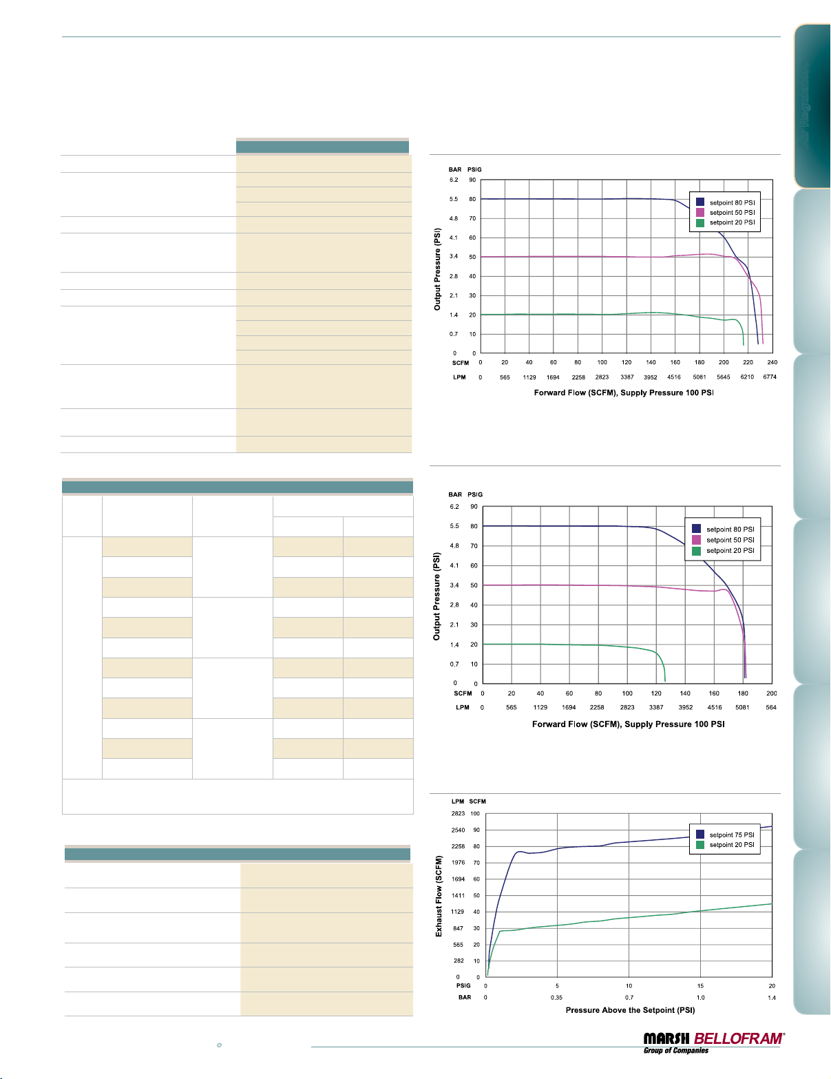
Type 110
Maximum Supply Pressure
Output Pressure Ranges
Port Sizes
Effect of Supply Pressure
Variation on Outlet Pressure
Sensitivity
Air Consumption
Forward Flow Capacity
(100 psig/ 6.9 BAR supply,
20 psig / 1.4 BAR set point)
0.01 psig / 0.6 mBAR change in output for a
250 PSIG / 17.2 BAR
2-25 PSIG / 0.14-1.7 BAR
2-50 PSIG / 0.14-3.5 BAR
2-110 PSIG / 0.14-7.6 BAR
3/8, 1/2, 3/4, 1 NPT, BSPT or BSPP
25 psig/1.7 BAR change in supply pressure
1/4" / 6.4 mm of water column
14 scfh / 6.6 slpm @ max output pressure
3/8 NPT - 110 SCFM+ / 3105 SLPM
1/2 NPT - 110 SCFM+ / 3105 SLPM
3/4 NPT - 200 SCFM+ / 5645 SLPM
1 NPT - 200 SCFM+ / 5645 SLPM
Exhaust Capacity
(based on raising output 5 psig / .34
BAR above 20 psig / 1.4 BAR set point)
Temperature Range
Weight
30 scfm / 847 slpm
-20˚ to +160˚F
-29˚ to +71˚C
5.4 lbs / 2.45 Kg
Type 110 Ordering Information
Part Number Port Size (NPT)
960-510-000
960-511-000 0.1-3.5 2-50
3/8
Pressure Ranges
BAR psig
0.1-1.7 2-25
960-512-000 0.1-7.6 2-110
T 110
960-513-000
960-514-000 0.1-3.5 2-50
1/2
960-515-000 0.1-7.6 2-110
960-516-000
960-517-000 0.1-3.5 2-50
3/4
0.1-1.7 2-25
0.1-1.7 2-25
960-518-000 0.1-7.6 2-110
960-519-000
960-520-000 0.1-3.5 2-50
1
960-521-000 0.1-7.6 2-110
0.1-1.7 2-25
For BSPT or BSPP pipe threads, add BSPT or BSPP to the end of the
part number. For mounting bracket , order P/N 607-293-000
Type 110: Forward Flow Curve, 3/4 and 1 NPT
Type 110: Forward Flow Curve, 3/8 and 1/2 NPT
@ 100 PSIG Supply Pressure
Type 110: Exhaust Curve
Air Regulators
Type 110 Materials of Construction
Body, bonnet and housing
Capsule and adjustable screw
Spacer
Diaphragm
Trim
Nitrile Elastomer and Polyester Fabric
Stainless Steel, Brass, Plated Steel, Acetal
Knob
www.marshbellofram.com • 800.727.5646
Die Cast Zinc Alloy
Stainless Steel
Aluminum
Phenolic Plastic
7
Page 8
Air Regulators
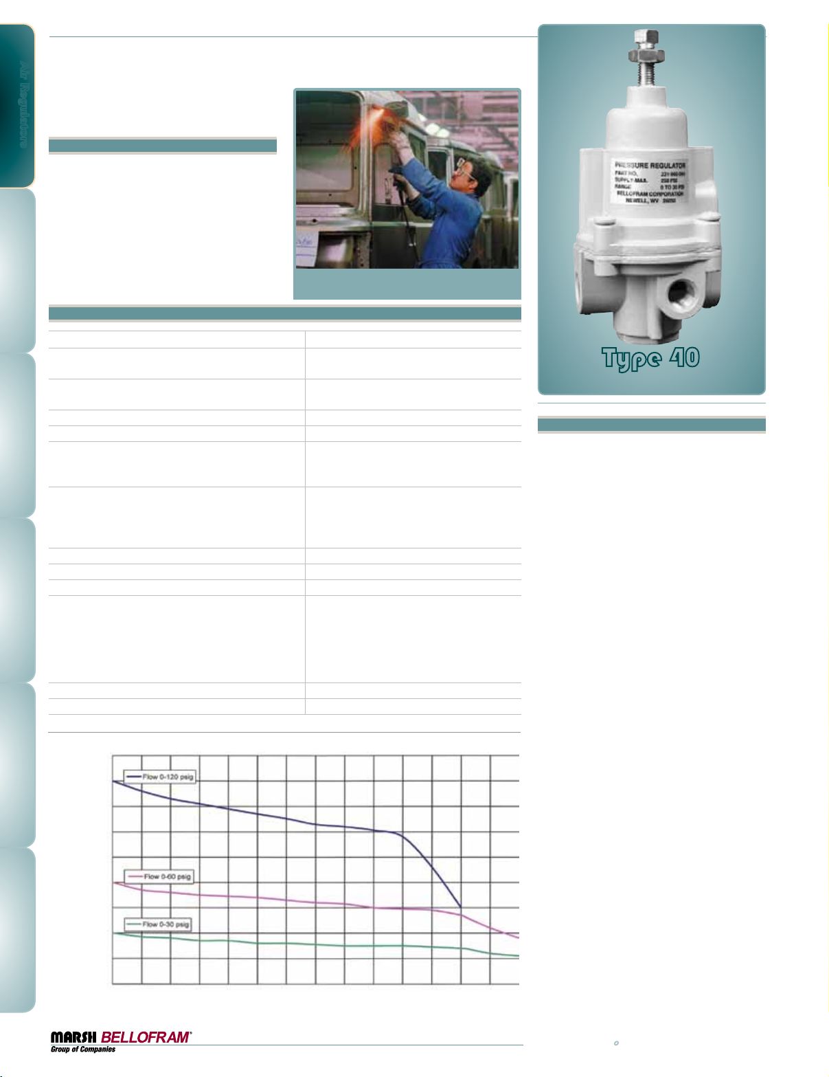
Type 40
Pressure Regulator Series
Features
•Superior regulation characteristics
•Rugged, corrosion resistant construction
•Low cost
•Excellent stability and repeatability
•Self-relieving
•Low droop at high flow
•Several mounting options
Type 40 Specifications
Sensitivity 1" Water Column (2.5 cm)
Flow Capacity @ 100 psig (6.9 BAR) Supply
and 20 psig (1.4 BAR) outlet
Effect of Supply Pressure Variation
(25 psig/1.7 BAR) on Outlet Pressure
Exhaust Capacity 5 psig (0.35 BAR) above 20 PSIG set point 0.1–0.45 SCFM Typical 2.8 - 12.7 LPM
Max Supply Pressure 250 PSIG (17.2 BAR)
Effect of Changes in Flow on Regulated Pressure
(100 psig / 6.9 BAR Supply)
Output Pressure Ranges
Temperature Range 0-160˚F (-18 to 71˚C)
Total Air Consumption @ Maximum Output 6 SCFH (2.8 LPM)
Port Size 1/4 NPT, BSPT
Materials of Construction
Tamper Resistant Cover Optional
Mounting Options Pipe, Panel or Bracket
Type 40: Regulated Pressure VS. Flow
PSIG BAR
90 6.2
80 5.5
70 4.8
60 4.1
50 3.4
Regulated PRessuRe
40 2.8
30 2.1
20 1. 4
10 0.7
0 0
SCFM 0 2 4 6 8 10 12 14 16 18 20 22 24 26 28
LPM 0 57 113 170 227 283 340 397 453 510 566 623 680 736 793
8
20 SCFM (566 LPM)
Less than 0.2 psig (0.01 BAR)
2 PSIG over flow of 10 SCFM / 283 LPM
(0-30 PSIG / 0-2.1 BAR range 1/4 NPT,
20 PSIG / 1.4 BAR set point)
0-10 PSIG (0-0.7 BAR)
0-35 PSIG (0-2.4 BAR)
0-60 PSIG (0-4.1 BAR)
0-120 PSIG (0-8.3 BAR)
Body: Die cast aluminum with vinyl paint
Adjusting Screw: Plated steel
Trim: Plated steel, brass, acetal resin
Diaphragm: Buna-N elastomer and polyester
fabric Knob: Phenolic Plastic (option)
Spring: Music wire
FoRwaRd Flow
Type 40
Pressure Regulator Series
Description
Marsh Bellofram’s General Purpose Type 40
Pressure Regulator is a reliable precision unit
designed for instrumentation and general
purpose use.
Test data for the Type 40 regulator shows
excellent performance characteristics compared
with those of similar units presently on the market. The Type 40 regulator is generally superior
in regulated pressure vs. flow, forward-to-reverse flow offset, supply pressure sensitivity,
repeatability and stability.
Ruggedly designed and constructed, the Type
40 has housings of diecast aluminum. Every
regulator is finished with vinyl paint (which
resists scratching, weathering and other
physical abuse) and is pressure and leak tested
prior to shipment from the factory. Careful
design and quality materials throughout assure long, trouble-free operation in the most
difficult industrial environments. A rubberized,
soft-seat valve stem provides positive shut-off
and “forgives” dirt or other foreign matter. An
aspirator maintains downstream pressure and
compensates for droop when high flow occurs.
The gauge port is convenient for gauge installation and can also be used as an additional full
flow outlet.
The Type 40 regulator has a 60-mesh 304 stainless steel screen to block foreign particles from
entering the output stream. The design of these
regulators is especially well suited to pilot-operated controllers and instruments, as well as
applications such as air chucks, air spray guns,
air cylinders and actuators, and a wide range of
industrial pneumatic systems and equipment.
800.727.5646 • www.marshbellofram.com
Page 9
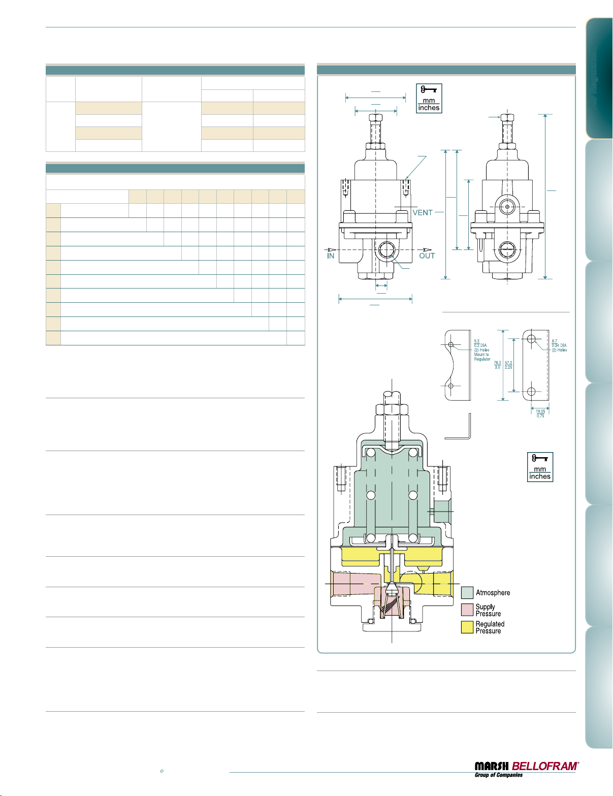
Type 40 Ordering Information
Set Point Range
BAR psig
0-0.7 0-10
T40
Part Number Port Size (NPT)
960-063-000
960-064-000 0-2.4 0-35
1/4
960-065-000 0-4.1 0-60
960-066-000 0-8.3 0-120
Type 40 Option Ordering Matrix
Replace last three digits of part number with digits from table below.
Option
Fluorocarbon Pintle 001 021 031 051 061 071 081 091 101 111
1
Non-Relieving 002 032 052 072 082 092 112
2
Knob 003 053 063 073 083 103 113
3
Epoxy Finish 005 065 075 085 095 105 115
5
Tapped Vent 006 076 086 096 106 116
6
Mounting Bracket 007 087 09 7 107 117
7
Pressure Gauge 008 098 108 118
8
Tamper-Resistant Cover 009 109 119
9
Soft Relief Seat 010 110
10
Fluorocarbon Diaphragm 011
11
1235678910 11
To order BSPT threads (including the gauge port)
add “BSPT” to end of part number.
Type 40 Dimensional Drawing
52.3
2.06
36.6
1.44
10–24 UNC–2B
X 0.37 (9.4 mm) DEEP
(2 PLACES)
82.5
3.25
106.7
60.2
4.2
2.37
!/4” – 18 NPT
Gauge Port
0.38
9.62
63.5
2.5
Optional Mounting Bracket
607-000-057
5/16" SQ.
143
5.63
@ 20 psig
(1.4 BAR)
Adjustment
Air Regulators
Fluorocarbon Pintle
A special elastomeric pintle used where elements in the supply air, such
as flame retardant synthetic lubricants, are particularly destructive to
ordinary pintle material.
Non Relieving
Used in applications where it is desirable to relieve pressure downstream
of the regulator, for some constant flow applications, and where the gas
flowing through the regulator must not escape at the regulator. Non-relieving regulators should not be used for low or no flow applications.
Corrosive Resistant Epoxy Finish
An epoxy paint applied to the body and bonnet of the regulator exterior
surfaces to provide increased corrosion resistance.
Mounting Bracket
Steel (dichromate finish) bracket for side mounting. P/N: 607-000-057
Knob
Option to replace the square head pressure adjusting screw.
Tapped Vent
Allows installation of plumbing to capture exhaust air.
Pressure Gauge
Dual scale 2 in. (50.8 mm) gauges. Ranges include 0-30 psig (0-200
kPa), 0-60 psig (0-400 kPa), 0-100 psig (0-700 kPa) and 0-160 psig
(0-1100 kPa). When specified with regulator, the correct range will be
supplied. For NPT versions only.
Tamper Resistant Cover
An aluminum tubular cover placed over a slotted head adjusting screw and
screwed onto the bonnet of the regulator with a wrench. Prevents ordinary
hand adjustments.
Drawings and
dimensions are
for reference only.
Soft Relief Seat
Used in applications where it is desirable to reduce the standard bleed
rate from 6 SCFH [0.17 m3hr] to less than 0.1 SCFH [0.003 m3hr].
Fluorocarbon Diaphragm
Diaphragm as well as all seals are made of fluorocarbon elastomer to prevent deterioration from elements in the air supply, such as flame retardant
synthetic lubricants normally destructive to standard Nitrile material.
www.marshbellofram.com • 800.727.5646
9
Page 10
Air Regulators
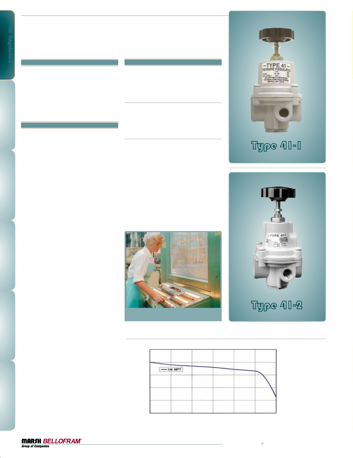
Type 41-1 & Type 41-2
Pressure Regulator Series
Features
•Superior regulation characteristics
•Rugged, corrosion-resistant construction
•Excellent stability and repeatability
•Self-relieving of excess down stream pressure
•Low droop at high flow
•Mounting options available
Description
The Type 41 regulators are designed for applications requiring high flow capacity, low droop,
high accuracy, and fine adjustment sensitivity.
The use of Bellofram’s rolling diaphragm provides greater sensitivity and improved accuracy.
In addition, Type 41 regulators offer reduced
over-all size and several mounting options,
providing direct interchangeability with more
expensive competitors’ units.
Ruggedly designed and constructed, the Type
41 regulators have housings of precision-cast
aluminum. They are pressure tested, and
are chromate treated for internal corrosion
resistance. Every regulator is finished with vinyl
paint which resists scratching, weathering and
other physical abuse.
Careful design and quality materials throughout
assure long, trouble-free operation in the most
difficult industrial environments. A rubberized,
soft-seat valve stem provides stability and
“forgives” dirt and other foreign matter. An
aspirator maintains downstream pressure and
compensates for droop when high flow occurs.
The gauge port is convenient for gauge installation and can also be used as an additional full
flow outlet.
The design of these regulators is especially
well suited for panel applications due to ease of
mounting (only one panel hole required), small
size, adjustment sensitivity (32 threads per inch
on the adjusting screw), and knob.
Models
The Type 41 comes in two versions, Type 41-1
and Type 41-2. These two regulators offer the
same performance in two slightly different
packages.
Type 41-1
This unit comes standard with 1⁄4 NPT ports
and a knob, and can be panel mounted using
either the center nut or the threaded shoulder
holes, spaced 1.5 in. (38.1 mm) center-to-center.
Type 41-2
This unit comes standard with 1⁄4 NPT ports,
a knob and a bonnet vent port which can be
tapped for a 1⁄4 NPT fitting if desired. It can
be panel mounted using either the center nut
or the threaded shoulder holes, spaced 1.25 in.
(32.7 mm) center-to-center.
Type 41: Regulated Pressure VS. Flow
PSIG BAR
25 1. 7
Type 41-1
Pressure Regulator Series
Type 41-2
Pressure Regulator Series
10
20 1. 4
15 1. 0
10 0.7
Regulated PRessuRe
5 0.3
0 0
SCFM 0 5 10 15 20 25 30
LPM 0 142 283 425 566 708 850
FoRwaRd Flow
800.727.5646 • www.marshbellofram.com
Page 11
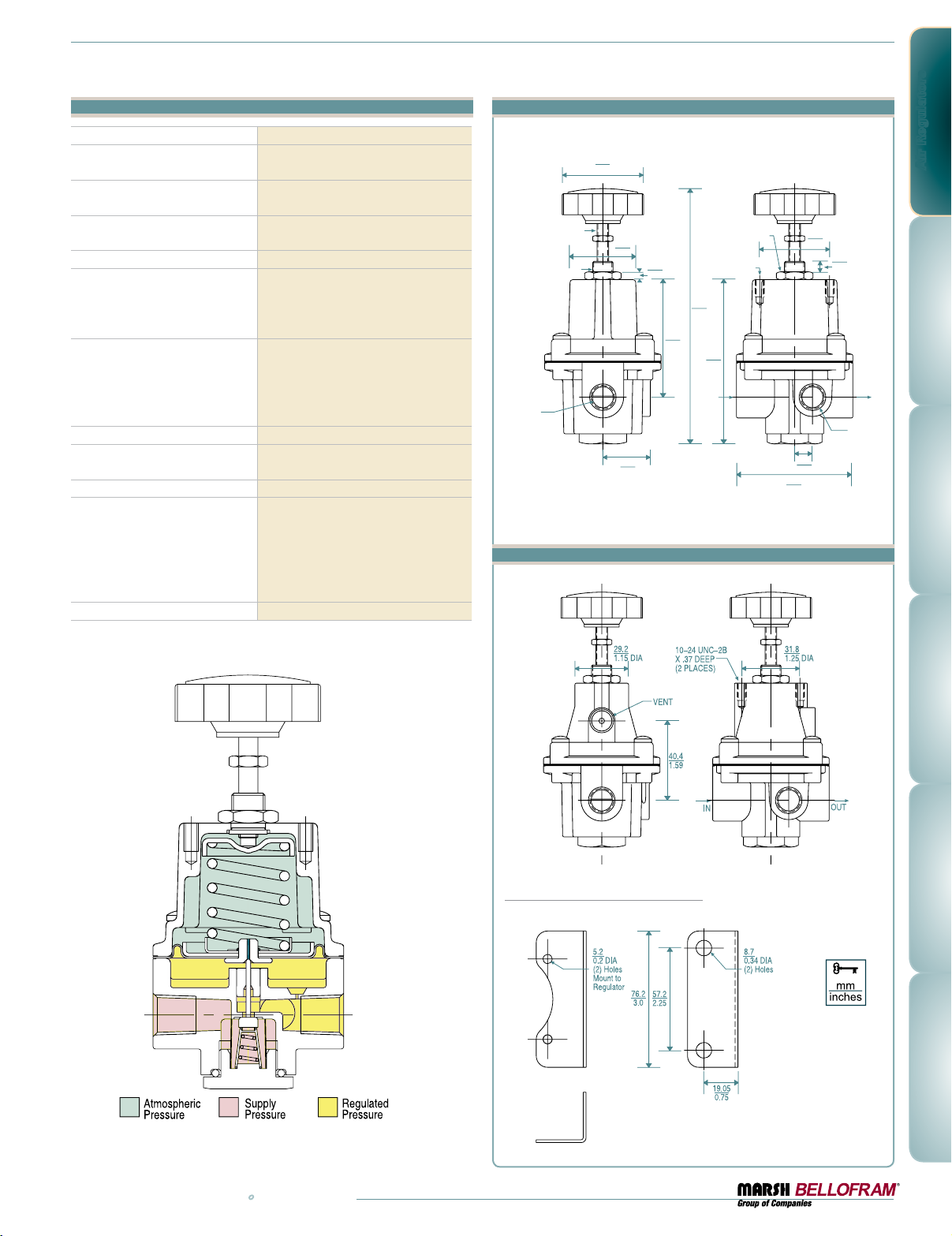
44.5
1.75 DIA
35.6
1.40
DIA
1/4–32 UNEF–3A
7/16–20 UNF–2A
1/4–18 NPT
IN & OUT PORTS
25.4
1.0
63.5
2.5
146.1
5.75
88.6
3.49
11/16 HEX PANEL
MOUNTING NUT
10–24 UNC–2B X .37
DEEP (2 PLACES)
4.8
0.19
10.2
0.4
38.1
1.5
1/4–18 NPT
GAUGE PORTS
9.4
0.37
63.5
2.5
IN
OUT
T41 Regulator Specifications
Sensitivity 1" Water Column (2.5 cm)
Flow Capacity @ 100 psig (6.9 BAR)
Supply and 20 psig (1.4 BAR) outlet
Effect of Supply Pressure Variation
(25 psig/1.7 BAR) on Outlet Pressure
Exhaust Capacity 5 psig (0.35 BAR)
above 20 psig set point
Max Supply Pressure 250 PSIG (17.2 BAR)
Effect of Changes in Flow on
Regulated Pressure
(100 psig / 6.9 BAR Supply)
Output Pressure Ranges
Temperature Range 0-160˚F (-18 to 71˚C)
Total Air Consumption
@ Maximum Output
Port Size 1/4 NPT, BSPT
Materials of Construction
Mounting Options Pipe, Panel or Bracket
25 SCFM (700 LPM)
±0.35 PSIG
(24 mBAR)
0.1–0.45 SCFM Typical 2.8 - 12.7 LPM
1 psig (0.07 BAR) over flow
of 10 SCFM (0-30 psig / 0-2.1 BAR
range, 1/4 NPT, 20 psig / 1.4 BAR set
point)
0-2 PSIG (0-0.14 BAR)
0-10 PSIG (0-0.69 BAR)
0-30 PSIG (0-2.1 BAR)
0-60 PSIG (0-4.1 BAR)
0-100 PSIG (0-6.9 BAR)
6 SCFH (2.8 LPM)
Body: Die cast aluminum with vinyl paint
Adjusting Screw: Plated steel
Trim: Plated steel, brass, acetal resin
Diaphragm: Buna-N polyester fabric
Knob: Phenolic Plastic
Spring: Music wire
Type 41-1 Dimensional Drawing
Air Regulators
Type 41-2 Dimensional Drawing
www.marshbellofram.com • 800.727.5646
Optional Mounting Bracket
607-000-057
11
Page 12
Air Regulators
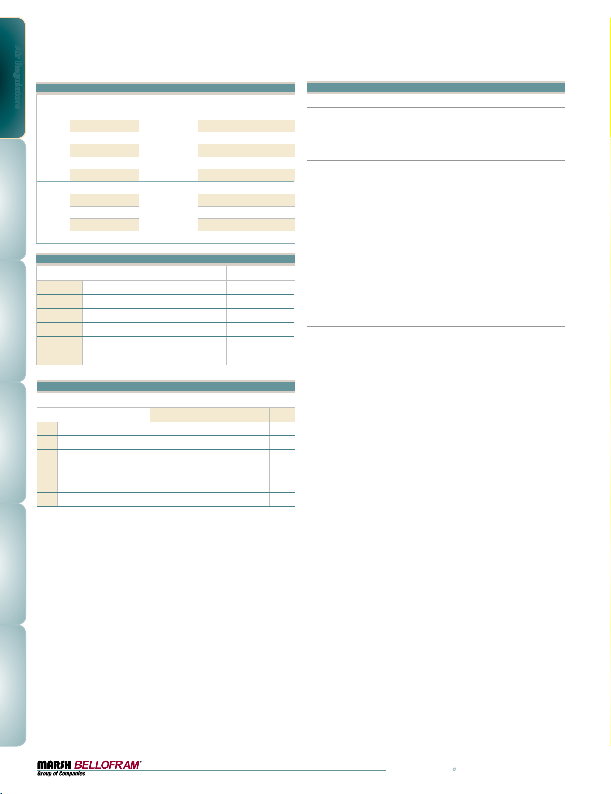
Type 41 Ordering Information
Part Number Port Size (NPT)
960-113-000
960-114-000 0-0.69 0-10
T41-1
960-170-000 0-2.1 0-30
1/4
960-171-000 0-4.1 0-60
960-172-000 0-6.9 0-100
960-115-000
T41-2
960-116-000 0-0.69 0-10
960-181-000 0-2.1 0-30
1/4
960-182-000 0-4.1 0-60
960-183-000 0-6.9 0-100
Type 41 Options
•=optionisavailable
Fluorocarbon Pintle • •
1
Non-Relieving • •
2
Epoxy Finish • •
5
Tapped Vent n/a •
6
Mounting Bracket • •
7
Pressure Gauge • •
8
Set Point Range
BAR psig
0-0.14 0-2
0-0.14 0-2
T41-1 T41-2
Type 41 Regulator Options and Accessories
Fluorocarbon Pintle
A special elastomeric pintle used where elements in the supply air, such
as flame retardant synthetic lubricants, are particularly destructive to
ordinary pintle material.
Non-Relieving
Used in applications where it is desirable to relieve pressure downstream
of the regulator, for some constant flow applications, and where the gas
flowing through the regulator must not escape at the regulator. Non-relieving regulators should not be used for low or no flow applications.
Corrosive Resistant Epoxy Finish
An epoxy paint applied to the outside surface of the regulator to provide
increased resistance to corrosive environments.
Tapped Vent (41-2 only)
Allows installation of plumbing to capture exhaust air.
Mounting Bracket
Steel (dichromate finish) bracket for side mounting. P/N: 607-000-057
Pressure Gauge
Dual scale 2 in. (50.8 mm) gauges. Ranges include 0-30 psig (0-200
kPa), 0-60 psig (0-400 kPa), 0-100 psig (0-700 kPa) and 0-160 psig
(0-1100 kPa). When specified with regulator, the correct range will be
supplied.
Type 41 Option Ordering Matrix
Replace last three digits of part number with digits from table below.
Option
Fluorocarbon Pintle 001 021 051 061 071 081
1
Non-Relieving 002 052 062 072 082
2
Epoxy Coating 005 065 075 085
5
Tapped Vent 006 076 086
6
Mounting Bracket 007 087
7
Pressure Gauge 008
8
125678
12
800.727.5646 • www.marshbellofram.com
Page 13
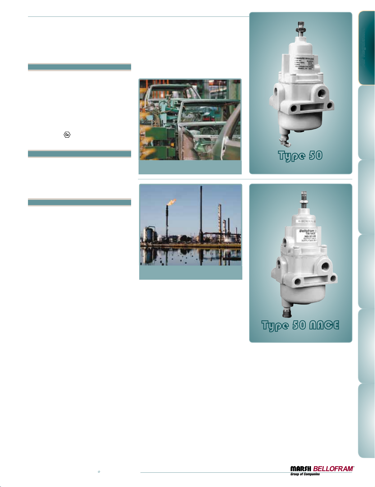
Type 50 & Type 50 NACE
Filter Regulator Series
Features
•Superior regulation characteristics
•Rugged, corrosion-resistant construction
•Excellent stability and repeatability
•Self-relieving
•Integral, 40 micron, self cleaning filter
•Low droop at high flow
•Several mounting options
•Meets ATEX
(Non-electrical certification)
Applications
The design of these regulators is well suited
to pilot-operated controllers, and instruments,
applications such as air chucks, air spray guns,
air cylinders and actuators, and a wide range of
industrial pneumatic systems and equipment.
Description
Marsh Bellofram’s General Purpose Type
50 and Type 50 NACE Filter Regulators
are reliable precision units designed for
instrumentation and general purpose use in
both standard environments (Type 50), and
corrosive environments (Type 50 NACE). The
Type 50 NACE complies with NACE material
requirement #MR-01-75 for sulfide stress
cracking resistant metallic material for oil field
equipment.
Test data for these regulators show excellent
performance characteristics compared with
those of similar units
presently on the market.
These Marsh Bellofram
regulators are generally superior in regulated pressure vs. flow,
forward-to-reverse flow
offset, supply pressure
sensitivity, repeatability
and stability.
Ruggedly designed and
constructed, the regulators have housings of diecast aluminum. The
Type 50 Regulator is finished with vinyl paint
(which resists scratching, weathering and
other physical abuse), while the Type 50 NACE
is finished with epoxy paint for added protection. Both models are pressure and leak tested
prior to shipment from the factory.
II 2 G Dc T 6
The Type 50 NACE is
available for use in
corrosive environments.
This complies with
NACE material requirement
#MR0175 for sulfide stress
cracking resistant metallic
material for oil field
equipment.
Careful design and
quality materials
throughout assure
long, trouble-free
operation in the most
difficult industrial
environments. A rubberized, soft-seat
valve stem provides
positive shut-off and
“forgives” dirt or
other foreign matter.
An aspirator main-
tains downstream
pressure and compensates for droop when high
flow occurs. The gauge port is convenient for
gauge installation and can also be used as an
additional full flow outlet. The Type 50 regulators include a unique self-cleaning 40 micron
nylon mesh filter (316 stainless steel in the
Type 50 NACE) that can be easily removed.
Air Regulators
Type 50
Pressure Regulator Series
Type 50 NACE
Pressure Regulator Series
Contact Us About
IP65 Compatible
T50 FR
www.marshbellofram.com • 800.727.5646
13
Page 14
Air Regulators
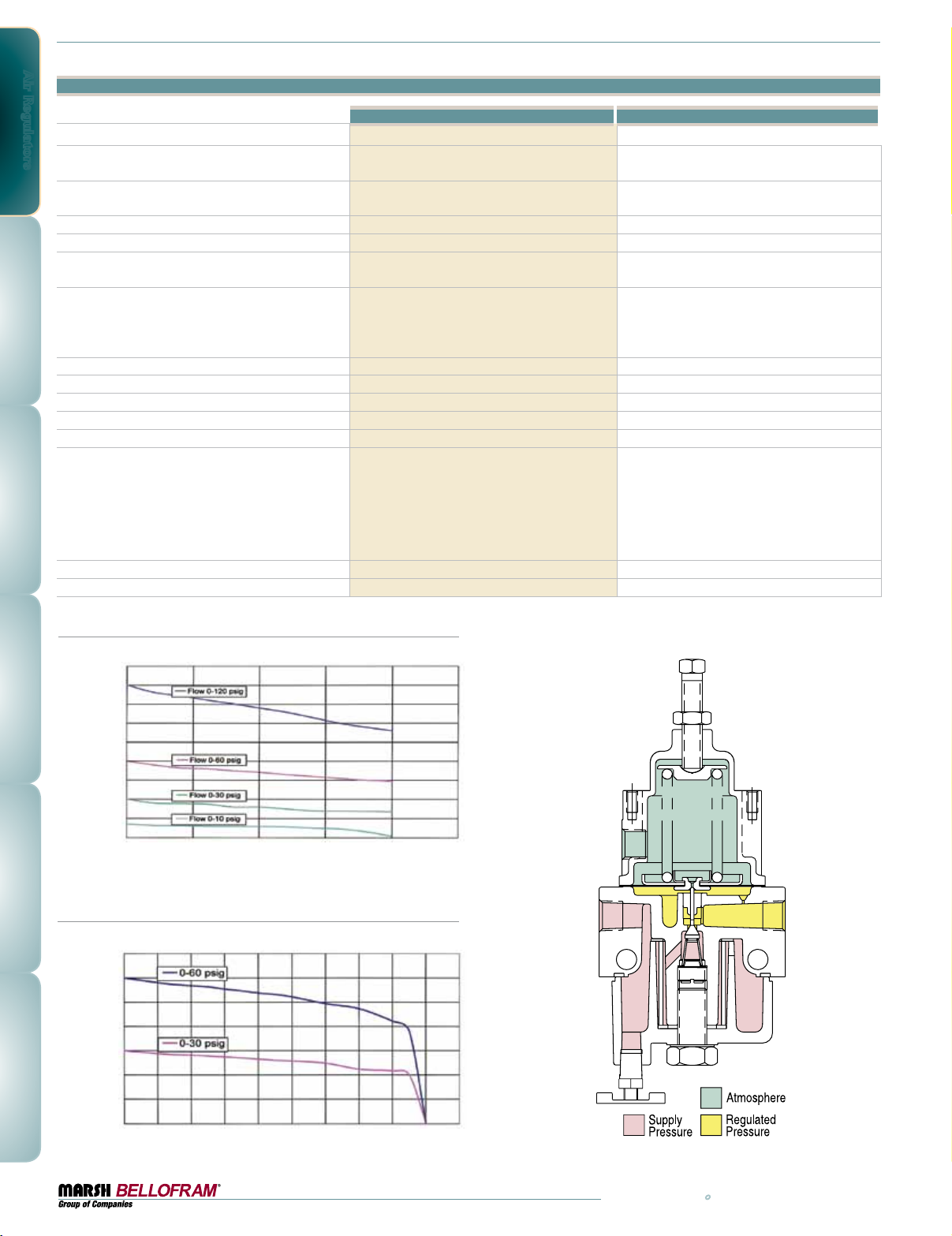
Type 50 and 50 NACE Specifications
Type 50 Type 50 NACE
Sensitivity 1" Water Column (2.5 cm) 1" Water Column (2.5 cm)
Flow Capacity @ 100 PSIG (6.9 BAR) Supply
and 20 PSIG (1.4 BAR) outlet
Effect of Supply Pressure Variation
(25 PSIG/1.7 BAR) on Outlet Pressure
Exhaust Capacity 5 psig (0.35 BAR) above 20 psig set point 0.1–0.45 SCFM Typical (2.8 - 12.7 LPM) 0.1–0.45 SCFM Typical (2.8 - 12.7 LPM)
Maximum Supply Pressure 250 PSIG (17.2 BAR) 250 PSIG (17.2 BAR)
Effect of Changes in Flow on Regulated Pressure
(100 PSIG / 6.9 BAR Supply)
Output Pressure Ranges
Temperature Range 0-160˚F (-18 to 71˚C) -20 to 180˚F (-29 to 82˚C)
Total Air Consumption @ Maximum Output 6 SCFH (2.8 LPM) 6 SCFH (2.8 LPM)
Port Size 1/4 NPT, BSPT 1/4 NPT, BSPT
Size 3.19" X 3.19" X 7.25" (81 X 81 X 184 mm) 3.19" X 3.19" X 7.25" (81 X 81 X 184 mm)
Weight 1.81 lb. (0.8 kg) 1.81 lb. (0.8 kg)
Materials of Construction
Tamper Resistant Cover Yes Yes
Mounting Options Pipe, Panel, Bracket or Thru Body Holes Pipe, Panel, Bracket or Thru Body Holes
20 SCFM (566 LPM) 18 SCFM (510 LPM)
< 0.2 psig (0.01 BAR) < 0.2 PSIG (0.01 BAR)
4 PSIG / 0.3 BAR over flow of 10 SCFM / 283 LPM
(1/4 NPT, 20 PSIG / 1.4 BAR set point)
0-10 PSIG (0-0.7 BAR)
0-35 PSIG (0-2.4 BAR)
0-60 PSIG (0-4.1 BAR)
0-120 PSIG (0-8.3 BAR)
Body: Die cast aluminum with vinyl paint
Adjusting Screw: Plated steel
Trim: Plated Steel, Brass, Acetal Resin
Diaphragm: Buna-N Elastomer and Polyester Fabric
Knob: Phenolic Plastic (option)
Spring: Music wire
5 PSIG / 0.3 BAR over flow of 10 SCFM / 283 LPM
(1/4 NPT, 20 psig / 1.4 BAR set point)
0-30 PSIG (0-2.1 BAR)
0-60 PSIG (0-4.1 BAR)
0-120 PSIG (0-8.3 BAR)
Body: Die cast aluminum with epoxy paint
Adjusting Screw: Stainless steel
Trim: Stainless steel, Neoprene, EPDM
Diaphragm: Neoprene, Polyester Fabric
Spring: Inconel
Type 50: Regulated Pressure VS. Flow
PSIG BAR
90 6.2
80 5.5
70 4.8
60 4.1
50 3.4
40 2.8
30 2.1
20 1. 4
Regulated PRessuRe
10 0.7
0 0
SCFM 0 5 10 15 20 25
LPM 0 142 283 425 566 708
FoRwaRd Flow
Type 50: Regulated Pressure VS. Flow
PSIG BAR
70 4.8
60 4.1
50 3.4
40 2.8
30 2.1
20 1. 4
10 0.7
Regulated PRessuRe
0 0
sCFM 0 2 4 6 8 10 12 14 16 18 20
l PM 0 57 113 17 0 227 283 340 397 453 510 566
F
oRwaRd Flow
14
800.727.5646 • www.marshbellofram.com
Page 15
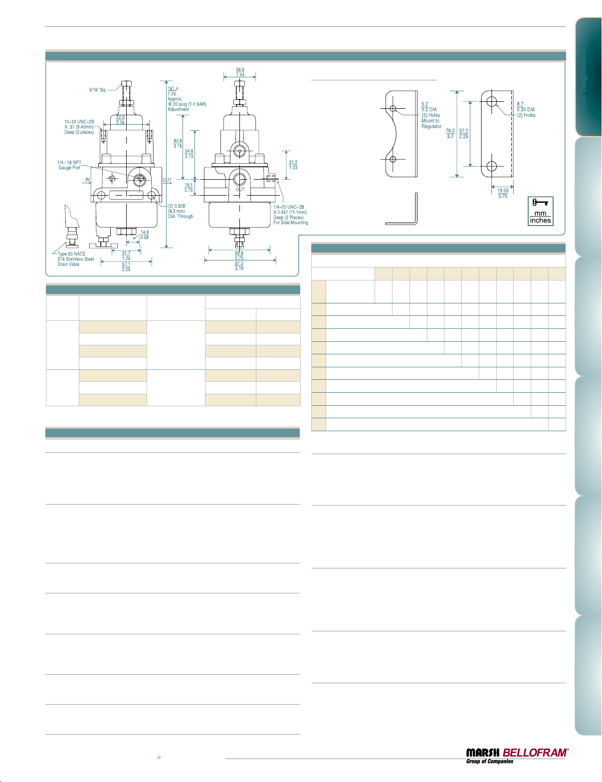
Type 50 Dimensional Drawing
Type 50 Ordering Information
Set Point Range
BAR PSIG
0-0.7 0-10
0-2.1 0-30
T50
T50
NACE
Part Number Port Size (NPT)
960-062-000
960-067-000 0-2.4 0-35
960-068-000 0-4.1 0-60
960-069-000 0-8.3 0-120
960-300-000
960-301-000 0-4.1 0-60
960-302-000 0-8.3 0-120
1/4
1/4
Type 50 Regulator Options and Accessories
Fluorocarbon Pintle
A special elastomeric pintle used where elements in the supply air, such as
flame retardant synthetic lubricants, are particularly destructive to ordinary
pintle material.
Non Relieving
Used in applications where it is desirable to relieve pressure downstream of
the regulator, for some constant flow applications, and where the gas flowing
through the regulator must not escape at the regulator. Non-relieving regulators should not be used for low or no flow applications.
Knob
Option to replace the square head pressure adjusting screw.
5 Micron Filter
Replaces the 40 micron filter supplied with the standard Type 50 for more
complete air filtration.
Corrosive Resistant Epoxy Finish
An epoxy paint applied to the body and dripwell of the regulator exterior surfaces to
provide increased corrosion resistance. (Standard with Type 50 NACE)
Tapped Vent
Allows installation of plumbing to capture exhaust air. (Standard with T-50 NACE)
Mounting Bracket: Type 50
Steel (dichromate finish) bracket for side mounting.
Type 50 NACE
Stainless Steel bracket for side mounting.
www.marshbellofram.com • 800.727.5646
Optional Mounting Bracket
607-000-057
Type 50 Option Ordering Matrix
Replace last three digits of part number with digits from table below.
Option
Fluorocarbon
1
Pintle
Non-Relieving 002 032 042 052 072 082 092 112
2
Knob 003 043 053 063 073 083 10 3 113
3
5 Micron Filter 004 054 064 074 084 094 104 11 4
4
Epoxy Finish 005 065 075 085 095 10 5 115
5
Tapped Vent 006 076 086 096 106 11 6
6
Mounting Bracket 007 0 87 097 107 117
7
Pressure Gauge 008 098 10 8 118
8
Tamper-Resistant Cover 009 109 119
9
Soft Relief Seat 010 110
10
Fluorocarbon Diaphragm 011
11
Pressure Gauge: Type 50
12345678910 11
001 0 21 031 0 41 0 51 061 071 0 81 0 91 101 111
Dual scale 2 in. (50.8 mm) gauges. Ranges include 0-30 PSIG (0-200 kPa),
0-60 PSIG (0-400 kPa), 0-100 PSIG (0-700 kPa) and 0-160 PSIG (0-1100
kPa). When specified with regulator, the correct range will be supplied.
Type 50 NACE
A dual scale, 0-60 PSIG (0-400 kPa) P/N 625-000-016, or 0-200 PSIG (0-1400
kPa) P/N 625-000-018, 2.47" diameter (63mm) stainless steel pressure gauge
is available and must be ordered separately. NOTE: Although the case is stainless steel, the internal components are not made of NACE qualified materials.
Tamper Resistant Cover
An aluminum tubular cover placed over a slotted head adjusting screw and
screwed onto the bonnet of the regulator with a wrench. Prevents ordinary
hand adjustments. Supplied with an o-ring that is designed to seal the
adjusting screw threads in capture bleed applications.
Soft Relief Seat
Used in applications where it is desirable to reduce the standard bleed rate
from 6 SCFH [0.17 m3hr] to less than 0.1 SCFH [0.003 m3hr].
(Not available with Type 50 NACE)
Fluorocarbon Diaphragm
Diaphragm as well as all seals are made of fluorocarbon elastomer to
prevent deterioration from elements in the air supply, such as flame retardant
synthetic lubricants normally destructive to standard Buna-N material.
To order BSPT add “BSPT” to end of part number.
Air Regulators
15
Page 16
Air Regulators
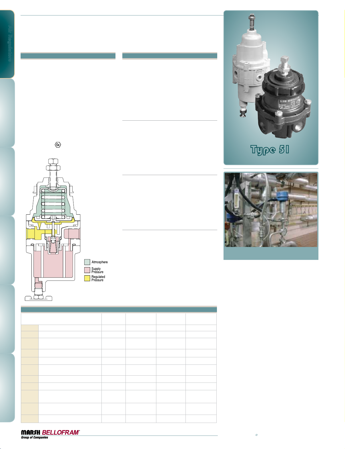
Type 51
Pressure Regulator Series
Features
•Excellent regulation, stability
and repeatability
•Corrosion-resistant construction (no brass
components, Type 51FR and Type 51AFR)
•NACE Constructed (Type 51FRCT Corrosive Tec)
•Low droop
•Small package size
•Panel, bracket or pipe mounting
•Fluorocarbon pintle seat
(Type 51FR, Type 51AFR and Type 51FRCT)
•Auto drain option (Type 51AFR)
•Meets ATEX
II 2 G Dc T 6
(Non-electrical certification)
Description
The Bellofram Type 51 Precision Air Regulator
series offers a high-performance regulator in
a compact, low cost package. It operates in
output pressure ranges up to 100 PSIG / 6.9
BAR (120 PSIG / 8.3 BAR in T-51FR Corrosive
Tec), with a maximum supply pressure of 250
psi (17.3 BAR).
Materials of Construction for
Standard Type 51 Series Regulators
Diecast aluminum for the body and dripwell;
glass-reinforced thermoplastic polyester for the
bonnet; acetal resin for the internals; BUNA-N
for the diaphragm, gaskets and O-ring, fluorocarbon for the pintle seat, and aluminum for the
drain valve (plated steel handle).
Materials of Construction for
Corrosive Tec Type 51FRCT
Aluminum alloy bonnet, body, and filter bowl,
316 stainless steel internals, Inconel alloy
range spring, nitrile diaphragm (fluorocarbon
optional), 316 stainless steel valve assembly,
and finished with an epoxy paint. All metallic
parts for this unit conform to NACE material
requirements #MR-01-75.
Materials of Construction for 51FRWT
Aluminum alloy bonnet, body, and filter bowl,
acetal resin, plated steel and aluminum internals. Nitrile diaphragm and finished with an
vinyl paint.
T51 FRCT
T51 R
Type 51
Pressure Regulator Series
Type 51 Options
1
2
3
4
5
6
7
8
9
10
11
16
From industry to industry, Marsh Bellofram’s Type 51 Series
of Regulators offer a low-cost, high performance option
for a wide range of applications.
•=optionisavailable
s=optionisstandard
Fluorocarbon Pintle • s s s
Non-Relieving •• • •
Knob
Sq. Head Adj. Screw
5 Micron Filter • • •
Epoxy Finish •• • s
Tapped Vent
Coalescing Filter
Mounting Bracket •• • •
Pressure Gauge •• • •
Tamper Resistant Cover
Panel Nut Mount ss s
Soft Relief Seat
Low Bleed •
Fluorocarbon Diaphragm •• • •
Type 51R Type 51FR Type 51AFR Type 51FRCT
•
s
•
s
•
s s
•
These regulators are available standard
(Type 51R) or as filter-regulators (Type 51FR
and Type 51FRCT) and are even available
with an automatic drain, for automated
flushing out of contaminants (Type 51 AFR).
These versatile regulators provide excellent
regulation for a wide range of applications,
including pneumatic instruments, controllers, chucks, and actuators. They can be
s
through-panel mounted with the supplied
mounting nut, bracket-mounted with the
optional bracket or, due to their light weight,
mounted by their ports. The Corrosive Tec is
•
supplied with a tapped bonnet vent, to allow
for the capture of exhaust air.
800.727.5646 • www.marshbellofram.com
Page 17
Type 51FR Filter
and Type 51AFR Auto Filter
0-30 PSIG (0-2.1 BAR)
0-60 PSIG (0-4.1 BAR)
0-100 PSIG (0-6.9 BAR)
0.45 PSIG (0.03 BAR)
output change
20 SCFM
(566 LPM)
0.1 SCFM
(2.8 LPM)
Aluminum, Plated Steel,
Acetal Resin, Buna-N / Polyester,
Music Wire, Fluorocarbon
Maximum Supply Pressure
Output Pressure Range
Supply Pressure Sensitivity @ 25
psig / 1.7 BAR change in supply
Sensitivity
Repeatability
Flow @ 100 psig (6.9 BAR)
Supply 20 psig (1.4 BAR) outlet
Exhaust Capacity @ 5 psig
(0.34 BAR) above setpoint
Temperature Range
Air Consumption
Port Size
Materials of Construction
Type 51R
250 PSIG (17.3 BAR) 250 PSIG (17.3 BAR) 250 PSIG (17.3 BAR) 250 PSIG (17.3 BAR)
0-30 PSIG (0-2.1 BAR)
0-60 PSIG (0-4.1 BAR)
0-100 PSIG (0-6.9 BAR)
0.20 PSIG (0.01 BAR)
output change
1" (2.5 cm) of water 1" (2.5 cm) of water 1" (2.5 cm) of water 1" (2.5 cm) of water
0.1 PSIG (0.01 BAR) 0.1 PSIG (0.01 BAR) 0.1 PSIG (0.01 BAR) 0.1 PSIG (0.01 BAR)
15 SCFM
(425 LPM)
0.1 SCFM
(2.8 LPM)
-0 to 125˚F (-18 to 52˚C) -0 to 125˚F (-18 to 52˚C) 0 to 180˚F (-18 to 82˚C) -40 to 185˚F (-40 to 85˚C)
6 SCFH (2.84 LPM) Maximum 6 SCFH (2.84 LPM) Maximum 6 SCFH (2.84 LPM) Maximum 6 SCFH (2.84 LPM) Maximum
1/4 NPT 1/4 NPT 1/4 NPT 1/4 NPT
Aluminum, Plated Steel,
Brass, Acetal Resin,
Buna-N /Polyester, Music Wire
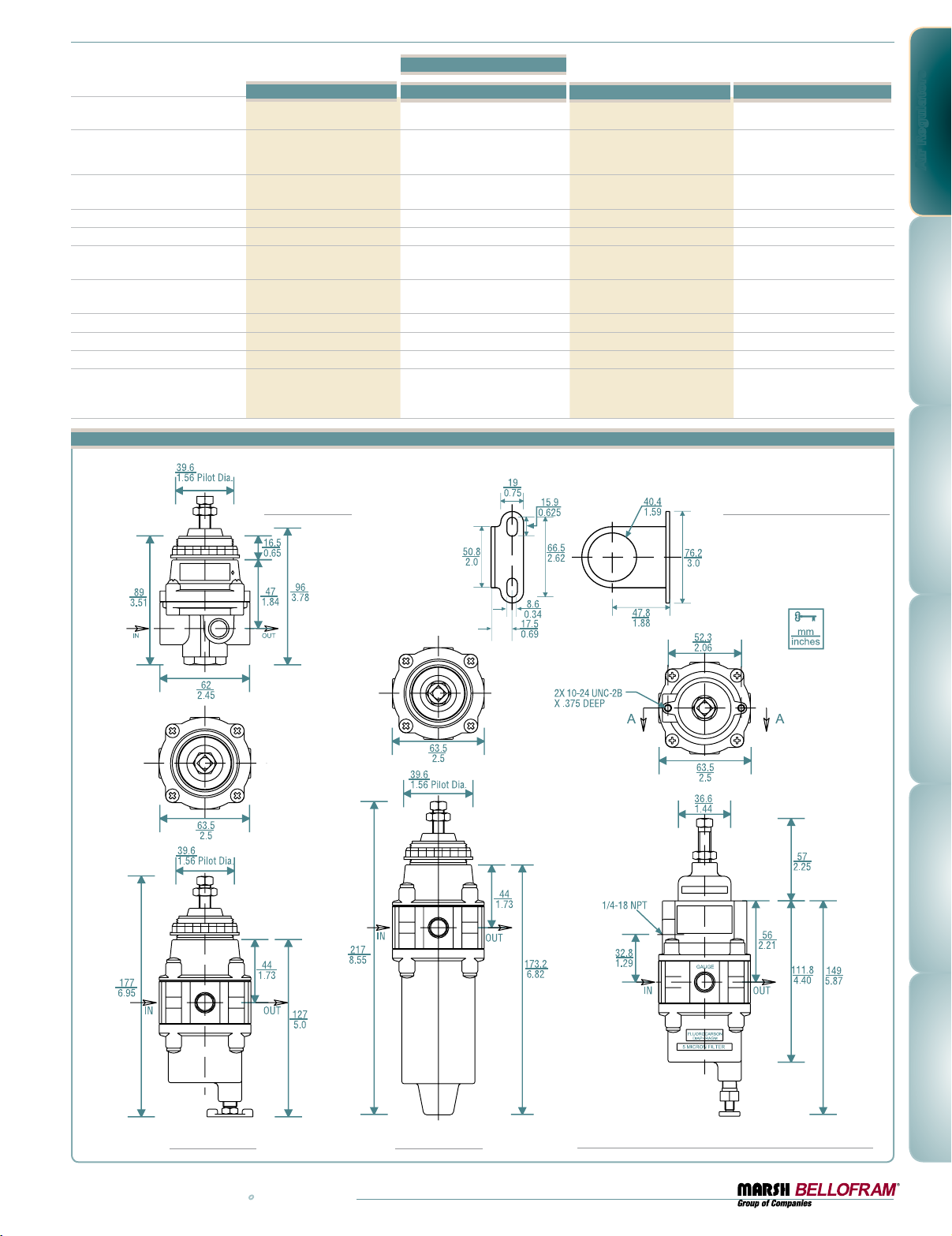
Type 51R, 51FR, 51AFR and 51FRCT Dimensional Drawings
Type 51FRCT Corrosive Tec
0-30 PSIG (0-2.1 BAR)
0-60 PSIG (0-4.1 BAR)
0-120 PSIG (0-8.3 BAR)
0.45 PSIG (0.03 BAR)
output change
20 SCFM
(566 LPM)
0.1 SCFM
(2.8 LPM)
Aluminum, Stainless Steel, Inconel,
Buna-N / polyester, Fluorocarbon,
acetal, polyphenylene sulfide
Type 51FRWT
0-30 PSIG (0-2.1 BAR)
0-60 PSIG (0-4.1 BAR)
0-120 PSIG (0-8.3 BAR)
0.45 PSIG (0.03 BAR)
output change
20 SCFM
(566 LPM)
0.1 SCFM
(2.8 LPM)
Aluminum, Plated Steel,
Acetal Resin, Buna-N /Polyester,
Music Wire
Air Regulators
Type 51R
Mounting Bracket
For T-51FR, T-51AFR and T-51R
607-000-104
Type 51FR
www.marshbellofram.com • 800.727.5646
Type 51AFR
Type 51FRCT & Type 51FRW T
17
Page 18
Air Regulators
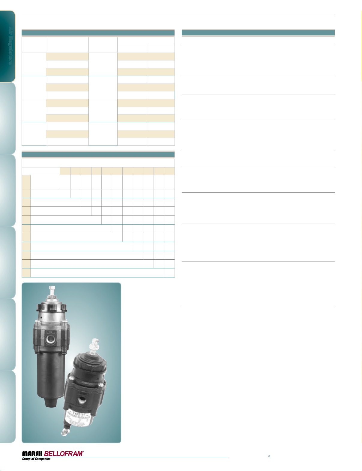
Type 51 Ordering Information
Set Point Range
BAR psig
0-2.1 0-30
T51R
Part Number
Port Size
(NPT)
960-222-000
960-223-000 0-4.1 0-60
1/4
960-224-000 0-6.9 0-100
T51FR
960-175-000
960-176-000 0-4.1 0-60
1/4
0-2.1 0-30
960-177-000 0-6.9 0-100
T51AFR
960-284-000
960-285-000 0-4.1 0-60
1/4
0-2.1 0-30
960-286-000 0-6.9 0-100
T51 FRCT
960-303-000
960-304-000 0-4.1 0-60
1/4
0-2.1 0-30
960-305-000 0-8.3 0-120
Type 51 Option Ordering Matrix
Replace last three digits of part number with digits from table below.
Option
Fluorocarbon
1
Pintle
2
Non-Relieving 002 032 042 052 062 072 082 092 112
3
Knob 003 043 053 063 073 083 10 3 113
4
5 Micron Filter 004 054 074 084 094 104 114
5
Epoxy Finish 005 065 075 085 095 10 5 115
6
Coalescing Filter (Type 51AFR only) 006 076 086 096 106 116
7
Mounting Bracket 007 087 097 107 117
8
Pressure Gauge 008 098 10 8 118
9
Tamper-Resistant Cover 009 109 119
10
Soft Relief Seat 010 110
11
Fluorocarbon Diaphragm 011
12345678910 11
001 02 1 031 041 051 061 071 081 091 101 111
T51 AFR
Type 51 Regulator Options and Accessories
Non-Relieving
Used in applications where it is desirable to relieve pressure downstream
and not at the regulator. Non-relieving regulators should not be used for
low or no flow applications.
Knob
Replaces the standard square head adjusting screw. (except Type 51FRCT)
5 Micron Filter
Replaces the 40 micron filter for more complete air filtration.
(Except Type 51R)
Epoxy Finish
An epoxy paint applied to the body and dripwell of the regulator exterior
surfaces to provide increased corrosion resistance. (Standard for Type
51FRCT)
Mounting Bracket
Plated steel bracket for side mounting. (316 SS for Type 51FRCT)
Coalescing Filter
Replaces the 40 micron filter for both moisture and particulate filtration.
(Type 51AFR only)
Pressure Gauge
Dual scale (psi/kPa) 2" (50mm) gauges. Ranges include 0-60 psi (0-4.1
BAR), 0-100 psi (0-6.9 BAR) and 0-120 psi (0-8.3 BAR). When specified
with regulator, the correct range will be supplied.
Fluorocarbon Elastomers
Diaphragm, as well as gaskets and O-rings, are made with a special elastomer to prevent deterioration from elements in the air supply, such as
flame retardant synthetic lubricants normally destructive to the standard
BUNA-N material.
Tamper Resistant Cover
A 316 stainless steel hexagonal cover placed over the adjusting screw
and threaded onto the bonnet of the regulator with a wrench, prevents
ordinary hand adjustments. Supplied with an O-ring that is designed to
seal the adjusting screws threads in captured bleed applications.
(T-51FRCT Only)
Low Bleed Diaphragm (Soft Relief Seat)
Used in applications where it is desirable to minimize the standard
bleed rate of the regulator while maintaining the ability to relieve excess
pressure at the regulator. Bleed rate is reduced from less than 6 SCFH
(2.8 LPM) to less than 0.1 SCFH (0.05 LPM). (Type 51FRCT only)
18
T51 FR
800.727.5646 • www.marshbellofram.com
Page 19
Type 51 Stainless Steel
Pressure Regulator Series
Features
•Ideal for sour gas and corrosive applications
or environments
•Excellent stability and repeatability
•Low droop
•Tapped vent for exhaust gas capture
•Built-in filter assemblies and dripwells
•Manual or automatic drain options
•Filter only assemblies available
•Panel, bracket or pipe mounting
Description
The Type 51SS regulator product line is
designed for service with a wide variety of
corrosive gases and environments. Special
construction features include 316 stainless
steel for the housing and filter assemblies,
with fluorocarbon elastomers used for the control diaphragm and the supply valve.
These corrosion resistant materials are compatible with sour gas and for use in off-shore environments. Typical applications include petrochemical processing, chemical plants, food processing
and paper/pulp mills.
This ruggedly built regulator operates in pressure ranges up to 150 PSIG (10.3 BAR). The Type
51SSFR and Type 51SSAR Regulators and the Type 51SSF and Type 51SSAF filter assemblies
have built-in dripwells which trap water, oil and other contaminants. The contaminants are easily
flushed out of the dripwell via a convenient
manual or automatic drain valve. The 40-48 Micron Filter is constructed of sintered 316 stainless
steel, and is easily removed.
The Type 51SS products can be through-panel
mounted with the mounting nut supplied (regulators only), bracket-mounted using the optional
bracket (regulators only), or pipe mounted by its
ports (regulators and filters).
The regulators and filter assemblies comply with
NACE material requirement #MR-01-75 for sulfide
stress cracking resistant metallic material for oil
field equipment.
Air Regulators
Type 51 SS
Pressure Regulator Series
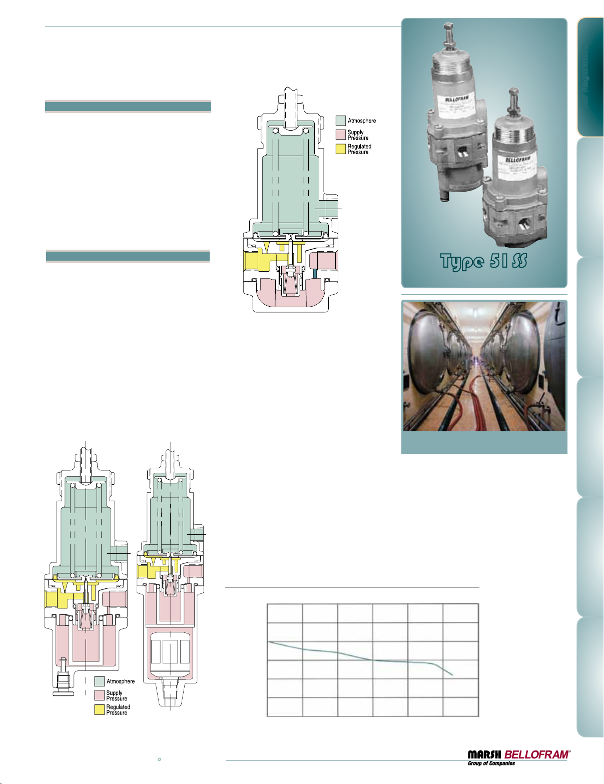
Once set to a desired pressure, the
Marsh Bellofram Type 51 Stainless
Steel Regulators maintain their
settings permanently.
The integral convoluted diaphragm
provides constant adjustment to
downstream pressure drop,
downstream pressure increase
and changes in forward flow.
www.marshbellofram.com • 800.727.5646
Type 51SS: Regulated Pressure VS. Flow
PSIG BAR
30 2.1
25 1. 7
20 1. 4
15 1.0
10 0.7
Regulated PRessuRe
5 0.3
0 0
SCFM 0 5 10 15 20 25 30
LPM 0 142 283 425 566 708 850
0-30 PSIG (0-2.1 BAR) Range, 100 PSIG (6.9 BAR) Supply
oRwaRd Flow
F
19
Page 20
Air Regulators
Filter
Maximum Supply Pressure
Output Pressure Range
Supply Pressure Sensitivity
@ 25 psig / 1.7 BAR change
in supply
Sensitivity
Repeatability
Flow @ 100 psig (6.9 BAR)
Supply 20 psig (1.4 BAR)
outlet
Exhaust Capacity
@ 5 psig (0.34 BAR) above
setpoint
Temperature Range
Air Consumption
Port Size
Materials of Construction
Type 51SSR Type 51SSFR Type 51SSAR Auto Filter Type 51SSF Type 51SSAF
n/a
250 PSIG (17.3 BAR) 250 PSIG (17.3 BAR) 250 psig (17.3 BAR) 250 PSIG (17.3 BAR) 250 PSIG (17.3 BAR)
0-30 PSIG (0-2.1 BAR)
0-60 PSIG (0-4.1 BAR)
0-100 PSIG (0-6.9 BAR)
2-150 PSIG (0.1-10.3 BAR)
0.20 PSIG (0.01 BAR )
output change
1" (2.5 cm) of water 1" (2.5 cm) of water 01" (2.5 cm) of water N/A N/A
0.1 PSIG (0.01 BAR) 0.1 PSIG (0.01 BAR) 0.1 PSIG (0.01 BAR) N/A N/A
20 SCFM
(566 LPM)
0.1 SCFM
(2.8 LPM)
-0 to 180˚F (-18 to 82˚C) -0 to 180˚F (-18 to 82˚C) 0 to 180˚F (-18 to 82˚C) 0 to 180˚F (-18 to 82˚C) 0 to 180˚F (-18 to 82˚C)
6 SCFH (2.84 LPM) Maximum 6 SCFH (2.84 LPM) Maximum 6 SCFH (2.84 LPM) Maximum N/A N/A
1/4 NPT or 3/8 NPT 1/4 NPT or 3/8 NPT 1/4 NPT or 3/8 NPT 1/4 NPT or 3/8 NPT 1/4 NPT or 3/8 NPT
316 Stainless Steel
housing and screen
fluorocarbon elastomers
Built in 40 micron filter
with manual drain
0-30 PSIG (0-2.1 BAR)
0-60 PSIG (0-4.1 BAR)
0-100 PSIG (0-6.9 BAR)
2-150 PSIG (0.1-10.3 BAR)
0.45 PSIG (0.03 BAR)
output change
20 SCFM
(566 LPM)
0.1 SCFM
(2.8 LPM)
316 Stainless Steel
housing and filter assemblies
fluorocarbon elastomers
Built in 40 micron filter
with auto-drain
0-30 PSIG (0-2.1 BAR)
0-60 PSIG (0-4.1 BAR)
0-100 PSIG (0-6.9 BAR)
2-150 PSIG (0.1-10.3 BAR)
0.45 PSIG (0.03 BAR)
output change
20 SCFM
(566 LPM)
0.1 SCFM
(2.8 LPM)
316 Stainless Steel
housing and filter assemblies
fluorocarbon elastomers
40 micron filter
N/A N/A
N/A N/A
N/A N/A
N/A N/A
316 Stainless Steel
housing and filter
assemblies fluorocarbon
elastomers
40 micron filter
316 Stainless Steel
housing and filter
assemblies fluorocarbon
elastomers
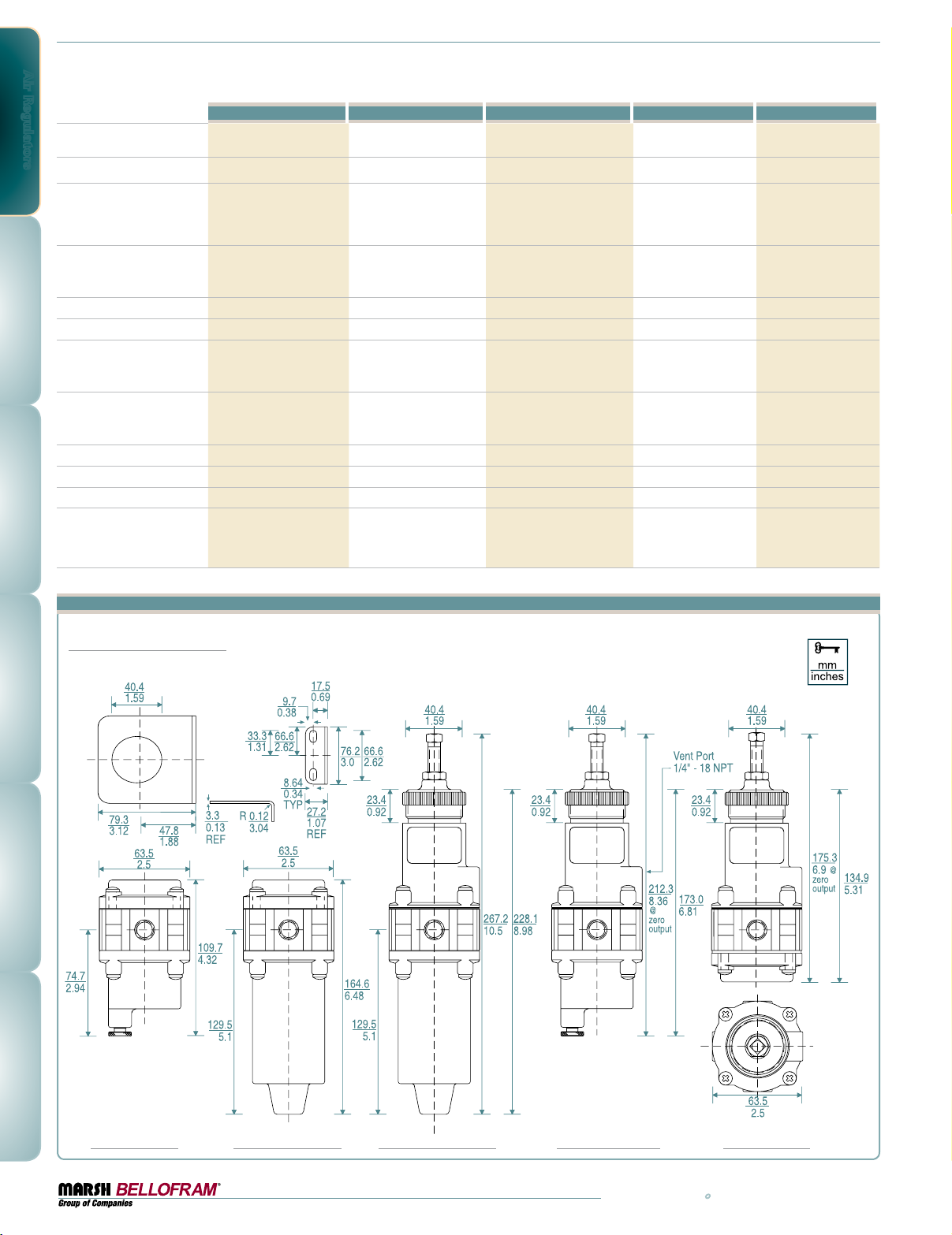
Dimensional Drawings
Mounting Bracket
607-000-128
20
Type 51SSF Type 51SSAF
Type 51SSAR
Type 51SSFR
Type 51SSR
800.727.5646 • www.marshbellofram.com
Page 21
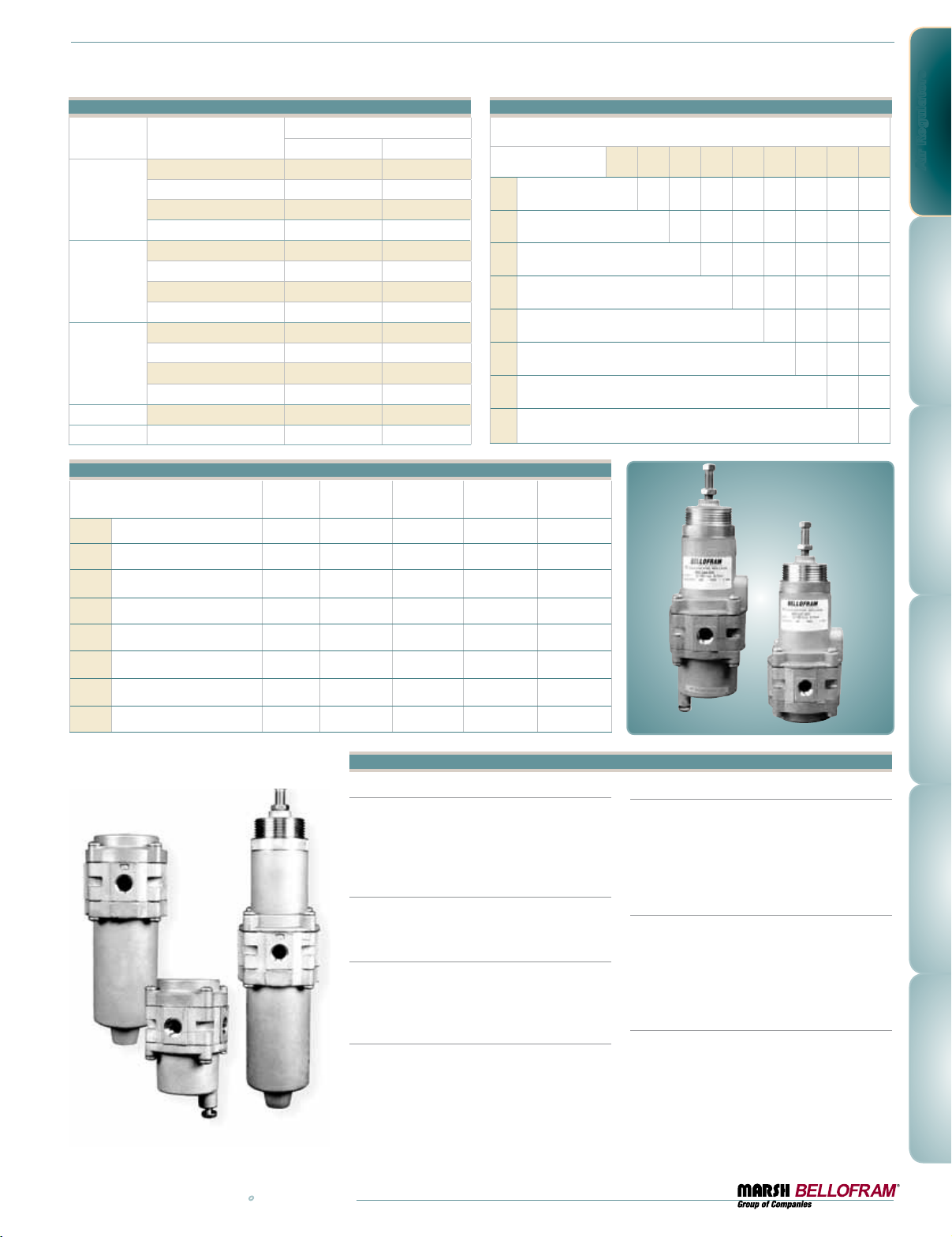
Type 51SS Ordering Information
Part Number
960-245-000 0-2.1 0-30
51SSR
960-246-000 0-4.1 0-60
960-247-000 0-6.9 0-100
960-248-000 0.1-10.3 2-150
960-242-000 0-2.1 0-30
51SSFR
960-243-000 0-4.1 0-60
960-244-000 0-6.9 0-100
Set Point Range
BAR psig
Type 51SS Option Ordering Matrix
Replace last three digits of part number with digits from table below.
Option
Non-Relieving 002 032 042 072 082 092 112
2
Socket Head Build Screw 003 043 073 083 093 103 113
3
5 Micron Filter 004 074 084 094 10 4 11 4
4
Mounting Bracket 007 0 87 097 107 117
7
960-241-000 0.1-10.3 2-150
Pressure Gauge 008 098 10 8 118
960-249-000 0-2.1 0-30
51SSAR
960-250-000 0-4.1 0-60
960-251-000 0-6.9 0-100
960-252-000 0.1-10.3 2-150
51SSF 960-253-000 – –
51SSAF 960-254-000 – –
8
Tamper-Resistant Cover 009 10 9 11 9
9
Low Bleed 010 11 0
10
3/8 NPT Port 011
11
Options
•=optionisavailable
Non-Relieving •• •
2
Socket Head Build Screw
3
5 Micron Filter ••• •
4
Mounting Bracket •• •
7
Pressure Gauge •• • • •
8
Tamper Resistant Cover •• •
9
T-51SSR T-51SSFR T-51SSAR T-51SSF T-51SSF
•• • • •
123478910 11
T51 SSFR
T51 SSR
Air Regulators
Low Bleed •• •
10
3/8" Port •• • • •
11
Regulator Options and Accessories
Non-Relieving
Used in applications where it is desirable to
relieve pressure downstream and not at the
regulator. Non-relieving regulators should not
be used for low or no flow applications.
Socket Head Build Screw
Socket head build screws are provided in place
of phillips drive screws.
5 Micron Filter
Replaces the 40 micron filter for more complete
air filtration. (Except Type 51SSR)
P/N 836-000-002
Mounting Bracket
316 Stainless Steel bracket for side mounting.
P/N 607-000-128
Pressure Gauge
Dual scale (PSI / kPa) 2-1⁄2" (63mm) gauges.
Ranges include 0-60 PSI (0-410 kPa), 0-100 PSI
(0-690 kPa) and 0-200 PSI 0-1400 kPa). When
specified with regulator, the correct range will
be supplied.
Tamper Resistant Cover
A 316 stainless steel hexagonal cover placed
over the adjusting screw and threaded onto the
bonnet of the regulator with a wrench, prevents
ordinary hand adjustments.
Low Bleed Diaphragm
(Soft Relief Seat)
Used in applications where it is desirable to
minimize the standard bleed rate of the regulator while maintaining the ability to relieve
excess pressure at the regulator. (Bleed rate
is reduced from less than 6 SCFH (2.8 LPM)
to less than 0.1 SCFH (0.05 LPM).
www.marshbellofram.com • 800.727.5646
21
Page 22
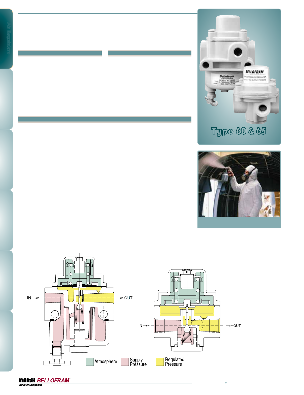
Air Regulators
Type 60 & Type 65
Pre-set Pressure Regulators
Type 60
Features
•Pre-Set, ideal for OSHA regulations
•Superior regulation characteristics
•Rugged, corrosion-resistant construction
•Excellent stability and repeatability
•Self-relieving
•Low droop at high flow
•Several mounting options
•Low cost
Description
Marsh Bellofram’s General Purpose Type 60
and Type 65 Precision Air Regulators are reliable precision units designed for instrumentation and general purpose use. The Type 60 is a
pre-set, fixed-pressure unit with a dripwell.
The Type 65 is similar to the Type 60, but
without a dripwell.
Test data for these regulators show excellent
performance characteristics compared with
those of similar units presently on the market.
These Marsh Bellofram regulators are generally superior in regulated pressure vs. flow,
forward-to-reverse flow offset, supply pressure
sensitivity, repeatability and stability.
Ruggedly designed and constructed, the regulators have housings of diecast aluminum. Both
models are finished with vinyl paint (which
resist scratching, weathering and other physical
abuse), and are pressure and leak tested prior
to shipment from the factory.
Applications
The design of these regulators is especially
well suited to pilot-operated controllers, and
instruments, as well as applications such as air
chucks, air spray guns, air cylinders and actuators, and a wide range of industrial pneumatic
systems and equipment.
Careful design and quality materials throughout
assure long, trouble-free operation in the most
difficult industrial environments. A rubberized,
soft-seat valve stem provides positive shut-off
and “forgives” dirt or other foreign matter. An
aspirator maintains downstream pressure and
compensates for droop when high flow occurs.
The gauge port is convenient for gauge installation and can also be used as an additional
full flow outlet. The Type 65 regulator has a
60-mesh 304 stainless steel screen to block
foreign particles from entering the output
stream. The Type 60 regulator has a unique
self-cleaning nylon 40 micron mesh filter that
can be easily removed. Type 60 and Type 65
tamper resistant regulators meet OSHA requirements for air supplied to hand-held air guns
(if preset to 30 psig).
Type 65
Type 60 & 65
Pressure Regulator Series
22
800.727.5646 • www.marshbellofram.com
Page 23
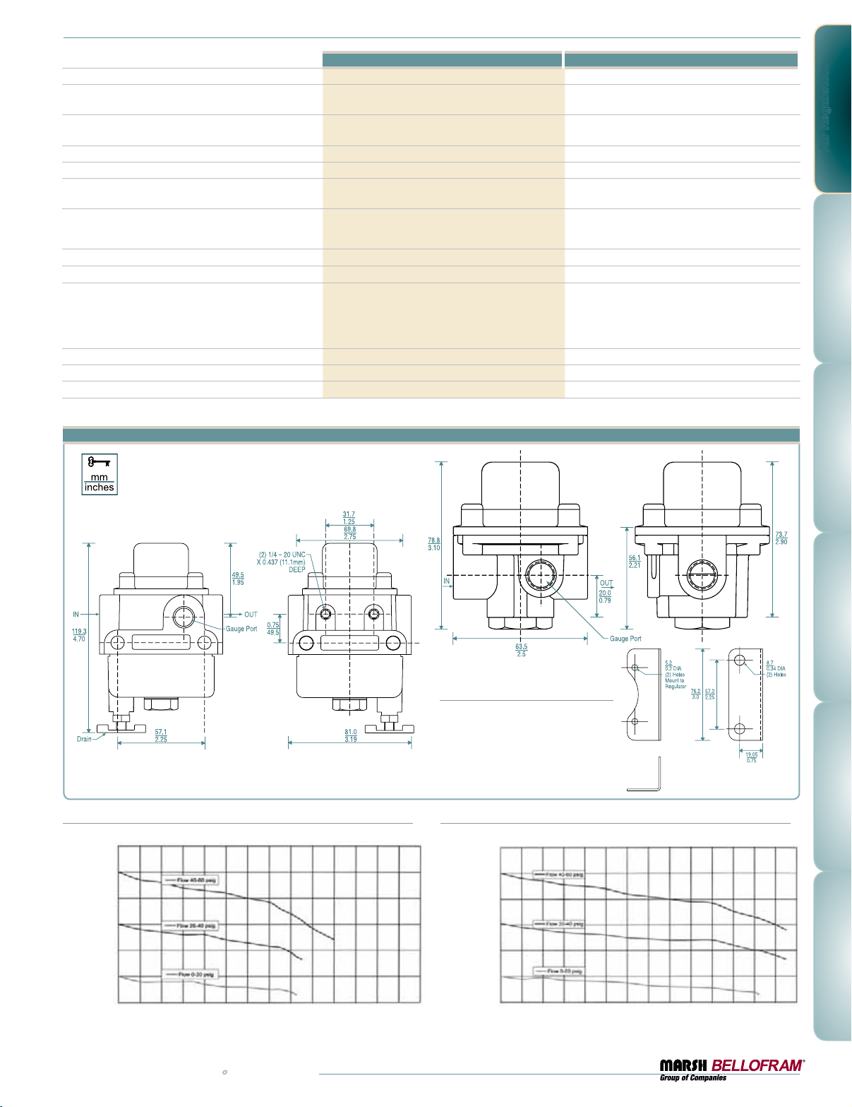
Sensitivity
Flow @ 100 PSIG (6.9 BAR)
Supply 20 PSIG (1.4 BAR) outlet
Effect of Supply Pressure variation
(25 PSIG) on Outlet Pressure
Exhaust Capacity@ 5 psig above 20 PSIG setpoint
Maximum Supply Pressure
Effect of Changes in Flow on Regulated Pressure
(100 PSIG/6.9 BAR Supply)
Output Pressure Range
Total Air Consumption @ Maximum Output
Port Size
Materials of Construction
Diaphragm: Buna-N elastomer with polyester fabric
Size
Weight
Mounting
Type 60 and Type 65 Dimensional Drawings
Type 60 Type 65
1" (2.5 cm) Water Column 1" (2.5 cm) Water Column
20 SCFM
(566 LPM)
< 0.2 PSIG (0.01 BAR)
for 25 PSIG (1.7 BAR)
0.1 SCFM (2.8 LPM) 0.1 SCFM (2.8 LPM)
250 PSIG (17.3 BAR) 250 PSIG (17.3 BAR)
3 PSIG (0.2 BAR) for 10 SCFM ( 283 LPM)
(1/4 NPT, 20 PSIG / 1.4 BAR set point)
0-20 PSIG (0-1.4 BAR)
20-40 PSIG (1.4-2.8 BAR)
40-60 PSIG (2.8-4.1 BAR)
6 SCFH (2.84 LPM) Maximum 6 SCFH (2.84 LPM) Maximum
1/4 NPT, BSPT 1/4 NPT, BSPT
Body: Diecast aluminum with vinyl paint
Adjusting Screw: Plated steel
Trim: Plated steel, brass, acetal resin
Spring: Music wire
3.19" X 3.19" X 4.70" (81 X 81 X 119 mm) 2.5" X 2.5" X 3.13"
1.59 lb. (0.7 kg) 0.69 lb. ( 0.3 kg)
Pipe, Bracket or Thru Body Holes Pipe or Bracket
Type 65
3 PSIG (0.2 BAR) for 10 SCFM (283 LPM)
(1/4 NPT, 20 PSIG / 1.4 BAR set point)
Body: Diecast aluminum with vinyl paint
Trim: Plated steel, brass, acetal resin
Diaphragm: Buna-N elastomer with polyester fabric
20 SCFM
(566 LPM)
< 0.2 PSIG (0.01 BAR)
for 25 PSIG (1.7 BAR)
0-20 PSIG (0-1.4 BAR)
20-40 PSIG (1.4-2.8 BAR)
40-60 PSIG (2.8-4.1 BAR)
Adjusting Screw: Plated steel
Spring: Music wire
Air Regulators
Type 60
Type 60: Regulated Pressure VS. Flow
PSIG BAR
60 4.1
50 3.4
40 2.8
30 2.1
20 1. 4
Regulated PRessuRe
10 0.7
0 0
SCFM 0 2 4 6 8 10 12 14 16 18 20 22 24 26 28
LPM 0 57 113 170 2 27 28 3 340 397 453 510 566 623 680 736 793
FoRwaRd Flow
Optional Mounting Bracket
607-000-057
Type 65: Regulated Pressure VS. Flow
PSIG BAR
60 4.1
50 3.4
40 2.8
30 2.1
20 1. 4
Regulated PRessuRe
10 0.7
0 0
SCFM 0 2 4 6 8 10 12 14 16 18 20 22 24 26 28
LPM 0 57 11 3 17 0 227 283 340 3 97 453 510 566 6 23 680 73 6 793
FoRwaRd Flow
www.marshbellofram.com • 800.727.5646
23
Page 24
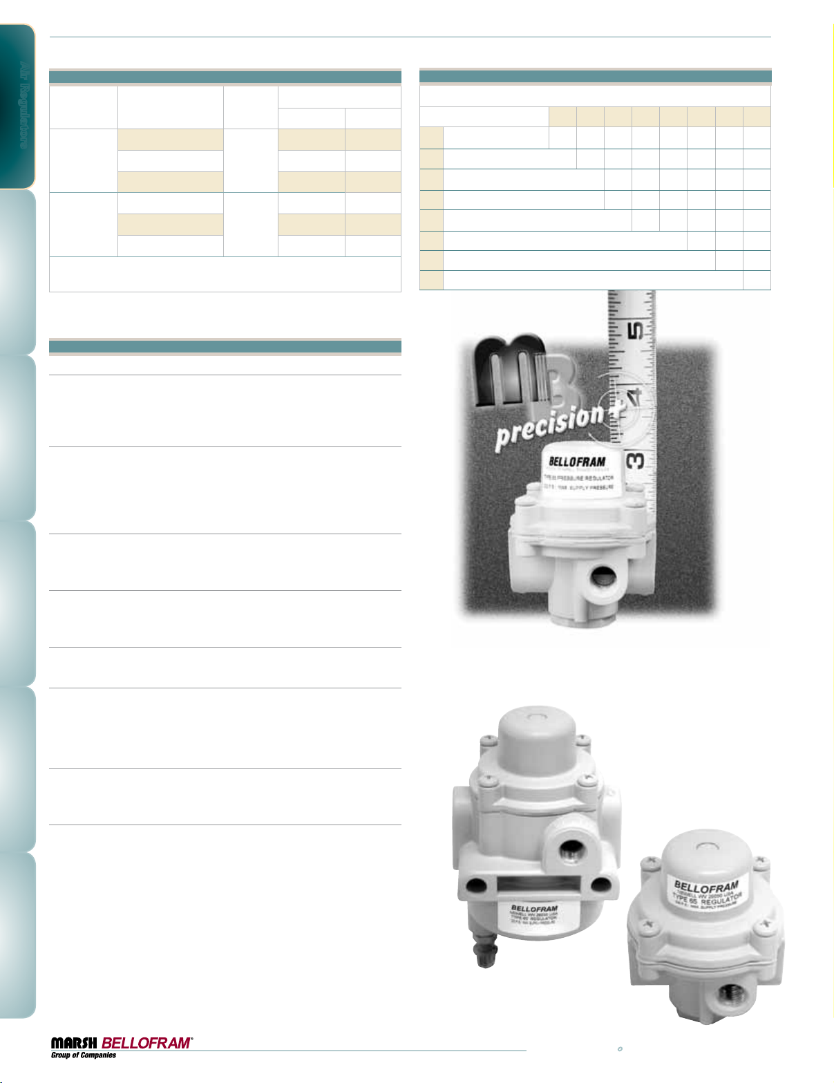
Air Regulators
Type 60 and Type 65 Ordering Information
Set Point Range
BAR PSIG
0-1.4 0-20
Type 60
Part Number
Port Siz e
(NPT)
960-070-000
960-109-000 1.4-2.8 20-40
1/4
960-110-000 2.8-4.1 40-60
Type 65
960-071-000
960-150-000 1.4-2.8 20-40
1/4
0-1.4 0-20
960-151-000 2.8-4.1 40-60
NOTE: Because the Types 60 and 65 are preset at the factory, it is necessary to
provide the supply pressure and preset pressure setting when ordering.
Options and Accessories:
Fluorocarbon Pintle
A special elastomeric pintle used where elements in the supply air, such
as flame retardant synthetic lubricants, are particularly destructive to
ordinary pintle material.
Non-Relieving
Used in applications where it is desirable to relieve pressure downstream
of the regulator, for some constant flow applications, and where the gas
flowing through the regulator must not escape at the regulator. Non-relieving regulators should not be used for low or no flow applications.
5 Micron Filter
Replaces the 40 micron filter supplied with the standard Type 60 for more
complete air filtration. P/N 677-000-002
Corrosive Resistant Epoxy Finish
An epoxy paint applied to the body, bonnet and dripwell of the regulator
exterior surfaces to provide increased corrosion resistance.
Mounting Bracket
Steel (dichromate finish) bracket for side mounting. P/N 607-000-057
Pressure Gauge
Dual scale 2 in. (50.8 mm) gauges.
When specified with a regulator, the correct range will be supplied.
(NPT versions only)
Soft Relief Seat
Used in applications where it is desirable to reduce the standard bleed
rate from 6 SCFH (2.83 LPM) to less than 0.1 SCFH (0.05 LPM).
Fluorocarbon Diaphragm
Diaphragm as well as all seals are made of fluorocarbon elastomer to
prevent deterioration from elements in the air supply, such as flame
retardant synthetic lubricants normally destructive to standard Nitrile
material.
To order BSPT add “BSPT” to end of part number.
Type 60 and Type 65 Option Ordering Matrix
Replace last three digits of part number with digits from table below.
Option
1
Fluorocarbon Pintle 0 01 021 0 41 051 071 0 81 101 111
2
Non-Relieving 002 042 052 072 082 112
4
5 Micron Filter (Type 60 only) 004 054 074 084 104 114
5
Epoxy Finish 005 075 085 105 115
7
Mounting Bracket 007 087 107 117
8
Pressure Gauge 008 108 118
10
Soft Relief Seat 010 11 0
11
Fluorocarbon Diaphragm 011
The Type 65 small stature makes
it ideal for compact applications
12457810 11
24
800.727.5646 • www.marshbellofram.com
Page 25
Type 70
Type 70BP
High Flow
Pressure Regulator
Features
•High flow capacity - Up to 80 SCFM
(2266 LPM)
•Responds quickly to minute changes
in downstream pressure
•Dampening action of aspirator tube
maintains downstream pressure
•Balanced supply valve minimizes the effect
of supply pressure changes
•Bellofram’s Buna-N and polyester rolling
diaphragms are designed to give millions
of cycles
•Honking and buzzing eliminated by action
of integral baffle and aspirator tube
•Stack up construction can be
disassembled and serviced without
removal from air line
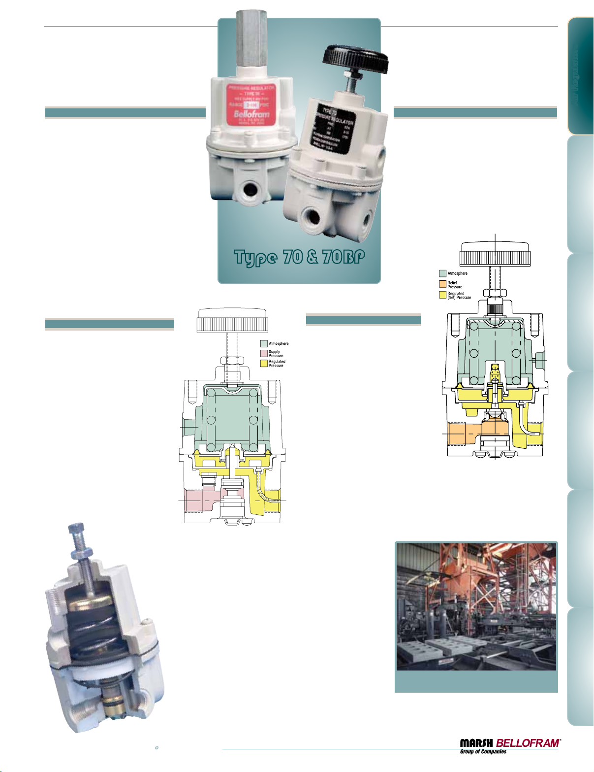
Type 70 Description
The Type 70 Regulator is specifically
designed for applications that require
substantial flow capacity and accurate
pressure controls. Flows of 80 SCFM
(2250 LPM) can be attained.
Downstream pressure can be set
within 0.25 in. (6.3mm) of water
column and is accurately maintained
under varying flow conditions with the
help of an aspirator tube which adjusts
the air supply in accordance with the
flow velocity. A balanced supply valve,
utilizing a rolling diaphragm, makes
the regulator virtually immune to
changes in supply pressure.
The Type 70 has a
rugged precision
die cast aluminum
housing, and is pressure-tested and chromate-
treated for internal corrosion resistance.
The regulator housing is finished with vinyl
paint which resists scratching, weathering
and other physical abuse.
High Flow Back
Pressure Regulator
Air Regulators
Features
•High flow Capacity - Up to 50 SCFM
(1400 LPM)
•Responds quickly to minute changes in
upstream pressure
•Bellofram’s Buna-N and polyester rolling
diaphragms are designed to give
millions of cycles
•Stack up construction can be disassembled
and serviced without removal from air line
Type 70 & 70BP
Pressure Regulator Series
Type 70BP Description
The Type 70 Back Pressure
Regulator functions as a high
flow, high precision pneumatic
relief valve with an adjustable
setpoint. The Type 70BP can be
used in place of a standard relief
valve to improve pressure control
while maintaining protection
against over pressurization, as in
supply pressure lines to instruments and other control devices.
It is most often used in conjunction with a diaphragm-operated
valve and bleed orifice as a compressor controller. Excess compressor
pressure is relieved through the regulator to actuate the intake restricting
valve. When the regulator is shut off, downstream air escapes through
the bleed orifice, allowing the restricting valve to open.
www.marshbellofram.com • 800.727.5646
Contact Us About
NACE Compatible
T70 Regulator
"No Yellow Metals"
25
Page 26
Air Regulators
Sensitivity
Flow Capacity
Effect of Supply Pressure variation
(25 psig) on Outlet Pressure
Exhaust Capacity (5 above psig 20 psig set point)
Maximum Supply Pressure
Effect of Changes in Flow on Regulated Pressure
(100 psig/6.9 BAR Supply)
Output Pressure Ranges (Type 70)
Set Point Ranges (Type 70BP)
Total Air Consumption @ Maximum Output
Temperature Range
Port Size
Materials of Construction
Size
Weight
Preset Pressure
Tamper Resistant Cover
Mounting
Type 70 Type 70BP
1/4" (6.4 mm) Water Column 1/8" (3.2 mm) Water Column
40 (1113 LPM)
50 (1416 LPM)
or 80 SCFM (2266 LPM)
< 0.025 PSIG (1.7 BAR) N/A
4 SCFM (113 LPM) N/A
250 PSIG (17.2 BAR) 250 PSIG (17.2 BAR)
2.5 PSIG (0.2 BAR) over flow 50 SCFM (1416 LPM)
(3/8 NPT, 0-30 PSIG / 0-2.1 BAR range,
15 PSIG / 1 BAR set point)
0-2 PSIG (0-0.1 BAR)
0-10 PSIG (0-0.7 BAR)
0-30 PSIG (0-2.1 BAR)
1-60 PSIG (0.1-4.1 BAR)
2-150 PSIG (0.1-10.3 BAR)
3-200 PSIG (0.2-13.8 BAR)
N/A
from 1.0 to 12.5 SCFH (0.5-6 LPM) N/A
-40˚ to 200˚F (-40˚ to 93˚C) -40˚ to 200˚F (-40˚to 93˚C)
1/4, 3/8, 1/2 NPT, BSPT 1/4, 3/8, 1/2 NPT, BSPT
Body: Diecast aluminum with vinyl paint
Adjusting Screw: Plated steel
Trim: Plated steel, brass, acetal resin
Diaphragm: Buna-N with polyester fabric
Knob: Phenolic plastic
Spring: Music wire
3.0" X 3.0" X 6.0" (76 X 76 X 152 mm) 3.0" X 3.0" X 6.0" (76 X 76 X 152 mm)
1.41 lb. (0.6 kg) 1.5 lb. (0.7 kg)
No No
Yes Yes
Pipe, panel, or bracket Pipe, panel, or bracket
50 SCFM (1416 LPM)
N/A
N/A
0-2 PSIG (0-0.1 BAR)
0-10 PSIG (0-0.7 BAR)
0-30 PSIG (0-2.1 BAR)
0-60 PSIG (0-4.1 BAR)
0-150 PSIG (0-10.3 BAR)
Body: Diecast aluminum with vinyl paint
Adjusting Screw: Plated steel
Trim: Acetal, brass, plated steel, nitrile
Diaphragm: Buna-N with polyester fabric
Knob: Phenolic plastic
Spring: Music wire
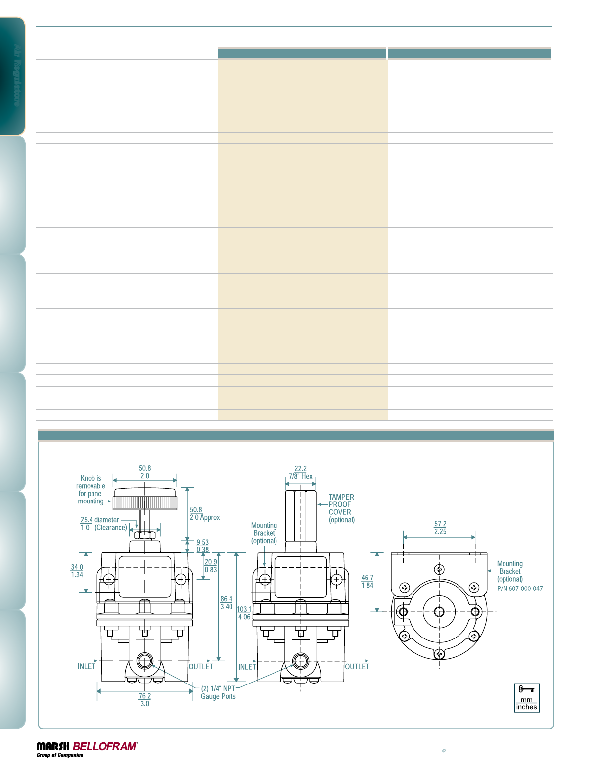
Type 70 and 70BP Dimensional Drawings
26
800.727.5646 • www.marshbellofram.com
Page 27
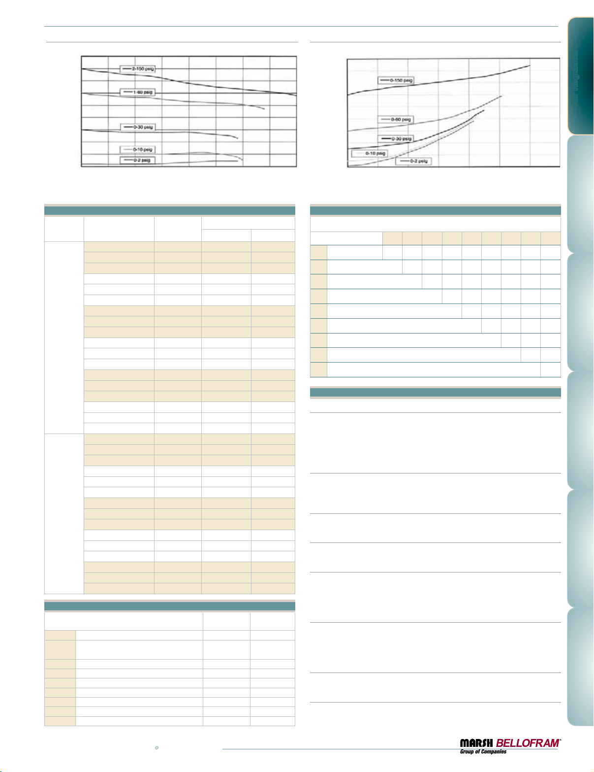
Type 70: Regulated Pressure VS. Flow
PSIG BAR
90 6.2
80 5.5
70 4.8
60 4.1
50 3.4
40 2.8
Regulated PRessuRe
30 2.1
20 1. 4
10 0.7
0 0
SCFM 0 10.0 20.0 30.0 40.0 50.0 60.0 70.0 80.0
LPM 0 300 575 850 1150 1400 17 00 2000 2265
oRwaRd Flow
F
Type 70 and 70BP Ordering Information
Part Number
Port Size
(NPT)
Set Point Range
BAR PSIG
960-129-000 1/4 0-0.1 0-2
960-174-000 3/8 0-0.1 0-2
960-162-000 1/2 0-0.1 0-2
960-130-000 1/4 0-0.7 0-10
960-131-000 3/8 0-0.7 0-10
960-163-000 1/2 0-0.7 0-10
960-089-000 3/8 0-2.1 0-30
960-090-000 1/4 0-2.1 0-30
T70
960-159-000 1/2 0-2.1 0-30
960-091-000 3/8 0.1-4.1 1-60
960-092-000 1/4 0.1-4.1 1-60
960-160-000 1/2 0.1-4.1 1-60
960-093-000 3/8 0.1-10.3 2-150
960-094-000 1/4 0.1-10.3 2-150
960-161-000 1/2 0.1-10.3 2-150
960-152-000 1/4 0.2-13.8 3-200
960-153-000 3/8 0.2-13.8 3-200
960-164-000 1/2 0.2-13.8 3-200
960-191-000 1/4 0-0.1 0-2
960-192-000 3/8 0-0.1 0-2
960-193-000 1/2 0-0.1 0-2
960-194-000 1/4 0-0.7 0-10
960-195-000 3/8 0-0.7 0-10
960-196-000 1/2 0-0.7 0-10
960-197-000 1/4 0-2.1 0-30
T70BP
960-198-000 3/8 0-2.1 0-30
960-199-000 1/2 0-2.1 0-30
960-200-000 1/4 0-4.1 0-60
960-201-000 3/8 0-4.1 0-60
960-202-000 1/2 0-4.1 0-60
960-203-000 1/4 0-10.3 0-150
960-204-000 3/8 0-10.3 0-150
960-205-000 1/2 0-10.3 0-150
Options
•=optionisavailable
s=optionisstandard
Non-Relieving •
2
Knob
3
Sq. Head Adj. Screw
Epoxy Coating ••
5
Tapped Vent
6
Mounting Bracket ••
7
Pressure Gauge ••
8
Tamper Resistant Cover ••
9
Low Bleed •
10
Check Valve •
11
TYPE 70 TYPE 70BP
s
•
•
s
•
Type 70BP: Regulated Pressure VS. Flow
PSIG BAR
90 6.2
80 5.5
70 4.8
60 4.1
50 3.4
40 2.8
30 2.1
Regulated PRessuRe
20 1. 4
10 0.7
0 0
SCFM 0 10.0 20.0 30.0 40.0 50.0 60.0 70.0
LPM 0 300 575 850 1150 1400 1700 2000
F
oRwaRd Flow
Type 70 and 70BP Option Ordering Matrix
Replace last three digits of part number with digits from table below.
Option
2
Non-Relieving 002 032 052 062 072 082 092 112
3
Sq. Head Adj. Screw 003 053 063 073 083 10 3 113
5
Epoxy Finish 005 065 075 085 095 10 5 11 5
6
Tapped Vent 006 076 086 096 106 11 6
7
Mounting Bracket 0 07 087 097 107 117
8
Pressure Gauge 008 098 10 8 118
9
Tamper-Resistant Cover 009 10 9 119
10
Low Bleed 010 11 0
11
Check Valve 011
235678910 11
Options and Accessories
Non-Relieving
Used in applications where it is desirable to relieve pressure downstream
of the regulator, for some constant flow applications, and where the gas
flowing through the regulator must not escape at the regulator. Non-relieving regulators should not be used for low or no flow applications.
Corrosive Resistant Epoxy Finish
An epoxy paint applied to the body of the regulator exterior surfaces to
provide increased corrosion resistance.
Tapped Vent
Allows installation of plumbing to capture exhaust air.
Mounting Bracket
Steel (dichromate finish) bracket for side mounting.
Pressure Gauge
Dual scale 2 in. (50.8 mm) gauges. Ranges include 0-30 PSIG (0-200 kPa),
0-60 PSIG (0-400 kPa), 0-100 PSIG (0-700 kPa) and 0-160 PSIG (0-1100
kPa). When specified with regulator, the correct range will be supplied.
Tamper Resistant Cover
An aluminum tubular cover placed over a slotted head adjusting screw
and screwed onto the bonnet of the regulator with a wrench. Prevents
ordinary hand adjustments.
Low Bleed
Reduces steady-state air consumption by approximately 50%.
Check Valve
Allows quick dumping of output line pressure through the supply air line
when the supply is shut down.
Air Regulators
www.marshbellofram.com • 800.727.5646
27
Page 28
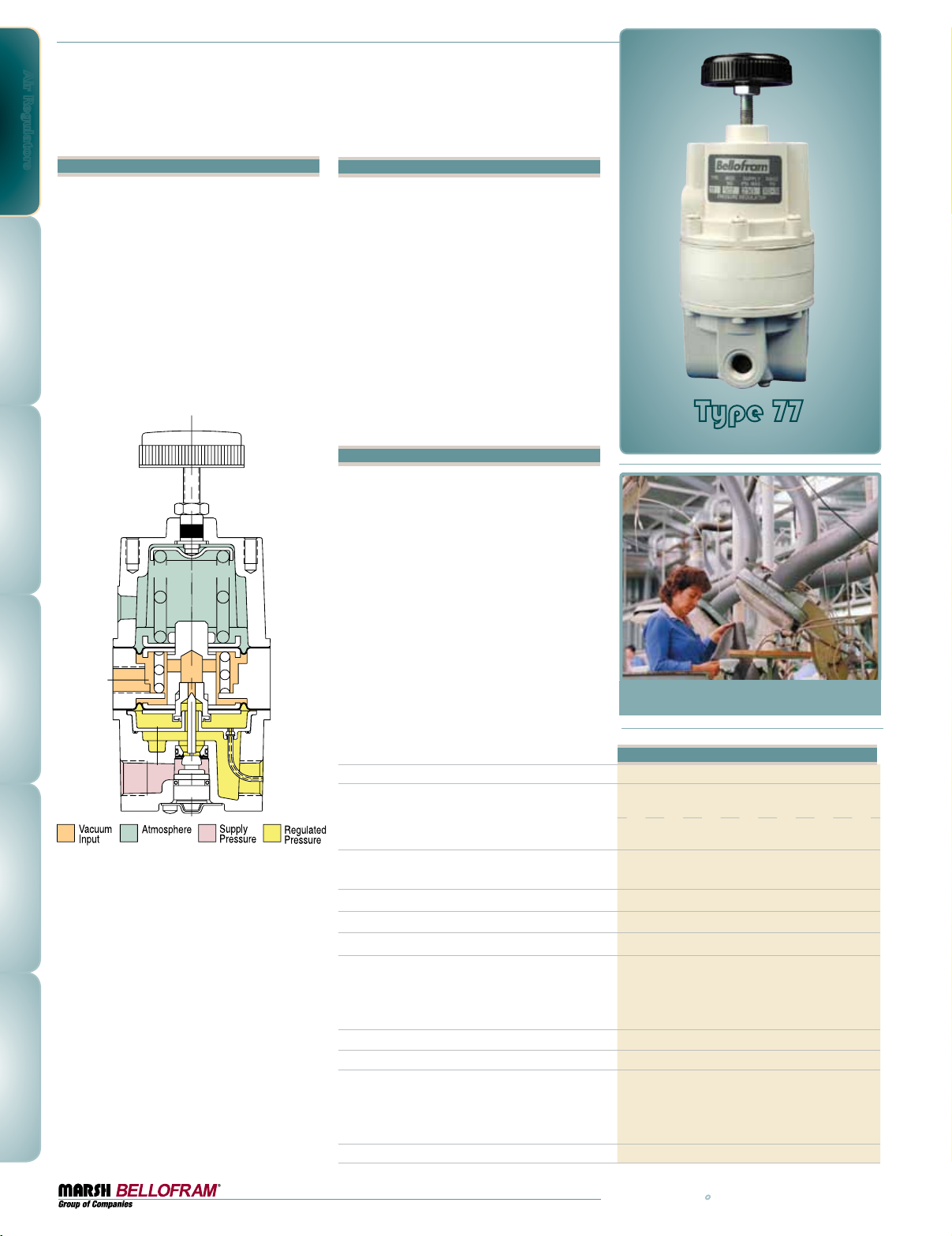
Air Regulators
Type 77
Vacuum Regulator Series
Features
•Single-unit control of pressures from 29" Hg
vacuum to 150 PSI
•Flow capacity up to 40 SCFM
•Dampening action of aspirator tube maintains
stable output pressure
•Output virtually unaffected by changes in
supply pressure
•Can be disassembled and serviced without
removing from line
Description
Bellofram’s Type 77 Vacuum Regulator incorporates a fixed negative 15 PSIG bias spring
to maintain vacuum outputs up to 29" Hg. An
adjustable opposing range spring increases
controlled pressure outputs up to 150 PSIG.
Output pressure droop under varying downstream flow conditions is minimized by use of an
aspirator tube which adjusts the air supply valve
opening in accordance with flow velocity. A
balanced supply valve, utilizing a reinforced rolling diaphragm, keeps regulator output virtually
immune to changes in supply pressure. Stack-up
construction makes the Type 77 easily serviceable, without removing it from the air line.
Applications
The Type 77 provides precise control in subatmospheric pressure applications. Specific uses
include sample collecting systems, air quality
monitoring, parts coating operations, and other
industrial functions requiring controlled system
pressure from 29" Hg vacuum to 150 PSIG.
The regulator may be installed either upstream
or downstream from the vacuum pump.
Upstream installation (Figure 1) is preferred
when rapid evacuation of a vessel or system is
required, because the exhaust capacity of the
pump is normally greater than that of the regulator. In all other applications, the regulator can
be located between the pump and the vessel.
(Figure 2)
Sensitivity
Flow Capacity
Effect of Supply Pressure variation
(25 psig/1.7 BAR) on Outlet Pressure
Exhaust Capacity@ 5 psig (0.34 BAR) above setpoint
Maximum Supply Pressure
Ambient Temperature Limits
Output Pressure Ranges
Total Air Consumption @ Maximum Output
Port Size
Materials of Construction
Mounting Options
Type 77
Vacuum Regulator Series
TYPE 77
1/2" (1.3 cm) Water Column
2.5 SCFM (71 L/M) @ 29" Hg
(740 mm Hg) Vacuum
40 SCFM (1130 L/M) @ 100 PSIG
(6.9 BAR) supply, 20 PSIG (1.4 BAR) output
Less than 0.1 PSIG (0.01 BAR)
4 SCFM (113 LPM)
250 PSIG (17.2 BAR)
-40 to 200˚F (-40 to 93˚C)
Vacuum to 2 PSIG (0.1 BAR)
Vacuum to 10 PSIG (0.7 BAR)
Vacuum to 30 PSIG (2.1 BAR)
Vacuum to 100 PSIG (6.9 BAR)
Vacuum to 150 PSIG (10.3 BAR)
6 SCFH (2.8 LPM)
1/4 NPT, 3/8 NPT, 1/4 BSPT, 3/8 BSPT
Body: Diecast Aluminum with Vinyl Paint
Trim: Stainless steel, Brass, Plated steel, Acetal and Buna-N
Diaphragm: Buna-N with Polyester Fabric
Knob: Phenolic Plastic
Spring: Music wire
Pipe, Panel or Bracket
28
800.727.5646 • www.marshbellofram.com
Page 29
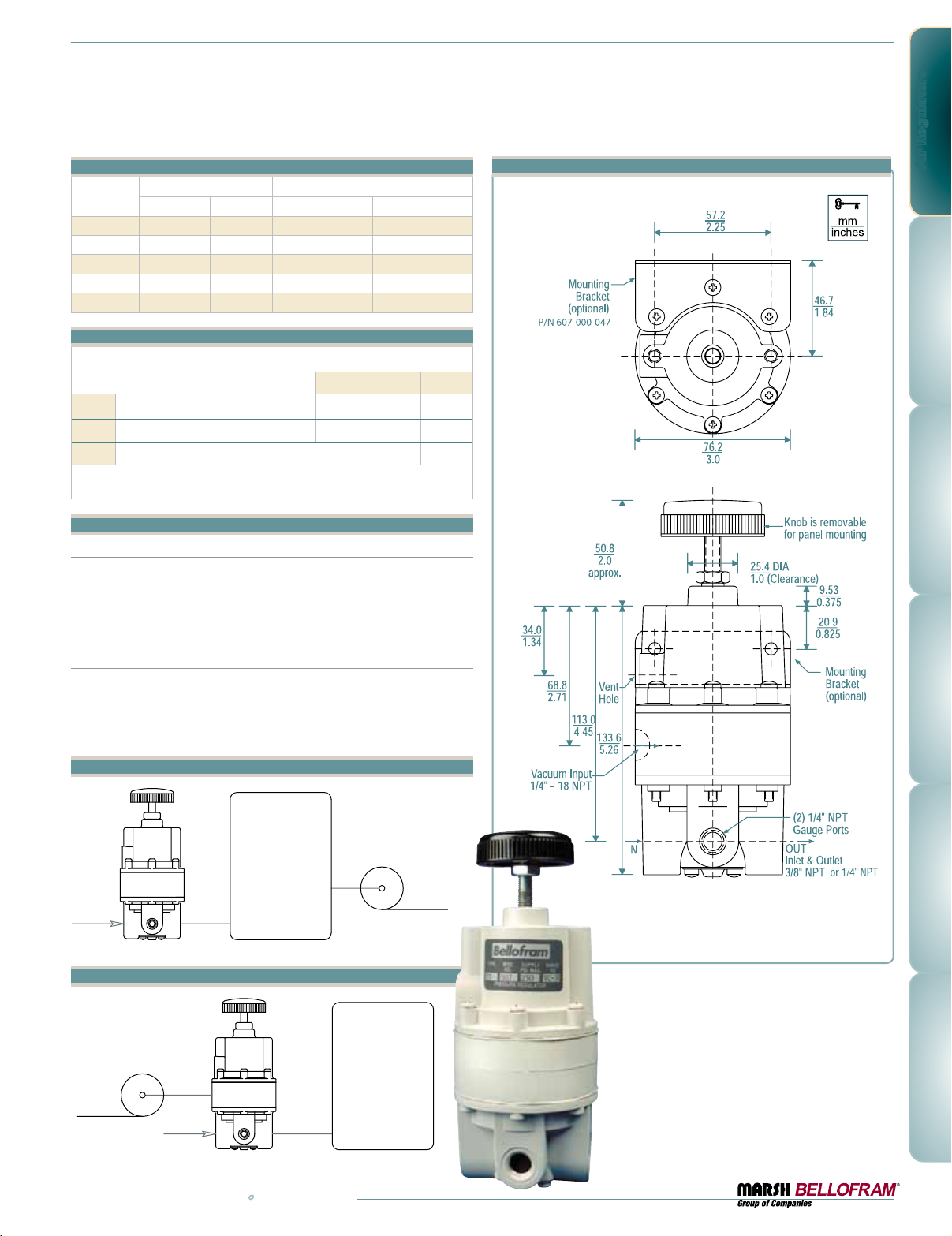
Type 77 Ordering Information
TYPE 77
VACUUM PUMP
SUPPLY
TYPE 77
TANK
FIGURE 1
T70
Range Part Number
BAR PSIG 1/4 NPT Port 3/8 NPT Port
Vac. to 0.1 2 960-500-000 960-505-000
Vac. to 0.7 10 960-501-000 960-506-000
Vac. to 2.1 30 960-502-000 960-507-000
Vac. to 6.9 100 960-503-000 960-508-000
Vac. to 10.3 150 960-504-000 960-509-000
Type 77 Option Ordering Matrix
Replace last three digits of part number with digits from table below.
Option
5
Epoxy Finish 005 075 085
7
Mounting Bracket 007 087
8
Pressure Gauge 008
To order BSPT threads (including the gauge port)
add “BSPT” to end of part number.
578
Regulator Options and Accessories
Corrosive Resistant Epoxy Finish
An epoxy paint applied to the body and bonnet of the regulator exterior
surfaces to provide increased corrosion resistance.
Mounting Bracket
Steel (dichromate finish) bracket for side mounting.
Pressure Gauge
Dual scale 2.5 in. (63 mm) gauges. Ranges include 30" Hg – 15 PSIG
(-100 to 100 kPa), 30" Hg – 60 PSIG (-100 to 400 kPa), and 30" Hg – 150
PSIG (-100 to 1100 kPa). When specified with regulator, the correct range
will be supplied. For NPT versions only.
Type 77 Dimensional Drawing
Air Regulators
Figure 1
TANK
SUPPLY
Figure 2
VACUUM PUMP
www.marshbellofram.com • 800.727.5646
SUPPLY
TYPE 77
VACUUM PUMP
TANK
29
Page 30
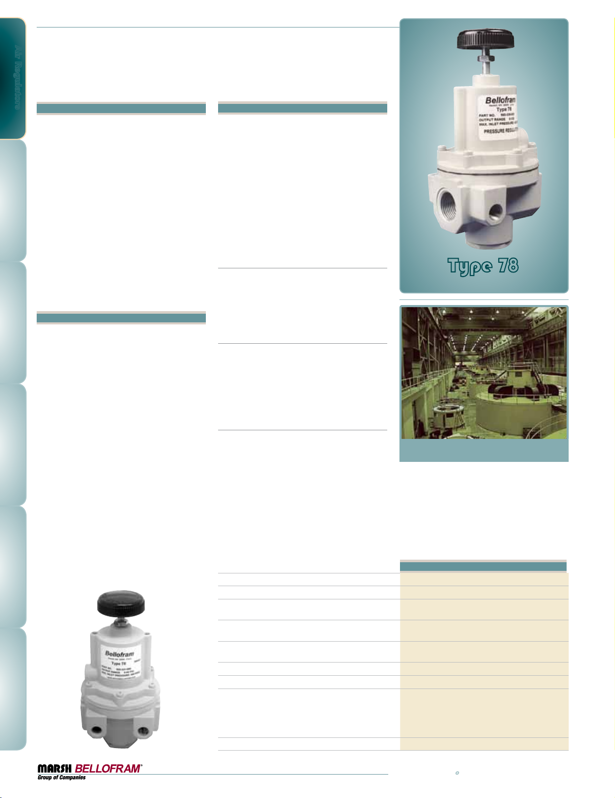
Air Regulators
Type 78
High Flow Air Regulator Series
Features
•Bellofram Rolling Diaphragm Provides
Low-Friction, Long Life Service
•Available in 3/8, 1/2, 3/4, and 1
NPT and BSPT
•Output Gauge Ports are 1/4 NPT
•Options: Low-bleed, Non-relieving, Tamper
Resistant Cover, Square-head Adjustment,
T-handle Adjustment, Epoxy Paint, Tapped
Supply Gauge Port, and Tapped Exhaust
•Mounting Brackets and Repair Kits Available
•Output Ranges are 0-2, 0-10, 0-30, 0-60,
0-125 PSIG 0-0.1, 0-0.7, 0-2.1, 0-4.1, 0-8.6 BAR
•Maximum Supply Pressure is Rated at
400 PSIG / 27.6 BAR
•Flow rates of well over 200 SCFM
Description
The Type 78 regulator is specifically designed
for applications that require large flow capability and accurate pressure control. This regulator
offers low droop, high accuracy, and fine
adjustment sensitivity. The use of a Bellofram
rolling diaphragm provides greater sensitivity
and improved accuracy. The Type 78 offers a
balanced pintle, which minimizes output pressure changes caused by fluctuations in supply
pressure. Careful design and quality materials
throughout assure long, trouble-free operation. The rugged die-cast zinc and aluminum
housings are pressure tested to assure safe
operation, and are designed to withstand harsh
and abusive environments. This durability is
attributed to a chemical conversion coating of
all cast components and a vinyl paint finish.
With a maximum supply pressure of up to 400
PSIG/27.6 BAR and output ranges up to 125
PSIG/8.6 BAR, the Type 78 can achieve flow
rates of well over 200 SCFM. It can be panel or
pipe mounted.
Operation
Marsh Bellofram’s Type 78 is a direct acting,
diaphragm-operated regulator. Once set to a
desired output pressure, this precision regulator
maintains the setting permanently. The range
spring, which has been compressed by the
adjustment knob, causes the pintle to move
downward, opening the supply valve and allowing air flow. The pressure builds up against the
control diaphragm until the supply valve closes.
This is the equilibrium or set pressure, which is
closely maintained under changes in operating
conditions in the following manner:
Downstream Pressure Drop
A drop in downstream pressure reduces the
diaphragm pressure force, upsetting the equilibrium condition. This unbalance causes the
supply valve to open until the pressure builds
up once more to the equilibrium condition.
Downstream Pressure Increase
An increase in downstream pressure acts on
the diaphragm, causing the relief seat in the
diaphragm assembly to lift and open. The
excess pressure is exhausted through the vent
port until the output pressure is restored to the
set point. The relief valve then closes.
Changes in Forward Flow
Under forward flow conditions, the range spring
force is balanced by the diaphragm pressure
force, with the supply valve open just enough
to maintain the required forward flow. When
high flow occurs, a specially designed aspirator helps maintain downstream pressure and
compensates for droop.
Sensitivity
Flow Capacity
Exhaust Capacity
Air Consumption
Effect of Supply Pressure on Regulated Pressure
Supply Pressure Max
Weight
Materials of Construction
Mounting Options
Type 78
Pressure Regulator Series
The Type 78 regulator is specifically
designed for applications that
require large flow capability and
accurate pressure control.
Type 78
Less than 1" water column
See Performance Curves
14 SCFM at 5 PSI / 0.3 BAR above 20 PSIG / 1.4 BAR
set point (0-30 PSIG / 0-2.1 BAR range unit)
less than 12 SCFH at 125 PSIG / 8.6 BAR
output pressure
less than ± 0.35 PSIG / 0.02 BAR for a supply
variation of 100 PSIG / 6.9 BAR
400 PSIG / 27.6 BAR
Approx. 5 lbs.
Body: Die Cast Zinc
Bonnet: Die Cast Aluminum Alloy
Knob: Phenolic Plastic, Plated Steel
Diaphragms: Nitrile Elastomers with Dacron Fabric
Other Internal Materials: Brass, Stainless Steel, and Zinc
Pipe or Panel
30
800.727.5646 • www.marshbellofram.com
Page 31
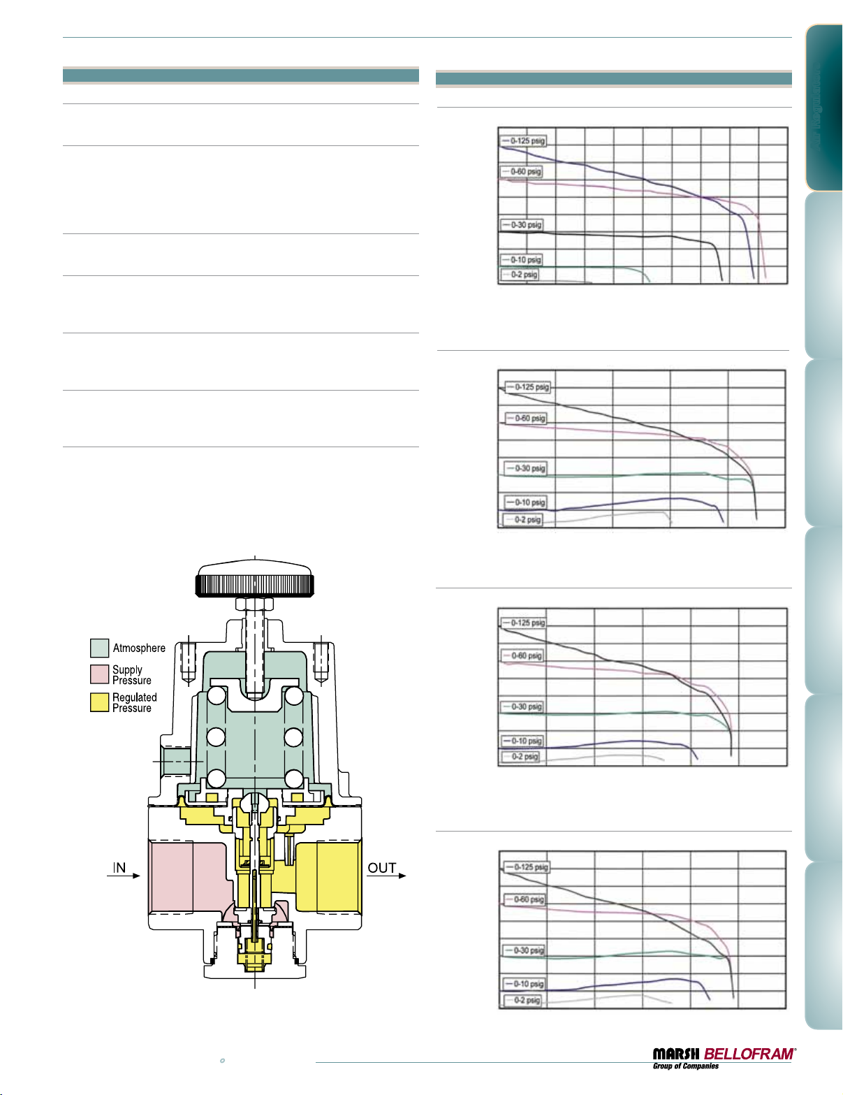
Options
Low Bleed
Reduces steady-state air consumption by approximately 50%.
Non-relieving
Used in applications where it is desirable to relieve pressure downstream
of the regulator, for some constant flow applications and where the gas
flowing through the regulator must not escape at the regulator. Non-relieving regulators should not be used for low or no flow applications.
Handle Options
“T” handle or square head.
Epoxy Paint
A gray epoxy finish applied to the body of the regulator to provide greater
resistance to corrosive environments.
Tapped Vent (Exhaust)
1/4 NPT tapped port to allow for installation of plumbing to capture
exhaust air.
Tapped Supply Gauge Port
1/4 NPT tapped port is offered as a pressure tap for monitoring the inlet
or upstream pressure supplied to the regulator.
Tamper Resistant Cover
An aluminum tubular cover placed over a slotted head adjusting screw
and screwed on the bonnet of the regulator with a wrench, prevents
ordinary hand adjustments.
www.marshbellofram.com • 800.727.5646
Type 78 Typical Performance Curves
Droop Curve 3/8 NPT
PSIG BAR
6.2 90.00
5.5 80.00
4.8 70.00
4.1 60.00
3.4 50.00
2.8 40.00
Regulated PRessuRe
2.1 30.00
1. 4 20.00
0.7 10.00
0.0 0.00
SCFM 0 20 40 60 80 100 120 140 160 180 200
3
m
/HR 0 34 68 102 136 170 204 238 272 306 340
Droop Curve 1/2 NPT
PSIG BAR
6.2 90.00
5.5 80.00
4.8 70.00
4.1 60.00
3.4 50.00
2.8 40.00
Regulated PRessuRe
2.1 30.00
1. 4 20.00
0.7 10.00
0.0 0.00
SCFM 0 50 100 150 200 250
3
m
/HR 0 85 17 0 255 340 425
Droop Curve 3/4 NPT
PSIG BAR
6.2 90.00
5.5 80.00
4.8 70.00
4.1 60.00
3.4 50.00
2.8 40.00
Regulated PRessuRe
2.1 30.00
1. 4 20.00
0.7 10.00
0.0 0.00
SCFM 0 50 100 150 200 250 300
3
m
/HR 0 85 17 0 255 340 425 510
Droop Curve 1 NPT
PSIG BAR
6.2 90.00
5.5 80.00
4.8 70.00
4.1 60.00
3.4 50.00
2.8 40.00
Regulated PRessuRe
2.1 30.00
1. 4 20.00
0.7 10.00
0.0 0.00
SCFM 0 50 100 150 200 250 300
3
m
/HR 0 85 17 0 255 340 425 510
Supply Pressure set to 100 psig (6.9 BAR)
FoRwaRd Flow
Supply Pressure set to 100 psig (6.9 BAR)
FoRwaRd Flow
Supply Pressure set to 100 psig (6.9 BAR)
FoRwaRd Flow
Supply Pressure set to 100 psig (6.9 BAR)
FoRwaRd Flow
Air Regulators
31
Page 32
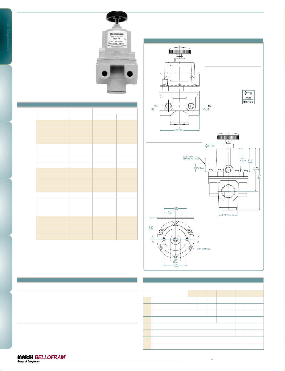
Air Regulators
Type 78 Ordering Information
Part Number
960-326-000 3/8 0-2.1 0-30
960-327-000 1/2 0-2.1 0-30
960-328-000 3/4 0-2.1 0-30
960-329-000 1 0-2.1 0-30
960-330-000 3/8 0-4.1 0-60
960-331-000 1/2 0-4.1 0-60
960-332-000 3/4 0-4.1 0-60
960-333-000 1 0-4.1 0-60
960-334-000 3/8 0-8.6 0-125
T78
960-335-000 1/2 0-8.6 0-125
960-336-000 3/4 0-8.6 0-125
960-337-000 1 0-8.6 0-125
960-346-000 3/8 0-0.1 0-2
960-347-000 1/2 0-0.1 0-2
960-348-000 3/4 0-0.1 0-2
960-349-000 1 0-0.1 0-2
960-350-000 3/8 0-0.7 0-10
960-351-000 1/2 0-0.7 0-10
960-352-000 3/4 0-0.7 0-10
960-353-000 1 0-0.7 0-10
Port Size
(NPT)
Type 78 Dimensional Drawing
Front View
Range*
BAR PSIG
Side View
Top View
BSPT: British Standard Pipe Threads can by ordered
by adding “BSPT” to the end of the part number.
*Although the regulator can be shut off, the recommended operating
ranges are between 10% and 100% of the adjustment range.
Accessories
Gauges
1-1⁄2" gauge kits are recommended for supply and output.
Mounting Brackets
Zinc plated steel bracket to allow for side or panel mounting.
Part #607-293-000
Repair Kit
Includes control diaphragm and pintle assembly. Part #971-157-000
32
Type 78 Option Ordering Matrix
Replace last three digits of part number with digits from table below.
Option
Low Bleed 001 0 31 0 41 0 51 0 61 071 081
1
Non-Relieving 002 032 042 052 062 072 082
2
Sq. head Adj. Screw 003 053 063 073
3
“T” Handle 004 054 064 074
4
Epoxy Finish 005 065 075 085
5
Tapped Vent 006 076 086
6
Tapped Supply Port 007 087
7
Tamper Resistant Cover 008
8
12345678
800.727.5646 • www.marshbellofram.com
Page 33
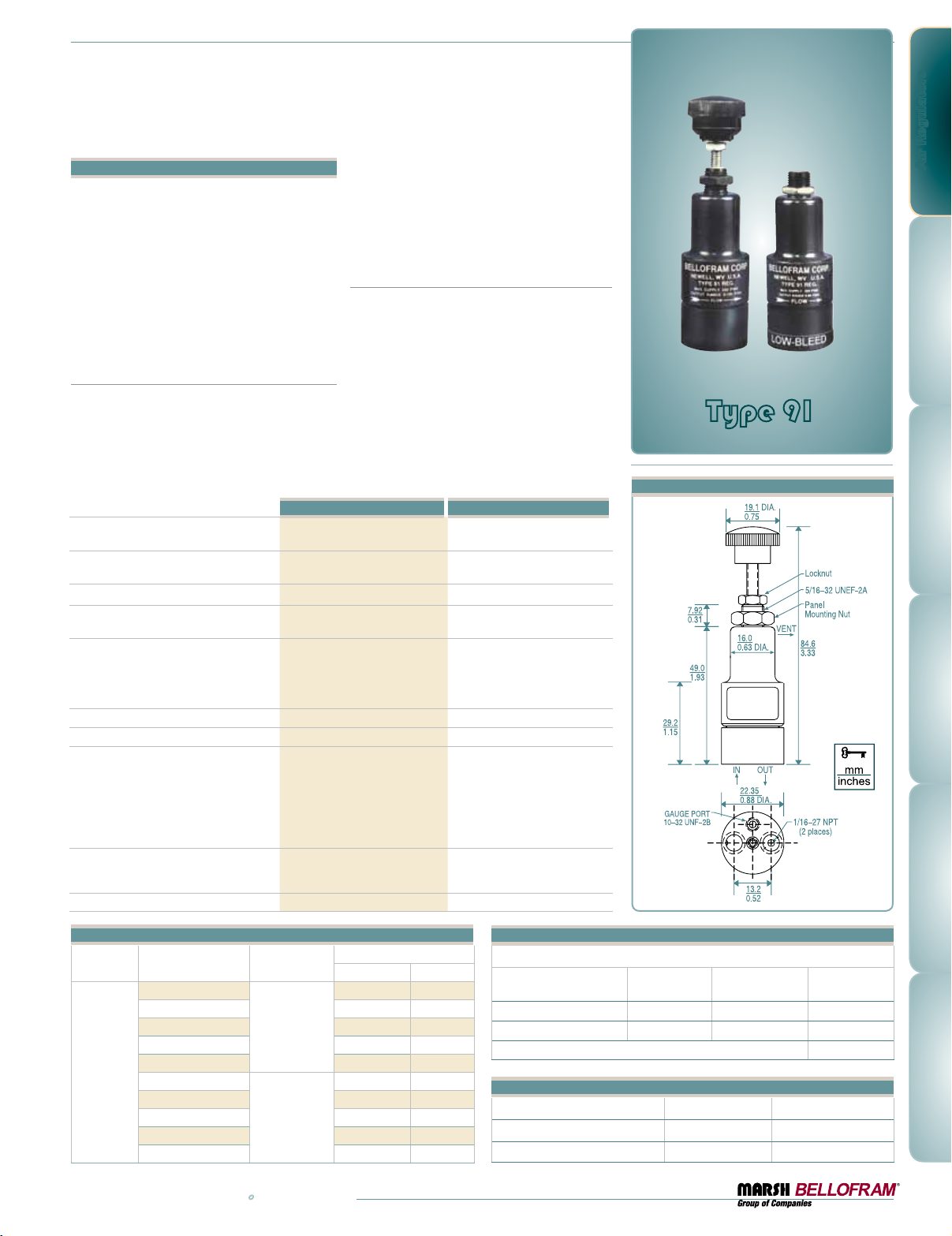
Type 91
Subminiature Regulator Series
Features
•Designed for applications with limited space
and for low flow or dead end service
•Small package size and lightweight construction
•Standard or low bleed versions available
•Corrosion resistant anodized aluminum
exterior
•Excellent stability and repeatability
•Self relieving
•Low cost
Type 91
The Type 91 Subminiature Regulator is a compact, low-cost unit which operates in pressure
ranges up to 100 PSI, with a maximum supply
pressure of 250 PSI. It provides dependable
reliability and accuracy for low flow or dead
end applications, but is not designed for critical
Effect of Supply Pressure Variation
(25 psig) on Outlet Pressure
Exhaust Capacity
(5 psig above 20 psig set point)
Max. Supply Pressure
Flow Capacity at 100 psig (6.9 BAR)
Supply and 20 psig (1.4 BAR) Outlet
Output Pressure Ranges
Total Air Consumption @ Max Output
Port Size
Materials of Construction
Size and Weight
Mounting Options
0.1–0.3 SCFM Typical
250 PSIG (17.2 BAR) 150 PSIG (10.3 BAR)
0-5 PSIG (0-0.35 BAR)
0-15 PSIG (0-1.0 BAR)
0-30 PSIG (0-2.1 BAR)
0-60 PSIG (0-4.1 BAR)
0-100 PSIG (0-6.9 BAR)
Body: Anodized Aluminum
Adjusting Screw: Plated Steel
Diaphragm: Fluorocarbon with
0.875" X 0.875" X 3.33"
(22.2 X 22.2 X 84.6 mm)
flow applications. The Type 91 subminiature
regulator is available with a corrosion resistant
anodized aluminum body and bonnet or with
a brass body and bonnet. Both come standard
with a fluorocarbon diaphragm.
Type 91 Low Bleed
The Type 91 low bleed version is designed for
applications where low air consumption is
required. The Type 91 is ideal for applications
where space is limited and for dead ended/low
flow service. Such applications include ink
control on printing presses, panel loading applications, hand-held analyzers and calibration
equipment, small cylinder operations, and all
types of instrumentation applications. It can be
through panel mounted or, due to its lightweight, pipe mounted. A slotted adjustment
screw is available for precision control.
Type 91 Type 91 Low Bleed
< 0.25 PSIG
(17.02 mBAR)
(2.8-8.5 LPM)
2.5 SCFM (71 LPM) 1.4 SCFM (40 LPM)
3 SCFH (1.42 LPM) 0.3 SCFH (0.14 LPM)
1/16 NPT / 5mm 1/16 NPT / 5mm
Trim: Brass, Acetal
Polyester Fabric
Knob: Acetal Resin
Spring: Music Wire
2.2 oz. (0.06 kg)
Pipe or Panel Pipe or Panel
< 0.5 PSIG
(34.5 mBAR)
0.1–0.3 SCFM Typical
(2.8-8.5 LPM)
0-5 PSIG (0-0.35 BAR)
0-15 PSIG (0-1.0 BAR)
0-30 PSIG (0-2.1 BAR)
0-60 PSIG (0-4.1 BAR)
0-100 PSIG (0-6.9 BAR)
Body: Anodized Aluminum
Adjusting Screw: Plated Steel
Trim: Brass, Acetal
Diaphragm: Fluorocarbon with
Polyester Fabric
Knob: Acetal Resin
Spring: Music Wire
0.875" X 0.875" X 3.33"
(22.2 X 22.2 X 84.6 mm)
2.2 oz. (0.06 kg)
Air Regulators
Type 91
Subminiature Regulator Series
Type 91 Dimensional Drawing
Type 91 and 91 Low Bleed Ordering Information
Part Number
960-240-000
Port Size
(NPT)
Set Point Range
BAR PSIG
0-0.3 0-5
960-236-000 0-1.0 0-15
960-237-000 0-2.1 0-30
1/16
960-238-000 0-4.1 0-60
Type 91
960-239-000 0-6.9 0-100
962-036-000
0-0.3 0-5
962-083-000 0-1.0 0-15
962-033-000 0-2.1 0-30
5mm
962-034-000 0-4.1 0-60
962-035-000 0-6.9 0-100
www.marshbellofram.com • 800.727.5646
Type 91 Option Ordering Matrix
Replace last three digits of part number with digits from table below.
Option Non-Relieving Slotted Adj.
Non Relieving
Slotted Adj. Screw
Low Bleed
002 032 —
Screw
003 103
Low Bleed
010
Type 91 Barbed Fittings
Port Size Part Number
In/Out Port
Gauge Port
1/16 NPT 622-000-007
10 - 32 UNF 622-000-031
33
Page 34
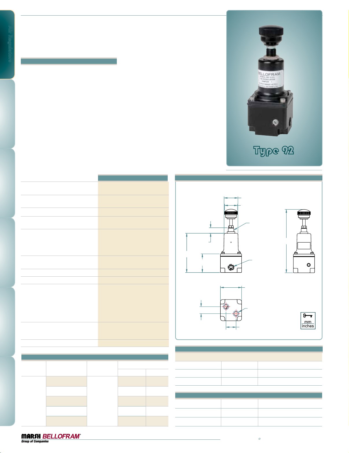
Air Regulators
Type 92
Subminiature Regulator Series
Features
•Designed for applications with limited space
and for low flow or dead end service
•Small package size and lightweight construction
•Corrosion resistant anodized aluminum
exterior
•Excellent stability and repeatability
•Self relieving
•Low cost
With the new Type 92, Marsh Bellofram has
created a subminiature regulator with a true
rolling diaphragm design. Most subminiature
regulators utilize a flat diaphragm, which in this
small of a regulator causes excessive droop and
low stability. By utilizing a larger diameter rolling diaphragm, the Type 92 regulator offers a
more sensitive regulator with excellent stability
and significantly less droop.
The Type 92 Subminiature Regulator is a compact, low-cost unit which operates in pressure
ranges up to 100 PSI, with a maximum supply
pressure of 150 PSI. It provides dependable
reliability and accuracy for low flow or dead
end applications. The Type 92 subminiature
regulator is available with a corrosion resistant
anodized aluminum body and bonnet. Comes
standard with a fluorocarbon diaphragm.
Type 92
Subminiature Regulator Series
Effect of Supply Pressure Variation
(25 PSIG) on Outlet Pressure
Exhaust Capacity
(5 psig above 20 PSIG set point)
Maximum Supply Pressure
Flow Capacity at 100 PSIG (6.9 BAR)
Supply and 20 psig (1.4 BAR) Outlet
Standard Output Pressure Ranges
Total Air Consumption
at Max Output Pressure
Operating Temperature Range
Port Size
Materials of Construction
Size and Weight
Mounting Options
Type 92 Ordering Information
Part Number
Port Size
(NPT)
960-540-000
Type 92
< 0.5 PSIG
(35.5 mBAR)
0.1–0.3 SCFM Typical
(2.8-8.5 LPM)
150 PSIG (10.3 BAR)
5 SCFM (141 LPM)
0-5 PSIG (0-0.35 BAR)
0-15 PSIG (0-1.0 BAR)
0-30 PSIG (0-2.1 BAR)
0-60 PSIG (0-4.1 BAR)
0-100 PSIG (0-6.9 BAR)
0.3 SCFH (0.14 SLPM)
0 - +160˚F ( -18˚- 71˚C)
1/16 NPT - Side and Bottom Ports
Body: Anodized Aluminum
Bonnet: Anodized Aluminum
Trim: Acetal, Brass, Stainless Steel
Diaphragm: Fluorocarbon with Polyester
Fabric
Knob: Acetal Resin
Spring: Stainless Steel, Music Wire
1.19" X 1.19" X 3.55"
(30.2 X 30.2 X 90.2 mm)
2.8 oz. (0.08 kg)
Pipe or Panel
Set Point Range
BAR PSIG
0-0.3 0-5
Type 92 Dimensional Drawing
inches [mm]
.31 [7.92]
2.20 [55.75]
1.05 [26.54]
.39 [9.91]
.775 [19.70]
.72 [18.26]
5/16-32 UNEF-2A
3.55 [90.07]
IN
1/16-27 NPT
1.19 [30.18]
2X 1/16-27 NPT
.560 [14.22]
Type 92 Option Ordering Matrix
Replace last three digits of part number with digits from table below.
Option Non- Relieving Slotted Adj. Screw
Non Relieving 002 032
Slotted Adj. Screw 003
34
Type 92
960-541-000 0-1.0 0-15
960-542-000 0-2.1 0-30
1/16
960-543-000 0-4.1 0-60
960-544-000 0-6.9 0-100
Type 92 Barbed Fittings
Port Size Part Number
In/Out Port 1/16 NPT 622-000-007
Gauge Port 10 - 32 UNF 622-000-031
800.727.5646 • www.marshbellofram.com
Page 35
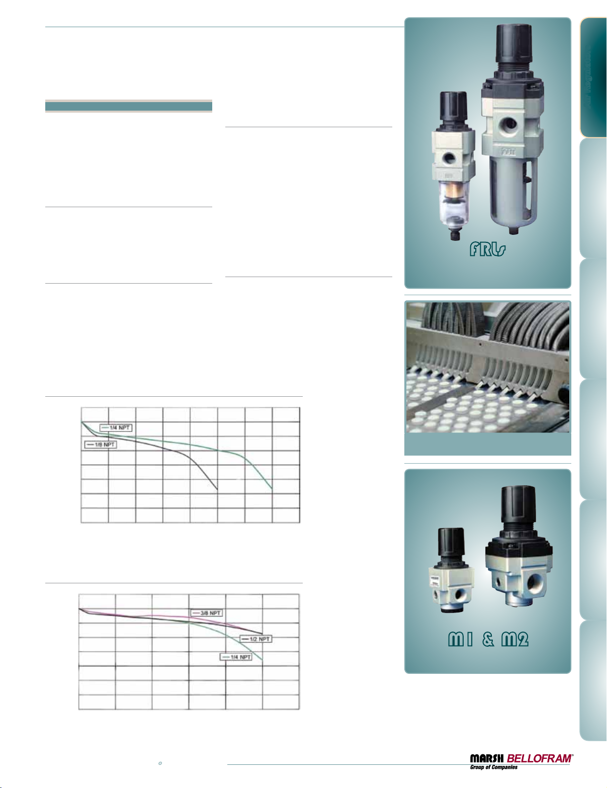
FRLs
Filters, Regulators and Lubricators
Features
•Modular design for service and
interchangeability
•Miniature (M1) and Standard (M2)
•Small package size and light weight
construction
•Competitively priced
Filters
•M1 has polycarbonate bowl
•M2 has polycarbonate bowl with metal guard
•Stock Elements - 5, 25 or 50 micron
•Manual, semi-auto or auto drain available
Regulators
•Bellofram® Rolling Diaphragm for superior
regulator performance
•Panel, pipe, or bracket (included) mounting
•Metal body, polycarbonate bonnet and knob
•Non-rising adjustment knob with push-pull
lock ring feature
M1: Regulated Pressure VS. Flow
PSIG BAR
80 5.5
70 4.8
60 4.1
50 3.4
40 2.8
30 2.1
Regulated PRessuRe
20 1.4
10 0.7
0 0
SCFM 0 10.0 20.0 30.0 40.0 50.0 60.0 70.0 80.0
LPM 0 300 575 850 1150 1400 1700 2000 2265
oRwaRd Flow
F
Filter Regulators
•Aluminum and polycarbonate construction
•Manual, semi-auto or autodrain available
•M1 has polycarbonate bowl;
•M2 have polycarbonate bowl with
metal guard
•Non-rising adjustment knob with push-pull
lock ring feature
•For panel or bracket mounting
•Bellofram
®
Rolling Diaphragm for superior
regulator performance
Lubricators
•M1 has polycarbonate bowl;
remove bowl for filling.
•M2 has polycarbonate bowl with metal
guard; top plug permits filling without
removing bowl or shutting off air
•Adjust drip rate by hand, using graduated
ring on M1, with screwdriver on M2
Air Regulators
FRLs
Filters, Regulator
and Lubricators
M2: Regulated Pressure VS. Flow
PSIG BAR
80 5.5
70 4.8
60 4.1
50 3.4
40 2.8
30 2.1
Regulated PRessuRe
20 1.4
10 0.7
0 0
SCFM 0 10.0 20.0 30.0 40.0 50.0 60.0 70.0 80.0
LPM 0 300 575 850 1150 1400 1700 2000 2265
www.marshbellofram.com • 800.727.5646
oRwaRd Flow
F
M1 & M2
Regulators
35
Page 36
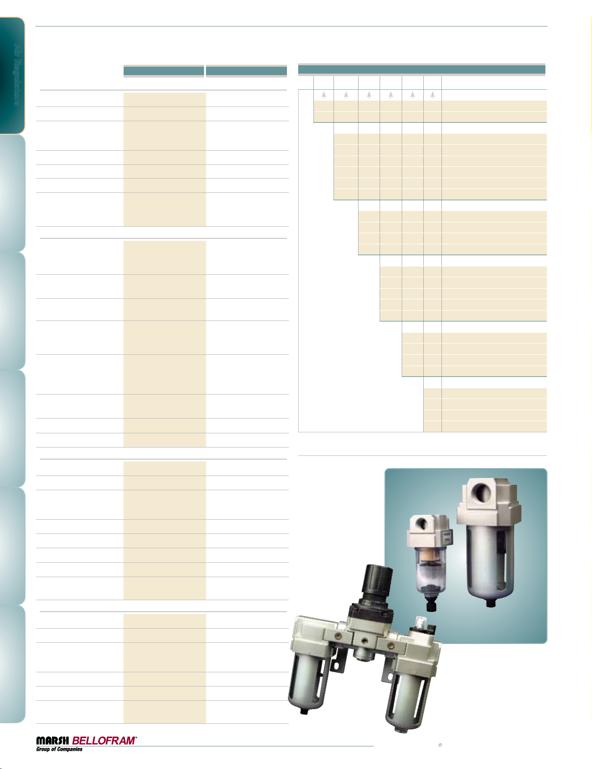
Air Regulators
Filters
Port Size
Filtration (micron)
Maximum Supply Pressure
Temperature Range
Drain
Bowl Capacity
Flow (based on 100 PSI
inlet pressure with 50
micron filter)
Regulators
Effect of Supply Pressure
variation (25 PSIG) on
Outlet Pressure
Exhaust Capacity (5 PSIG
above 20 psig set point)
Maximum Supply Pressure
Flow Capacity at 100 PSIG
(6.9 BAR) supply and 70
PSIG (4.8 BAR) outlet
Output Pressure Ranges
Total Air Consumption
@ Maximum Output
Port Size
Mounting Options
Filter-Regulators
Port Size
Filtration (micron)
Maximum Supply Pressure
Temperature Range
Drain
Bowl Capacity
Regulator Output Range
Flow (based on 100 PSI
supply/70 PSI out)
Lubricators
Port Size
Lubrication
Maximum Supply Pressure
Temperature Range
Bowl Capacity
Flow (based on 100 PSI
inlet pressure)
Type M1 Type M2
1⁄8, 1⁄4 NPT 1⁄4, 3⁄8, 1⁄2 NPT
5µ, 25µ, 50
41–140˚F / 5–60˚C 41–140˚F / 5–60˚C
Manual / Semi-Auto Manual / Semi-Auto / Auto
55, 85 SCFM 120, 120, 120 SCFM
(13.8 mBAR)
<0.25 SCFM
40, 60 SCFM 90, 120, 120 SCFM
0-10 PSIG (0-0.69 BAR)
0-30 PSIG (0-2.1 BAR)
0-60 PSIG (0-4.1 BAR)
0-120 PSIG (0-8.3 BAR)
0.3 SCFH (0.14 LPM) 0.3 SCFH (0.14 LPM)
1⁄8, 1⁄4 NPT 1⁄4, 3⁄8, 1⁄2 NPT
Pipe, Panel or Bracket Pipe, Panel or Bracket
1⁄8, 1⁄4 NPT 1⁄4, 3⁄8, 1⁄2 NPT
5µ, 25µ, 50
41–140˚F / 5–60˚C 41–140˚F / 5–60˚C
Manual / Semi-Auto Manual / Semi-Auto / Auto
0-10, 0-30, 0-60, 0-120 psi 0-10, 0-30, 0-60, 0-120 psi
40, 60 SCFM 90, 120, 120 SCFM
1⁄8, 1⁄4 NPT 1⁄4, 3⁄8, 1⁄2 NPT
41–140˚F / 5–60˚C 41˚–140˚F / 5˚–60˚C
55, 115 SCFM 125, 125, 125 SCFM
µ
1.0 MPa
10 BAR
145 PSI
3
0.75 inch
< 0.2 PSIG
(<7 LPM
145 PSIG
(10 BAR)
0-10 PSIG (0-0.69 BAR)
0-30 PSIG (0-2.1 BAR)
0-60 PSIG (0-4.1 BAR)
0-120 PSIG (0-8.3 BAR)
µ
1.0 MPa
10 BAR
145 PSI
3
0.75 inch
Mist Mist
1.0 MPa
10 BAR
145 PSI
3
1.22 inch
5µ, 25µ, 50
1.0 MPa
10 BAR
145 PSI
3
2.75 inch
< 0.2 PSIG
(13.8 mBAR)
<0.25 SCFM
(<7 LPM)
145 PSIG
(10 BAR)
5µ, 25µ, 50
1.0 MPa
10 BAR
145 PSI
3
2.75 inch
1.0 MPa
10 BAR
145 PSI
3
5.18 inch
µ
µ
FRL Ordering Information
M
Size
1
2
Miniature Series
Standard Series
Description
F
R
L
FR
FRP
FRL
Filter
Regulator
Lubricator
Filter Regulator
Filter Regulator PLUS Lubricator
Filter, Regulator, Lubricator
Port Size
1N
2N
3N
4N
1⁄8 NPT (M1 only)
1⁄4 NPT (M1 or M2)
3⁄8 NPT (M2 only)
1⁄2 NPT (M2 only)
Pressure Ranges
A
L
M
H
—
0-10 PSI, (M1 and M2)
0-30 PSI
0-60 PSI
0-120 PSI, Standard
Omit for Filters and Lubricators
Filters
C
B
F
—
50 Micron Filter, Standard
25 Micron Filter
5 Micron Filter
Omit for Regulators and Lubricators
Drain
Manual Drain, Standard
M
Semi-Automatic Drain
S
Auto Drain (M2 only)
NOTE: Individual regulators, FRs, filters, and lubricators come complete with bracket.
FRL assemblies come complete with all bracket/connectors.
A
Omit for Regulators and Lubricators
—
Filters
36
800.727.5646 • www.marshbellofram.com
 Loading...