

Page 1

INSTALLATION &
OPERATION INSTRUCTIONS
Freestanding Oven
BDFS905X
BDFS905X-F
May 21 v4
Page 2

Page 3
ENVIRONMENTAL WARNING
Waste packaging
Do not throw the packaging of your appliance into the dustbin,
but pick out the different materials (for instance foil, paperboard,
polystyrene) according to the local rules for rubbish elimination.
This appliance must only be used for the purpose of domestic
cooking.
GENERAL INFORMATION
WHEN YOU CALL FOR SERVICE
When you call for service or order parts for your unit, be
sure to give:
1.
MODEL
2.
SERIAL NUMBER
3.
COLOUR
4.
PART NAME and/or description of problem
5. YOUR FULL NAME, ADDRESS, and HOME TELEPHONE
NUMBER and BUSINESS TELEPHONE NUMBER IF
APPROPRIATE.
Servicing shall be carried out only by authorised personnel.
SECTION FOR THE QUALIFIED TECHNICIAN
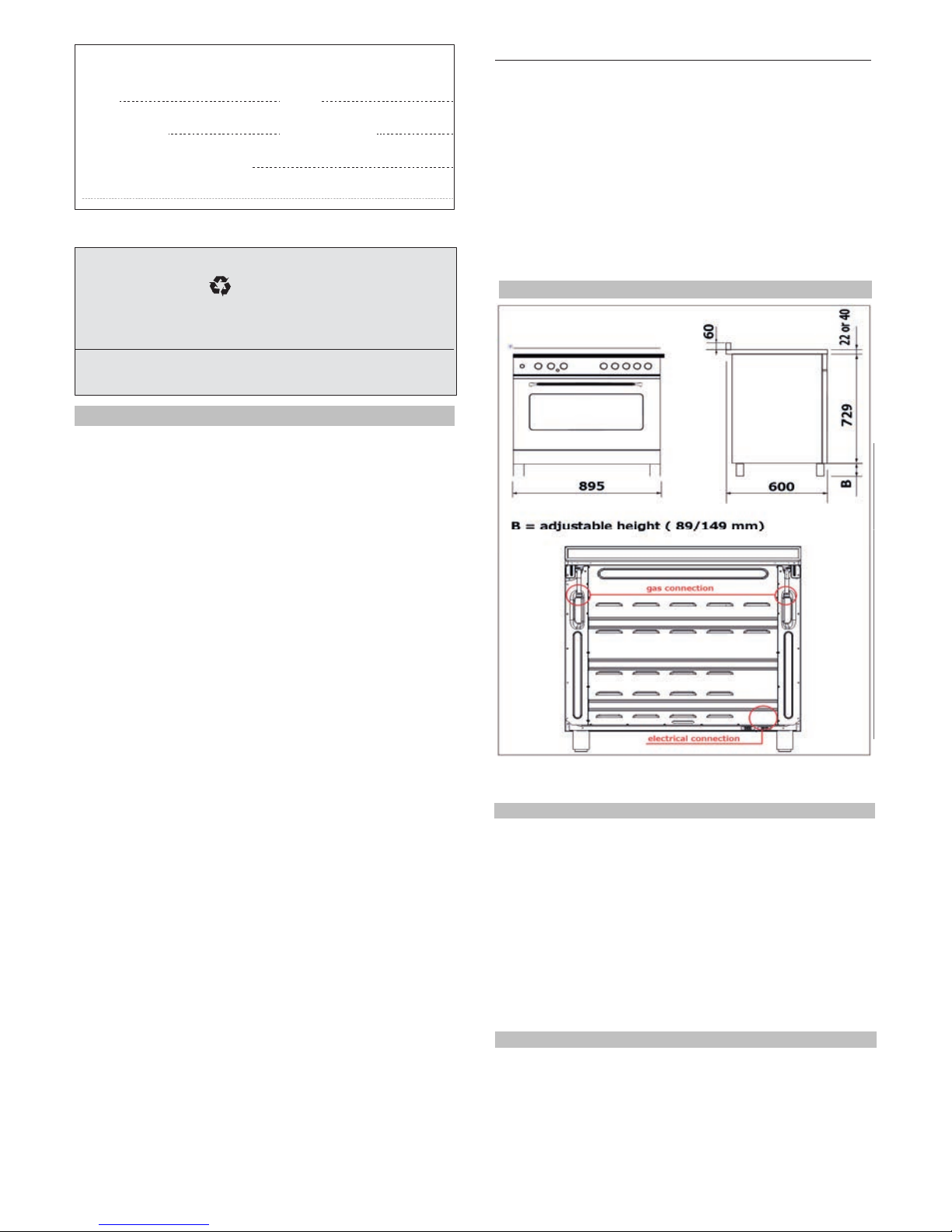
OVERALL DIMENSIONS
Getting to know your new cooker
Thank you for choosing one of our products.
Our cookers are of simple, rational design. They are
constructed to the best standards to ensure good
service and outstanding safety.
Please read this manual carefully; it will provide all the
advice needed to allow you to obtain the best results
from the very first day.
ATTENTION:
- Before using the appliance, do not forget to remove the
plastic protective film from
parts of the appliance.
•
WARNING -Accessible parts will become hot when in use.
To avoid burns and scalds children should be kept away.
- WARNING -
In order to prevent accidental tipping of the appliance, for example
by a child climbing onto the open oven door, the stabilizing means
must be installed.
- WARNING
This appliance is not intended for use by persons (including
children) with reduced physical, sensory or mental capabilities,
or lack of experience and knowledge, unless they have been
given supervision or instruction concerning use of the appliance
by a person responsible for their safety.
Children should be supervised to ensure that they do not play
with the appliance.
Young children and infirm persons should not be left
unsupervised in the vicinity.
- WARNING
Before you use the appliance for the first time, check that the
plastic films protecting some parts (fascia panel, parts in stainless
steel, etc.) have been removed.
- WARNING:
A steam cleaner is not to be used cleaning this appliances.
- WARNING
DO NOT USE OR STORE FLAMMABLE MATERIALS IN
THE APPLIANCE STORAGE DRAWER OR NEAR THIS
APPLIANCE.
DO NOT SPRAY AEROSOLS IN THE VICINITY OF THIS
APPLIANCE WHILE IT IS IN OPERATION.
WHERE THIS APPLIANCE IS INSTALLED IN MARINE
CRAFT OR IN CARAVAN, IT SHALL NOT BE USED AS A
SPACE HEATER
DO NOT MODIFY THIS APPLIANCE.
INS TALL ATION
PROVISION FOR VENTILATION
The room where the Cooker is installed should have permanent
ventilation as follows:
"Ventilation must be in accordance with AS5601/AG 601 - Gas
Installations. In general, the appliance should have adequate
ventilation for complete combustion of gas, proper flueing and to
maintain temperature of immediate surroundings within safe limits."
Do not install in a bed-sitting room, a bathroom or shower room.
If there is another fuel burning appliance in the same room, a
higher level of ventilation will be required, you should consult
-
" the safety requirements".
In addition to the above, during prolonged use, opening a window
in the same room is recommended. This will avoid the build up
of excessive moisture and condensation.
POSITIONING
Important: Fix the chain located next to the gas connection on
both sides of the cooker to the wall to prevent the cooker from
tilting. Both chains must be securely fixed.
Make sure that the wall surface behind the Cooker is noncombustable (will not catch fire).
Where a painted surface is adjacent, a fire retardent paint surface
is recommended. Wallpaper, wood, or fabric should not be used
behind or next to the cooker.
RECORD HERE FOR EASY REFERENCE
Model Colour
Serial
Number Installation Date
Dealer's Name and Address
% $GMXVWDEOH KHLJK
W
UHJ
PP
%
-2-
Page 4
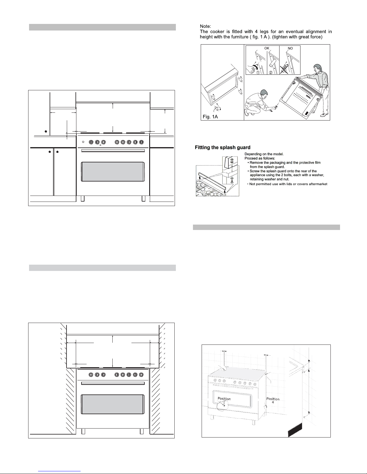
min.100 mm "0" mm "0" mm
min "60" mm min "60" mm "0" mm "0" mm
Fig. A
Clearances to combustible materials
"Any adjoining wall surface (side or rear) situated within 200mm
of any hob burner must be a suitable non-combustible material
from the edge for a height of 150mm for the entire length
of the cooker.
Any combustible construction above the cooker must be at least
650mm above the maintop." Ensure that a power and gas supply
are nearby. The Cooker should be located carefully so that the
heat produced by it has plenty of space to escape. The diagram
below shows an ideal configuration.
WARNING: This appliance is not suitable to be installed on
a base
No part of any adjoining wall surface can be made of combustible
materials. The protection of combustible materials
required by Clause 5.12.1.1 of AS5601-2004 is the fixing of 5 mm
thick ceramic tiles to the surface or attaching fire resistant
material to the surface and covering with sheet metal with a minimum
thickness of 0.4 mm.
"If the cooker is being fitted next to cupboards or adjoing wall
surfaces, which are within 200mm from the edge of the hob
burner and of a suitable non-combustible material as specified
in AS5601, then ensure that a distance of at least 6cm is left
between the edge of the cooker and the non-combustible
material. This gap is to allow plenty of space for the heat
produced by the cooker to escape on each side of the cooker.
TO FIX THE COOKER TO THE REAR WALL
WARNING - For safety reasons and to prevent tipping of the appliance,
these stabilizing means must be installed.
The cooker is equipped with 2 chains fixed on each side at the rear of
the cooker near the top (see Fig. A). The chains are fitted with "spring
clips" which must be clipped to the "screw eyes".
Install the "screw eyes" as follows :
1.
Drill four 6mm holes (po siti on 1 - 2 - 3 - 4) in the wal l
as in Fig. A.
2.
Insert part "R" into the holes then screw in the "screw eyes" part
"G"
see Fig. B.
Note: If the part provided is not suitable for the wall material please
use an appropriate device to ensure secure holding of the "screw
eyes" to the wall.
3.
Bring the cook er ne ar the w al l a nd cl ip the c hains on the
"screw eyes" as in Fig. C.
IM P OR TAN T : If t h e co o k er is moved f o r a ny r eas o n
(e.g. maintenance) resulting in the cooker being unclipped from the
wall, the cooker must be re-clipped to the wall at the completion of
the task.
Clearances
to
non-
combustible
materials
min.10
mm
min.
650
mm
min.
400
mm
non-
combustible
materials
min.
650
mm
non-
combustible
materials
chain
550 mm 76 mm
WARNING:
This appliance is not suitable to be installed on a base.
-3-
Page 5
GAS CONNECTION
Gas installation must be made in accordance with AS5601;
Also refer to rangehood manufacturers recommendation.
Check gas presure, note the correct setting from the data
plate sealed inside the front appliance drawer *.
Installing the gas cooker :
(Flexible connection are NOT permitted with this
appliance)
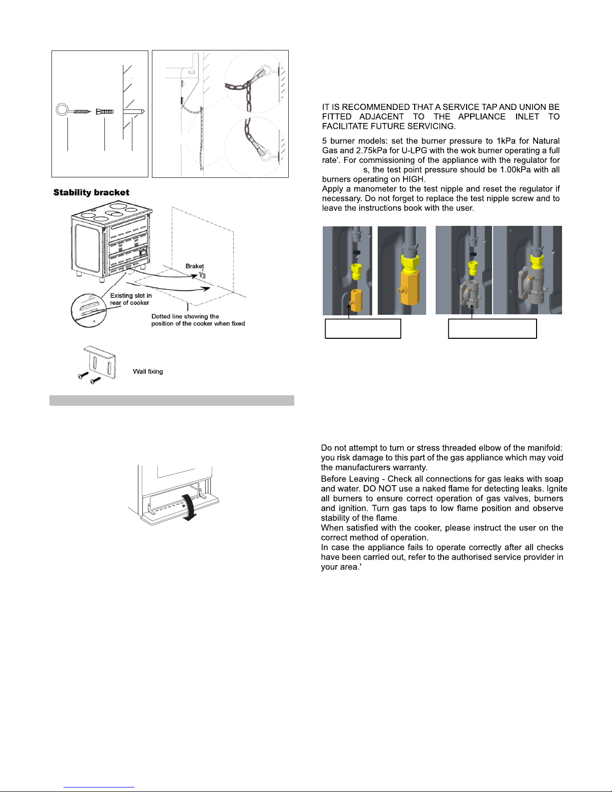
- An inlet manifold extension pipe must be fitted to the
appliance. Part supplied in the drawer of the appliance.
- Ensure that the pipe is connetted using the washer
provided and that the braket is screwed to the appliance
as shown in the diagram below.
- Fit the supplied pressure regulator ( for Natural gas )
using the NG test piont adaptor and washer to the inlet
manifold. Ensure the arrow is pointing towards the
appliance and that pressure testpoint is accessible from
the final position.
- Push the cooker back and install the stabilizing chains.
- Connect the appliance inlet manifold to the consumer
piping outlet using only fixed piping. This final connection
is made when the product is pushed back into position by
access under the cooker.
GAS CONVERSION AND ADJUSTMENT
When used with natural gas all burners have been preset at our
factory and further adjustment should not be necessary. Conversion
kits to other gases are available from the place of purchase. Do
not attempt to fit the conversion kit yourself. Conversion to U-LPG
gas should only be carried out by an authorized technician.
GAS ADJUSTEMENTS
- change the injectors
- adjust the minimum flow
'When converting from Natural Gas to U-LPG ensure that
the NG regulator is removed and replaced with the Test Point
Assembly. A gas regulator suitable for a supply pressure of 2.75kPa
should be part of the gas tank supply and should be adjusted with
the wok burner operating at maximum.
REPLACEMENT OF THE INJECTORS
When required to operate on other gas replace the injectors in
accordance with information referred to in chart below.
Fig. B
wal
G R Hole
Fig. C
wall
G
VERY IMPORTANT FOR THE INSTALLER
The hose assembly
- must comply whit ASINZS 1869 Class B or D,
- be of appropriate internal diameter and be kept
as short as possible ( less than 1,2 mm)
- It must not be kinked
- It must not be in contact whit hot surfaces
Pressure test point
for ULPG
Pressure regulator for
natural gas
A test point fitting must be installed between the piping and
the appliance for the pressure to be checked to ensure it is
operating for ULPG at 2.75 kPa, for NATURAL GAS at 1 kPa.
Be aware that the appliance has two gas inlets (L/R). Before
performing the leakage test select which side will be the
connection point and cap and pressure test the side that will
not be used.
-4-
Page 6
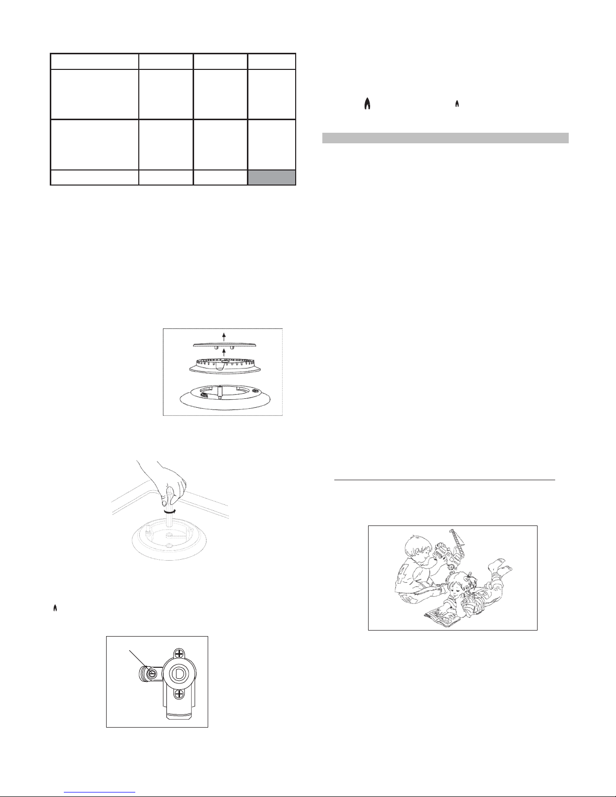
- change the injector (see Fig. D) and replace it with another one
suitable for the new type of gas (see Tab. 1)
WARNING:
2nd SECTION FOR THE USER
Fig. D
MINIMUM FLOW ADJUSTMENT FOR HOB-TOP TAPS
In order to adjust the minimum flame setting proceed as follows:
switch the burner on, and set the knob at the minimum position
. . Remove the knob from the tap,
The minimum adjusting screw «Z» is on the body of the gas tap
(Fig. 2).
Unscrew the adjusting screw in order to increase the flow or screw
it to decrease the flow.
The correct adjustment is obtained when the flame has a length
of about 3 or 4 mm.
For butane/propane gas, the adjusting screw must be screwed
in thigt.
Make sure that the flame does not go out turning quickly from the
max. flow to the minimum flow .
Refit the knob again.
Children should be kept away while the oven or grill is in use
since accessible parts become hot.
- WARNING -
During use, the appliance becomes hot.
Care should be taken to avoid touching heating elements inside
the oven.
- Do not use oven base panel as a shelf, make use of the oven
shelves.
- To avoid splattering and smoke, position collecting tray under
the grill with some water in it.
- Always turn pan handles to the side or to the back of the hob.
If they are left out into the room they can easily be hit or reached
by children, this knocking the pan off the hob.
ELECTRICAL CONNECTION
The appliance must be installed by a suitably qualified person in
accordance with these instructions and with the requirements of
the Australian Wiring Rules AS/NZS 3000.
Fixed wired installations are to be provided with suitable isolation
means in accordance with the said rules.
Any plug socket installed for the purpose of connecting the appliance
to supply must be readily accessible when the appliance is installed.
Before making the connection, make sure that:
1)
the safety circuit-breaker and the electrical system are able to
withstand the load of the appliance (see nameplate).
2)
the power supply system has an earth connection in good
working order in accordance with the regulations in force;
IMPORTANT
The wires in the mains lead are coloured in accordance with the
following code:
GREEN & YELLOW.........................................................EARTH
BLUE ...........................................................................NEUTRAL
BROWN ...............................................................................LIVE
Electric power ..1,5 mm2 3 core cable (15 amp. Fuse required).
Should conform to local authority requirements.
Also refer to rangehood manufacturers recommendations.
This appliance is supplied with a plug & cord, simply plug into a
3 pin household socket outlet witch is properly earthed.
If the supply cord is damaged, it must be replaced by an autherised
service agent.
WARNING: THIS APPLIANCE MUST BE EARTHED.
The flexible mains lead and plug must not be in contact with hot
surfaces.
Z
Fig. 2
- remove the grids
- remove burners
and flame-spreaders.
Tab. 1
Gas Type
kPa Jet mm 0
Bur ners Power MJ/h
Natural
1.00
1.20
Sem ir apid
7.1
0.90
Aux iliary
4.0
1.50
Rapid
11.0
1.63
Triple Crown
12.7
U-LPG 2.75
0.73
Sem ir apid
7.1
0.53
Aux iliary
3.7
0.95
Rapid
11.7
1.00
Triple Crown
13.0
Regulator
NG Regulator
LP Test point
adaptor
Adjustments, conversions and gas installations must only be carried
out by an authorised person.
After the replacement of the injectors , replace also the
label of the type of gas
SPECIAL NOTE
After installation or any servicing operation, always ensure that
the appliance is gas sound and that the components are now
operating correctly. Items removed during servicing should be
replaced in the reverse order to their removal.
In order to change the work-top injectors, it is necessary to act as
follows:
-5-
Page 7
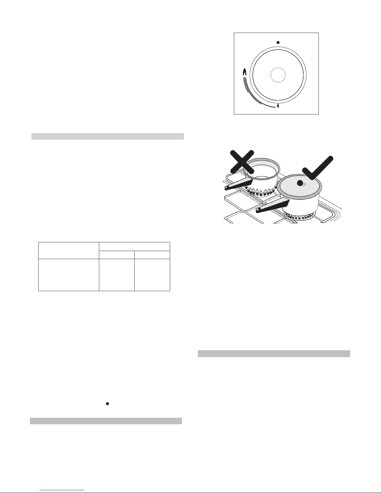
Always use pans with a flat base diameter, which are well balanced
and stable in use, a pan which overhangs the hotplate should not
be used. Avoid using old, misshapen pans, or pans which are
unstable when placed on a flat surface. Do not use "split pans"
as they are inherently unstable.
To save gas, always position pans centrally over the burners and
adjust the flames so that they do not lick up the sides of the pan
and only the base is heated. Always put lids on saucepans and
boil only the amount of liquid you use. When the liquid has boiled
adjust the setting to maintain a simmer. Do not light the burner
until the pan is in position and turn off the burner before removing
the pan. In hard water areas, descale kettles regularly. For safety,
keep saucepan handles turned to a safe position so they are out
of reach of small children and cannot be accidentally knocked.
To tunr the burner OFF, turn the control knob clockwise to the
OFF setting (marked with a dot )
Automatic electric ignition
To turn on a burner, press the knob corresponding to the
selected burner and turn it anticlockwise to the maximum
position. Keeping the knob pressed, the electric automatic
ignition of the burner will be started up. In case there is
not electric current, the burner can also be lighted using a
match.
The small flame indicates the 'low position'.
Turn the knob to it after the contents of a pan have boiled.
The smaller burners are for smaller pans and simmering. Make
sure flames are under the pans. Using a lid will help the contents
boil more quickly.
WARNING
It is not recommended to press push button for ignition if all the
burners are not located in the proper positions. The burner heads,
burner skirts and pan supports are removable for better cleaning:
Always ensure that the burner skirts and heads are replaced
correctly so that the burners function safely and correctly.
During the use of the appliance pay attention that water or any
liquid does not enter into the appliance through the holes of the
burners or around the rods of the valves or the push button
electronic lighter.
Water or juice will produce dangerous short-circuits and can
seriously damage the working of the Hotplate.
HOW TO USE YOUR ELECTRIC OVEN
-
Before cooking in the first time we reccommend that the oven
should be operated at 200° C for 30 minutes to remove any
manufacturing greases and odours.
-
Do not place items or pan directly on to the oven botton.
-
Foil should only be used to cover food and not oven shelves or
party of the oven. When used improperly will obstruct the air
circulation causing problems in cooking and/or harmful accidents.
MULTIFUNCTIONAL OVEN
The oven is fitted with:
•
a lower heating element;
•
an upper heating element;
•
two circular heating element surrounding the fan.
N.B.: Always set the temperature on the thermostat knob before
selecting any of the functions.
Gas and Electricity on
Make sure that the gas supply is turned on and that the appliance
is plugged in and switched on. The ignitor needs electricity.
In case there is no electric current, the burner can also be lighted
using a match.
It is recommended that pans suitable to the size of the burner
should be used as follows:
BURNERS PANS
fl min.
fl max
AUXILIARY
80 mm
160 mm
SEMI-RAPID
120 mm
200 mm
RAPID
200 mm
230 mm
TRIPLE CROWN
230 mm
260 mm
WARNING
*
This appliance is not intended for use by young children or
infirm persons without supervision.
*
Young children should be supervised to ensure that they do
not play with the appliance.
- WARNING -
In order to prevent accidental tipping of the appliance, for example
by a child climbing onto the open oven door, the stabilizing means
must be installed.
Be safe
Please read the rest of the instruction book which contains
important information to help you use the appliance safely and
efficiently.
- 1 Minute
Tour -
- Don't let children sit down or play with the oven door. Do not
use the drop down door as a stool to reach above cabinets.
- Once your cooking is over make sure to close the main gas
supply.
-6-
Page 8
Fan Oven
GE NER AL
IN STRU C TIO N
Oven commutator knob
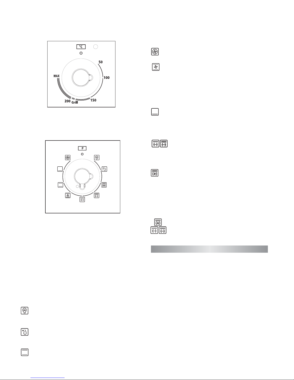
Depending on the type of oven, it is possible to select one of the
following functions turning the commutator knob clockwise.
Use of the oven
Note: ovens with separate thermostat and commutator.
When the functions Grill and Fan Grill are used, place the
thermostat
knob between 180 + 200°C as maximum temperature.
ATTENTION:
The temperature shown on the control panel corresponds to the
temperature in the oven centre only when the functions selected
are Bake or Fan Oven.
Light
When you turn the control knob to this position, the light
will be on for all the following operations.
Defrost
The air at ambient temperature is distributed inside the oven
for defrosting food very quickly and without proteins adulterations.
Note:
All the functions mentioned above switch the oven internal light on.
A warning light on the control panel will stay lit until the temperature
is reached; after it will light up intermittently.
Always use the oven with the oven door closed.
Warning: remember ovens get hot; some parts naturally become
very hot, notably the glass oven door and the protective strip.
Keep children away from oven at all times and warn them about
the danger.
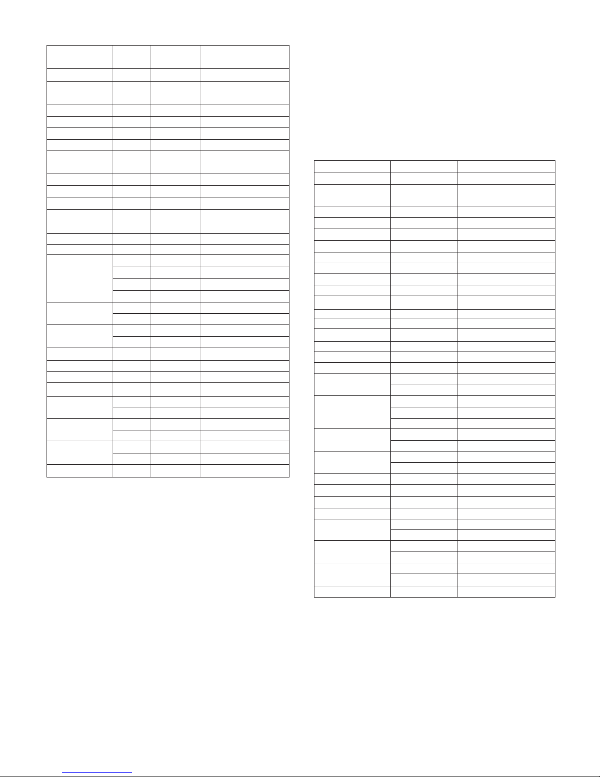
GUIDE FOR CONVENTIONAL COOKING (Bake)
(Outer ring of upper electric element and lower electric element
ON) The following Cooking Guides give the recommended shelf
positions (counted from the bottom), thermostat settings and
approximate cooking times for a range of baked items, using the
Lower
Bake
Fan Bake
Grill
Medium Grill
Fan Grill
Defrost
Light
Co
Pr
sealinng r ed me atss , roast beef
(papillotes), flaaky pastry. Mid sheld possition
nventional c
reheat the o v
ooking : top and bottom heating elements
en for abou,,t ten minutes.
leg of l amb gam e, bread,
This meth od is ideal foor all traditional
food
wrapped
are used together.
roasting a
For
and baking.
foil-
Fa
at a time)
n assiste d m ultilevel oveen:
).
foods pl aced on different
(up to 2 levels
shelves
F
circulates the air inside th
time in one or more positions. This func
ten minuttes
an cooking: both top and bottom heating elements are
times are reduced. Differentt foods can
tion providess even heat
e oven.
penetrates the
food better and both the cooking and preheating
bbe cooked at the same
for poultry , pastries, fish
and the fan
used
and
vegetablees. Heat
Allow a
mix
not
distrebution
and
does
the
smells .
bout
extra when cooking foods at the same time.
Loower element:
disshes.
quicches, tarts, p
radiation from below.
Grill: Caut i
from 50 °
k
n
o
b
m
u
s
t
b
e
s
e
t
C
using the
pa
âté and any
ion: In this f
C to Grill position
.
lower eleme
astry without
y cooking tha
function th e
nt. Ideal for c
over cookin
t needs mo
e temperatur
ooking
g the fruit fill
re heat and
re control
ing. Use this for flans,
Using the
Cooking of simmilar
or
differrent
all pastry based
This allowws you to coook dry tart
top level element. Five minutes preheating is required to get the
element hot. Use the grill when the door is closed.
Fa
control knob mu
necessar
be grilled directly on the shelf
is not too close
n assisted g
ust be set fr
piec
y for red mea
centrally, at
drip tray un
to the grill. T
rilling: Caut
om 50 °C
es of meat
ats but not fo
the middle le
der the shelf
urn the foo d
ion:In this function the temperature
the air inside the oven. Ideal for co
such as roa s
or white mea
evel. Slide the
to collect the
d over halfwa
st pork, poul t
ats. Place the
juices. Mak
ay through co
o
try, e tc. Pre h
food to
e sure that t
ooking.
oking thicke food
stuffs, whole
eating is
the food
to Grill position. The
top heating element iss used in conjunction with the fan circulating
Rotisserie(in option):
in conjunction with the rottisserie proviiding the real flavour
the ttop heating eelement is us ed
of a traditional roast.
conventional oven, using one tray only. Cooking results are a
matter of personal preference and may easily be adjusted to suit
individual requirements by slight adjustment of the temperature
and or cooking time. Preheating of the oven is recommended for
10-15 minutes or until the oven thermostat indicator light
switches off to show the selected temperature has been reached.
When using a baking tray it should be placed centrally on the
oven shelf with the short sides of the tray parallel to the sides
of the oven. Do not use trays, tins or dishes larger than 380 mm
(15") long, 356 mm (14") wide, as cooking results may be
impaired.
recommended.
Recommended
Oven thermostat knob
To obtain an oven temperature between 50°C and MAX°C, turn the
knob clockwise.
-7-
Page 9
Food
Thermostat
setting °C
Shelf Position
(Counted from Bottom)
Cooking Time
Small cakes (12 on tray) 195 3 20 - 30 mins.
Victoria sand wich
(2x7"/1 8 0mm)
190
3
25 - 35 mins.
Swiss roll or whisked sponge 200
3
20 - 25 mins.
Fruit cake ( 8 "/205mm) 155
2
2 - 3 hours.
Sc one s
260
3
10 - 20 mins.
Mering u es
95 2
2 - 3 hours.
Shortcrust Pastry
210
3
25 - 45 mins. dep e nding
Puff or Fl aky Pastry
220
2
20 - 35 mins. upo n
Choux Pastry
220 3 25 - 35 mins. dish
Bis cuits
200/ 220
3
15 - 25 mins.
depending upon type
Br ead
250
2
30 - 40 mins.
Milk pudding
Pi zza
165
270
2
3
1 H - 2 hours.
25 mins.
Lasagne
170
3
75 mins.
Oven noodles
160
3
75 mins.
BE EF on bo ne & crusty
(rare)
(medium)
(well done)
270 rare
3 12 mins. per 1/b (500 g) plus 12 mins.
220 °C
3
15 mins. per 1/b (500 g) plus 15 mins.
220 °C
3
20 mins. per 1/b (500 g) plus 20 mins.
1 8 0 °C
3
25 mins. per 1/b (500 g) plus 15 mins.
LAMB on bone
220 °C
3
20 mins. per 1/b (500 g) plus 20 mins.
170 °C
3
27 mins. per 1/b (500 g) plus 27 mins.
Boned and r olled
220 °C 3 25 mins. per 1/b (500 g) plus 25 mins.
170 °C
3
35 mins. per 1/b (500 g) plus 20 mins.
PORK on bone 220 °C 3 25 mins. per 1/b (500 g) plus 25 mins.
Boned and r oller
1 8 0 °C
3
30-35 mins. per 1/b (500 g) plus 35 mins.
VEAL on bone
220 °C
3
25 mins. per 1/b (500 g) plus 25 mins.
Boned and r oller
220 °C 3 30 mins. per 1/b (500 g) plus 30 mins.
CH ICKE N
220 °C
3
20 mins. per 1/b (500 g) plus 20 mins.
170 °C
3
25 mins. per 1/b (500 g) plus 25 mins.
TU R KEY
220 °C
3
20 mins. per 1/b (500 g)
170 °C
3
25 mins. per 1/b (500 g)
DU C K 220 °C
3
20 mins. per 1/b (500 g)
170 °C
3
25 mins. per 1/b (500 g)
GOOS E 220 °C 3 20 mins. per 1/b (500 g) plus 20
PLATE WARMING
Ovenproof plates and dishes may be warmed in the oven on a
low temperature setting. Remember do not place items directly
into the oven base.
Warning: do not use foil to cover the oven shelves, or any part
of the oven interior including the oven base. Foil should only be
used to cover food and cooking dishes. Always place items which
may boil over (e.g. fruit pies) on a baking tray to prevent spillage
burning onto the oven base. Foil used improperly is frequent
cause of oven problems and painful accidents. Avoid letting grease
deposit collect around the upper heating element: it will cause
smoking and may start a fire.
Remember do not place pan or items directly onto the oven base.
Never leave unit unattended at hight heat settings. Boil over
causes smokingand greasy spill over that may start a fire.
If a grease fire should occur in a pan put out the flame by placing
a lid on the pan. Do not throw water on a grease fire.
GUIDE FOR FORCED CONVECTION COOKING
(Back rolled electric element with fan)
The accessories provided with the oven can be slotted in at 5
positions: the following guide concerns cooking times and
thermostat settings using N. 2 shelves on the same time (in
position N. 2 and N. 4). Cooked results are a matter of personal
preference and may easily be adjusted to suit individual
requirements by slight adjustment of the temperature and/or
cooking time, or when using more or less shelves in the same
time. Preheating of the oven is recommended for 10-15
minutes or until the oven thermostat indicator light switches off
to show the selected temperature has been reached.
When using a baking tray it should be placed centrally on the oven
shelf with the short sides of the tray parallel to the sides of the
oven. Do not use trays, tins or dishes larger than 380mm (15")
long, 356 mm (14") wide, as cooking results may be impaired.
Food
Thermostat setting °C Cooking Time
Small cakes (12 on tray)
175
15-25 mins.
Victoria sandwich
(2x7"/1 8 0mm)
170
20-30 mins.
Swiss roll or whisked sponge
1 8 0
15-20 mins.
Fruit cake ( 8 "/205mm)
135
1 H - 2 H hours.
Scones 210
8 -15 mins.
Meringues
8 0
1 H - 2 H hours.
Shortcrust Pastry
190
20-40 mins. depending
Puff or Flaky Pastry
200
15-30 mins. upon
Choux Pastry
200
20-30 mins. dish
Biscuits
170/1 8 0
10-20 mins. depending upon type
Bread
200/220
25-35 mins.
Milk pudding
150 1 H - 2 hours.
Pizza
250
20 mins.
Lasagne 165
60 mins.
Oven noodles
150
60 mins.
BEEF on bone
230 rare & crusty 9 mins. per 1/b (500 g) plus 9 mins.
BEEF on bone
190 °C (rare)
15 mins. per 1/b (500 g) plus 8 mins.
190 °C (medium) 20 mins. per 1/b (500 g) plus 10 mins.
160 °C (well done) 25 mins. per 1/b (500 g) plus 8 mins.
Boned and rolled 190 °C (rare)
20 mins. per 1/b (500 g) plus 10 mins.
190 °C (medium) 25 mins. per 1/b (500 g) plus 15 mins.
160 °C (well done) 30 mins. per 1/b (500 g) plus 8 mins.
LAMB on bone 190 °C
20 mins. per 1/b (500 g) plus 10 mins.
155 °C
27 mins. per 1/b (500 g) plus 14 mins.
Boned and rolled
190 °C
25 mins. per 1/b (500 g) plus 14 mins.
155 °C
25 mins. per 1/b (500 g) plus 14 mins.
PORK on bone
200 °C
25 mins. per 1/b (500 g) plus 14 mins.
Boned and roller 160 °C
30-35 mins. per 1/b (500 g) plus 1 8 mins.
VEAL on bone
200 °C
25 mins. per 1/b (500 g) plus 14 mins.
Boned and roller
200 °C
30 mins. per 1/b (500 g) plus 14 mins.
CHICKEN
200 °C
20 mins. per 1/b (500 g) plus 10 mins.
155 °C
25 mins. per 1/b (500 g) plus 13 mins.
TURKEY
200 °C
1 8 mins. per 1/b (500 g) plus 14 mins.
155 °C
23 mins. per 1/b (500 g)
DUCK
200 °C
1 8 mins. per 1/b (500 g)
155 °C
23 mins. per 1/b (500 g)
GOOSE
1 8 0 °C
1 8 mins. per 1/b (500 g) plus 20 mins.
USlNG THE GRILL
The grill is situated in the top of the oven compartment.
The grill pan should be located on the top oven shelf position.
Always grill with the door closed.
Warning:
Do not place fatty foods too close to the grill and never leave the
grill unattended. If fatty foods are grilled, or roasting has been
cooked in the oven at a high temperature the grill element may
smoke. This is not dangerous and the smoke is caused by the fat
burning off when the grill element is hot. Leave the grill element
on until the smoking has stopped t-hen use as normal. If a grease
fire should occur in a pan put out the flame by placing a lid on the
pan. Do not throw water on a grease fire.
-8-
Page 10
INSTRUCTIONS
FOR USE OF CONTROL
DEVICES
(Depending on model)
Using the prograammer of ccooking
Main functions (for some models)
1,Time function, keep the time in 24 hours.
2,Make an reservation for the oven work
time, and can set anytime in 24 hours.
3,Set the oven work time, the longest maybe 10 hours.
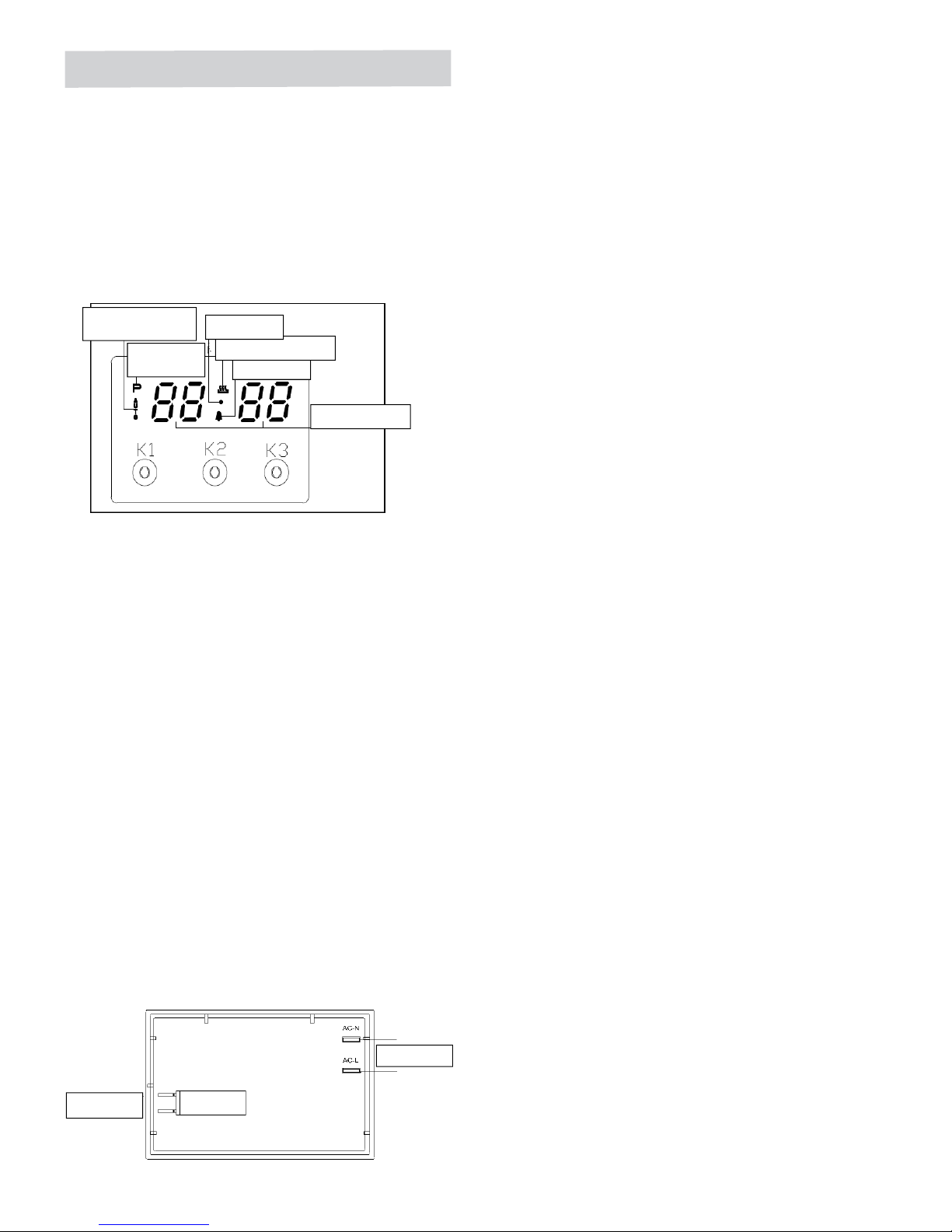
Operation Panel and Instructions (for some models)
1 List of functions
Instructions from left to right: Key1, Key2, Key3.
Key1 Decrease Key
Key2 Mode Key
Key3 Increase Key
Note: Press Key 1 and Key 3 under the setting mode, which
changes the time by one minute either up or down. If keep
pressing them, the number will be up or down quickly.
2 Icon Instructions
“ "Auto-programming icon" : it will flash when
setting automatic
program a nd th e e nd o f automatic program. If automatic program
has been set, after 5s, it will k eep lighting up. At the end of
automatic program, the flash will be off when resetting the clock
or it will keep lighting up when resetting automatic program after 5s.
“"Time-setting Icon" will flash when setting time.
“ "Sec Icon" and "Alarm Icon"” are flashing under the mode of time
setting and alarm setting, after 5s of setting, it will turn to lighting up.
“"Relay Operation Icon"”shows the working state
of relays. The
if contacts are disconnected. "Number Display"”is LED Nixie Tube.
As shown in the picture, on-off control is used to control heating
components of oven, the left is power source which can be
connected under the 240V.
1、Time Adjustment after Starting up
When the power is on, it shows 12:00 and flashes. The relay
contact is disconnected, auto-programming icon keeps lighting
up, time setting icon flashes.
Press K1 or K3 to set time or press K2 to get into the present
working mode. The relay contact is connected.
2、Alarm and Buzz Function
Press K2 once under the common mode: "Alarm Icon" flashes.”
Press K1 or K3 to adjust the present alarm clock.
5s after adjusting to the time you need, "Alarm Icon" keeps
lighting on, and will work after setting up. In this case, it will show
alarm time.
When alarm counts down to zero, alarming program ends,
alarm icon flashes, and the buzzer is buzzing. Press any
key to stop the buzzing or it will turn off automatically after 2
minutes.
3、Auto-programming Setting and Instructions
① Semiautomatic program mode
Use this setting for oven working time, automatic heating
switch-off at the end of setting time, buzzer will inform the user.
on-off control
Power source
icon will keep lighting up if contact are connected, and will be off
Control Function and Intructions
Press K2 twic
e to get into the duration time setting. Or press K2
three times to get into the end time setting. "Auto-programming
Icon"” flashes. Press K1 and K3 to adjust continuous time and
end time. 5s after setting, it will work automatically, "Auto-
programming Icon" keeps lighting up. If continuous time is 0,
turn off the relay contact, and "Relay Operation Icon" is dark,
"Auto- programming Icon" flashes, the buzzer is buzzing.
This mode’s range of continuous time and end time:
Adjustment range for continuous time: > 0 but ≤ 10 hours
Adjustment range for end time: present time < end time
= present time + 10 hours
If meet this standard: end time = present time + continuous time
<
=
For example: the present time is 2: 00, then the max. end time
is adjusted to 12:00 (2: 00+10:00=12 :00). Wh en the end time
is adjusted to 12:00, then the continuous time is 10:00.
5s after adjusted, automatic program is working. After 10 hours,
if continuous time is counting down to 0, turn off the relay
contact, and "Rel ay Operation Icon" is dark, "Auto-programming
Icon"”flashes, the buzzer is buzzing.
Note:
1. only use this setting for either continuous time or end time.
For example: the present time is 2:00, and if let the oven
work for 3 hours, set the continuous time to 3:00, and the
end time will automatically change to 5:00 and vice versa.
2. If the continuous time is equal to 0 or the end time is equal to
the present time, it means that the automatic program is over.
3. When the automatic program is over, the continuous time
is 0 and the end time is equal to the present time.
Alarm Icon
Relay Operation Icon
Auto-programming
Icon
Time-setting
Icon
Sec Icon
Number Displa
y
Fig.
3
-9-
Page 11
USE OF THE ELECTRIC GRILL
USlNG THE GRILL
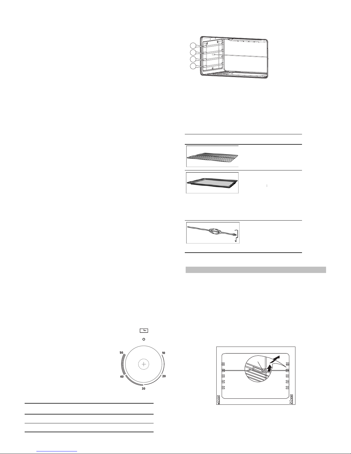
Turn the oven knob to the right and place it on the grill position .
The grill pan should be located on the top oven shelf position.
Always preheat the grill on full for 3-5 minutes before inserting
the food.
The user can change the shelves, depending on his personal
whishes and on the different food.
To remove the shelves from the oven, pull them forward you,
tilt front end upward and pull them out.
To replace it in the opposite manner as before.
Install shelves by locating them in the horizontal guide rails on
the oven walls. The raised portion of the shelf is to be facing the
rear wall of the oven.
Bump
②
Automatic Mode
Use this mode for setting oven's continuous time and end
time, which means make an appointment to boot. When the
time is over ,it will automatically turn off the heating and the
buzzer is
buzzing to inform the user.
Press K2 twice to get into the continuous time setting mode
under the common mode, press K2 again to get into the end
time setting mode.
When the continuous time setting is ok or the end time setting
is ok, then press K2 to get into the other kind of automatic
program time setting, "Auto-programming Icon" flashes, ”
press K1 and K3 to ad just continuous time and end time.
5s after automatic
program setting, it will automatically work,
and "Auto-programming Icon" keeps lighting up. Turn off the
relay conntact, and the icon i s dark. When work until the
starting time, the relay contact is connected, the icon is light.
When the continuous time is counting down, if the continuous
time is 0,turn off the relay contact, "Relay Operation Icon" is dark,
"Auto-programming Icon" flashes, and the buzzer is buzzing.
The continuous time and the end time under this mode will be
set as follow:
Starting time = end time
- continuous
time
For example, the present time is 2:00, set the continuous time to
3:00, and the end time to 10:00, then the starting time is 7:00
(7:00=10:00-3:00). The relay contact is connected and its icon
is light. After working for continuous 3 hours, the continuous
time is 0, turn off the relay contact,
"Relay Operation Icon" is dark,
“ "Auto-programming Icon"” flashes, the buzzer is buzzing.
Note:
1 End time >present time+ continuous time,
but 23 hours and 59 minutes
For example: the present time is 2:00, continuous time is
0:01, then
the
range for end time is 2:02 (2:02
2:00+1).
2 Continuous time ≥ 1 minute, continuous time and end time
both will be set.
3 If the continuous time is equal to 0 or the end time is equ al
to the present time it meas the automatic program is over.
4 When the automatic program is over, the continuous time
is 0, and the end time is the same with the present time.
4、Cancel Function
When semiautomatic or automatic function is starting, press K1
and K3 at the same time which can cancel the automatic mode.
( to c
ancel continuous time and end time).
>
≤
≥
Accessories
T
d
Y
w
r
Y
o
he access
o
ifferent she
ou can pull
t
ithout the
m
emoved ea
s
ou can buy
r from spec
Accessory
ries can be i
f positions.
he accesso
r
tipping. Thi
s
ily.
accessories
ialist retailer
s
nserted in t
h
ies two-thir
d
allows me
a
from the aft
e
.
Description
Baking and roasting shelf
For ovenwa
roasts, grilli
n
meals.
Enamelled
For moist c
a
frozen meal
s
roasts. Can
inserted un
d
wire rack or
used as a d
r
collect fat.
Rotary spit
For roasts a
of poultry. U
combinatio
n
enamelled
b
e oven in 4
s of the way
o
ls to be
r-sales serv
re, cake tins,
g and froze
n
baking tray
kes, pastrie
s
s
and large
also be
erneath the
rotary spit a
n
ip tray to
nd large piec
se only in
with the
aking tray.
ut
ce
,
d
s
1
2
3
4
Control knob for minute
minder
Use this control knob to set the cooking time.
Setting Meaning
>
Off
1 - 59
Cooking time in minutes
(for some models)
The minute minder is a countdown
timer which emits an audible signal
when the cooking time has elapsed.
The minute minder runs independently
of the oven.
-10-
Page 12
Using the rotary spit
The rotary spit can be used to cook joints such as rolled joints
and poultry with exc
ellent results. The meat is roasted thoroughly
and evenly.
The rotary spit function only when the switch is in position grill.
Preparing joints
Place the joint as centrally as possible on the rotary spit and
secure it at both ends with the retaining clips.
You can also truss the joint with string. With poultry, bind the ends
of the wings underneath the back and the thighs against the body.
This will prevent them from becoming too dark.
Pierce the skin on the underside of the wings to allow the fat to
escape.
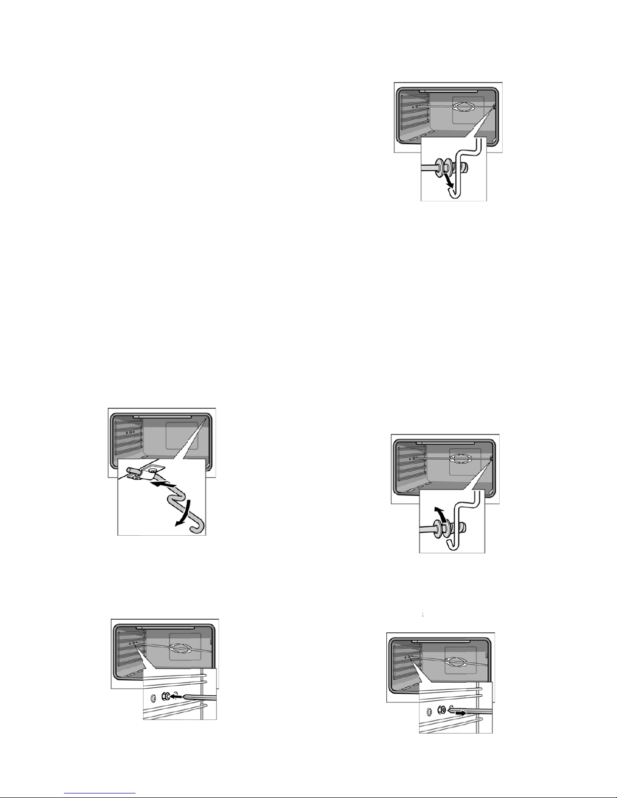
Inserting the rotary spit
I
1
G
2
3
4
Insert the rotary spit as follows:
1.
Hook the s
If you requ
G
Risk of burns
Never tou
Children m
Open the
.
If the ove n
3.
Hook the
4.
Pour a litt
pit holder into the brack eet on the ceil i
cooking compartment.
ire to preheat the oven, hook in the holder before
preheating.
ch the hot surfaces of the cooking compartment or
the heating elements.
ust be kept at a safe disstance from
at all times.
appliance door carefully. Hot steam
has been p reheated, only attach the ratary spit if
you are using an oven cloth or wearing (thermal) oven gloves.
other end int
le bit of wate
shelf pos
To attach th e spit, slide one end into the recessed adapter in the
o the holder
r into the ba
ition 1 to co
t
m
left-hand s i
r.
king tray and slide this into
llect the run-
ng of the
he appliance
ay escape.
de panel of the cooking compartment.
off fat.
Removing the rotary spit
G
R
N
CChildren must be kept at a safe distance from the appliance
OOpen the appliance door carefully. Hoot steam may escape.
G
R
N
A
R
1
isk of burns.
Never touch the hot surfaces of the c oo
at all times.
isk of burns.
ever touch the rotary spit or other accessories directly
they are hot.
lways wear oven gloves or heat-resistant gloves when
handling hot accessories.
R
emove the rotary spit as follows:
.
Carefully
or the heati ng elements.
o
pen the ap
p
spit
liance door
from the h o
l
oking
. Carefully remove the rotary
l
der.
2
3
.
Carefully
3
.
Take out
t
withdraw the
he baking tr
a
rotary spit f
the side panel and remove it from the oven.
ay.
rom the recessed adapter in
cc
ompartment
-11-
Page 13
Before cleaning the appliance, close the gas stopcock and unplug
appliance or disconnect power at the main circuit breaker of the
electrical system.
Do not clean the appliance surfaces when still hot.
Always clean off spillage as quickly as possible to prevent burning
on which will make removal more difficult. Wash with a clean cloth
soaked in hot soapy water, rinse and dry with a soft cloth.
DO NOT USE ABRASIVES. CAUSTIC PASTES OR SPRAYS.
COARSE CLEANING PADS OR POWDERS. DO NOT USE
EXCESSIVE WATER WHEN CLEANING YOUR OVEN IN ORDER
TO AVOID WATER PRESSING THROUGH CLEFTS INTO THE
BACK OF CONTROLS PANEL OR OF THE UNIT.
NOTE: A steam cleaner is not to be used for cleaning this
appliance .
Pan supports and burners
The burner heads can be removed for cleaning.
NB Do not drop hot burner caps in cold water.
Because of the rapid cooling they might get damaged.
Lift off and soak for about 10 minutes in hot water with a little
detergent. After having cleaned and washed them, dry them
carefully.
Make sure that no burner holes are clogged.
Clean the burners once a week or more frequently if necessary.
Make sure you have reassembled the burners correctly.
Pan supports can be washed by hand or in a dishwasher.
Remember to remove rubber feet (if fitted) prior to washing.
Refit them afterwards.
Do not use harsh abrasive cleaners or sharp metal scrapers to
clean the oven door glass since they can scratch the surface,
which may result in shattering of the glass.
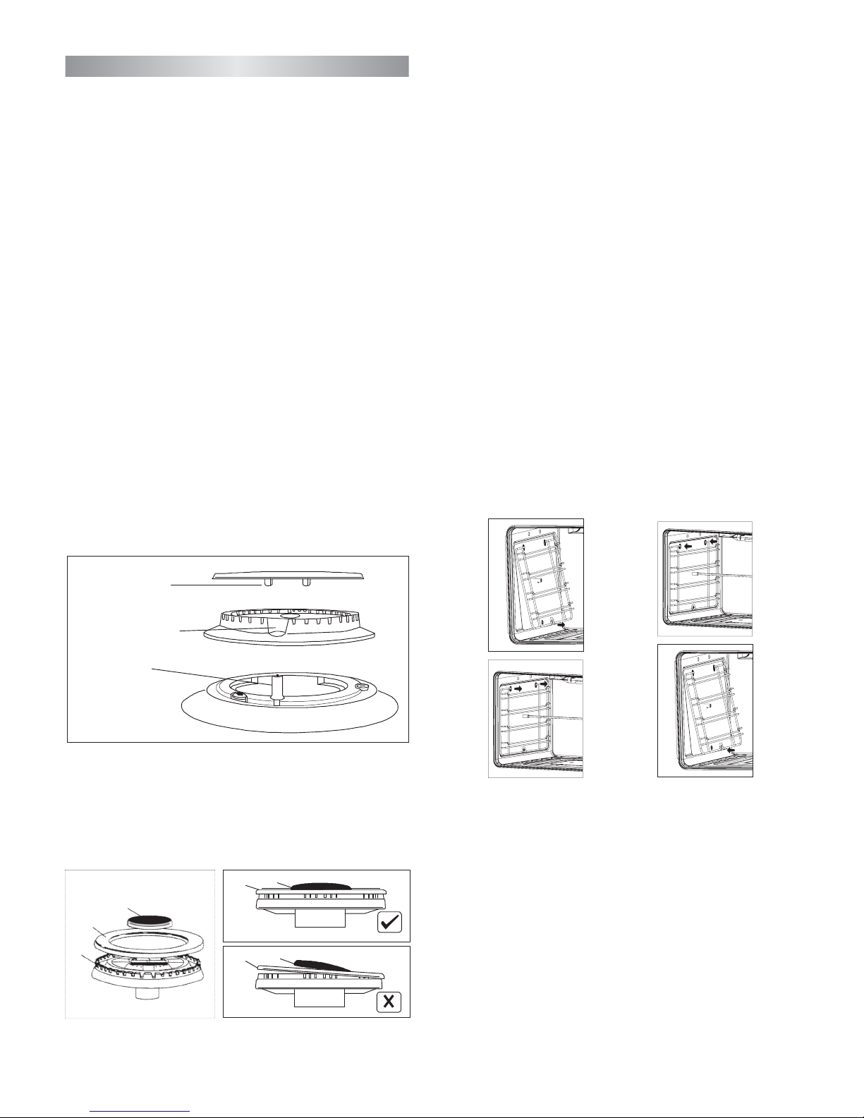
For a triple crown burner, make sure head "C" and covers "A"
and "B" are properly placed on their seats as figure E and not offcentered as in figure F.
Daily
Regular wiping down directly after use prevents dirt from burning
on. Clean the appliance with water and a detergent or all purpose
cleaner.
Avoid using too much water to prevent it entering the burner or
ventilation openings.
Oven accessories (shelves, trays etc) should be washed in mild
detergent solution and should not be treated with abrasives. The
oven interior panels should be cleaned with mild detergent solution,
mild cream cleaners or a moist soap pad.
lnstall shelves by locating them in the horizontal guide rails on
the oven walls.
The raised portion of the shelf is to be facing the rear wall of the
oven.
IMPORTANT
Do not use excessive water when cleaning the oven and avoid
water passing through the fan grill or ducts in the oven back .
Avoid letting grease deposit collect around the upper heating
element: it will cause smoking and may start a fire.
Fig. G
Fig. H
B
A
Fig. E
B
A
Fig. F
A
BC
burner
cap
locating pegs
notch
for electrode
in burner head
electrode
CLEANING
Removing the hook-in
racks
Inserting the hook-in rack
Y
t
T
c
T
1
2
ou can re
m
hem separa
he hook-in
ooking co
m
o remove t
h
.
Undo the
The lowe
r
.
Take hol
d
on the sc
r
ove the hoo
k
t
ely.
racks are all
partment at
f
e hook-in r
a
screw on th
e
hooks of th
e
of the top o
f
ew on the b
o
k-in racks in
fixed to the
f
our points.
cks, procee
d
bottom the
hook-in ra
c
the hook-in
ttom the ho
order to cle
a
w
alls of the
as follows:
hookin rack
k are releas
rack and sc
r
ok-in rack a
g
n
ed.
ew
ain.
T
1
2
o reinsert t
h
.
Insert the
side pan
e
.
Pull the h
o
the lower
e hook-in r
a
upper hook
s
l.
ok-in rack sl
hooks into t
h
cks, procee
d
into the dril
ightly down
w
e drill holes
as follows:
l holes in th
e
ards and in
s
.
ert
( Fig. G )
( Fig. H )
-12-
Page 14
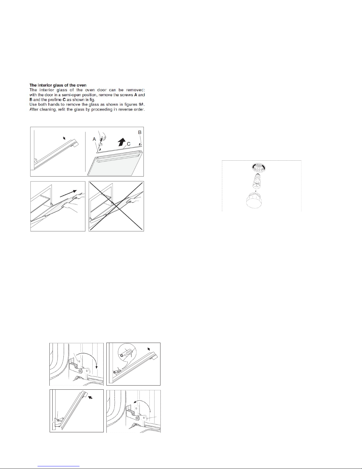
Removal of oven door
In-depth cleaning of the oven becomes more convenient if the
door is rem ove d f ollow i ng the inst r uct i o n s bel ow:
1 open the oven door completely.
2 flip the hinge hooks "A" outwards (see Fig. 5B).
3 shut the oven door slowly until it reaches hooks "A", making
sure these are locked into slots "B" of the oven door, as shown
in Fig. 5C. Remove the glass FIg. 5A (only for models where
present).
4 Using both hands, push the oven door lightly inwards, to enable
the door hinges "C" to come away from the slots "D" (see Fig.
5D) and pull the door towards you until it is released from the
oven.
After cleaning it, reposition it correctly following the abovesteps
in the reverse order and flipping hooks "A" inwardsbefore you shut
the oven door (Fig. 5E).
CAUTION:
Do not use rough or abrasive materials or sharp metal scrapers
to clean the glass doors of the oven since they may scratch
the surface and cause the glass to break.
WARNINGS
Before performing any repair or operation, switch the
appliance off and close the gas tap.
The manufacturer declines all responsibility for any damage to
persons, animals or things caused by failure to observe the rules
indicated above. In case it is necessary to repair or replace the
inside components, act as follows:
WARNINGS
Isolate the cooker from the electricity supply before attempting
to replace the oven lamp.
The oven lamp used is of a special type withstanding high
temperatures. To replace it, act as follows: disassemble the
protecting glass (A) and replace the burnt lamp with one of the
same type. Reassemble the protecting glass.
A
Fig. 5E
C
D
Fig. 5D
A
B
A
Fig. 5C
A
Fig. 5B
Cleaning the interior glass of the oven
Note
T
Fig..
he interior g
glass by p
In some mod
4
lass of the o
in the semi-
roseeding i
els, the glas
refittin
ven door ca
-open positio
After clea
n reverse ord
s is screenp
g the glass m
when th
n be remove
n, use both hands to remove the glass.
aning, refit th
er.
rinted. In this case, when
ake sure the screenprinted part is legible
e oven door is opened.
d:
e
with the door
4
-13-
Page 15
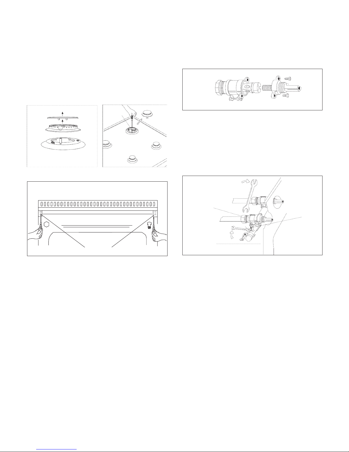
Fig. 6
V
Fig. 7
D
V
7
Disassembly of the worktop must only be done by a qualified
service technician
DISASSEMBLE OF WORK-TOP
ln case it is necessary to repair or replace the inside components,
act as follows:
Remove the grids, remove burners and flame-spreaders (see
Fig. 6), unscrew the visible screws "V" placed on the work-top
(see Fig. 7). Disassemble the work-top by
unscrewing the rear
screws "A" (see Fig. 8 according to the models). ln this
way it is possible to lift the work-top and to reach the inside
components.
GREASING OF TAPS
If a tap becomes hard to be turned, grease it using a specific
grease withstanding high temperatures. Act as follows: open the
work-top and disassemble also the control panel as described on
the previous paragraph. Unscrew the two fixing screws from the
burner body (see picture) and remove the cone.
TAPS REPLACEMENT
Act as follows: open the work-top and disassemble also the control
panel as described on the previous paragraph. Unscrew screw
nut D of the gas tube supplying the burner. Unscrew screw V
fixing the tap to the bridle and remove it (see picture).
Note: Every time the tap is replaced, it is necessary to replace
the seal gasket too check the connection seal by means of soapy
water.
Clean the cone and its slot by means of a cloth soaked with solvent.
Slightly grease the cone with the relevant grease, put it in its slot,
and turn it some times. Remove the cone again, remove the excess
grease making sure the gas entries are not obstructed by grease
residue. Assemble everything carefully in the opposite direction
check the connection seal by means of soapy water.
A
Fig. 8
-14-
Page 16

Do not use the appliance as a space heater.
If you smell gas
Open a window. Do not use any electrical switches.
Immediately extinguish naked flames. Isolate appliance from
gas mains supplies via the isolation stopcock. Contact local
gas authority or emergency services as appropriate. In the
event of food fire. Isolate appliance from electric I gas mains
supplies if safe to do so. Try to extinguish flames with the
appropriate equipment (fire blanket or extinguishing foam).
Do not use water on cooking fat I oil fires.
If in difficulty call emergency services.
• Do not store or use flammable products or aerosol containers
near the hotplate or burners.
• Never flambe, under an extractor - even if the ventilator is
switched off.
The high flames can cause fire.
For your safety and that of your children
• Do not store items that are attractive to children above or near
the appliance.
• Keep children well away from the appliance:
do not forget that some parts of the appliance or of the pans
become very hot and dangerous during use, and will take time
to cool down.
• When cooking, do not use clothes that could catch fire and
cause serious injury.
• Some "Wok" cooking pots are unstable. Check with the
manufacturer before purchasing.
• Avoid using unstable and misshapen pans which may tilt easily
and pans with a very small base diameter, e.g. milk pans, single
egg poachers. The minimum pan diameter recommended is
125mm (5"). Smaller pans will be unstable.
Very large pans may cause walls or knobs to overheat. Using
pans which are too big may deform the control knobs or discolour
the walls. This is not covered by the guarantee.
• Carefully place all pans centrally over the burners.
• Always position pan handles safely away from the front of the
hotplate and out of danger, particularly from small children.
• Never leave a chip pan unattended.
• Pans and kettles with down turned base rims should not be
used.
• Simmering aids such as asbestos or mesh mats are NOT
recommended. They will reduce burner performance and could
damage the pan supports.
• Commercially available foil spillage aids are unnecessary on
this hotplate.
Any of the following are considered to be abnormal operation
and may require servicing:
Yellow tipping of the hob burner flame.
Sooting up of cooking utensils.
Burners not igniting properly.
Burners failing to remain alight.
Burners extinguished by oven door.
Gas valves, which are difficult to turn.
Your Installer should be contacted if you have any problems with
the installation.
Before you call a service engineer please check if the problem
is something you could fix yourself. The cause of the problem is
often a simple one.
THINGS TO TRY BEFORE CALLING FOR AN ENGINEER
Burner does not burn well
Is the burner dirty or damp? Try cleaning and/or drying the burner.
Appliance not suitable for your gas type? Check the identification
plate on the hotplate base.
Burner does not ignite
Do the burners spark when you press the ignition button? If not
is the power on? See 'Checking the power supply' section further
on. If the power supply is OK then there is probably something
wrong with the ignition system.
Are the electrode or burner slots blocked by debris?
Is the burner dirty or damp? Try cleaning and/or drying the burner.
Is the burner trim correctly located?
Are the burner caps correctly located?
Check that there is not a problem with your gas supply. You can
do this by making sure that other gas appliances you may have
are working.
Pan supports
Aluminium pans may cause a metallic marking on the pan supports
which does not affect the durability of the enamel and may be
cleaned off with a metal cleaner such as 'Brasso'.
Checking the power supply
First check if the main house fuse or circuit breaker has activated.
If it's OK, test the power socket with another appliance. If the
other appliance works, then unplug the cooker and contact the
service agent
Power Failure
In the event of a failure in the electrical supply the hotplate burners
may be lit using a match.
Ventilation
The use of a gas cooking appliance results in the production of
heat and moisture in the room in which it is installed. Ensure that
the kitchen is well ventilated: keep natural ventilation holes open
or install a mechanical ventilation device, (mechanical extractor
hood). Prolonged intensive use of the appliance may call for
additional ventilation, for example opening a window, or more
effective ventilation, for example increasing the level of mechanical
ventilation where present. For more detail see the Installation
Instructions.
PROBLEM SOLVER
SOME SAFETY POINT
-15-
Page 17

OVEN DOES NOT WORK AT ALL
First, when the oven is equipped with timer, check appliance is
not programmed to turn on later. If it is, turn to manual setting (i.e.
hand symbol). If the button or scale on the timer remains in the
automatic position after use, the power supply to the oven will be
interrupted. Also, check your appliance is switched on at the
mains. Next check for an unexpected power strike by switching
on adjacent lights etc. Finally, check fuses and plug wiring. If all
these prove satisfactory, call engineer.
LIGHT BULB DOESN'T COME ON
Check bulb for looseness or burned out bulb.
Note: bulb replacement is not covered by your guarantee.
SMOKE COMING FROM OVEN
If oven is still relatively new, this problem is invariably due to
protective oil on elements. Otherwise, the answer may be oil or
fat which has become deposited on the elements during cooking.
In either event, continued use should burn away the residues. On
future occasions, try to shield food with foil or keep it further away
from element, particularly when grilling.
CLOCKITIMER DOES NOT WORK
Check to be sure range cord is plugged into outlet completely.
Check for a blown fuse or tripped circuit breaker. Check for power
outage. Check step by step operating Instructions on previous
pages.
If, after checking through this section, you cannot resolve
your problem please call the number on the warranty page
in this manual for service and spare parts.
When ordering please quote the appliance name, the colour
variant and serial number.
This information can be found on the data plate sealed inside
the front appliance drawer.
Maintenance schedule:
To ensure the appliance continues to operate at
peak performance, we recommend a routine service
call every 2 years for the life of the appliance.
FOR SPARE PARTS OR TO FIND THE ADDRESS OF
YOUR NEAREST STATE SPARE PARTS CENTRE IN AUSTRALIA
GSM Sales Pty Ltd
Street: 142-144
Suburb / City:
State / Country: , South Australia
Postcode: 5067
Telephone: +1300 373 199 AUS or +0508 123 108 NZ
SA
Adelaide
Fullarton Road,Rose Park
-16-
Page 18

WARRANTY
1.1 In this warranty:
1.1.1 Australian Consumer Law means the law as set out in Schedule 2 of the Competition and
Consumer Act 2010;
1.1.2 Company means GSM Sales Pty Ltd ABN 53 007 682 475 of 142-144 Fullarton Road, Rose
Park SA 5067. Tel 1300 373 199 AUS or 0508 123 108 NZ Email [email protected];
1.1.3 Consumer means a “consumer” as that term is defined in Section 3 of the Australia
n Consumer
Law as the original purchaser of a Bellini product;
1.1.4 Consumer Guarantees means the guarantees under the Australian Consumer Law;
1.1.5 You means the Consumer.
1.2 Nothing in this warranty affects any person’s rights under the Australian Consumer Law. The benefits to
any Consumer under this warranty are in addition to the rights and remedies available under any Consumer
Guarantees.
1.3 Subject to the other clauses of this warranty, the Company warrants to the Consumer that the Bellini
product will be free of manufacturing defects and will perform to the Company’s specifications.
1.4 The benefit of this warranty extends only to the Consumer as original purchaser of a Bellini product which is
installed in a residential property.
1.5 This warranty commences on the date of purchase of the Bellini product by the Consumer and continues for
the benefit only of the Consumer until the expiry of two (2) years (Warranty Period).
1.6 If within the Warranty Period a manufacturing defect is discovered in the Bellini product or it fails to perfo rm
to the Company’s specifications as a result of some defect in materials, components or workmanship
(Defect) then the Company will, at its option, repair the Bellini product or supply a replacement Bellini
product free of charge. A replacement Bellini product may differ from the original product purchased by the
Consumer.
1.7 This warranty will not apply to any Bellini product:
1.7.1 Installed by any person other than a qualified tradesperson; or
1.7.2 Subjected to misuse, neglect, negligence or accidental damage; or
1.7.3 Operated in any way contrary to any operating or maintenance instructions; or
1.7.4 Improperly handled, installed or maintained; or
1.7.5 Altered or modified prior to or after installation; or
1.7.6 Damaged directly or indirectly by power surges, electrical storm damage or con nection to incorre ct
power supply
IN ORDER TO MAKE A CLAIM UNDER THIS WARRANTY THE
CONSUMER MUST CALL 1300 373 199 (AUSTRALIA) OR 0508 123 108
(NEW ZEALAND) TO CONNECT TO THE NEAREST AUTHORISED CENTRE
TheAustralianConsumerLawrequirestheinclusionofthefollowingstatement
withthiswarranty:
Our goods come with guaranteed that cannot be excluded under the Australian Consumer Law. You are
entitled to a replacement or refund for a major failure and for compensation for any other reasonably
foreseeable loss or damage. You are also entitled to have the goods repaired or replaced if the goods
fail to be of acceptable quality and the failure does not amount to a major failure.
-17-
Page 19

1.8 You must provide proof of your purchase of the Bellini product and the date of purchase in order to obtain
the benefit of this warranty.
1.9 If you live outside the service area of the Company or one of its service agents, this warranty does not cover
the cost of transport of the Bellini product for service nor the service agent’s travelling costs to and from your
home.
1.10 If you are required to transport the Bellini product to the Company or its service agent, you must ensure it i s
safely disconnected by a qualified tradesman and securely packed and insured. The Company does not
accept any responsibility for loss or damage of the Bellini product prior to it being received by the Company
or its service agent.
1.11 You will be responsible for all costs of returning a Bellini product to the Company and for redelivery of the
Bellini product by the Company (whether it is the original or a repaired and/o r a replacement Bellini produ ct)
and for any other expenses you incur in claiming under this warranty.
1.12 The Company or its service agent will examine any Bellini product and if the Company deter mines t hat it is
defective through no fault of the Owner and is otherwise undamaged, the Compan y will repair or replace the
Bellini product in accordance with this warranty.
DO NOT SEND IN THIS WARRANTY
Fill out the following details and file with your purchase invoice.
RETAIN & FILE WITH YOUR RECEIPT
Your Purchase Receipt/Invoice is proof of date of purchase. If you are unable to establish the date of purchase,
or if the fault is not covered by this warranty, or if the product is found to be in working order, you will be required
to bear all service call charges.
GSM Sales Pty Ltd reserves the right to discontinue items, modify designs and change specifications without
incurring obligation.
Whilst every effort is made to ensure that descriptions, specifications and other information in this publication is
correct, no warranty is given in respect thereof and the company shall not be liable for any errors therein.
Purchased from:
Co. Name:
Address:
Date of Purchase:
Serial number:
NOTE: Consistent with our continuing product development policy, improvements may have been made
which render the contents of this packa ging slightly different to that shown.
FOR WARRANTY SER VICE CALL 1300 373 199 (AUSTRALIA)
OR 0508 123 108 (NEW ZEALAND) TO CONNECT YOU TO THE NEAREST
AUTHORI
SED SERVICE CENTRE
-18-
Page 20

 Loading...