

Page 1
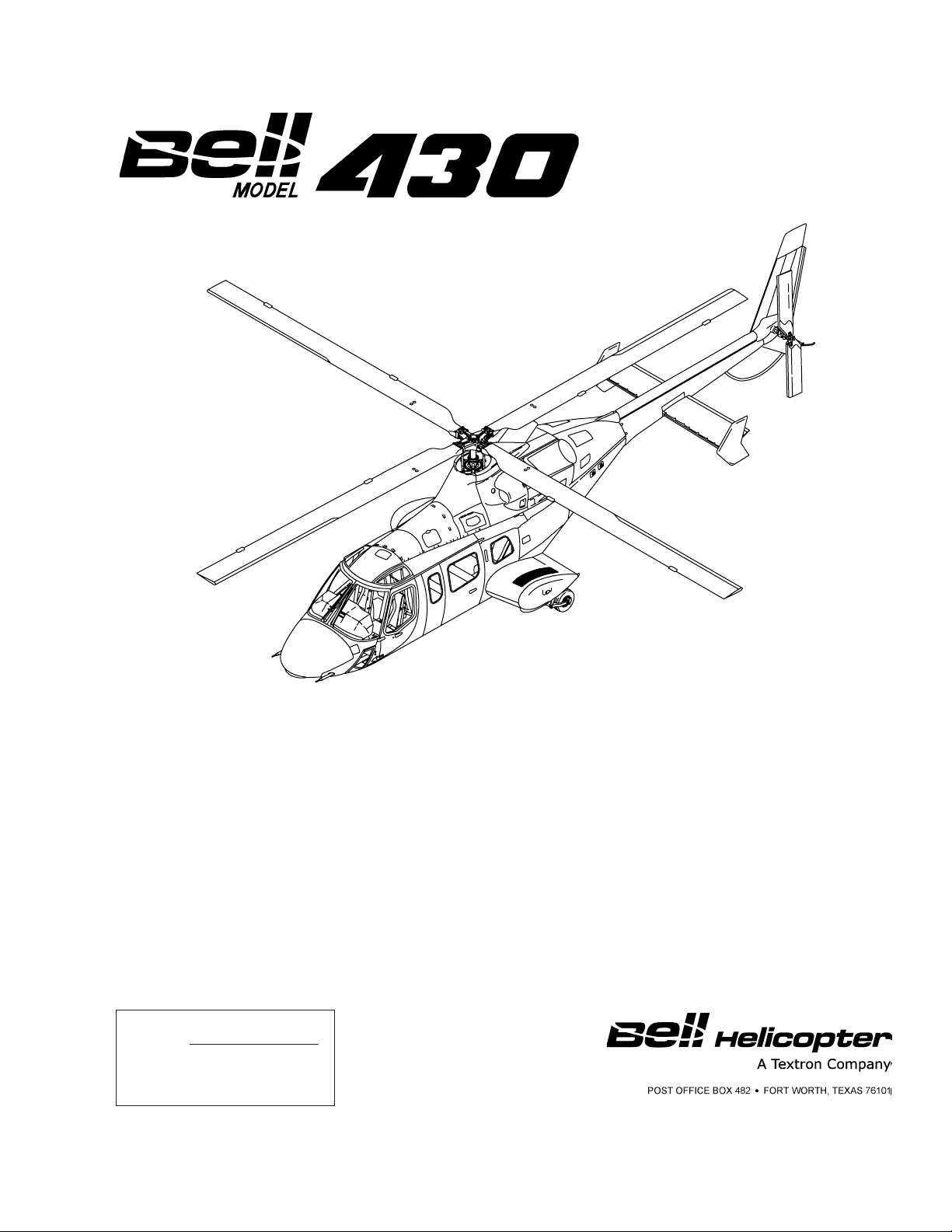
BHT-430-MM-2
COPYRIGHT NOTICE
COPYRIGHT
2012
BELL
®
HELICOPTER TEXTRON INC.
AND BELL HELICOPTER TEXTRON
CANADA LTD.
ALL RIGHTS RESERVED
The instructions set forth in this manual, as supplemented or modified by Alert Service Bulletins (ASB) or
other directions issued by Bell Helicopter Textron Inc. and Airworthiness Directives (AD) issued by the
applicable regulatory agencies, shall be strictly followed.
MAINTENANCE MANUAL
VOLUME 2
HANDLING AND SERVICING
NOTICE
REISSUE — 30 JUNE 1999
REVISION 19 — 1 NOVEMBER 2012
Page 2

BHT-430-MM-1
PROPRIETARY RIGHTS NOTICE
These data are proprietary to Bell Helicopter Textron Inc. Disclosure,
reproduction, or use of these data for any purpose other than helicopter
operation or maintenance is forbidden without prior written authorization from
Bell Helicopter Textron Inc.
DESTINATION CONTROL STATEMENT
WARNING — This document contains technical data whose export is restricted
by the Arms Export Control Act (Title 22, U.S.C., Sec 2751, et. seq.) or the Export
Administration Act of 1979, as amended, Title 50, U.S.C., App. 2401 et. seq.
Violations of these export laws are subject to severe criminal penalties.
Disseminate in accordance with provisions of DoD Directive 5230.25.
Additional copies of this publication may be obtained by contacting:
Commercial Publication Distribution Center
Bell Helicopter Textron Inc.
P. O. Box 482
Fort Worth, Texas 76101-0482
PN Rev. 20 20 SEP 2013 Export Classification C, ECCN EAR99
Page 3

WARNING
THIS MANUAL APPLIES ONLY TO HELICOPTERS AND COMPONENTS
MAINTAINED IN ACCORDANCE WITH BELL HELICOPTER TEXTRON
(BELL) APPROVED PROCEDURES USING BELL APPROVED PARTS.
ALL INSPECTION, REPAIR AND OVERHAUL PROCEDURES PUBLISHED
BY BELL, INCLUDING PART RETIREMENT LIFE, ARE BASED SOLELY ON
THE USE OF BELL PARTS THAT HAVE BEEN MAINTAINED USING BELL
APPROVED DATA. THE DATA PUBLISHED HEREIN OR OTHERWISE
SUPPLIED BY BELL IS NOT APPLICABLE TO NON-BELL PARTS OR
PARTS THAT HAVE BEEN REPAIRED USING DATA AND/OR PROCESSES
NOT APPROVED BY BELL.
BELL IS NOT RESPONSIBLE FOR ANY PART OTHER THAN THOSE THAT
IT HAS APPROVED.
BEFORE PERFORMING ANY PROCEDURE CONTAINED IN THIS MANUAL
YOU MUST INSPECT THE AFFECTED PARTS AND RECORDS FOR
EVIDENCE OF ANY MANUFACTURE, REPAIR, REWORK OR USE OF A
PROCESS NOT APPROVED BY BELL.
IF YOU IDENTIFY OR SUSPECT THE USE OF PARTS NOT AUTHORIZED
BY BELL, EITHER REMOVE THE AFFECTED ITEM FROM THE AIRCRAFT
OR OBTAIN INSTRUCTIONS FOR CONTINUED AIRWORTHINESS FROM
THE MANUFACTURER OR THE ORGANIZATION THAT APPROVED THE
REPAIR.
BHT-430-MM-1
20 SEP 2013 Rev. 20 WarningExport Classification C, ECCN EAR99
Page 4

BHT-430-MM-1
Flying smart means that no matter where you are, or what time it is, you can make a call
and get additional information, clarification, or advice on a technical or operational issue
concerning your helicopter or information contained in our Technical Publications.
Product Support Engineering (PSE) is just a phone call away and may be contacted as
follows:
CUSTOMER SUPPORT AND SERVICES
Model 206 or 407
Phone: 450-437-2862 or 800-363-8023 (U.S./Canada)
Fax: 450-433-0272
E-mail: [email protected]
Model 222, 230, 427, 429, or 430
Phone: 450-437-2077 or 800-463-3036 (U.S./Canada)
Fax: 450-433-0272
E-mail: [email protected]
Model 204, 205, 212, or 412
Phone: 450-437-6201 or 800-363-8028 (U.S./Canada)
Fax: 450-433-0272
E-mail: [email protected]
Model 214, 210, HUEY II and All Bell’s Active and
Surplus Military Medium Helicopter Models
Phone: 817-280-3548
Fax: 817-280-2635
E-mail: [email protected]
Model OH-58, TH-67, TH-57, Both Active and
Military
Phone: 817-280-3548
Fax: 817-280-2635
E-mail: [email protected]
Surplus
For additional information on Customer Support and Services as well as Product Support
Engineering (PSE) and your local Customer Service Engineering (CSE) network, please
access http://www.bellhelicopter.com/support.
CSS Rev. 20 20 SEP 2013 Export Classification C, ECCN EAR99
Page 5

H ELP
E VALUATE
L OGISTICS
P UBLICATIONS
Have you found something wrong with this manual an
error, an inconsistency, unclear instructions, etc.? Although
we strive for accuracy and clarity, we may make errors on
occasion. If we do and you discover it, we would appreciate
your telling us about it so that we can change whatever is
incorrect or unclear. Please be as specific as possible.
Your complaint or suggestion will be acknowledged and we
will tell you what we intend to do.
You may use the enclosed Customer Feedback form, as
applicable, to inform us where we have erred.
Your assistance is sincerely appreciated.
Export Classification C, ECCN EAR99
Page 6

Page 7
CUSTOMER FEEDBACK
RETURN VIA FAX TO PRODUCT SUPPORT ENGINEERING (450) 433-0272,
or MAIL TO THE ADDRESS ON THE NEXT PAGE.
Manual Title:
Manual Number (if assigned):
Date of Issue:
Date of Last Revision:
Section, Chapter, Paragraph Affected:
Your Feedback:
Now Reads:
Should Read:
Your Name:
Address:
Position: Teleph one No.:
Company:
Fax No.:
Reference No. (your initials and date):
(If you choose to mail this form, fold in thirds with address exposed, tape and mail.)
Export Classification C, ECCN EAR99
Page 8
TAPE HERE
From
POSTAGE
NECESSARY
Product Support Engineering
12,800 rue de lAvenir
Mirabel, Québec, Canada, J7J 1R4
FOLD ON DOTTED LINES AND TAPE
TAPE HERE
Export Classification C, ECCN EAR99
Page 9

IMPORTANT
HELICOPTER SALES NOTICE
Please complete this form and return by mail, e-mail ([email protected]), or fax (817-280-6466,
Attention: CPDC). This will ensure that the new owners/operators receive updates to their Bell
Helicopter Textron Technical Manuals and Bulletins.
Model of Helicopter Sold or Purchased ___________________________________________
Serial and Registration Number _________________________________________________
Name of New Owner (company or individual) ______________________________________
Name of New Operator _______________________________________________________
Future Publications to be mailed to this address:
Address ____________________________________________________________________
City _______________________________________________________________________
State/Province _______________________________________________________________
Zip/Postal Code _____________________________________________________________
Country ____________________________________________________________________
Fax No. ___________________________ Telephone No. ____________________________
E-mail Address ______________________________________________________________
Register for access to electronic publications at www.bellhelicopter.net
Export Classification C, ECCN EAR99
Page 10
TAPE HERE
From
NO POSTAGE
NECESSARY
IF MAILED
IN THE
UNITED STATES
COMMERCIAL PUBLICATION DISTRIBUTION CENTER
P.O. BOX 482
FORT WORTH, TEXAS 76101-0482
FOLD ON DOTTED LINES AND TAPE
BUSINESS REPLY MAIL
FIRST CLASS PERMIT NO. 1744 FORT WORTH, TEXAS
Export Classification C, ECCN EAR99
Page 11

SPARE PARTS WARRANTY
ONE YEAR/1,000 HOURS PRORATED
WARRANTY AND REMEDY: Seller warrants each new helicopter part or helicopter part reconditioned by seller to be free from defect
in material and workmanship under normal use and service and if installed on Bell model helicopters. Sellers sole obligation under this
warranty is limited to replacement or repair of parts which are determined to Sellers reasonable satisfaction to have been defective
with 1,000 hours of operation or one (1) year after installation, whichever occurs first and reimbursement of reasonable freight charges.
After 200 hours of use, there will be a prorated charge to the Purchaser for replacement parts (prorating the hours of total use against
the then applicable part life or 2,000 hours, whichever is the lesser). Defective parts must be reported in writing to the Sellers Warranty
Administration within 90 days of being found defective. Replacement of parts may be with either new or reconditioned parts, at Sellers
election. Warranty adjustment is contingent upon the Purchaser complying with the Warranty Remedies as described in the
Commercial Warranty Information brochure and the Sellers Warranty Administration disposition instructions for defective parts. Failure
to comply with all of the terms of this paragraph may, at Sellers sole option, void this warranty.
NOTE: Parts, components and assemblies of all new helicopters may have been restored or reworked due to mars, blemishes, dents
or other irregularities during the manufacturing process. Such restoration and/or rework is permitted under Sellers approved
manufacturing and engineering processes and guidelines. The restoration and/or rework so completed does not render such items
defective in material or workmanship.
THIS WARRANTY IS GIVEN AND ACCEPTED IN PLACE OF (i) ALL OTHER WARRANTIES OR CONDITIONS, EXPRESS OR
IMPLIED, INCLUDING BUT NOT LIMITED TO THE IMPLIED WARRANTIES OR CONDITIONS OF MERCHANT ABILITY AND
FITNESS FOR A PARTICULAR PURPOSE AND (ii) ANY OBLIGATION, LIABILITY, RIGHT, CLAIM OR REMEDY IN CONTRACTOR
IN TORT (DELICT), INCLUDING PRODUCT LIABILITIES BASED UPON STRICT LIABILITY, NEGLIGENCE, OR IMPLIED
WARRANTY IN LAW.
This warranty is the only warranty made by Seller. The Purchasers sole remedy for a breach of this warranty or any defect in a part is
the repair or replacement of helicopter parts and reimbursement of reasonable freight charges as provided herein. Seller excludes
liability, whether as a result of a breach of contract or warranty, negligence or strict product liability, for incidental or consequential
damages, including without limitation, damage to the helicopter or other property, costs and expenses resulting from required changes
or modifications to helicopter components and assemblies, changes in retirement lives and overhaul periods, local customs fees and
taxes, and costs or expenses for commercial losses or lost profits due to loss of use or grounding of helicopters or otherwise.
Seller makes no warranty and disclaims all liability in contract or in tort (delict), including, without limitation, negligence and strict tort
(delictual) liability, with respect to work performed by third parties at Purchasers request and with respect to engines, engine
accessories, batteries, radios, and avionics, except Seller assigns each manufacturers warranty to Purchaser to the extent such
manufacturers warranty exists and is assignable.
This warranty shall not apply to any helicopter part which has been repaired or altered outside Seller s factory in any way so as, in
Sellers judgment, to affect its stability, safety or reliability, or which has been subject to misuse, negligence or accident, or which has
been installed in any aircraft which has been destroyed unless that helicopter has been rebuilt by Bell. A list of destroyed aircraft is
obtainable from Bell Product Support. Repairs and alterations which use or incorporate parts and components other than genuine Bell
parts or parts approved by Bell for direct acquisition from sources other than Bell itself are not warranted by Bell, and this warranty shall
be void to the extent that such repairs and alterations, in Sellers sole judgment, affect the stability, safety or reliability of the helicopter
or any part thereof, or damage genuine Bell or Bell-approved parts. No person, corporation or organization, including Bell Customer
Service Facilities, is authorized by Seller to assume for it any other liability in connection with the sale of its helicopters and parts.
NO STATEMENT, WHETHER WRITTEN OR ORAL, MADE BY ANY PERSON, CORPORATION OR ORGANIZATION, INCLUDING
BELL CUSTOMER SERVICE FACILITIES MAY BE TAKEN AS A WARRANTY NOR WILL IT BIND SELLER.
Seller makes no warranty and disclaims all liability with respect to components or parts damaged by, or worn due to, corrosion. Seller
makes no warranty and disclaims all liability for consumables (wear items) which are defined as items required for normal and routine
maintenance or replaced at scheduled intervals shorter than the warranty period. Consumables include but are not limited to engine
and hydraulic oil, oil filters, packings and o-rings, anti-corrosion and/or sealing compounds, brush plating material, nuts, bolts, washers,
screws, fluids, compounds, and standard aircraft hardware that is readily available to aircraft operators from sources other than Seller.
All legal actions based upon claims or disputes pertaining to or involving this warranty including, but not limited to, Sellers denial of any
claim or portion thereof under this warranty, must be filed in the courts of general jurisdiction of Tarrant County, Texas or in the United
States District Court for the Northern District of Texas, Ft. Worth Division located in Ft. Worth, Tarrant County, Texas. In the event that
Purchaser files such an action in either of the court systems identified above, and a final judgment in Sellers favor is rendered by such
court, then Purchaser shall indemnify Seller for all costs, expenses and attorneys fees incurred by Seller in defense of such claims. In
the event Purchaser files such a legal action in a court other than those specified, and Seller successfully obtains dismissal of that
action or transfer thereof to the above described court systems, then Purchaser shall indemnify Seller for all costs, expenses and
attorneys fees incurred by Seller in obtaining such dismissal or transfer.
January 2007
BHT-430-MM-1
Export Classification C, ECCN EAR99
20 SEP 2013 Rev. 20 Warranty
Page 12

Page 13
TC APPROVED BHT-430-MM-2
TABLE OF CONTENTS
Paragraph Chapter/Section Page
Number Title Number Number
FIGURES
Figure Page
Number Title Number
TABLES
Table Page
Number Title Number
Chief Engineering
Aircraft Certification
Transport Canada
The Airworthiness Limitations Schedule is approved by the Minister and specifies the maintenance required by
any applicable airworthiness or operational rules unless an alternative program has been approved by the
Minister.
CHAPTER 4 — AIRWORTHINESS LIMITATIONS SCHEDULE
AIRWORTHINESS LIMITATIONS SCHEDULE
4-1 Airworthiness Limitations Schedule ............................................... 4-00-00 5
4-1 Main Rotor Yoke — 100-Hour and 600-Hour Inspection .................................... 11
4-2 Main Rotor Yoke Edges — Inspection ................................................................ 12
4-3 Pylon Fluid Mount — Inspection ......................................................................... 13
4-4 Main Rotor Yoke — 2500-Hour Inspection ......................................................... 14
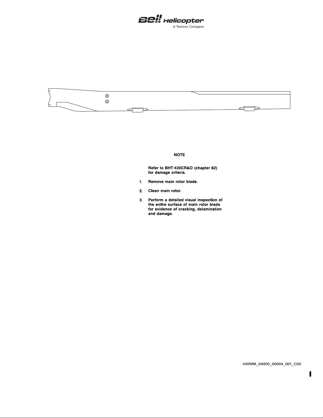
4-5 Main Rotor Blade — Inspection .......................................................................... 15
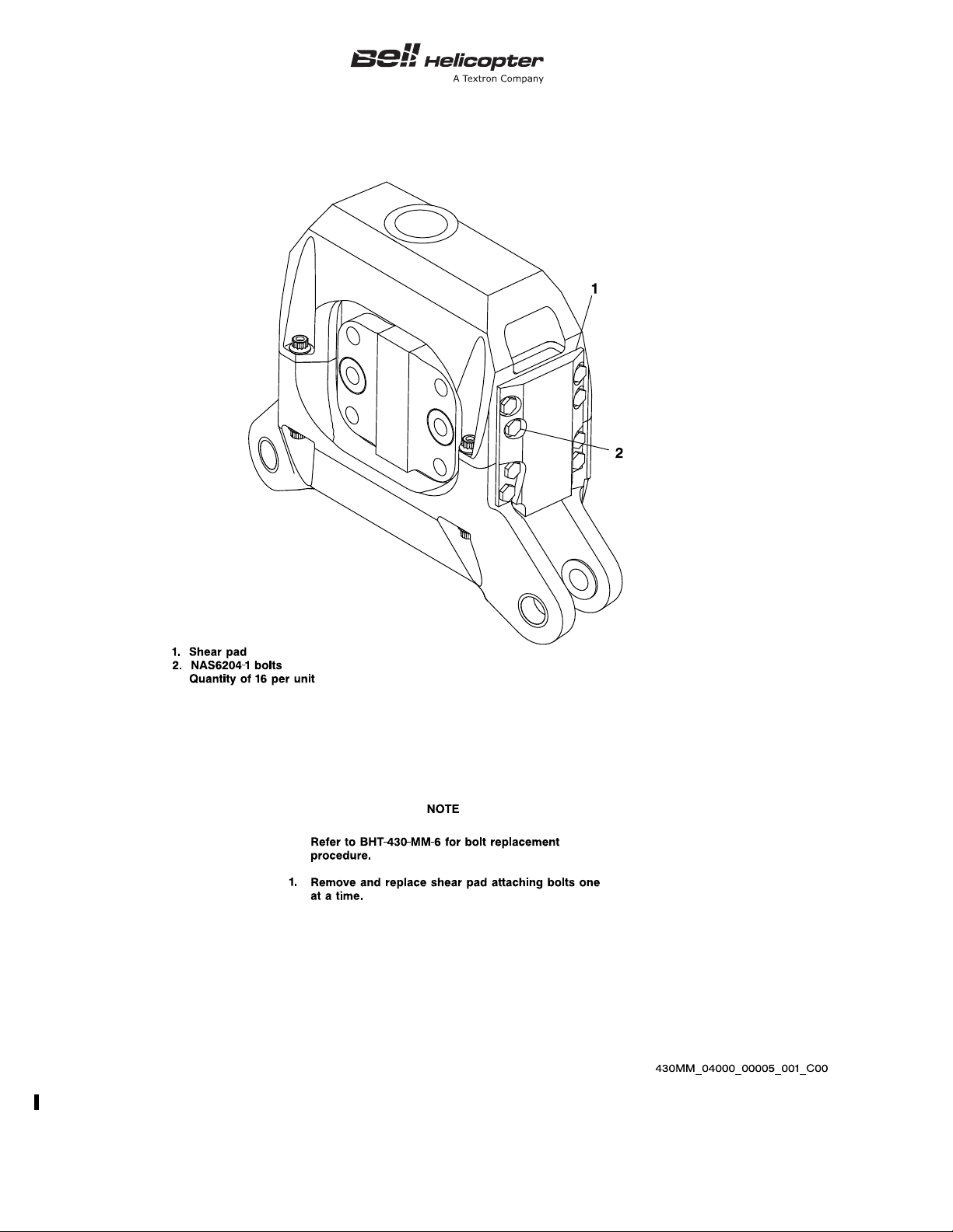
4-6 Pylon Fluid Mount — Torque Shear Pad Bolt Replacement............................... 16
4-1 Airworthiness Limitations Schedule .................................................................... 6
4-2 Inspection Limitations Schedule ......................................................................... 10
ECCN EAR99
1 NOV 2012 Rev. 19 Page 1
4-00-00
Page 14
BHT-430-MM-2 TC APPROVED
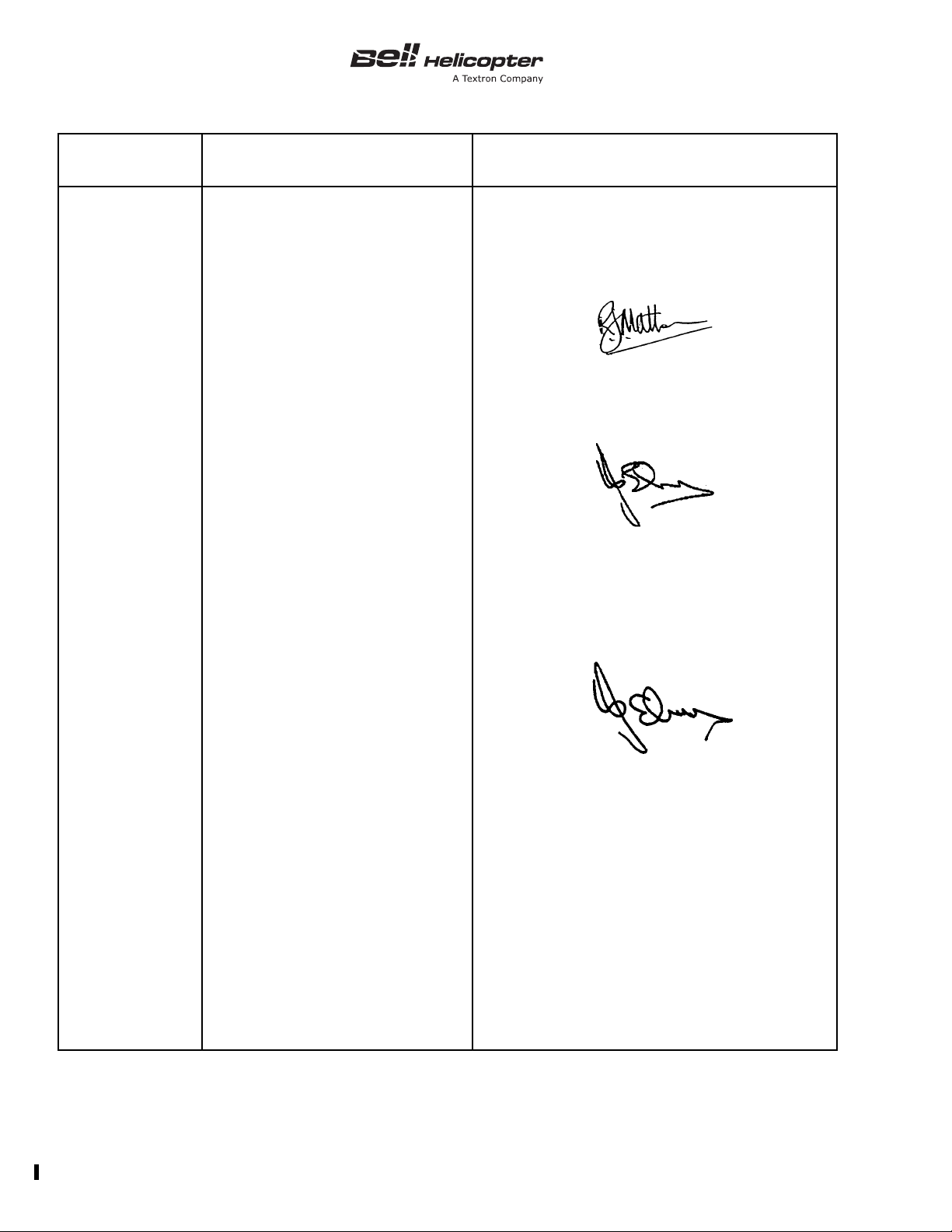
REVISION NO. DATE OF SIGNATURE APPROVAL SIGNATURE
Original
1 15 July 1996 N/A
2 30 October 1996
Reissue 16 April 1997 N/A
Reissue 6 July 1999
1 15 October 1999 N/A
2 10 December 1999 N/A
3 15 December 1999
4 7 January 2000 N/A
5 1 July 2000 N/A
6 1 August 2002 N/A
7 22 August 2002 N/A
8 16 December 2002 N/A
9 7 November 2003 N/A
4-00-00
Page 2 Rev. 19 1 NOV 2012
ECCN EAR99
Page 15
TC APPROVED BHT-430-MM-2
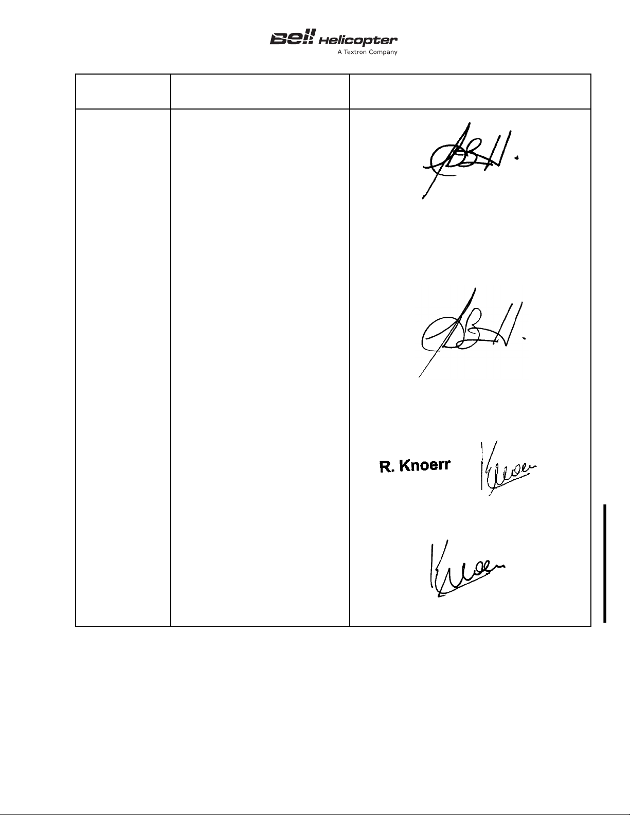
REVISION NO. DATE OF SIGNATURE APPROVAL SIGNATURE
10 2 February 2005
11 25 October 2005 N/A
12 1 May 2006 N/A
13 21 June 2006
14 15 December 2006 N/A
15 26 January 2007 N/A
16 9 January 2008
17 1 September 2009 N/A
18 9 September 2011 N/A
19 1 November 2012
ECCN EAR99
4-00-00
1 NOV 2012 Rev. 19 Page 3/4
Page 16

Page 17
TC APPROVED BHT-430-MM-2
WARNING
WARNING
NOTE
NOTE
WARNING
AIRWORTHINESS LIMITATIONS SCHEDULE
4-1. AIRWORTHINESS LIMITATIONS
SCHEDULE
ALL REPAIR AND OVERHAUL
PROCEDURES PUBLISHED BY BELL
HELICOPTER TEXTRON, INCLUDING
COMPONENT RETIREMENT LIFE, ARE
BASED SOLELY ON THE USE OF BELL
APPROVED PARTS AND PROCESSES.
IF PARTS OR PROCESSES DEVELOPED
OR APPROVED BY PARTIES OTHER
THAN BELL HELICOPTER ARE USED,
THEN THE DATA PUBLISHED OR
OTHERWISE SUPPLIED BY BELL
HELICOPTER ARE NOT APPLICABLE.
THE USER IS WARNED TO NOT RELY
ON BELL HELICOPTER DATA FOR
PARTS AND PROCESSES NOT
APPROVED BY BELL HELICOPTER. ALL
APPLICABLE INSPECTIONS AND
REPAIR METHODS MUST BE OBTAINED
FROM THE SUPPLIER OF THE PARTS
OR PROCESSES NOT APPROVED BY
BELL HELICOPTER. BELL HELICOPTER
IS NOT RESPONSIBLE FOR PARTS OR
PROCESSES OTHER THAN THOSE
WHICH IT HAS ITSELF DEVELOPED OR
APPROVED.
CONTINUED USE, EVEN INADVERTENT
USE.
WHEN A REPLACEMENT PART IS
INSTALLED, THE PART NAME, PART
NUMBER, SERIAL NUMBER, AND
CURRENT OPERATING HOURS, IF
APPLICABLE, MUST BE RECORDED IN
THE HISTORICAL SERVICE RECORD
FOR THE ASSEMBLY OR HELICOPTER.
The requirements stated in Chapter 5 are to
be complied with and the appropriate
maintenance actions are to be performed.
The airworthiness life or inspection interval
for any part number contained in this
schedule applies to all the successive dash
numbers for that component unless it is
otherwise specified.
The mandatory Airworthiness Limitation Schedule
(Ta bl e 4 -1 ) summarizes the mandatory maximum life,
in hours, years, or by Retirement Index Number (RIN)
of components with a limited airworthiness life. Parts
that are not on the schedule have an unlimited
airworthiness life. The Inspection Limitations Schedule
(Ta bl e 4 -2 ) summarizes the mandatory inspection
interval in hours.
CONTINUED USE OF ANY TIME/
CALENDAR/RIN LIFE LIMITED
COMPONENT PAST ITS STATED LIMITS
IS NOT PERMITTED AS IT COULD
SERIOUSLY AFFECT THE
AIRWORTHINESS OF THE HELICOPTER.
THE COMPONENT MUST BE REMOVED
FROM THE HELICOPTER NOT LATER
THAN THE END OF THE LIFE LIMIT. IT
MUST EITHER BE MADE
UNSERVICEABLE OR MARKED IN A
CONSPICUOUS MANNER TO PREVENT
ECCN EAR99
Refer to the engine manufacturer’s publications for the
airworthiness limitations of the power plant
components.
SOME PARTS ARE INSTALLED AS
ORIGINAL EQUIPMENT ON BOTH
MILITARY AND COMMERCIAL
HELICOPTERS AND MAY HAVE A
LOWER AIRWORTHINESS LIFE AND/OR
OVERHAUL SCHEDULE WHEN USED
ON A MILITARY HELICOPTER. IN
ADDITION, CIRCUMSTANCES
SURROUNDING THEIR USE MAY CALL
4-00-00
1 NOV 2012 Rev. 19 Page 5
Page 18
BHT-430-MM-2 TC APPROVED
CAUTION
NOTE
1
FOR OPERATION OF THE MILITARY
HELICOPTER OUTSIDE OF THE
APPROVED COMMERCIAL FLIGHT
ENVELOPE. CONSEQUENTLY, PARTS
THAT HAVE BEEN USED ON MILITARY
HELICOPTERS SHOULD NOT BE USED
ON COMMERCIAL HELICOPTERS.
The retirement life given, or the failure to
give a retirement life to a component, does
not constitute a warranty of any kind. The
only warranty applicable to the helicopter or
any component is the warranty included in
the Purchase Agreement for the helicopter
or the component.
The airworthiness lives given to the components and
assemblies are determined by experience, tests, and
AIRWORTHINESS LIFE OF SOME KIT
COMPONENTS IS NOT COVERED IN
THIS SCHEDULE. REFER TO
APPLICABLE SERVICE INSTRUCTION
(SI) OR MAINTENANCE MANUAL
SUPPLEMENT (MMS) FOR KIT
COMPONENT SCHEDULES.
the judgment of Bell Helicopter engineers. The lives
cannot be changed without the approval of the
Minister of Transport Canada.
Prior to disposing of unsalvageable helicopter parts
and materials, caution should be exercised to ensure
that the parts and material are disposed of in a manner
that does not allow them to be returned for service.
Refer to FAA Advisory Circular 21-38 for guidance on
the disposal of unsalvageable aircraft parts and
materials.
Table 4-1. Airworthiness Limitations Schedule
COMPONENT PART NUMBER AIRWORTHINESS LIFE
MAIN ROTOR
Pin Assembly 430-010-127-101 10,000
Adapter Assembly 430-010-109-101 10,000
Pitch Horn Assembly 430-010-115-101 10,000
Damper Blade Set 430-310-104-105 10,000
Shear Restraint 430-310-101-105 10,000
Clamp Plate Set 430-010-105-105 10,000
Drive Bushing 430-010-124-101 5000
Drive Plate Assembly 430-010-126-101 10,000
Bolt 20-065-08083 5000
Bolt MS21250-08083 5000
4-00-00
Page 6 Rev. 19 1 NOV 2012
ECCN EAR99
Page 19

TC APPROVED BHT-430-MM-2
1
Table 4-1. Airworthiness Limitations Schedule (Cont)
COMPONENT PART NUMBER AIRWORTHINESS LIFE
MAIN ROTOR CONTROLS
Main Rotor Pitch Link Assembly 430-010-411-105/-107 10,000
Drive Hub Assembly 430-010-410-101 10,000
Drive Idler Link Assembly 430-010-409-105 10,000
Drive Link Assembly 430-010-408-101 10,000
Rotating Ring Assembly 430-010-401-101 10,000
Non-rotating Ring Assembly 430-010-402-101 10,000
Cyclic Link Assembly 430-010-412-105 10,000
Swashplate Support Assembly 430-010-404-101 10,000
Swashplate Ball and Sleeve Assembly 430-010-403-101 10,000
Collective Lever Assembly 430-010-405-105 10,000
Collective Idler Link Assembly 430-010-407-101 10,000
Cyclic Lever Assembly 430-010-406-101 10,000
Actuator Support Assembly 222-040-125-001 5000
CONTROL SYSTEM BOLTS AND PINS
Pitch Horn to Universal Bolt 50-047C6-36 5000
Universal to Pitch Link Bolt 50-047C6-28 5000
Pitch Link to Rotating Ring Bolt 50-047C6-32 5000
Drive Hub to Drive Hub Bolt 20-057C5-19 5000
Drive Hub to Idler Link Bolt 50-047C6-99 5000
Idler Link to Drive Link Bolt 50-047C6-99 5000
Drive Link to Rotating Ring Bolt 50-047C6-49 5000
Non-rotating Ring to Cyclic Link Bolt 50-047C6-32 5000
Cyclic Link to Cyclic Lever Bolt 50-047C6-32 5000
4-00-00
ECCN EAR99
1 NOV 2012 Rev. 19 Page 7
Page 20
BHT-430-MM-2 TC APPROVED
1
425
3
3
Table 4-1. Airworthiness Limitations Schedule (Cont)
COMPONENT PART NUMBER AIRWORTHINESS LIFE
CONTROL SYSTEM BOLTS AND PINS (CONT)
Cyclic Lever to Actuator Bolt 50-047C8-31 5000
Collective Lever to Idler Link Bolt 50-047C8-135 5000
Idler Link to Swashplate Support Bolt 50-047C8-82 5000
Collective Lever to Actuator Bolt 50-047C8-31 5000
Actuator to Actuator Support Bolt 50-047C8-31 5000
Ball Sleeve to Collective Lever Pin 430-010-442-101 5000
Collective Lever to Cyclic Lever Pin 430-310-455-101 5000
TAIL ROTOR AND CONTROLS
Tail Rotor Blade Assembly 222-016-001-123 5000
Tail Rotor Yoke Assembly 222-012-702-109 5000
Tail Rotor Trunnion Assembly 222-012-703-107 5000
TRANSMISSION AND DRIVE SYSTEM
Main Rotor Mast Assembly 430-040-130-101 10,000
Tail Rotor Output Shaft 222-042-402-005 5000
PYLON SYSTEM
Pylon Fluid Mount 430-310-200-103/-105/-107 10,000
FIRE PROTECTION SYSTEM
Cartridge Fire Extinguisher 13083-5 6 years in service or
total life
Float Reservoir 222-325-021-101 15 years
Float Reservoir 222-025-875-101 15 years
4-00-00
Page 8 Rev. 19 1 NOV 2012
ECCN EAR99
Page 21
TC APPROVED BHT-430-MM-2
12345
Table 4-1. Airworthiness Limitations Schedule (Cont)
NOTES:
Airworthiness limitation for part number listed applies to all successive dash numbers for that component,
unless otherwise specified.
Cartridge shall be replaced upon reaching 6 years from date of manufacture.
Life begins at the manufacture date/first hydrostatic test date as marked on reservoir.
Pylon mounts 430-310-200-103, -105 and -107 are subject to airworthiness inspection limitations
(Ta bl e 4- 2).
Life is from date of manufacture.
4-00-00
ECCN EAR99
1 NOV 2012 Rev. 19 Page 9
Page 22
BHT-430-MM-2 TC APPROVED
123456789101
23456
7
8910
Table 4-2. Inspection Limitations Schedule
COMPONENT PART NUMBER
Main Rotor Yoke Assembly 430-010-101-101 100 hours
Main Rotor Yoke Assembly 430-010-101-101 150 hours
Main Rotor Yoke Assembly 430-010-101-101 600 hours
Pylon Fluid Mount 430-310-200-103/-105 600 hours
Main Rotor Yoke Assembly 430-010-101-101 2500 hours
Main Rotor Blade Assembly 430-015-001-101 2500 hours
Pylon Fluid Mount 430-310-200-107 2500 hours
NOTES:
Inspection limitation for the part number listed applies to all successive dash numbers for that component,
unless otherwise specified.
Refer to Chapter 5 for inspection check sheets.
Inspection applies to yokes with cracks greater than 3.0 inches (76.19 mm). Inspection is limited to arm
which has crack(s) greater than 3.0 inches (76.19 mm). Refer to Figure 4-1.
INSPECTION INTERVAL
(HOURS OPERATION TIME)
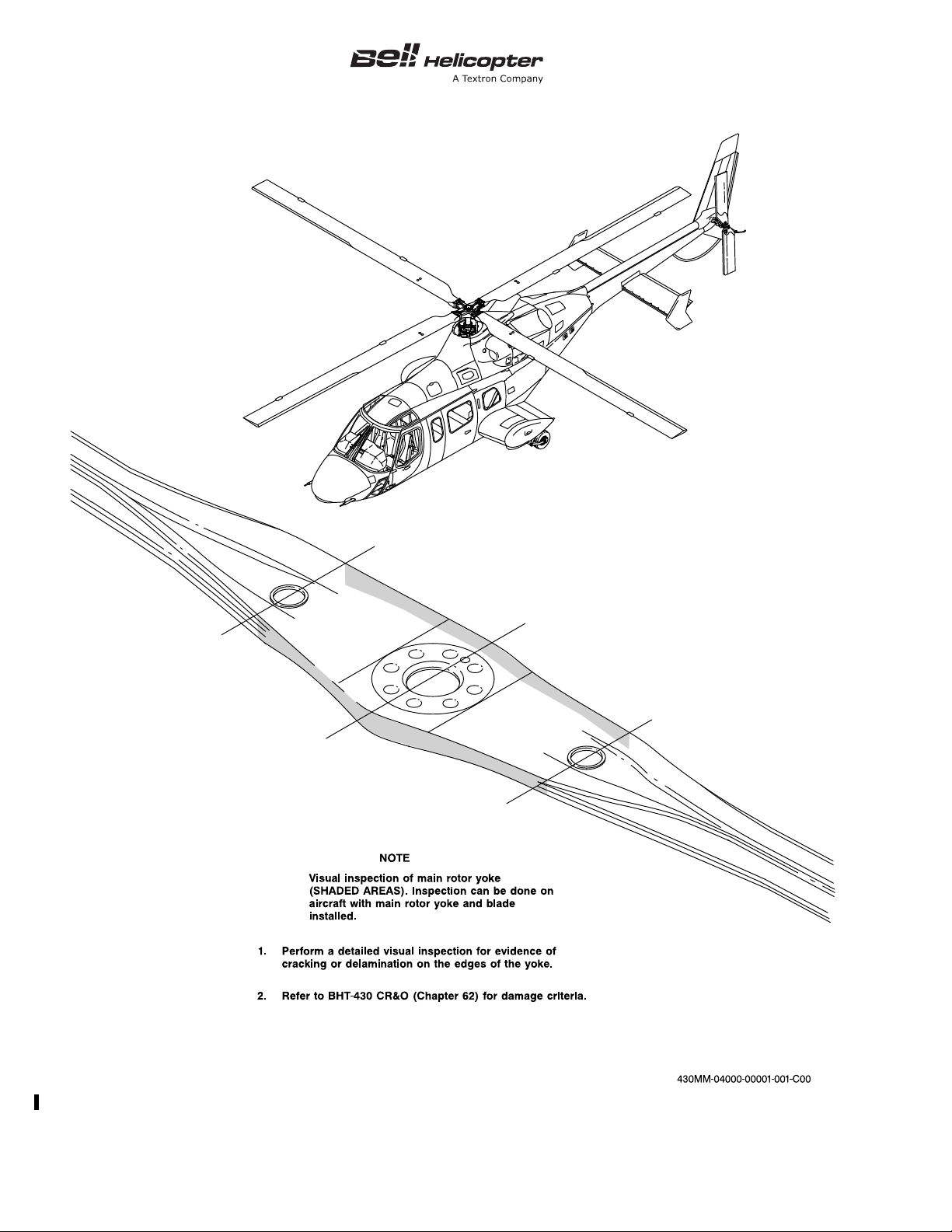
Refer to Figure 4-2 for inspection details.
Inspection applies to yokes with cracks less than 3.0 inches (76.19 mm). Inspection is limited to arm that
has crack(s) less than 3.0 inches (76.19 mm). Refer to Figure 4-1.
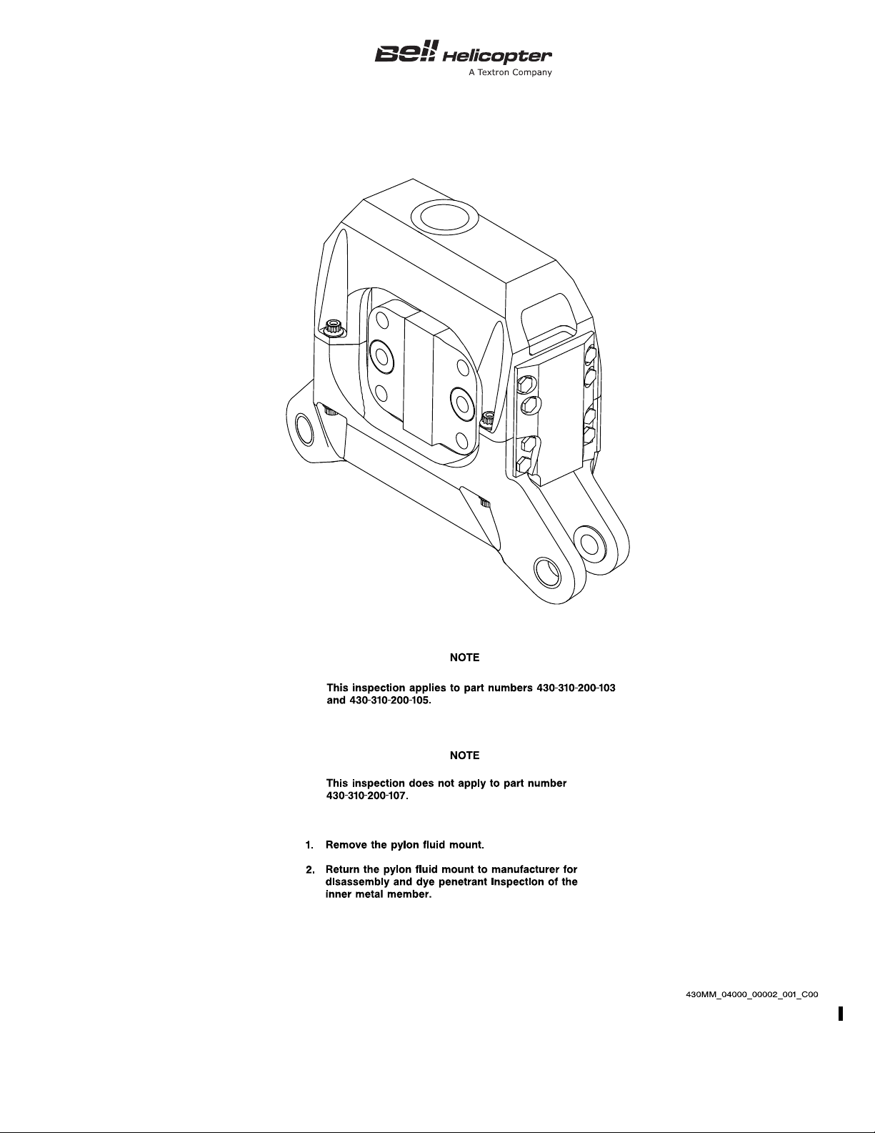
Refer to Figure 4-3 for inspection details.
This inspection does not apply to pylon fluid mount 430-310-200-107.
Refer to Figure 4-4 for inspection details.
Refer to Figure 4-5 for inspection details.
Refer to Figure 4-6 for inspection details.
4-00-00
Page 10 Rev. 19 1 NOV 2012
ECCN EAR99
Page 23
TC APPROVED BHT-430-MM-2
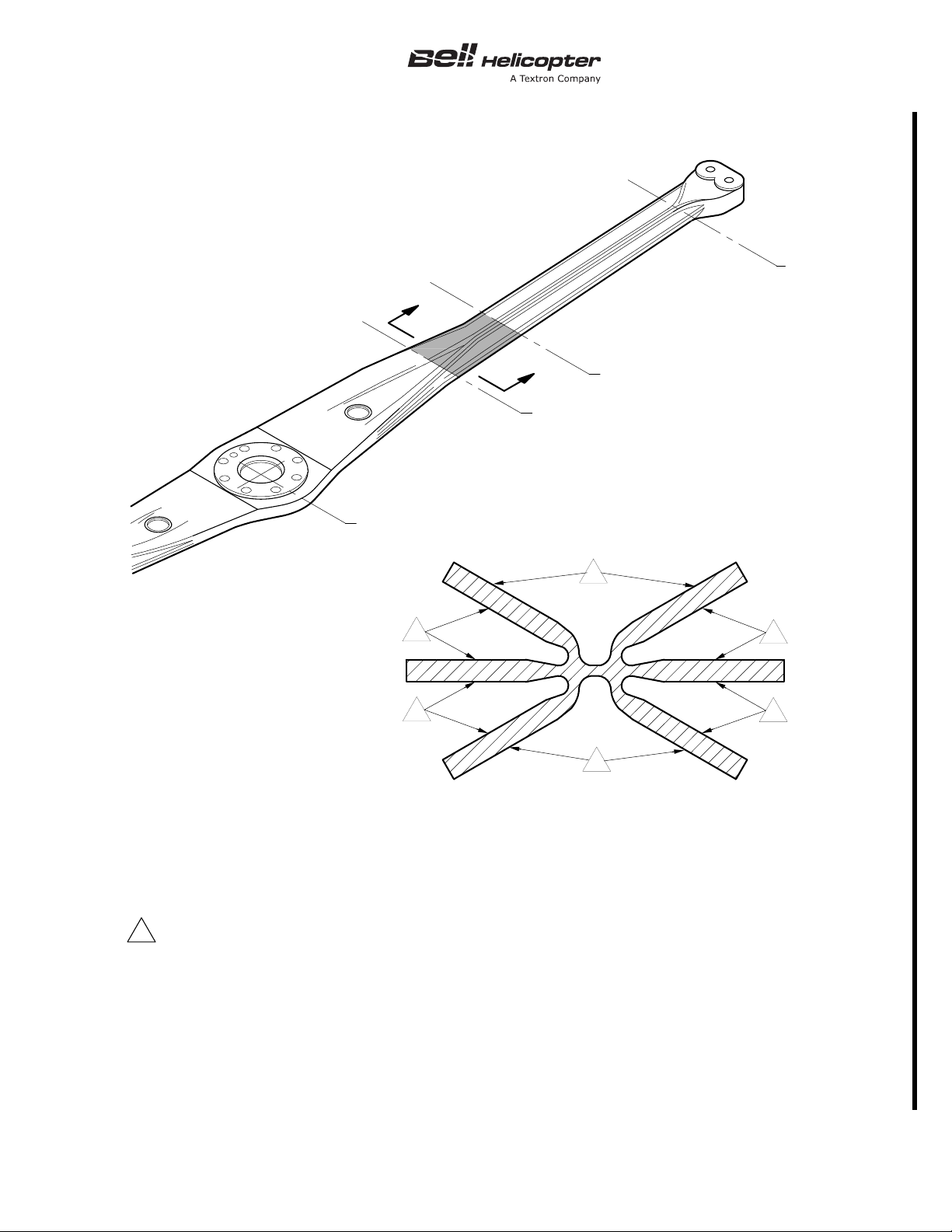
Inspect surfaces for spanwise crack damage between yoke stations 23.0 and 31.0.
Inspection applies to yokes with cracks. Inspection is limited to arm that has crack(s).
Refer to BHT-430-CR&O-2 (Chapter 62) for damage criteria.
NOTES
1
1
1
STATION 31.0
STATION 55.0
STATION 23.0
STATION 0.0
A
A
SECTION A-A
430_MM_04_0001
1
2.
3.
1
1
1
ECCN EAR99
Figure 4-1. Main Rotor Yoke — 100-Hour and 600-Hour Inspection
4-00-00
1 NOV 2012 Rev. 19 Page 11
Page 24
BHT-430-MM-2 TC APPROVED
Figure 4-2. Main Rotor Yoke Edges — Inspection
4-00-00
Page 12 Rev. 19 1 NOV 2012
ECCN EAR99
Page 25
TC APPROVED BHT-430-MM-2
ECCN EAR99
Figure 4-3. Pylon Fluid Mount — Inspection
4-00-00
1 NOV 2012 Rev. 19 Page 13
Page 26
BHT-430-MM-2 TC APPROVED
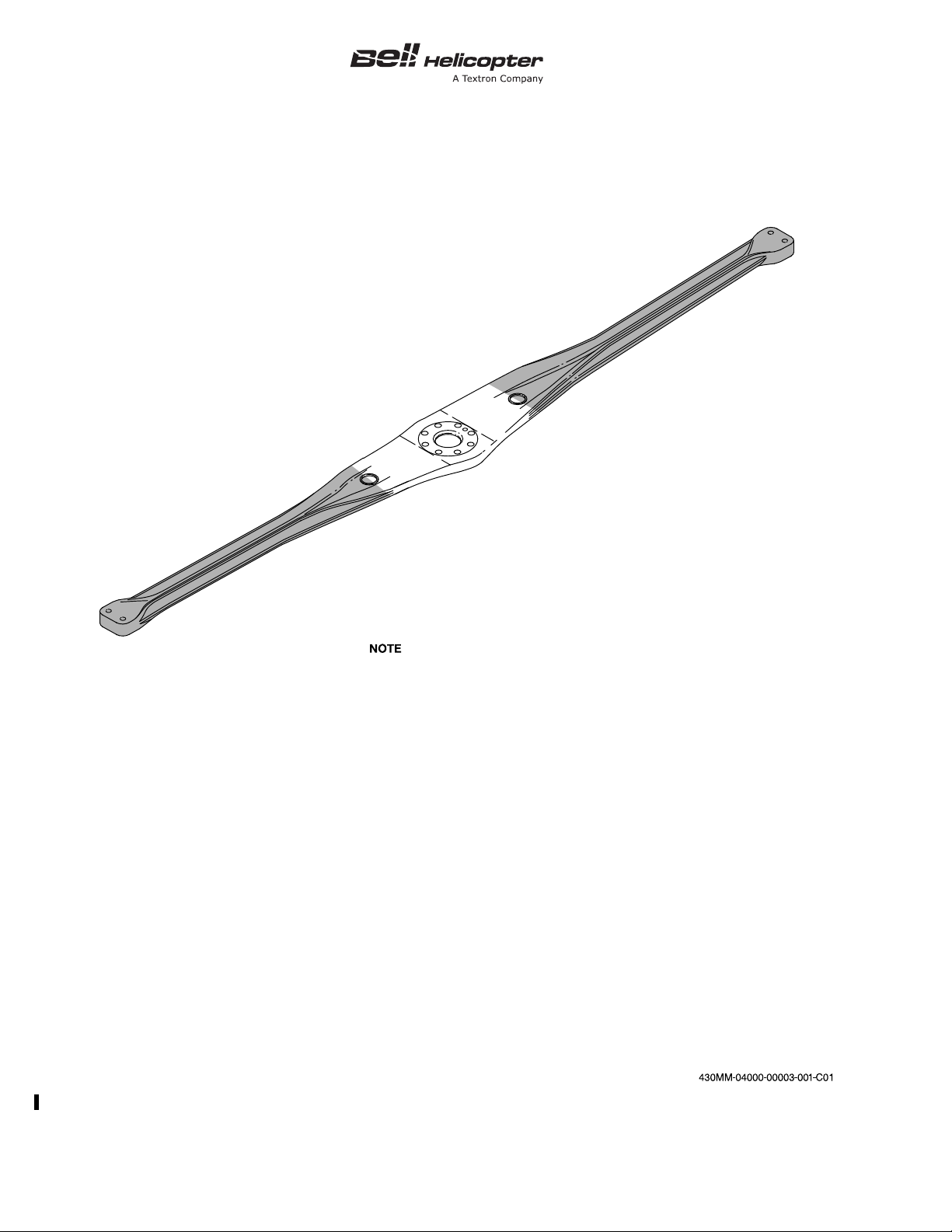
Refer to BHT-430-CR&O (Chapter 62) for
inspection and damage criteria.
1.
2.
3.
Remove main rotor yoke.
Clean main rotor yoke.
Perform a detail visual inspection of the entire
yoke for evidence of cracking, delamination
and damage. Specific attention should be
applied to the shaded areas.
Figure 4-4. Main Rotor Yoke — 2500-Hour Inspection
4-00-00
Page 14 Rev. 19 1 NOV 2012
ECCN EAR99
Page 27
TC APPROVED BHT-430-MM-2
ECCN EAR99
Figure 4-5. Main Rotor Blade — Inspection
4-00-00
1 NOV 2012 Rev. 19 Page 15
Page 28
BHT-430-MM-2 TC APPROVED
Figure 4-6. Pylon Fluid Mount — Torque Shear Pad Bolt Replacement
4-00-00
Page 16 Rev. 19 1 NOV 2012
ECCN EAR99
Page 29

BHT-430-MM-2
TABLE OF CONTENTS
Paragraph Chapter/Section Page
Number Title Number Number
CHAPTER 5 — INSPECTIONS AND COMPONENT OVERHAUL SCHEDULE
INSPECTIONS
5-1 General .......................................................................................... 5-00-00 3
5-2 Items not Covered in the Inspections ....................................... 5-00-00 3
5-3 Crash Damage.......................................................................... 5-00-00 4
5-4 Types of Inspections ................................................................. 5-00-00 4
5-5 Definitions ................................................................................. 5-00-00 5
5-6 Inspection and Overhaul Tolerance ............................................... 5-00-00 5
SCHEDULED INSPECTIONS
5-7 Scheduled Inspections ................................................................... 5-00-00 7
5-8 Scheduled Airframe Inspections ............................................... 5-00-00 7
5-9 Airframe Periodic .............................................................. 5-00-00 7
5-10 Airframe Progressive ........................................................ 5-00-00 7
5-11 Inspection Program Selection ........................................... 5-00-00 7
5-12 Scheduled Component Inspection............................................ 5-00-00 8
5-13 50 Hour Inspection ........................................................................ 5-00-00 9
5-14 150 Hour Inspection ....................................................................... 5-00-00 13
5-15 600 Hour/Annual Inspection........................................................... 5-00-00 23
5-16 Progressive Inspection — Event 1................................................. 5-00-00 27
5-17 Progressive Inspection — Event 2................................................. 5-00-00 31
5-18 Progressive Inspection — Event 3................................................. 5-00-00 35
5-19 Progressive Inspection — Event 4................................................. 5-00-00 39
5-20 Progressive Inspection — Event 5................................................. 5-00-00 45
5-21 Progressive Inspection — Event 6................................................. 5-00-00 49
5-22 Progressive Inspection — Event 7................................................. 5-00-00 53
5-23 Progressive Inspection — Event 8................................................. 5-00-00 59
5-24 Progressive Inspection — Event 9................................................. 5-00-00 63
5-25 Progressive Inspection — Event 10............................................... 5-00-00 67
5-26 Progressive Inspection — Event 11............................................... 5-00-00 71
5-27 Progressive Inspection — Event 12............................................... 5-00-00 75
5-28 Every 100 Hours of Component Operation.................................... 5-00-00 79
5-29 Every 300 Hours of Component Operation.................................... 5-00-00 81
5-30 Every 600 Hours or 6 Months of Component Operation ................ 5-00-00 83
5-31 Every 600 Hours or 12 Months of Component Operation.............. 5-00-00 85
5-32 Every 600 Hours of Component Operation.................................... 5-00-00 87
5-33 Every 1200 Hours of Component Operation.................................. 5-00-00 89
5-34 Every 2500 Hours of Component Operation.................................. 5-00-00 91
5-35 Every 6 Months .............................................................................. 5-00-00 93
5-36 Every 2 Calendar Years................................................................. 5-00-00 95
5-37 Every 3 Calendar Years................................................................. 5-00-00 99
5-38 Every 5 Calendar Years................................................................. 5-00-00 101
ECCN EAR99
9 SEP 2011 Rev. 18 Page 1
5-00-00
Page 30

BHT-430-MM-2
TABLE OF CONTENTS (CONT)
Paragraph Chapter/Section Page
Number Title Number Number
FIGURES
Figure Page
Number Title Number
TABLES
Table Page
Number Title Number
SPECIAL INSPECTIONS
5-39 Special Inspections ........................................................................ 5-00-00 103
5-40 After Every Main Rotor Blade Removal ......................................... 5-00-00 105
5-41 After 1 to 5 Hours of Operation Following Each Installation .......... 5-00-00 107
5-42 After 5 to 10 Hours of Operation Following Each Installation ........ 5-00-00 109
5-43 After 25 Hours of Operation Following Each Installation ............... 5-00-00 111
5-44 After 100 Hours of Operation Following Each Installation ............. 5-00-00 113
CONDITIONAL INSPECTIONS
5-45 Conditional Inspections .................................................................. 5-00-00 115
5-46 Hard Landing ................................................................................. 5-00-00 117
5-47 Sudden Stoppage — Power ON or OFF........................................ 5-00-00 125
5-48 Overtorque ..................................................................................... 5-00-00 133
5-49 One Engine Inoperative (OEI)........................................................ 5-00-00 139
5-50 Lightning Strike .............................................................................. 5-00-00 143
5-51 Overspeed ..................................................................................... 5-00-00 147
5-52 Compressor Stall or Surge............................................................. 5-00-00 149
COMPONENT OVERHAUL SCHEDULE
5-53 Component Overhaul Schedule..................................................... 5-00-00 153
5-1 Maintenance Zones ............................................................................................ 6
5-1 Progressive Inspection Events............................................................................ 7
5-2 Component Overhaul Schedule.......................................................................... 153
5-3 Tail Rotor Driveshaft Hanger Bearing Assembly ................................................ 156
5-00-00
Page 2 Rev. 18 9 SEP 2011
ECCN EAR99
Page 31

INSPECTIONS
WARNING
NOTE
BHT-430-MM-2
5-1. GENERAL
This chapter contains the time limit interval and
requirements for the Scheduled, Special, and
Conditional Inspections and a Component Overhaul
Schedule.
FAILURE TO CORRECT CONDITIONS
SUCH AS, BUT NOT LIMITED TO,
CORROSION, EROSION, MECHANICAL
DAMAGE, OR OBVIOUS WEAR FOUND
DURING A SCHEDULED INSPECTION
COULD SERIOUSLY AFFECT THE
AIRWORTHINESS OF THE HELICOPTER.
The inspection intervals given in this chapter are the
maximum permitted. Do not exceed these intervals.
The owner/operator are responsible for increasing the
scope and frequency of the inspections as necessary.
Make sure the helicopter is operated safely during all
unusual local changes, such as environmental
conditions, helicopter use, etc. You can request
changes to the requirements in this chapter through
the local aviation authority.
The inspection intervals and the Component Overhaul
Schedule given in this chapter are applicable only to
Bell Helicopter Textron approved parts.
The time period given for overhaul of a
component (or the failure to give a time
period for the overhaul of a component)
does not constitute a warranty of any kind.
The only warranty applicable to the
helicopter or any component is the
warranty included in the Purchase
Agreement for the helicopter or the
component.
The Time Between Overhaul (TBO) and the inspection
periods are determined through experience, tests,
Lead-The-Fleet (LTF), or any other special programs
and the judgement of Bell Helicopter Textron
engineers. They are subject to change only by Bell
Helicopter Textron or an approved airworthiness
authority.
Changes to TBO will be introduced by either revision
to the Maintenance Manual Chapter 5 or a Technical
Bulletin.
Every calendar and hourly inspection is a thorough
visual inspection to determine the airworthiness of the
helicopter and components. Qualified persons must do
the inspections in accordance with quality standard
aircraft practices and the applicable maintenance
manuals. Bell Helicopter Textron considers that it is
mandatory to obey all the applicable Alert Service
Bulletins (ASB) and Airworthiness Directives (AD).
Component operating time records are necessary for
components that have scheduled maintenance
procedures that are different from those of the
airframe. It is the owner/operator’s responsibility to
keep Historical Service Records for the applicable
components and do the necessary maintenance
procedures.
Before each inspection, remove or open the
necessary cowlings, fairings, inspection doors, and
panels.
5-2. ITEMS NOT COVERED IN THE
INSPECTIONS
This manual does not include specific inspection
intervals for some components such as the compass
calibration and the pitot static test. These specific
inspection intervals are given by your government
regulatory authority. Refer to their requirements for
these specific inspections.
The owner/operator of the helicopter is responsible for
the maintenance done on the helicopter. It is the
owner/operator’s responsibility to:
1. Establish and maintain log books, and review
them for discrepancies.
2. Make sure that the Alert Service Bulletins (ASB),
the Airworthiness Directives (AD), and the special
inspections are done when they are required to be
done.
ECCN EAR99
5-00-00
9 SEP 2011 Rev. 18 Page 3
Page 32

BHT-430-MM-2
3. Make sure that the scheduled inspections, the
special inspections, and the required tests for all of the
installed kits are complied with.
4. Make sure all parts and components for which
Historical Service Records are required have
documented traceability to their original installation in
the helicopter.
5. Make sure that all limited life parts that have
completed their published operating limits are
replaced.
6. Make sure that all of the components that have
completed their published overhaul periods are
overhauled.
7. Make sure that all of the maintenance that is
done on the helicopter is done by an approved
maintenance organization.
The maintenance organization/person doing the
maintenance is responsible for the quality of the
maintenance done.
The owner/operator may choose to ask the
maintenance organization/person doing the
maintenance to perform the tasks listed by prior
arrangement through a separate formal agreement.
5-3. CRASH DAMAGE
Because of the many possible combinations that can
result from crash damage, it is not possible to include
the specified repair schemes in this category. The
helicopter mechanic must make an analysis of the
crash damage for each situation. Do the repairs in
accordance with the degree of damage to the specific
part and the applicable repair instructions in this
manual. Call Bell Helicopter Textron Product Support
Engineering with your analysis of the crash damage.
5-4. TYPES OF INSPECTIONS
1. The maintenance procedures may include
scheduled inspections, special inspections, conditional
inspections, component interim inspections, and
component overhaul inspections.
a. Scheduled inspections must occur at specified
operating intervals. The intervals may be in operating
time (hours), cycles, torque events (R.I.N.), calendar
(days, months, years) or other assigned units. This
makes sure that the helicopter is airworthy.
b. Special inspections are of a temporary nature
or of a special interval not consistent with the
scheduled inspections.
c. Conditional inspections do not occur at a
specified time. They are based on known or suspected
unusual events, known or suspected malfunctions or
defects.
d. An interim inspection occurs between
overhauls.
e. The component overhaul schedule gives the
elapsed operating time at which a component must be
removed, disassembled, examined for condition, and
overhauled in accordance with data approved by Bell
Helicopter Textron.
2. Lubrication and service requirements are in
addition to those stated in this chapter (Chapter 12).
3. For corrosion control, refer to the Corrosion
Control Guide (CSSD-PSE-87-001) and the
BHT-ALL-SPM.
4. For the 250-C40B engine, refer to the
Rolls-Royce Operations and Maintenance Manual for
the scheduled inspection, special inspection,
conditional inspection, and component overhaul
schedule.
5. For the common Bell Helicopter Textron approved
optional equipment that is integrated into this
maintenance manual, refer to this chapter for the
scheduled inspection, conditional inspection,
component interim inspection, and component
overhaul inspection.
6. For all other Bell Helicopter Textron approved
equipment, refer to the applicable Supplement in
Chapter 99 of this manual for the scheduled
inspection, special inspection, conditional inspection,
component interim inspection, and component
overhaul inspection.
7. For the inspection requirement for optional
equipment approved under Supplement Type
Approval/Certificate (STA/STC), refer to the applicable
STA/STC documentation. Maintenance and inspection
5-00-00
Page 4 Rev. 18 9 SEP 2011
ECCN EAR99
Page 33

BHT-430-MM-2
WARNING
of these items is the responsibility of the owner/
operator.
5-5. DEFINITIONS
• Examine — Look carefully to find the condition of
the component. Find how that condition relates to
a specific standard.
• Condition — The state of an item as related to a
known standard.
• Security — The presence of attaching parts that
are properly tightened or appear to be, and the
presence of properly installed (as required)
locking devices such as lockwire, cotter pins, or
other.
• Standard — A specific rule or measurement that
you use to find the condition of a component.
• Damage — Physical deterioration of a
component.
• Discard — Reject a component that has damage
that cannot be repaired. To permanently remove
from service.
• Inspection — A procedure that includes checking,
inspecting, and examining a system or
component.
• Non scheduled inspection — An inspection that
has not been scheduled.
• Periodic inspection — An inspection which is
repeated at equal time intervals.
• Progressive inspection — A scheduled inspection
that is divided into smaller segments. This makes
the best use of the time and resources available.
• Maintenance — The servicing and/or the repair of
a helicopter, a system, or a component that keeps
it serviceable.
Records or in the helicopter logs. The operating
time is defined as:
– Time in service (flight time) — The measured
time which starts the moment the helicopter
leaves the ground until it touches the ground
at the next point of landing. The time when the
helicopter is on the ground, with the engine
and the rotor turning, is not included.
– Calendar time — The elapsed time which
starts on the day the inspection is completed,
the component is installed, or the rotor turned
for the first time and ends on the last day of
the month that the time limit expires. Calendar
time is continuous. Calendar time does not
stop when you remove a component, put the
helicopter in storage, etc.
• Maintenance zone — A specified area of the
helicopter which may contain more than one
system or more than one group of related
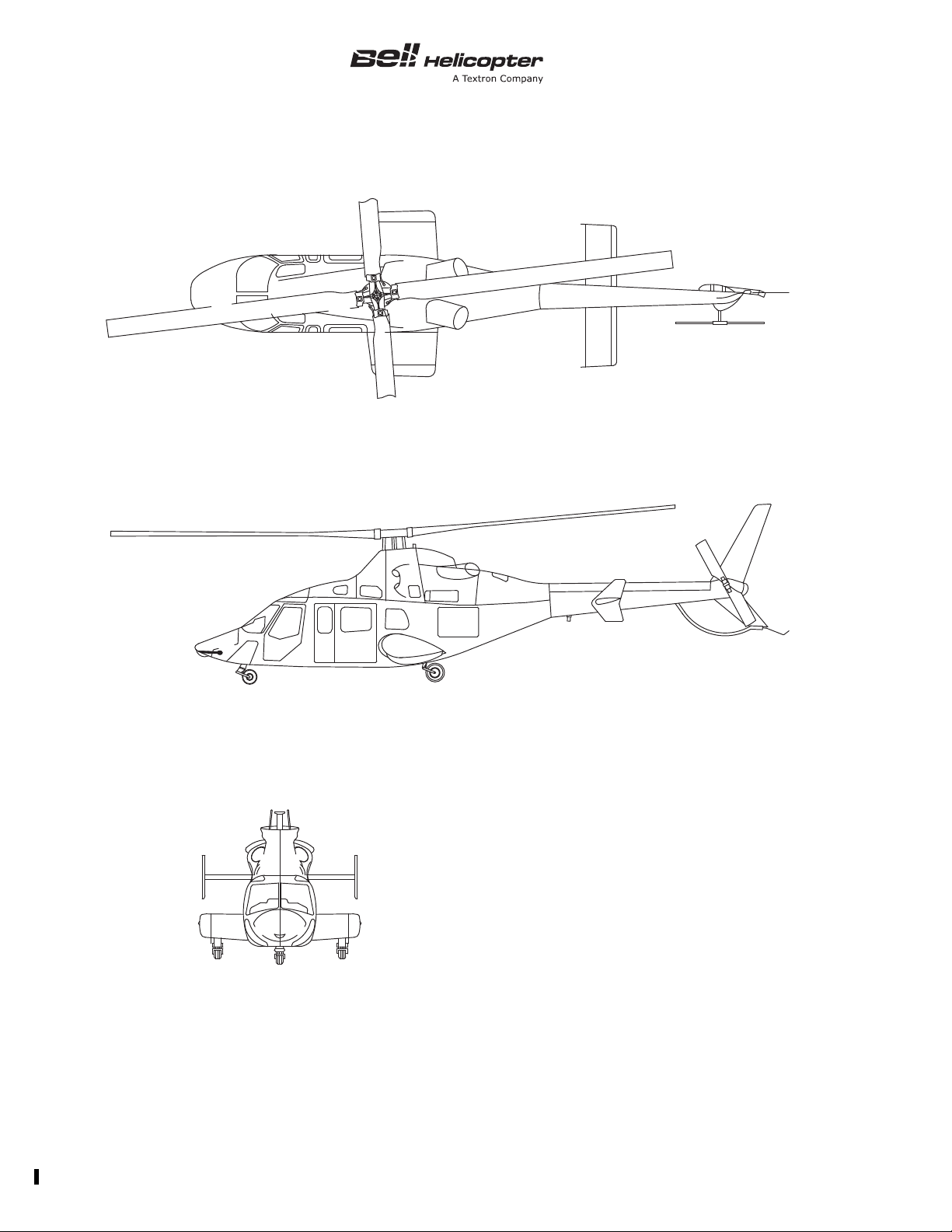
components. Maintenance zones (Figure 5-1) are
used when you do a progressive inspection.
• Lead-The-Fleet (LTF) Program — This is a
program designed to validate the performance of
an approved product improvement or a change to
a maintenance interval. The engineering aspects
of this change are approved. The program is
closely monitored by Bell Helicopter Textron in an
operational environment with selected operators.
• Special Programs — These are approved
programs that may be initiated under certain
special conditions to meet specific requirements.
These programs will be clearly defined through a
plan and the engineering and maintenance
aspects will be approved by the regulatory
authorities.
5-6. INSPECTION AND OVERHAUL
TOLERANCE
• Preventive maintenance — To do small
maintenance action(s) on a regular basis to
prevent non scheduled maintenance.
• Operating time — Actual flight or calendar time
that must be recorded in the Historical Service
ECCN EAR99
DO NOT APPLY THESE TOLERANCES
TO PARTS WITH A LIMITED
AIRWORTHINESS LIFE (CHAPTER 4).
5-00-00
9 SEP 2011 Rev. 18 Page 5
Page 34
BHT-430-MM-2
E1
E2
F1
F2
F3
F4
F5
F6
R1
R2
T1
T2
W1
W2
430_MM_05_0001
Left engine
Right engine
Left forward fuselage
Right forward fuselage
Left aft fuselage
Right aft fuselage
Left pylon
Right pylon
Main rotor
Tail rotor
Left tailboom
Right tailboom
Left wing
Right wing
F2
F1
F1
F4
F3
F3
F5
F5
F6
F5F6
W1
W1
W2
F2
F1
W1W2
E2
E1
E1
T1
T1
T2
R2
R1
5-00-00
Page 6 Rev. 15 26 JAN 2007
Figure 5-1. Maintenance Zones
Page 35

The Bell Helicopter Textron approved tolerance for
NOTE
scheduled inspections, special inspections, interim
inspections, and overhaul intervals, unless otherwise
stated, is 10% or up to a maximum of 100 hours
operating time/30 days calendar time, whichever is
less. The tolerances are established for maintenance
scheduling convenience only.
Scheduled inspections, special inspections, interim
inspections, or overhaul intervals required beyond the
stated tolerances must be approved by Product
Support Engineering.
BHT-430-MM-2
The following is only applicable for those
operators whose governing aviation
authority requires to specifically approve
the inspection and overhaul tolerance.
If approval of the inspection and overhaul tolerance is
required by the applicable governing aviation authority,
this is the responsibility of the owner/operator.
Refer to the Rolls-Royce 250-C40B Operation and
Maintenance Manual for inspection and overhaul
tolerances.
ECCN EAR99
5-00-00
9 SEP 2011 Rev. 18 Page 6A/6B
Page 36

Page 37

SCHEDULED INSPECTIONS
BHT-430-MM-2
5-7. SCHEDULED INSPECTIONS
Scheduled inspections include airframe and
component inspections. The scheduled airframe
inspection intervals are based on the airframe
operating time. The scheduled component inspection
intervals are based on the component operating time.
5-8. SCHEDULED AIRFRAME INSPECTIONS
Bell Helicopter Textron developed two scheduled
airframe inspection programs to give flexibility for
maximum helicopter use. An operator can choose one
of the Bell programs or design their own program. The
selection of an alternative inspection program and its
approval by the governing civil aviation authority is the
responsibility of the owner/operator.
5-9. Airframe Periodic
Do the inspections at intervals of 50 hours, 150 hours
and 600 hours. You must do a minimum of one
complete 50 hour, 150 hour and 600 hour inspection
within 12 months.
Table 5-1. Progressive Inspection Events
AIRFRAME
HOURS
50 1
100 2
150 3
200 4
250 5
300 6
350 7
400 8
450 9
500 10
550 11
600 12
EVENT
NUMBER
5-10. Airframe Progressive
The requirements of the airframe periodic 50 hour, 150
hour and 600 hour inspections are combined in 12
separate events of similar workload, and are done at
50 hour intervals. You must do the events in the
sequence shown in Ta b le 5 -1 . After you complete
event 12, the progressive cycle begins again with
event 1. You must do a minimum of one complete
cycle (12 events) within 12 months.
5-11. Inspection Program Selection
You must establish the airframe periodic or the
airframe progressive program to maintain the
helicopter from new. To change between the periodic
and progressive programs you must first do the 50
hour, 150 hour and 600 hour inspections. The owner/
operator is responsible to not exceed the time interval
of any scheduled airframe inspection procedure.
ECCN EAR99
5-00-00
9 SEP 2011 Rev. 18 Page 7
Page 38

BHT-430-MM-2
5-12. SCHEDULED COMPONENT INSPECTION
Scheduled component inspections have been
established for those items to be inspected at intervals
other than those established for aircraft periodic
inspections. Do the scheduled component inspections
at every interval that follows.
• 100 hours
• 300 hours
• 600 hours or 6 months
• 600 hours or 12 months
• 600 hours
• 1200 hours
• 2500 hours
• 6 months
• 2 years
• 3 years
• 5 years
5-00-00
Page 8 Rev. 18 9 SEP 2011
ECCN EAR99
Page 39
5-13. 50 HOUR INSPECTION
_
_
_
_
_
_
BHT-430-MM-2
SCHEDULED INSPECTIONS
DATA REFERENCE INSPECTION TASK DESCRIPTION
DATE: __________________W.O. ____________________
FACILITY: _________________________________________
HELICOPTER S/N: __________________________________
REGISTRY NO.: ____________________________________
TOTAL TIME:______________________________________
SIGNATURE:_______________________________________
To be performed every 50 hours of operating time or a minimum
of once every 12 months, whichever comes first.
GENERAL:
1. Examine all of the electrical wiring open to view for worn or
frayed cables. make sure there are no loose or broken clamps
or fasteners.
INITIAL
MECH OTHER
NOTE
It is recommended to interrogate the IIDS
maintenance pages on both IIDS screens and the
engines ECU on a weekly basis (mandatory at 50
hour inspection) for any recorded fault codes or
exceedances.
2. Interrogate the Integrated Instrument Display System
(IIDS) for any maintenance advisory flag, fault codes or
exceedance occurrences and do the necessary corrective
action. Also interrogate the ECU of both engines using
EMC-35A (MT 35) program for any FADEC fault code or
exceedances. Following maintenance action, clear ALL
recorded fault codes and any exceedances that is not
cumulative from both IIDS screens and from the engines ECU
to prevent any future confusion. Logged exceedances not
requiring maintenance action should also be cleared from IIDS
and ECU(s).
9 JAN 2008 Rev. 16 Page 9
5-00-00
Page 40
BHT-430-MM-2
SCHEDULED INSPECTIONS
5-13. 50 HOUR INSPECTION (CONT)
DATA REFERENCE INSPECTION TASK DESCRIPTION
Rolls-Royce
250-C40B Operation
and Maintenance
Manual, Publication
CSP 21000
Chapter 12 4. Lubricate the helicopter as necessary.
Chapter 53 1. Examine the outside of the airframe and the tailboom
Chapter 32 2. Examine the landing gear forward crosstube, skid tubes
3. Do the applicable engine inspection.
DETAIL:
assembly for cracks and other damage. Examine the bottom of
the fuselage and wings for fuel leaks.
and skid shoes for damage and to make sure it is correctly
attached.
3. Examine the landing gear aft cross tube, support beam,
pivot bolt and wear strips for damage and to make sure it is
correctly attached.
INITIAL
MECH OTHER
Chapter 32 4. If retractable landing gear is installed, examine the nose
landing gear doors for damage and to make sure the linkage is
correctly attached. Examine the doors for cracks in the skin near
the hinges. (F1/F2)
Chapter 32 and
BHT-430-CR&O-V.1
Chapter 32 and
BHT-430-CR&O-V.1
5. If retractable landing gear is installed, examine the nose
landing gear for damage and the extend-retract and downlock
actuators for leaks. Examine the tire for correct pressure and
wear. Examine the wheel for cracks and to make sure it is
serviceable. (F1/F2)
6. If retractable landing gear is installed, examine the main
landing gear for damage and the extend-retract and downlock
actuators for leaks. Examine the brake assemblies for hydraulic
leaks and more than allowable lining wear. Examine the brake
discs and torque keys for damage. Examine the tires for correct
pressure and wear. Examine the wheels for cracks and to make
sure they are serviceable. (W1/W2)
5-00-00
Page 10 Rev. 16 9 JAN 2008
Page 41
SCHEDULED INSPECTIONS
5-13. 50 HOUR INSPECTION (CONT)
BHT-430-MM-2
DATA REFERENCE INSPECTION TASK DESCRIPTION
7. Examine the battery for cracks, electrolyte leaks and
corrosion. (F4)
Chapter 29 and
BHT-430-CR&O-4
Chapter 62 9. Examine the upper universal bearings on the main rotor
Chapter 29 10. Examine the tail rotor control actuator for worn bearings.
Chapter 64 and
BHT-ALL-SPM
8. Examine the cyclic and collective control actuators for worn
bearings. Make sure they are correctly attached to the actuator
support. Examine the actuator pistons for score marks, pits,
wear and hydraulic leaks more than the allowable limits. (R1)
pitch links for wear and looseness between the inner races and
the housing. Examine the lower rod ends for axial or radial
looseness. (R1)
Make sure it is correctly attached. Examine the actuator piston
for score marks, pits, wear and hydraulic leaks more than the
allowable limits. (F3/F4)
11. Examine the tail rotor pitch links for worn bearings and
freedom of operation. (R2)
INITIAL
MECH OTHER
Chapter 62 and
Chapter 64
NOTE
Clean the main and tail rotor blades more frequently
if operating in a corrosive environment or in extreme
environmental conditions.
12. Clean the main and tail rotor blades. Make sure the drain
hole located on the lower surface of the main rotor blade,
outboard of the attachment bolts, is clean. Inspect the main
rotor blade(s) cuff for water and/or debris accumulation. (R1/R2)
13. Inspect the main rotor blade leading edge for erosion.
Inspect the condition of the E-Nickel cap. Cracks in the cap are
acceptable provided there are no adjacent voids and
delamination.
14. When the blades are dry, apply WD-40 to the top and
bottom surfaces of the tail rotor blades. (R2)
15. Examine the main rotor adapter assemblies for evidence of
contact with the upper stop assembly plug. (R1)
5-00-00
9 JAN 2008 Rev. 16 Page 11
Page 42
BHT-430-MM-2
SCHEDULED INSPECTIONS
5-13. 50 HOUR INSPECTION (CONT)
DATA REFERENCE INSPECTION TASK DESCRIPTION
16. Examine the main rotor adapter assemblies for evidence of
contact between the adapter pads and the yoke assembly. (R1)
17. If evidence of contact is found in step 15 and step 16, do
the steps that follow: (R1)
Chapter 62 a. Remove the main rotor blades and examine damage.
Chapter 62 b. Examine the yoke assembly for cracks and
delamination.
Chapter 62 c. Examine the adapters and upper stop assemblies for
damage and deformations.
Chapter 62 d. Examine the lead lag dampers for delamination and
general condition.
e. Prior to main rotor blade installation, remove contact
evidence from up-stop end plug and replace adapter lead lag
pads as required.
INITIAL
MECH OTHER
5-00-00
Page 12 Rev. 16 9 JAN 2008
Page 43
5-14. 150 HOUR INSPECTION
_
_
_
_
_
_
BHT-430-MM-2
SCHEDULED INSPECTIONS
DATA REFERENCE INSPECTION TASK DESCRIPTION
DATE: __________________W.O. ____________________
FACILITY: _________________________________________
HELICOPTER S/N: __________________________________
REGISTRY NO.: ____________________________________
TOTAL TIME:______________________________________
SIGNATURE:_______________________________________
To be performed every 150 hours of operating time or a
minimum of once every 12 months, whichever comes first.
GENERAL:
1. Examine all of the electrical wiring open to view for worn or
frayed cables. Make sure there are no loose or broken clamps
or fasteners.
INITIAL
MECH OTHER
Rolls-Royce
250-C40B Operation
and Maintenance
Manual, Publication
CSP 21000
Chapter 12 3. Lubricate the helicopter as necessary.
Chapter 25 1. Examine the seat cushions and seat backs for tears and
Chapter 25 2. Examine the seat assemblies to make sure they are
Chapter 25 3. Examine the crew seat attenuation indicators. (F1/F2)
2. Do the applicable engine inspection.
DETAIL:
deterioration. Make sure they are correctly attached. (F1/F2/F3/
F4)
correctly attached to airframe structure. (F1/F2/F3/F4)
26 JAN 2007 Rev. 15 Page 13
5-00-00
Page 44
BHT-430-MM-2
SCHEDULED INSPECTIONS
5-14. 150 HOUR INSPECTION (CONT)
DATA REFERENCE INSPECTION TASK DESCRIPTION
Chapter 25 4. Examine the safety belts and shoulder harnesses for
deterioration. Make sure they are correctly attached to the
airframe structure. (F1/F2/F3/F4)
Chapter 53 5. Examine the crew doors, passenger doors and baggage
compartment doors for damage or corrosion. Examine the
positive locking mechanisms. Examine the door seals for tears
or separations. Make sure the doors are correctly attached to
the airframe structure. (F1/F2/F3/F4)
Chapter 26 6. Examine the cabin fire extinguisher for damage or
corrosion. Examine the operation of the quick opening clamp.
Make sure the fire extinguisher is fully charged. (F1/F2)
Chapter 11 and
BHT-430-FM-1
Chapter 53 8. Examine the condition of the electrical and avionics
7. Examine the placards and instrument panel decals. Make
sure all of the instrument markings are clear and legible. (F1/F2)
components in the nose compartment. Make sure they are
correctly installed. Examine the electrical harnesses and cables
for frayed wires and loose or broken clamps and fasteners.
INITIAL
MECH OTHER
9. Examine the nose compartment door for damage. Make
sure it latches correctly. (F1/F2)
Chapter 95 10. Examine the pitot tubes. Make sure they are correctly
attached. (F1/F2)
Chapter 67 and
BHT-ALL-SPM
11. Examine the cyclic and collective shaft assemblies and
control tubes installed on the roof for loose bearings, wear,
corrosion or mechanical damage. Make sure they are correctly
attached. (F5/F6)
5-00-00
Page 14 Rev. 15 26 JAN 2007
Page 45
SCHEDULED INSPECTIONS
5-14. 150 HOUR INSPECTION (CONT)
BHT-430-MM-2
DATA REFERENCE INSPECTION TASK DESCRIPTION
NOTE
Examine inspection window(s) and sight glass(es)
for cracking and discoloration. If either of these
conditions are present the part must be removed and
replaced prior to returning helicopter for service.
Chapter 29 12. Examine the hydraulic lines for leaks. Examine the color
and level of the fluid in the PC-1 system and PC-2 system
reservoirs. Examine the module pressure and return filters for
impending bypass indication. Make sure that the flexible hoses
are in good condition and do not show signs of chafing. (F5/F6)
13. Examine the collective lever idler link attachment points
that connect the swashplate support assembly to the collective
lever, for wear, corrosion and damage.
BHT-430-CR&O-2 14. Inspect hydraulic actuator support attaching nuts for proper
torque. (R1)
Chapter 62 15. Examine the cyclic and collective control levers, collective
idler link, swashplate assembly, drive hub assembly, drive link
assembly and idler link assembly for interference, looseness,
mechanical damage or corrosion. Make sure they are correctly
attached. (R1)
INITIAL
MECH OTHER
Chapter 4
16. Examine the main rotor hub for damage and correct
installation. Examine the upper and lower stops, pitch links and
the hub to mast attach bolts for corrosion and damage. Make
sure they are correctly attached. (R1)
NOTE
Step 17 is an airworthiness inspection limitation.
17. Examine the main rotor yoke center section (center to
station 15) as follows: (R1)
a. Clean the yoke center sections.
b. Do a careful visual inspection of the yoke center
sections for delamination and damage.
5-00-00
26 JAN 2007 Rev. 15 Page 15
Page 46
BHT-430-MM-2
SCHEDULED INSPECTIONS
5-14. 150 HOUR INSPECTION (CONT)
DATA REFERENCE INSPECTION TASK DESCRIPTION
c. If any defects are found, contact Bell Helicopter Product
Support Engineering for instructions.
Chapter 62 18. Examine the damper blade sets and the shear restraints
elastomer for delamination, wear (crumbling) or damage.
Examine the fluidlastic dampers and surrounding area for signs
of leakage. Verify that the gold pin in each pressure indicator
extends above the black sleeve or the bottom of the metal cap
plastic window. Examine the adapter assemblies and pitch
horns for corrosion and damage. Make sure they are correctly
attached. (R1)
Chapter 62 19. Examine the main rotor blades for damage. Make sure
they are clean. Examine the product weight attachment screws
for correct installation and hole elongation. (R1)
NOTE
Examine inspection window(s) and sight glass(es)
for cracking and discoloration. If either of these
conditions are present the part must be removed and
replaced prior to returning helicopter for service.
INITIAL
MECH OTHER
Chapter 63 20. Examine the transmission for correct fluid level and leaks.
(F5/F6)
Chapter 63 and
Chapter 96
Chapter 63 22. Examine the main driveshaft over-temperature indicators
Chapter 65 and
BHT-430-CR&O-3
Chapter 63 24. Examine the rotor brake system for leaks. Examine the
5-00-00
Page 16 Rev. 15 26 JAN 2007
21. Remove the transmission chip detectors. Examine and
clean the chip detectors. Install the chip detectors. Perform an
operational check of each chip detector.
on the transmission and engine end driveshaft couplings for
discoloration. Examine the driveshaft couplings and surrounding
area for slung grease. (R1)
23. Examine the tail rotor driveshaft coupling over-temperature
indicators for discoloration. Examine the driveshaft coupling and
surrounding area for slung grease. (R1)
level and color of the fluid in the reservoir. Replace the brake
linings if they are worn more than the acceptable limits. Make
sure the brake linings are correctly attached. Examine the brake
disc for damage. (F3/F4/F5/F6)
Page 47
SCHEDULED INSPECTIONS
5-14. 150 HOUR INSPECTION (CONT)
BHT-430-MM-2
DATA REFERENCE INSPECTION TASK DESCRIPTION
NOTE
Examine inspection window(s) and sight glass(es)
for cracking and discoloration. If either of these
conditions are present the part must be removed and
replaced prior to returning helicopter for service.
Chapter 12 and
Chapter 79
Chapter 63 26. Examine the left and right pylon fluid mount assemblies for
25. Examine the left and right engine oil tanks for correct fluid
level and leaks. Examine all oil lines for leaks. (F5/F6)
NOTE
Examine inspection window(s) and sight glass(es)
for cracking and discoloration. If either of these
conditions are present the part must be removed and
replaced prior to returning helicopter for service.
corrosion, damage and correct fluid level indication. Make sure
they are correctly attached. (F5/F6)
INITIAL
MECH OTHER
Chapter 63 and
BHT-430-CR&O-2
Chapter 63 28. Examine the left longitudinal restraint spring and support
Chapter 63 29. Examine the right longitudinal restraint spring and the
27. Examine the upper and lower lift link rod end bearings for
serviceability. (F5/F6)
for damage. Make sure they are correctly attached. (F5)
lateral restraint spring and support for damage. Make sure they
are correctly attached. (F6)
CAUTION
THE INGESTION OF BROKEN INLET SCREEN
SEGMENTS CAN CAUSE FOREIGN OBJECT
DAMAGE TO THE ENGINE COMPRESSOR
SECTION.
Chapter 71 30. If installed, examine both of the engine inlet screens for
damage. (F5/F6)
5-00-00
26 JAN 2007 Rev. 15 Page 17
Page 48
BHT-430-MM-2
SCHEDULED INSPECTIONS
5-14. 150 HOUR INSPECTION (CONT)
DATA REFERENCE INSPECTION TASK DESCRIPTION
Chapter 71 31. Examine all of the firewalls and fire shields for cracks,
distortion, loose or missing rivets, broken spot welds and
deterioration of the seals and sealant. (E1/E2)
Chapter 71 32. Examine the left engine mounts and accessories for
damage. Make sure they are correctly attached. (E1)
Chapter 71 33. Examine the left power plant area for fuel or oil leaks.
Examine the wire harness and the flexible and rigid fuel and oil
lines for wear, chafing and damage. Make sure they are
correctly attached. (E1)
Chapter 76 34. Examine the left engine power lever, fuel control box
assembly and control cable for looseness and correct range of
motion. Make sure they are correctly attached. (E1)
Chapter 63 35. Examine the left oil-cooler blower driveshaft and couplings
for damage. Make sure they are correctly attached. Examine
the discs for cracks that radiate from the bolt holes, corrosion,
wrinkles or other signs of overstress. (E1)
INITIAL
MECH OTHER
Chapter 71 and
BHT-430-CR&O-V.2
Chapter 65 37. Examine the forward tail rotor driveshaft hanger assembly
Chapter 65 38. Examine the disc assembly on the forward tail rotor
Chapter 63 and
Chapter 79
36. Examine the left oil cooler blower for blockage, cleanliness
and damage. Make sure it is correctly attached. (E1)
for cracks at the mount ears, corrosion or mechanical damage.
Make sure it is correctly attached. Examine the bearing for
discoloration caused by an overheat condition. If applied, check
grease seal to bearing outer race index mark for alignment;
marks must be within 1/8 inch (3.2 mm) of each other. Examine
bearing for any obvious wear or damage and roughness. If any
doubt exists, proceed with inspection of the bearing for
roughness with driveshaft disconnected. (E1/E2)
driveshaft hanger coupling for cracks that radiate from the bolt
holes, corrosion, wrinkles or other signs of overstress. (E1/E2)
39. Examine the transmission and engine oil coolers for
blockage and oil leaks. Make sure they are correctly attached.
(E1/E2)
5-00-00
Page 18 Rev. 15 26 JAN 2007
Page 49
SCHEDULED INSPECTIONS
5-14. 150 HOUR INSPECTION (CONT)
BHT-430-MM-2
DATA REFERENCE INSPECTION TASK DESCRIPTION
40. Remove the access panel from the aft electrical
compartment. Examine the condition of the electrical and
avionics components and make sure they are correctly
attached. Examine the electrical harnesses and cables for
frayed wires and loose or broken clamps and fasteners. (F4)
Chapter 96 41. Remove the battery. Examine the vent lines for blockage or
damage. Clean the battery area before you install a serviceable
battery. (F4)
NOTE
Examine inspection window(s) and sight glass(es)
for cracking and discoloration. If either of these
conditions are present the part must be removed and
replaced prior to returning helicopter for service.
Chapter 26 42. Examine the left and right engine fire bottles. Make sure
they show the correct pressure. (F3/F4)
Chapter 29 and
Chapter 67
43. Remove the access panel from the bottom of the aft
fuselage. Examine the bellcrank and directional control
hydraulic actuator supports for corrosion and mechanical
damage. Examine the actuator for hydraulic leaks and worn
bearings. Make sure it is correctly attached. (F4)
INITIAL
MECH OTHER
Chapter 65 44. Examine the hangar assemblies of the tail rotor driveshaft
for cracks at the mount ears, corrosion or mechanical damage.
Make sure they are correctly attached. Examine the bearings for
discoloration caused by an overheat condition. If applied, check
grease seal to bearing outer race index mark for alignment;
marks must be within 1/8 inch (3.2 mm) of each other. Examine
bearing for any obvious wear or damage and roughness. If any
doubt exists, proceed with inspection of the bearing for
roughness with driveshaft disconnected. (T1/T2)
45. Examine the tail rotor driveshaft coupling discs and the disc
at the tail rotor gearbox input quill for cracks that radiate from
the bolt holes, corrosion, wrinkles or other signs of overstress.
(T1/T2)
Chapter 53 46. Examine auxiliary fins on the horizontal stabilizer for
damage. Make sure they are correctly attached. (T1/T2)
26 JAN 2007 Rev. 15 Page 19
5-00-00
Page 50
BHT-430-MM-2
SCHEDULED INSPECTIONS
5-14. 150 HOUR INSPECTION (CONT)
DATA REFERENCE INSPECTION TASK DESCRIPTION
Chapter 53 47. Examine the top and bottom surfaces of the horizontal
stabilizer for cracks in the area adjacent to the stabilizer
support. (T1/T2)
Chapter 53 48. Examine the tail rotor guard and the tail skid for damage.
Make sure they are correctly attached. (T1/T2)
CAUTION
REFER TO CHAPTER 53, TABLE 53-1 FOR
CORRECT TORQUE.
Chapter 53 49. Examine the vertical fin assembly for damage. Make sure
the vertical fin attach bolts/nuts have the correct torque. Apply
torque in the tightening direction to the nut while restraining the
bolt head. If lowest value of specified torque range is reached
without nut movement, raise the torque to the highest value of
specified torque range. If the nut moves below the lowest value
of specified torque range proceed with 2 Year Inspection (T1/
T2)
INITIAL
MECH OTHER
Examine inspection window(s) and sight glass(es)
for cracking and discoloration. If either of these
conditions are present the part must be removed and
replaced prior to returning helicopter to service.
Chapter 12 and
Chapter 65
Chapter 65 and
Chapter 96
5-00-00
Page 20 Rev. 15 26 JAN 2007
50. Remove the tail rotor gearbox fairing and examine the tail
rotor gearbox for oil leaks and mechanical or corrosion damage.
Make sure the gearbox has the correct fluid level. Make sure the
gearbox is correctly attached. (R2)
51. Inspect tail rotor gearbox retaining nuts for proper torque.
52. Remove the tail rotor gearbox chip detector. Examine and
clean the chip detector. Install the chip detector. Perform an
operational check of the chip detector. (R2)
NOTE
Page 51
SCHEDULED INSPECTIONS
5-14. 150 HOUR INSPECTION (CONT)
BHT-430-MM-2
DATA REFERENCE INSPECTION TASK DESCRIPTION
Chapter 64 53. Inspect tail rotor pitch control assembly as follows:
a. Check for excessive radial play between the pitch
control assembly and the tail rotor gearbox output shaft due to a
worn or debonded guide bearing. Radial play in excess of 0.018
inch (0.5080 mm) is considered excessive.
b. Check for worn areas on the tail rotor gearbox output
shaft wear sleeve.
c. Check for worn or rough crosshead bearing set.
d. Check for rough or worn counterweight bellcrank
bearings.
e. Check for worn inner race in the tail rotor idler
assembly.
f. Check for unbonded bearing in the upper leg of tail rotor
input lever assembly.
INITIAL
MECH OTHER
g. Check for worn bearings in the tail rotor pitch links.
Chapter 64 54. Make sure that the tail rotor hub and blades are clean.
Examine the blades for damage. Examine the pitch change
bearings, trunnion bearings and pitch link bearings for
looseness. Make sure the pitch horns and pitch links are
correctly attached. (R2)
Chapter 64 55. Make sure that the tail rotor hub and blade assembly
retaining nut has the correct torque. (R2)
Chapter 71 and
Chapter 79
Chapter 71 57. Examine the right engine mounts and accessories for
Chapter 76 58. Examine the right engine power lever, fuel control box
56. Examine the right power plant area for fuel or oil leaks.
Examine the flexible and rigid fuel and oil lines for wear, chafing
and damage. Make sure they are correctly attached. (E2)
damage. Make sure they are correctly attached. (E2)
assembly and control cable for looseness and correct range of
motion. Make sure they are correctly attached. (E2)
5-00-00
26 JAN 2007 Rev. 15 Page 21
Page 52
BHT-430-MM-2
SCHEDULED INSPECTIONS
5-14. 150 HOUR INSPECTION (CONT)
DATA REFERENCE INSPECTION TASK DESCRIPTION
Chapter 63 59. Examine the right oil-cooler blower driveshaft and
couplings for damage. Make sure they are correctly attached.
Examine the discs for cracks that radiate from the bolt holes,
corrosion, wrinkles or other signs of overstress. (E2)
Chapter 79 and
BHT-430-CR&O-V.2
Rolls-Royce
250-C40B Operation
and Maintenance
Manual, Publication
CSP 21000
60. Examine the right oil cooler blower for blockage,
cleanliness and damage. Make sure it is correctly attached. (E2)
61. Start the helicopter (BHT-430-FM-1) and do a FADEC
manual mode check.
INITIAL
MECH OTHER
5-00-00
Page 22 Rev. 17 1 SEP 2009
ECCN EAR99
Page 53
SCHEDULED INSPECTIONS
_
_
_
_
_
_
5-15. 600 HOUR/ANNUAL INSPECTION
BHT-430-MM-2
DATA REFERENCE INSPECTION TASK DESCRIPTION
DATE: __________________W.O. ____________________
FACILITY: _________________________________________
HELICOPTER S/N: __________________________________
REGISTRY NO.: ____________________________________
TOTAL TIME:______________________________________
SIGNATURE:_______________________________________
To be performed every 600 hours of operating time or a
minimum of once every 12 months, whichever comes first.
DETAIL:
1. Examine the contents of the first aid kit. Replace any
damaged or time expired items. Replace any items with
deteriorated packaging. (F2)
INITIAL
MECH OTHER
Chapter 12 and
Chapter 67
Chapter 67 3. Measure the amount of minimum friction on the cyclic stick,
Chapter 12 4. Remove the access panels along the bottom centerline of
Chapter 67 a. Examine the directional control tubes, rod end bearings,
2. Remove the left, center and right bottom access panels
from below the crew compartment. Examine the control tubes,
links, rod end bearings, bellcranks, supports and attach bolts for
corrosion and wear. Make sure they are correctly attached.
Make sure the spring cartridges and rotary actuators are
correctly attached. (F1/F2)
collective stick and the tail rotor pedals. Adjust the minimum
friction as necessary. (F2)
the fuselage. (F3/F4)
bellcranks, supports and attach bolts for corrosion and wear.
Make sure they are correctly attached.
b. Examine the wiring bundles for chafing. Make sure they
are correctly attached with clamps. Examine all of the exposed
structure for corrosion, distortion or cracks.
26 JAN 2007 Rev. 15 Page 23
5-00-00
Page 54
BHT-430-MM-2
SCHEDULED INSPECTIONS
5-15. 600 HOUR/ANNUAL INSPECTION (CONT)
DATA REFERENCE INSPECTION TASK DESCRIPTION
Chapter 29 c. Examine the directional control actuator for leaks. Make
sure it is correctly attached.
d. Examine the FS 340.00 bulkhead structure for distortion
or cracks in the area where directional control actuator attaches.
Chapter 67 and
BHT-ALL-SPM
Chapter 76 6. Examine the engine control cables and idle stop solenoids
Chapter 25 and
Chapter 52
Chapter 52 a. Examine the bond between the window retainer and the
5. Open the access panels in the tunnel behind the pilot
station. Examine the lower and upper cyclic and collective pitch
control bellcranks for loose bearings, corrosion or mechanical
damage to the clevises. Make sure they are correctly attached
to the supports and control tube bearings. (F5/F6)
for corrosion and damage. Make sure they are correctly
attached. (F5/F6)
7. Remove the interior trim around the emergency exit
windows in the passenger doors. Examine the emergency exit
windows as follows: (F3/F4)
door frame. Replace the retainer if it is not correctly bonded to
the frame at all points except at the two lower corners.
INITIAL
MECH OTHER
b. Examine the inboard and outboard side of all of the
rubber retainers. Replace the retainers if you find any nicks or
cracks.
c. Make sure the filler strips and the pull tabs are firmly
seated in the retainer grooves.
Chapter 25 d. Install the interior trim.
Chapter 32 8. If the helicopter has retractable landing gear, examine the
landing gear as follows: (F1/F2/F3/F4)
a. Examine the nose gear centering actuator for correct
pressure.
b. Examine oleo inflation valve and check for indication of
hydraulic fluid.
Chapter 32 c. Do an operational check of the landing gear hydraulic
system.
5-00-00
Page 24 Rev. 15 26 JAN 2007
Page 55
SCHEDULED INSPECTIONS
5-15. 600 HOUR/ANNUAL INSPECTION (CONT)
BHT-430-MM-2
DATA REFERENCE INSPECTION TASK DESCRIPTION
Chapter 53 9. Inspect horizontal stabilizer center area as follows:
a. Remove upper support assembly. Save attaching
hardware.
b. Clean upper surface of stabilizer.
NOTE
Surface must be free of all dirt and residue.
c. With bright light, inspect upper surface for any cracks,
corrosion or working rivets.
d. If no cracks, corrosion or working rivets are located,
install support assembly.
e. Remove lower support assembly. Save attaching
hardware.
f. Clean lower surface of stabilizer.
INITIAL
MECH OTHER
g. With bright light, inspect lower surface for any cracks,
corrosion or working rivets.
h. If no cracks, corrosion or working rivets are located,
install support assembly.
Chapter 67 10. Remove the aft fuselage access panel. Examine the
control tube, bellcrank and support assembly for corrosion,
mechanical damage and worn bearings and clevises. Make
sure they are correctly attached. (F4)
Chapter 67 and
BHT-430-CR&O-4
Chapter 65 12. Disconnect the tail rotor driveshaft from the transmission
11. Remove the tail rotor control tube. Examine the control
tube, nylatron sleeves at the four areas where the tube contacts
the tailboom fairleads and the heat shrink at the two ends of the
control tube. (T1/T2)
and tail rotor gearbox. Examine each tail rotor driveshaft hanger
assembly as follows: (T1/T2)
a. Rotate the driveshaft by hand and feel for roughness in
the bearing.
5-00-00
26 JAN 2007 Rev. 15 Page 25
Page 56
BHT-430-MM-2
SCHEDULED INSPECTIONS
5-15. 600 HOUR/ANNUAL INSPECTION (CONT)
DATA REFERENCE INSPECTION TASK DESCRIPTION
Chapter 65 b. Make sure the tail rotor splined adapter nut has the
correct torque.
BHT-430-CR&O-3 13. Make sure that the tail rotor blades attaching bolts/nuts
have the correct torque. (R2)
14. Inspect tail rotor blades pitch change bearings as follows:
a. Without removing the blade, clean exposed areas of
pitch change bearings.
BHT-430-CR&O-3 b. With the blade bolts torqued to the highest value of
torque range, visually inspect each bearing inner member neck
area (full 360°) for cracks. If crack(s) are found in a bearing,
replacement of both bearings in that blade is required.
BHT-430-CR&O-3 c. Visually inspect chamfered washers installed in direct
contact with the outboard surface of the yoke for deformation.
Deformed washers must be replaced.
Chapter 53 15. Remove the fairing cover plates and examine the wing(s)
to fuselage attach points for corrosion, looseness and damage.
Check torque of attaching bolts/nuts.
INITIAL
MECH OTHER
Chapter 53 16. Remove baggage compartment floor and examine the
following:
a. Examine surrounding aft fuselage structure for
corrosion and damage.
b. Examine wiring bundles for chafing. Make sure they are
correctly attached.
c. Examine the environmental control unit for general
condition. Make sure it is correctly attached. Examine bleed air
tubing connection for leakage. Make sure all tubes and
connectors are securely attached.
d. If installed, examine auxiliary fuel system components,
wiring and tubing for corrosion, chafing and correct attachment.
5-00-00
Page 26 Rev. 15 26 JAN 2007
Page 57
SCHEDULED INSPECTIONS
_
_
_
_
_
_
5-16. PROGRESSIVE INSPECTION — EVENT 1
BHT-430-MM-2
DATA REFERENCE INSPECTION TASK DESCRIPTION
DATE: __________________W.O. ____________________
FACILITY: _________________________________________
HELICOPTER S/N: __________________________________
REGISTRY NO.: ____________________________________
TOTAL TIME:______________________________________
SIGNATURE:_______________________________________
GENERAL:
Paragraph 5-13 1. Do a complete 50 hour inspection.
DETAIL:
Chapter 96 1. Remove the access panel from the aft electrical
compartment. Examine the condition of the electrical and
avionics components and make sure they are correctly
attached. Examine the electrical harnesses and cables for
frayed wires and loose or broken clamps and fasteners. (F4)
INITIAL
MECH OTHER
Chapter 96 2. Remove the battery. Examine the vent lines for blockage or
damage. Clean the battery area before you install a serviceable
battery. (F4)
NOTE
Examine inspection window(s) and sight glass(es)
for cracking and discoloration. If either of these
conditions are present the part must be removed and
replaced prior to returning helicopter for service.
Chapter 26 3. Examine the left and right engine fire bottles. Make sure
they show the correct pressure. (F3/F4)
26 JAN 2007 Rev. 15 Page 27
5-00-00
Page 58
BHT-430-MM-2
SCHEDULED INSPECTIONS
5-16. PROGRESSIVE INSPECTION — EVENT 1 (CONT)
DATA REFERENCE INSPECTION TASK DESCRIPTION
Chapter 29 and
Chapter 67
Chapter 65 5. Examine the forward tail rotor driveshaft hanger assembly
Chapter 65 6. Examine the disc assembly on the forward tail rotor
Chapter 63 and
Chapter 79
4. Remove the access panel from the bottom of the aft
fuselage. Examine the bellcrank and directional control
hydraulic actuator supports for corrosion and mechanical
damage. Examine the actuator for hydraulic leaks and worn
bearings. Make sure it is correctly attached. (F4)
for cracks at the mount ears, corrosion or mechanical damage.
Make sure it is correctly attached. Examine the bearing for
discoloration caused by an overheat condition. If applied, check
grease seal to bearing outer race index mark for alignment;
marks must be within 1/8 inch (3.2 mm) of each other. Examine
bearing for any obvious wear or damage and roughness. If any
doubt exists, proceed with inspection of the bearing for
roughness with driveshaft disconnected. (E1/E2)
driveshaft hanger coupling for cracks that radiate from the bolt
holes, corrosion, wrinkles or other signs of overstress. (E1/E2)
7. Examine the transmission and engine oil coolers for
blockage and oil leaks. Make sure they are correctly attached.
(E1/E2)
INITIAL
MECH OTHER
Chapter 65 8. Examine the hangar assemblies of the tail rotor driveshaft
for cracks at the mount ears, corrosion or mechanical damage.
Make sure they are correctly attached. Examine the bearing for
discoloration caused by an overheat condition. If applied, check
grease seal to bearing outer race index mark for alignment;
marks must be within 1/8 inch (3.2 mm) of each other. Examine
bearing for any obvious wear or damage and roughness. If any
doubt exists, proceed with inspection of the bearing for
roughness with driveshaft disconnected. (T1/T2)
Chapter 65 9. Examine the tail rotor driveshaft coupling discs and the disc
at the tail rotor gearbox input quill for radial cracks that radiate
from the bolt holes, corrosion, wrinkles or other signs of
overstress. (T1/T2)
Chapter 53 10. Examine auxiliary fins on the horizontal stabilizer for
damage. Make sure they are correctly attached. (T1/T2)
5-00-00
Page 28 Rev. 15 26 JAN 2007
Page 59
SCHEDULED INSPECTIONS
5-16. PROGRESSIVE INSPECTION — EVENT 1 (CONT)
BHT-430-MM-2
DATA REFERENCE INSPECTION TASK DESCRIPTION
Chapter 53 11. Examine the top and bottom surfaces of the horizontal
stabilizer for cracks in the area adjacent to the stabilizer
support. (T1/T2)
Chapter 53 12. Examine the tail rotor guard and the tail skid for damage.
Make sure they are correctly attached. (T1/T2)
CAUTION
REFER TO CHAPTER 53, TABLE 53-1 FOR
CORRECT TORQUE.
Chapter 53 13. Examine the vertical fin assembly for damage. Make sure
the vertical fin attach bolts/nuts have the correct torque. Apply
torque in the tightening direction to the nut while restraining the
bolt head. If the lowest value of specified torque range is
reached without nut movement, raise the torque to the highest
value of specified torque range. If the nut moves below the
lowest value of specified torque range proceed with 2 Year
Inspection. (T1/T2)
INITIAL
MECH OTHER
NOTE
Examine inspection window(s) and sight glass(es)
for cracking and discoloration. If either of these
conditions are present the part must be removed and
replaced prior to returning helicopter for service.
Chapter 12 and
Chapter 65
Chapter 65 16. Remove the tail rotor gearbox chip detector. Clean and
14. Remove the tail rotor gearbox fairings and examine the tail
rotor gearbox for oil leaks and mechanical or corrosion damage.
Make sure the gearbox has the correct fluid level. Make sure the
gearbox is correctly attached. (R2)
15. Inspect tail rotor gearbox retaining nuts for proper torque.
examine the chip detector. Install the chip detector. (R2)
26 JAN 2007 Rev. 15 Page 29
5-00-00
Page 60
BHT-430-MM-2
SCHEDULED INSPECTIONS
5-16. PROGRESSIVE INSPECTION — EVENT 1 (CONT)
DATA REFERENCE INSPECTION TASK DESCRIPTION
Chapter 64 17. Inspect tail rotor pitch control assembly as follows:
a. Check for excessive radial play between the pitch
control assembly and the tail rotor gearbox output shaft due to a
worn or debonded guide bearing. Radial play in excess of 0.018
inch (0.5080 mm) is considered excessive.
b. Check for worn areas on the tail rotor gearbox output
shaft wear sleeve.
c. Check for worn or rough crosshead bearing set.
d. Check for rough or worn counterweight bellcrank
bearings.
e. Check for worn inner race in the tail idler assembly.
f. Check for unbonded bearing in the upper leg of tail rotor
input lever assembly.
g. Check for worn bearings in the tail rotor pitch links.
INITIAL
MECH OTHER
Chapter 64 18. Make sure that the tail rotor hub and blades are clean.
Examine the blades for damage. Examine the pitch change
bearings and trunnion bearings for looseness. Make sure the
pitch horns are correctly attached. (R2)
Chapter 64 19. Make sure that the tail rotor hub and blade assembly
retaining nut has the correct torque. (R2)
5-00-00
Page 30 Rev. 15 26 JAN 2007
Page 61
SCHEDULED INSPECTIONS
_
_
_
_
_
_
5-17. PROGRESSIVE INSPECTION — EVENT 2
BHT-430-MM-2
DATA REFERENCE INSPECTION TASK DESCRIPTION
DATE: __________________W.O. ____________________
FACILITY: _________________________________________
HELICOPTER S/N: __________________________________
REGISTRY NO.: ____________________________________
TOTAL TIME:______________________________________
SIGNATURE:_______________________________________
GENERAL:
Paragraph 5-13 1. Do a complete 50 hour inspection.
DETAIL:
NOTE
INITIAL
MECH OTHER
Examine inspection window(s) and sight glass(es)
for cracking and discoloration. If either of these
conditions are present the part must be removed and
replaced prior to returning helicopter for service.
Chapter 63 1. Examine the left and right pylon fluid mounts for corrosion,
damage and correct fluid level. Make sure they are correctly
attached. (F5/F6)
Chapter 63 and
BHT-430-CR&O-2
Chapter 63 3. Examine the transmission for correct fluid level and leaks.
2. Examine the upper and lower lift link rod end bearings for
serviceability. (F5/F6)
NOTE
Examine inspection window(s) and sight glass(es)
for cracking and discoloration. If either of these
conditions are present the part must be removed and
replaced prior to returning helicopter for service.
(F5/F6)
26 JAN 2007 Rev. 15 Page 31
5-00-00
Page 62
BHT-430-MM-2
SCHEDULED INSPECTIONS
5-17. PROGRESSIVE INSPECTION — EVENT 2 (CONT)
DATA REFERENCE INSPECTION TASK DESCRIPTION
Chapter 63 4. Remove the transmission chip detectors. Clean and
examine the chip detectors. Install the chip detectors. (F5/F6)
Chapter 63 5. Examine the left longitudinal restraint spring and support
for damage. Make sure they are correctly attached. (F5)
Chapter 63 6. Examine the right longitudinal restraint spring and the
lateral restraint spring and support for damage. Make sure they
are correctly attached. (F6)
Chapter 63 7. Examine the rotor brake system for leaks. Examine the
level and color of the fluid in the reservoir. Replace the brake
linings if they are worn more than the acceptable limits. Make
sure the brake linings are correctly attached. Examine the brake
disc for damage. (F3/F4/F5/F6)
Chapter 65 and
BHT-430-CR&O-3
Chapter 63 9. Examine the main driveshaft over-temperature indicators
8. Examine the tail rotor driveshaft coupling over-temperature
indicators for discoloration. Examine the driveshaft coupling and
surrounding area for slung grease. (R1)
on the transmission and engine end driveshaft couplings for
discoloration. Examine the driveshaft couplings and surrounding
area for slung grease. (R1)
INITIAL
MECH OTHER
NOTE
Examine inspection window(s) and sight glass(es)
for cracking and discoloration. If either of these
conditions are present the part must be removed and
replaced prior to returning helicopter for service.
Chapter 12 and
Chapter 79
Chapter 62 11. Examine the collective lever idler link attachment points
BHT-430-CR&O-2 12. Inspect hydraulic actuator support attaching nuts for proper
5-00-00
Page 32 Rev. 15 26 JAN 2007
10. Examine the left and right engine oil tanks for correct fluid
level and leaks. Examine all oil lines for leaks. (F5/F6)
that connect the swashplate support assembly to the collective
lever for wear, corrosion and damage.
torque. (R1)
Page 63
SCHEDULED INSPECTIONS
5-17. PROGRESSIVE INSPECTION — EVENT 2 (CONT)
BHT-430-MM-2
DATA REFERENCE INSPECTION TASK DESCRIPTION
Chapter 62 13. Examine the cyclic and collective control levers, collective
idler link, swashplate assembly, drive hub assembly, drive link
assembly and idler link assembly for interference, looseness,
mechanical damage or corrosion. Make sure they are correctly
attached. (R1)
Chapter 62 14. Examine the main rotor hub for damage and correct
installation. Examine the upper and lower stops, pitch links and
the hub to mast attach bolts for corrosion and damage. Make
sure they are correctly attached. (R1)
NOTE
Step 15 is an airworthiness inspection limitation.
Chapter 62 15. Examine the main rotor yoke center section (center to
station 15) as follows: (R1)
a. Clean the yoke center sections.
b. Do a careful visual inspection of the yoke center
sections for delamination and damage.
INITIAL
MECH OTHER
c. If any defects are found, contact Bell Helicopter Product
Support Engineering for instructions.
Chapter 62 16. Examine the damper blade sets and the shear restraints
elastomer for delamination, wear (crumbling) or damage.
Examine the fluidlastic dampers and surrounding area for signs
of leakage. Verify that the gold pin in each pressure indicator
extends above the black sleeve or the bottom of the metal cap
plastic window. Examine the adapter assemblies and pitch
horns for corrosion and damage. Make sure they are correctly
attached. (R1)
Chapter 62 17. Examine the main rotor blades for damage. Make sure
they are clean. Examine the product balance weight attachment
screws for correct installation and hole elongation. (R1)
Chapter 67 and
BHT-ALL-SPM
18. Examine the cyclic and collective shaft assemblies and
control tubes installed on the roof for loose bearings, wear,
corrosion or mechanical damage. Make sure they are correctly
attached. (F5/F6)
26 JAN 2007 Rev. 15 Page 33
5-00-00
Page 64
BHT-430-MM-2
SCHEDULED INSPECTIONS
5-17. PROGRESSIVE INSPECTION — EVENT 2 (CONT)
DATA REFERENCE INSPECTION TASK DESCRIPTION
19. If the helicopter has retractable landing gear, examine the
landing gear as follows: (F1/F2/F3/F4)
Chapter 12 a. Examine the nose gear centering actuator for correct
pressure.
Chapter 12 b. Examine the nose and main gear oleos for correct
hydraulic fluid level.
Chapter 32 c. Do an operational check of the landing gear hydraulic
system.
NOTE
Examine inspection window(s) and sight glass(es)
for cracking and discoloration. If either of these
conditions are present, the part must be removed
and replaced prior to returning helicopter for service.
Chapter 29 20. Examine the hydraulic lines for leaks. Examine the color
and level of the fluid in the PC-1 system and PC-2 system
reservoirs. Examine the module pressure and return filters for
impending bypass indication. Make sure that the flexible hoses
are in good condition and do not show signs of chafing. (F5/F6)
INITIAL
MECH OTHER
5-00-00
Page 34 Rev. 15 26 JAN 2007
Page 65
SCHEDULED INSPECTIONS
_
_
_
_
_
_
5-18. PROGRESSIVE INSPECTION — EVENT 3
BHT-430-MM-2
DATA REFERENCE INSPECTION TASK DESCRIPTION
DATE: __________________W.O. ____________________
FACILITY: _________________________________________
HELICOPTER S/N: __________________________________
REGISTRY NO.: ____________________________________
TOTAL TIME:______________________________________
SIGNATURE:_______________________________________
Paragraph 5-13 GENERAL:
1. Do a complete 50 hour inspection.
DETAIL:
Chapter 96 1. Examine the condition of the electrical and avionics
components in the nose compartment. Make sure they are
correctly installed. Examine the electrical harnesses and cables
for frayed wires and loose or broken clamps and fasteners.
INITIAL
MECH OTHER
Chapter 52 2. Examine the nose compartment door for damage. Make
sure it latches correctly. (F1/F2)
Chapter 95 3. Examine the pitot tubes. Make sure they are correctly
attached. (F1/F2)
Chapter 52 4. Examine the crew doors, passenger doors and baggage
compartment doors for damage or corrosion. Examine the
positive locking mechanisms. Examine the door seals for tears
or separations. Make sure the doors are correctly attached to
the airframe structure. (F1/F2/F3/F4)
Chapter 25 5. Examine the seat cushions and seat backs for tears and
deterioration. Make sure they are correctly attached. (F1/F2/F3/
F4)
Chapter 25 6. Examine the seat assemblies to make sure they are
correctly attached to airframe structure. (F1/F2/F3/F4)
26 JAN 2007 Rev. 15 Page 35
5-00-00
Page 66
BHT-430-MM-2
SCHEDULED INSPECTIONS
5-18. PROGRESSIVE INSPECTION — EVENT 3 (CONT)
DATA REFERENCE INSPECTION TASK DESCRIPTION
Chapter 25 7. Examine the crew seat attenuation indicators. (F1/F2)
Chapter 25 8. Examine the safety belts and shoulder harnesses for
deterioration. Make sure they are correctly attached to the
airframe structure. (F1/F2/F3/F4)
Chapter 26 9. Examine the cabin fire extinguisher for damage or
corrosion. Examine the operation of the quick opening clamp.
Make sure the fire extinguisher is fully charged. (F1/F2)
Chapter 11 and
BHT-430-FM-1
10. Examine the placards and instrument panel decals. Make
sure all of the instrument markings are clear and legible. (F1/F2)
CAUTION
THE INGESTION OF BROKEN INLET SCREEN
SEGMENTS CAN CAUSE FOREIGN OBJECT
DAMAGE TO THE ENGINE COMPRESSOR
SECTION.
INITIAL
MECH OTHER
Chapter 71 11. Examine both of the engine inlet screens for damage. (F5/
F6)
Chapter 71 12. Examine all of the firewalls and fire shields for cracks,
distortion, loose or missing rivets, broken spot welds and
deterioration of the seals and sealant. (E1/E2)
Chapter 71 13. Examine the left power plant area for fuel or oil leaks.
Examine the wire harness and the flexible and rigid fuel and oil
lines for wear, chafing and damage. Make sure they are
correctly attached. (E1)
Chapter 71 14. Examine the left engine mounts and accessories for
damage. Make sure they are correctly attached. (E1)
Chapter 76 15. Examine the left engine power lever, fuel control box
assembly and control cable for looseness and correct range of
motion. Make sure they are correctly attached. (E1)
5-00-00
Page 36 Rev. 15 26 JAN 2007
Page 67
SCHEDULED INSPECTIONS
5-18. PROGRESSIVE INSPECTION — EVENT 3 (CONT)
BHT-430-MM-2
DATA REFERENCE INSPECTION TASK DESCRIPTION
Chapter 63 16. Examine the left oil cooler blower driveshaft and couplings
for damage. Make sure they are correctly attached. Examine
the discs for cracks that radiate from the bolt holes, corrosion,
wrinkles or other signs of overstress. (E1)
Chapter 79 and
BHT-430-CR&O-V.2
Chapter 71 18. Examine the right power plant area for fuel or oil leaks.
Chapter 71 19. Examine the right engine mounts and accessories for
Chapter 76 20. Examine the right engine power lever, fuel control box
Chapter 63 21. Examine the right oil-cooler blower driveshaft and
17. Examine the left oil cooler blower for blockage, cleanliness
and damage. Make sure it is correctly attached. (E1)
Examine the flexible and rigid fuel and oil lines for wear, chafing
and damage. Make sure they are correctly attached. (E2)
damage. Make sure they are correctly attached. (E2)
assembly and control cable for looseness and correct range of
motion. Make sure they are correctly attached. (E2)
couplings for damage. Make sure they are correctly attached.
Examine the discs for cracks that radiate from the bolt holes,
corrosion, wrinkles or other signs of overstress. (E2)
INITIAL
MECH OTHER
Chapter 79 and
BHT-430-CR&O-V.2
Rolls-Royce
250-C40B Operation
and Maintenance
Manual, Publication
CSP 21000
ECCN EAR99
22. Examine the right oil cooler blower for blockage,
cleanliness and damage. Make sure it is correctly attached. (E2)
23. Start the helicopter (BHT-430-FM-1) and do a FADEC
manual mode check.
5-00-00
1 SEP 2009 Rev. 17 Page 37/38
Page 68

Page 69
SCHEDULED INSPECTIONS
_
_
_
_
_
_
5-19. PROGRESSIVE INSPECTION — EVENT 4
BHT-430-MM-2
DATA REFERENCE INSPECTION TASK DESCRIPTION
DATE: __________________W.O. ____________________
FACILITY: _________________________________________
HELICOPTER S/N: __________________________________
REGISTRY NO.: ____________________________________
TOTAL TIME:______________________________________
SIGNATURE:_______________________________________
Paragraph 5-13 GENERAL:
1. Do a complete 50 hour inspection.
DETAIL:
Chapter 96 1. Remove the access panel from the aft electrical
compartment. Examine the condition of the electrical and
avionics components and make sure they are correctly
attached. Examine the electrical harnesses and cables for
frayed wires and loose or broken clamps and fasteners. (F4)
INITIAL
MECH OTHER
Chapter 96 2. Remove the battery. Examine the vent lines for blockage or
damage. Clean the battery area before you install a serviceable
battery. (F4)
NOTE
Examine inspection window(s) and sight glass(es)
for cracking and discoloration. If either of these
conditions are present the part must be removed and
replaced prior to returning helicopter for service.
Chapter 26 3. Examine the left and right engine fire bottles. Make sure
they show the correct pressure. (F3/F4)
26 JAN 2007 Rev. 15 Page 39
5-00-00
Page 70
BHT-430-MM-2
SCHEDULED INSPECTIONS
5-19. PROGRESSIVE INSPECTION — EVENT 4 (CONT)
DATA REFERENCE INSPECTION TASK DESCRIPTION
Chapter 29 and
Chapter 67
Chapter 65 5. Examine the forward tail rotor driveshaft hanger assembly
Chapter 65 6. Examine the disc assembly on the forward tail rotor
Chapter 63 and
Chapter 79
4. Remove the access panel from the bottom of the aft
fuselage. Examine the bellcrank and directional control
hydraulic actuator supports for corrosion and mechanical
damage. Examine the actuator for hydraulic leaks and worn
bearings. Make sure it is correctly attached. (F4)
for cracks at the mount ears, corrosion or mechanical damage.
Make sure it is correctly attached. Examine the bearing for
discoloration caused by an overheat condition. If applied, check
grease seal to bearing outer race index mark for alignment;
marks must be within 1/8 inch (3.2 mm) of each other. Examine
bearing for any obvious wear or damage and roughness. If any
doubt exists, proceed with inspection of the bearing for
roughness with driveshaft disconnected. (E1/E2)
driveshaft hanger coupling for cracks that radiate from the bolt
holes, corrosion, wrinkles or other signs of overstress. (E1/E2)
7. Examine the transmission and engine oil coolers for
blockage and oil leaks. Make sure they are correctly attached.
(E1/E2)
INITIAL
MECH OTHER
Chapter 65 8. Examine the hangar assemblies of the tail rotor driveshaft
for cracks at the mount ears, corrosion or mechanical damage.
Make sure they are correctly attached. Examine the bearing for
discoloration caused by an overheat condition. If applied, check
grease seal to bearing outer race index mark for alignment;
marks must be within 1/8 inch (3.2 mm) of each other. Examine
bearing for any obvious wear or damage and roughness. If any
doubt exists, proceed with inspection of the bearing for
roughness with driveshaft disconnected. (T1/T2)
Chapter 65 9. Examine the tail rotor driveshaft coupling discs and the disc
at the tail rotor gearbox input quill for radial cracks that radiate
from the bolt holes, corrosion, wrinkles or other signs of
overstress. (T1/T2)
Chapter 53 10. Examine auxiliary fins on the horizontal stabilizer for
damage. Make sure they are correctly attached. (T1/T2)
5-00-00
Page 40 Rev. 15 26 JAN 2007
Page 71
SCHEDULED INSPECTIONS
5-19. PROGRESSIVE INSPECTION — EVENT 4 (CONT)
BHT-430-MM-2
DATA REFERENCE INSPECTION TASK DESCRIPTION
Chapter 53 11. Examine the top and bottom surfaces of the horizontal
stabilizer for cracks in the area adjacent to the stabilizer
support. (T1/T2)
Chapter 53 12. Inspect horizontal stabilizer center area as follows:
a. Remove upper support assembly. Save attaching
hardware.
b. Clean upper surface of stabilizer.
NOTE
Surface must be free of all dirt and residue.
c. With bright light, inspect upper surface for any cracks,
corrosion or working rivets.
d. If no cracks, corrosion or working rivets are located,
install support assembly.
INITIAL
MECH OTHER
e. Remove lower support assembly. Save attaching
hardware.
f. Clean lower surface of stabilizer.
g. With bright light, inspect lower surface for any cracks,
corrosion or working rivets.
h. If no cracks, corrosion or working rivets are located,
install support assembly.
13. Examine the tail rotor guard and the tail skid for damage.
Make sure they are correctly attached. (T1/T2)
5-00-00
26 JAN 2007 Rev. 15 Page 41
Page 72
BHT-430-MM-2
SCHEDULED INSPECTIONS
5-19. PROGRESSIVE INSPECTION — EVENT 4 (CONT)
DATA REFERENCE INSPECTION TASK DESCRIPTION
CAUTION
REFER TO CHAPTER 53, TABLE 53-1 FOR
CORRECT TORQUE.
Chapter 53 14. Examine the vertical fin assembly for damage. Make sure
the vertical fin attach bolts/nuts have the correct torque. Apply
torque in the tightening direction to the nut while restraining the
bolt head. If lowest value of specified torque range is reached
without nut movement, raise the torque to the highest value of
specified torque range. If the nut moves below the lowest value
of specified torque range proceed with 2 Year Inspection. (T1/
T2)
NOTE
Examine inspection window(s) and sight glass(es)
for cracking and discoloration. If either of these
conditions are present the part must be removed and
replaced prior to returning helicopter for service.
INITIAL
MECH OTHER
Chapter 12 and
Chapter 65
Chapter 65 17. Remove the tail rotor gearbox chip detector. Clean and
Chapter 64 18. Inspect tail rotor pitch control assembly as follows:
5-00-00
Page 42 Rev. 15 26 JAN 2007
15. Remove tail rotor gearbox fairing and examine the tail rotor
gearbox for oil leaks and mechanical or corrosion damage.
Make sure the gearbox has the correct fluid level. Make sure the
gearbox is correctly attached. (R2)
16. Inspect tail rotor gearbox retaining nuts for proper torque.
examine the chip detector. Install the chip detector. (R2)
a. Check for excessive radial play between the pitch
control assembly and the tail rotor gearbox output shaft due to a
worn or debonded guide bearing. Radial play in excess of 0.018
inch (0.5080 mm) is considered excessive.
b. Check for worn areas on the tail rotor gearbox output
shaft wear sleeve.
c. Check for worn or rough crosshead bearing set.
Page 73
SCHEDULED INSPECTIONS
5-19. PROGRESSIVE INSPECTION — EVENT 4 (CONT)
BHT-430-MM-2
DATA REFERENCE INSPECTION TASK DESCRIPTION
d. Check for rough or worn counterweight bellcrank
bearings.
e. Check for worn inner race in the tail rotor idler
assembly.
f. Check for unbonded bearing in the upper leg of tail rotor
input lever assembly.
g. Check for worn bearings in the tail rotor pitch links.
Chapter 64 19. Make sure that the tail rotor hub and blades are clean.
Examine the blades for damage. Examine the pitch change
bearings, trunnion bearings and pitch link bearings for
looseness. Make sure the pitch horns are correctly attached.
(R2)
Chapter 64 20. Make sure that the tail rotor hub and blade assembly
retaining nut has the correct torque. (R2)
BHT-430-CR&O-3 21. Make sure that the tail rotor blades attaching bolts/nuts
have the correct torque. (R2)
INITIAL
MECH OTHER
22. Inspect tail rotor blades pitch change bearings as follows:
a. Without removing the blade, clean exposed areas of
pitch change bearings.
BHT-430-CR&O-3 b. With the blade bolts torqued to the highest value of
torque range, visually inspect each bearing inner member neck
area (full 360°) for cracks. If crack(s) are found in a bearing,
replacement of both bearings in that blade is required.
BHT-430-CR&O-3 c. Visually inspect chamfered washers installed in direct
contact with the outboard surface of the yoke for deformation.
Deformed washers must be replaced.
26 JAN 2007 Rev. 15 Page 43/44
5-00-00
Page 74

Page 75
SCHEDULED INSPECTIONS
_
_
_
_
_
_
5-20. PROGRESSIVE INSPECTION — EVENT 5
BHT-430-MM-2
DATA REFERENCE INSPECTION TASK DESCRIPTION
DATE: __________________W.O. ____________________
FACILITY: _________________________________________
HELICOPTER S/N: __________________________________
REGISTRY NO.: ____________________________________
TOTAL TIME:______________________________________
SIGNATURE:_______________________________________
GENERAL:
Paragraph 5-13 1. Do a complete 50 hour inspection.
DETAIL:
NOTE
INITIAL
MECH OTHER
Examine inspection window(s) and sight glass(es)
for cracking and discoloration. If either of these
conditions are present the part must be removed and
replaced prior to returning helicopter for service.
Chapter 63 1. Examine the left and right pylon fluid mounts for corrosion,
damage and correct fluid level. Make sure they are correctly
attached. (F5/F6)
Chapter 63 and
BHT-430-CR&O-2
Chapter 63 3. Examine the transmission for correct fluid level and leaks.
2. Examine the upper and lower lift link rod end bearings for
serviceability. (F5/F6)
NOTE
Examine inspection window(s) and sight glass(es)
for cracking and discoloration. If either of these
conditions are present the part must be removed and
replaced prior to returning helicopter for service.
(F5/F6)
26 JAN 2007 Rev. 15 Page 45
5-00-00
Page 76
BHT-430-MM-2
SCHEDULED INSPECTIONS
5-20. PROGRESSIVE INSPECTION — EVENT 5 (CONT)
DATA REFERENCE INSPECTION TASK DESCRIPTION
Chapter 63 4. Remove the transmission chip detectors. Clean and
examine the chip detectors. Install the chip detectors. (F5/F6)
Chapter 63 5. Examine the left longitudinal restraint spring and support
for damage. Make sure they are correctly attached. (F5)
Chapter 63 6. Examine the right longitudinal restraint spring and the
lateral restraint spring and support for damage. Make sure they
are correctly attached. (F6)
Chapter 63 7. Examine the rotor brake system for leaks. Examine the
level and color of the fluid in the reservoir. Replace the brake
linings if they are worn more than the acceptable limits. Make
sure the brake linings are correctly attached. Examine the brake
disc for damage. (F3/F4/F5/F6)
Chapter 65 and
BHT-430-CR&O-3
Chapter 63 9. Examine the main driveshaft over-temperature indicators
8. Examine the tail rotor driveshaft coupling over-temperature
indicators for discoloration. Examine the driveshaft coupling and
surrounding area for slung grease. (R1)
on the transmission and engine end driveshaft couplings for
discoloration. Examine the driveshaft couplings and surrounding
area for slung grease. (R1)
INITIAL
MECH OTHER
NOTE
Examine inspection window(s) and sight glass(es)
for cracking and discoloration. If either of these
conditions are present the part must be removed and
replaced prior to returning helicopter for service.
Chapter 12 and
Chapter 79
BHT-430-CR&O-2 12. Inspect hydraulic actuator support attaching nuts for proper
5-00-00
Page 46 Rev. 15 26 JAN 2007
10. Examine the left and right engine oil tanks for correct fluid
level and leaks. Examine all oil lines for leaks. (F5/F6)
11. Examine the collective lever idler link attachment points
that connect the swashplate support assembly to the collective
lever for wear, corrosion and damage.
torque. (R1)
Page 77
SCHEDULED INSPECTIONS
5-20. PROGRESSIVE INSPECTION — EVENT 5 (CONT)
BHT-430-MM-2
DATA REFERENCE INSPECTION TASK DESCRIPTION
Chapter 62 13. Examine the cyclic and collective control levers, collective
idler link, swashplate assembly, drive hub assembly, drive link
assembly and idler link assembly for interference, looseness,
mechanical damage or corrosion. Make sure they are correctly
attached. (R1)
14. Examine the main rotor hub for damage and correct
installation. Examine the upper and lower stops, pitch links and
the hub to mast attach bolts for corrosion and damage. Make
sure they are correctly attached. (R1)
Chapter 4
Step 15 is an airworthiness inspection limitation.
15. Examine the main rotor yoke center section (center to
station 15) as follows: (R1)
a. Clean the yoke center sections.
b. Do a careful visual inspection of the yoke center
sections for delamination and damage.
NOTE
INITIAL
MECH OTHER
c. If any defects are found, contact Bell Helicopter Product
Support Engineering for instructions.
Chapter 62 16. Examine the damper blade sets and the shear restraints
elastomer for delamination, wear (crumbling) or damage.
Examine the fluidlastic dampers and surrounding area for signs
of leakage. Verify that the gold pin in each pressure indicator
extends above the black sleeve or the bottom of the metal cap
plastic window. Examine the adapter assemblies and pitch
horns for corrosion and damage. Make sure they are correctly
attached. (R1)
Chapter 62 17. Examine the main rotor blades for damage. Make sure
they are clean. Examine the product balance weight attachment
screws for correct installation and hole elongation. (R1)
Chapter 67 and
BHT-ALL-SPM
18. Examine the cyclic and collective shaft assemblies and
control tubes installed on the roof for loose bearings, wear,
corrosion or mechanical damage. Make sure they are correctly
attached. (F5/F6)
26 JAN 2007 Rev. 15 Page 47
5-00-00
Page 78
BHT-430-MM-2
SCHEDULED INSPECTIONS
5-20. PROGRESSIVE INSPECTION — EVENT 5 (CONT)
DATA REFERENCE INSPECTION TASK DESCRIPTION
NOTE
Examine inspection window(s) and sight glass(es)
for cracking and discoloration. If either of these
conditions are present the part must be removed and
replaced prior to returning helicopter for service.
Chapter 29 19. Examine the hydraulic lines for leaks. Examine the color
and level of the fluid in the PC-1 system and PC-2 system
reservoirs. Examine the module pressure and return filters for
impending bypass indication. Make sure that the flexible hoses
are in good condition and do not show signs of chafing. (F5/F6)
INITIAL
MECH OTHER
5-00-00
Page 48 Rev. 15 26 JAN 2007
Page 79
SCHEDULED INSPECTIONS
_
_
_
_
_
_
5-21. PROGRESSIVE INSPECTION — EVENT 6
BHT-430-MM-2
DATA REFERENCE INSPECTION TASK DESCRIPTION
DATE: __________________W.O. ____________________
FACILITY: _________________________________________
HELICOPTER S/N: __________________________________
REGISTRY NO.: ____________________________________
TOTAL TIME:______________________________________
SIGNATURE:_______________________________________
GENERAL:
Paragraph 5-13 1. Do a complete 50 hour inspection.
DETAIL:
Chapter 96 1. Examine the condition of the electrical and avionics
components in the nose compartment. Make sure they are
correctly installed. Examine the electrical harnesses and cables
for frayed wires and loose or broken clamps and fasteners.
INITIAL
MECH OTHER
Chapter 52 2. Examine the nose compartment door for damage. Make
sure it latches correctly. (F1/F2)
Chapter 95 3. Examine the pitot tubes. Make sure they are correctly
attached. (F1/F2)
Chapter 52 4. Examine the crew doors, passenger doors and baggage
compartment doors for damage or corrosion. Examine the
positive locking mechanisms. Examine the door seals for tears
or separations. Make sure the doors are correctly attached to
the airframe structure. (F1/F2/F3/F4)
Chapter 25 5. Examine the seat cushions and seat backs for tears and
deterioration. Make sure they are correctly attached. (F1/F2/F3/
F4)
Chapter 25 6. Examine the seat assemblies to make sure they are
correctly attached to airframe structure. (F1/F2/F3/F4)
26 JAN 2007 Rev. 15 Page 49
5-00-00
Page 80
BHT-430-MM-2
SCHEDULED INSPECTIONS
5-21. PROGRESSIVE INSPECTION — EVENT 6 (CONT)
DATA REFERENCE INSPECTION TASK DESCRIPTION
Chapter 25 7. Examine the crew seat attenuation indicators. (F1/F2)
Chapter 25 8. Examine the safety belts and shoulder harnesses for
deterioration. Make sure they are correctly attached to the
airframe structure. (F1/F2/F3/F4)
Chapter 26 9. Examine the cabin fire extinguisher for damage or
corrosion. Examine the operation of the quick opening clamp.
Make sure the fire extinguisher is fully charged. (F1/F2)
Chapter 11 and
BHT-430-FM-1
10. Examine the placards and instrument panel decals. Make
sure all of the instrument markings are clear and legible. (F1/F2)
CAUTION
THE INGESTION OF BROKEN INLET SCREEN
SEGMENTS CAN CAUSE FOREIGN OBJECT
DAMAGE TO THE ENGINE COMPRESSOR
SECTION.
INITIAL
MECH OTHER
Chapter 71 11. If installed, examine both of the engine inlet screens for
damage. (F5/F6)
Chapter 71 12. Examine all of the firewalls and fire shields for cracks,
distortion, loose or missing rivets, broken spot welds and
deterioration of the seals and sealant. (E1/E2)
Chapter 71 13. Examine the left power plant area for fuel or oil leaks.
Examine the wire harness and the flexible and rigid fuel and oil
lines for wear, chafing and damage. Make sure they are
correctly attached. (E1)
Chapter 71 14. Examine the left engine mounts and accessories for
damage. Make sure they are correctly attached. (E1)
Chapter 76 15. Examine the left engine power lever, fuel control box
assembly and control cable for looseness and correct range of
motion. Make sure they are correctly attached. (E1)
5-00-00
Page 50 Rev. 15 26 JAN 2007
Page 81

SCHEDULED INSPECTIONS
5-21. PROGRESSIVE INSPECTION — EVENT 6 (CONT)
BHT-430-MM-2
DATA REFERENCE INSPECTION TASK DESCRIPTION
Chapter 63 16. Examine the left oil cooler blower driveshaft and couplings
for damage. Make sure they are correctly attached. Examine
the discs for cracks that radiate from the bolt holes, corrosion,
wrinkles or other signs of overstress. (E1)
Chapter 79 and
BHT-430-CR&O-V.2
Chapter 71 18. Examine the right power plant area for fuel or oil leaks.
Chapter 71 19. Examine the right engine mounts and accessories for
Chapter 76 20. Examine the right engine power lever, fuel control box
Chapter 63 21. Examine the right oil cooler blower driveshaft and
17. Examine the left oil cooler blower for blockage, cleanliness
and damage. Make sure it is correctly attached. (E1)
Examine the flexible and rigid fuel and oil lines for wear, chafing
and damage. Make sure they are correctly attached. (E2)
damage. Make sure they are correctly attached. (E2)
assembly and control cable for looseness and correct range of
motion. Make sure they are correctly attached. (E2)
couplings for damage. Make sure they are correctly attached.
Examine the discs for cracks that radiate from the bolt holes,
corrosion, wrinkles or other signs of overstress. (E2)
INITIAL
MECH OTHER
Chapter 79 and
BHT-430-CR&O-V.2
Rolls-Royce
250-C40B Operation
and Maintenance
Manual, Publication
CSP 21000
ECCN EAR99
22. Examine the right oil cooler blower for blockage,
cleanliness and damage. Make sure it is correctly attached. (E2)
23. Start the helicopter (BHT-430-FM-1) and do a FADEC
manual mode check.
5-00-00
1 SEP 2009 Rev. 17 Page 51/52
Page 82

Page 83
SCHEDULED INSPECTIONS
_
_
_
_
_
_
5-22. PROGRESSIVE INSPECTION — EVENT 7
BHT-430-MM-2
DATA REFERENCE INSPECTION TASK DESCRIPTION
DATE: __________________W.O. ____________________
FACILITY: _________________________________________
HELICOPTER S/N: __________________________________
REGISTRY NO.: ____________________________________
TOTAL TIME:______________________________________
SIGNATURE:_______________________________________
GENERAL:
Paragraph 5-13 1. Do a complete 50 hour inspection.
DETAIL:
Chapter 96 1. Remove the access panel from the aft electrical
compartment. Examine the condition of the electrical and
avionics components and make sure they are correctly
attached. Examine the electrical harnesses and cables for
frayed wires and loose or broken clamps and fasteners. (F4)
INITIAL
MECH OTHER
Chapter 96 2. Remove the battery. Examine the vent lines for blockage or
damage. Clean the battery area before you install a serviceable
battery. (F4)
NOTE
Examine inspection window(s) and sight glass(es)
for cracking and discoloration. If either of these
conditions are present the part must be removed and
replaced prior to returning helicopter for service.
Chapter 26 3. Examine the left and right engine fire bottles. Make sure
they show the correct pressure. (F3/F4)
26 JAN 2007 Rev. 15 Page 53
5-00-00
Page 84
BHT-430-MM-2
SCHEDULED INSPECTIONS
5-22. PROGRESSIVE INSPECTION — EVENT 7 (CONT)
DATA REFERENCE INSPECTION TASK DESCRIPTION
Chapter 29 and
Chapter 67
Chapter 65 5. Examine the forward tail rotor driveshaft hanger assembly
Chapter 65 6. Examine the disc assembly on the forward tail rotor
Chapter 63 and
Chapter 79
4. Remove the access panel from the bottom of the aft
fuselage. Examine the bellcrank and directional control
hydraulic actuator supports for corrosion and mechanical
damage. Examine the actuator for hydraulic leaks and worn
bearings. Make sure it is correctly attached. (F4)
for cracks at the mount ears, corrosion or mechanical damage.
Make sure it is correctly attached. Examine the bearing for
discoloration caused by an overheat condition. If applied, check
grease seal to bearing outer race index mark for alignment;
marks must be within 1/8 inch (3.2 mm) of each other. Examine
bearing for any obvious wear or damage and roughness. If any
doubt exists, proceed with inspection of the bearing for
roughness with driveshaft disconnected. (E1/E2)
driveshaft hanger coupling for cracks that radiate from the bolt
holes, corrosion, wrinkles or other signs of overstress. (E1/E2)
7. Examine the transmission and engine oil coolers for
blockage and oil leaks. Make sure they are correctly attached.
(E1/E2)
INITIAL
MECH OTHER
Chapter 65 8. Examine the hangar assemblies of the tail rotor driveshaft
for cracks at the mount ears, corrosion or mechanical damage.
Make sure they are correctly attached. Examine the bearings for
discoloration caused by an overheat condition. If applied, check
grease seal to bearing outer race index mark for alignment;
marks must be within 1/8 inch (3.2 mm) of each other. Examine
bearing for any obvious wear or damage and roughness. If any
doubt exists, proceed with inspection of the bearing for
roughness with driveshaft disconnected. (T1/T2)
Chapter 65 9. Examine the tail rotor driveshaft coupling discs and the disc
at the tail rotor gearbox input quill for radial cracks that radiate
from the bolt holes, corrosion, wrinkles or other signs of
overstress. (T1/T2)
5-00-00
Page 54 Rev. 15 26 JAN 2007
Page 85
SCHEDULED INSPECTIONS
5-22. PROGRESSIVE INSPECTION — EVENT 7 (CONT)
BHT-430-MM-2
DATA REFERENCE INSPECTION TASK DESCRIPTION
Chapter 65 10. Disconnect the tail rotor driveshaft from the transmission
and tail rotor gearbox. Examine each tail rotor driveshaft hanger
assembly as follows: (T1/T2)
a. Rotate the driveshaft by hand and feel for roughness in
the bearing.
Chapter 65 b. Make sure the tail rotor splined adapter-nut has the
correct torque.
Chapter 53 11. Examine auxiliary fins on the horizontal stabilizer for
damage. Make sure they are correctly attached. (T1/T2)
Chapter 53 12. Examine the top and bottom surfaces of the horizontal
stabilizer for cracks in the area adjacent to the stabilizer
support. (T1/T2)
Chapter 53 13. Examine the tail rotor guard and the tail skid for damage.
Make sure they are correctly attached. (T1/T2)
INITIAL
MECH OTHER
CAUTION
REFER TO CHAPTER 53, TABLE 53-1 FOR
CORRECT TORQUE.
Chapter 53 14. Examine the vertical fin assembly for damage. Make sure
the vertical fin attach bolts/nuts have the correct torque. Apply
torque in the tightening direction to the nut while restraining the
bolt head. If the lowest value of specified torque range is
reached without nut movement, raise the torque to the highest
value of specified torque range. If the nut moves below the
lowest value of specified torque range proceed with 2 Year
Inspection. (T1/T2)
Chapter 53 15. Remove the aft fuselage access panel. Examine the
control tube, bellcrank and support assembly for corrosion,
mechanical damage and worn bearings and clevises. Make
sure they are correctly attached. (F4)
5-00-00
26 JAN 2007 Rev. 15 Page 55
Page 86
BHT-430-MM-2
SCHEDULED INSPECTIONS
5-22. PROGRESSIVE INSPECTION — EVENT 7 (CONT)
DATA REFERENCE INSPECTION TASK DESCRIPTION
Chapter 53 16. Remove baggage compartment floor and examine the
following:
a. Examine surrounding aft fuselage structure for
corrosion and damage.
b. Examine wiring bundles for chafing. Make sure they are
correctly attached.
c. Examine the environmental control unit for general
condition. Make sure it is correctly attached. Examine bleed air
tubing connection for leakage. Make sure all tubes and
connectors are securely attached.
d. If installed, examine auxiliary fuel system components,
wiring and tubing for corrosion, chafing and correct attachment.
Chapter 67 and
BHT-430-CR&O-4
17. Remove the tail rotor control tube. Examine the control
tube, nylatron sleeves at the four areas where the tube contacts
the tailboom fairleads and the heat shrink at the two ends of the
control tube. (T1/T2)
INITIAL
MECH OTHER
NOTE
Examine inspection window(s) and sight glass(es)
for cracking and discoloration. If either of these
conditions are present the part must be removed and
replaced prior to returning helicopter to service.
Chapter 12 and
Chapter 65
Chapter 65 20. Remove the tail rotor gearbox chip detector. Clean and
5-00-00
Page 56 Rev. 15 26 JAN 2007
18. Examine the tail rotor gearbox for oil leaks and mechanical
or corrosion damage. Make sure the gearbox has the correct
fluid level. Make sure the gearbox is correctly attached. (R2)
19. Inspect tail rotor gearbox retaining nuts for proper torque.
examine the chip detector. Install the chip detector. (R2)
Page 87
SCHEDULED INSPECTIONS
5-22. PROGRESSIVE INSPECTION — EVENT 7 (CONT)
BHT-430-MM-2
DATA REFERENCE INSPECTION TASK DESCRIPTION
Chapter 64 21. Inspect tail rotor pitch control assembly as follows:
a. Check for excessive radial play between the pitch
control assembly and the tail rotor gearbox output shaft due to a
worn or debonded guide bearing. Radial play in excess of 0.018
inch (0.5080 mm) is considered excessive.
b. Check for worn areas on the tail rotor gearbox output
shaft wear sleeve.
c. Check for worn or rough crosshead bearing set.
d. Check for rough or worn counterweight bellcrank
bearings.
e. Check for worn inner race in the tail rotor idler
assembly.
f. Check for unbonded bearing in the upper leg of tail rotor
input lever assembly.
INITIAL
MECH OTHER
g. Check for worn bearings in the tail rotor pitch links.
Chapter 64 22. Make sure that the tail rotor hub and blades are clean.
Examine the blades for damage. Examine the pitch change
bearings and trunnion bearings for looseness. Make sure the
pitch horns are correctly attached. (R2)
Chapter 64 23. Make sure that the tail rotor hub and blade assembly
retaining nut has the correct torque. (R2)
5-00-00
26 JAN 2007 Rev. 15 Page 57/58
Page 88

Page 89
SCHEDULED INSPECTIONS
_
_
_
_
_
_
5-23. PROGRESSIVE INSPECTION — EVENT 8
BHT-430-MM-2
DATA REFERENCE INSPECTION TASK DESCRIPTION
DATE: __________________W.O. ____________________
FACILITY: _________________________________________
HELICOPTER S/N: __________________________________
REGISTRY NO.: ____________________________________
TOTAL TIME:______________________________________
SIGNATURE:_______________________________________
GENERAL:
Paragraph 5-13 1. Do a complete 50 hour inspection.
DETAIL:
NOTE
INITIAL
MECH OTHER
Examine inspection window(s) and sight glass(es)
for cracking and discoloration. If either of these
conditions are present the part must be removed and
replaced prior to returning helicopter for service.
Chapter 63 1. Examine the left and right pylon fluid mounts for corrosion,
damage and correct fluid level. Make sure they are correctly
attached. (F5/F6)
Chapter 63 and
BHT-430-CR&O-2
Chapter 63 3. Examine the transmission for correct fluid level and leaks.
2. Examine the upper and lower lift link rod end bearings for
serviceability. (F5/F6)
NOTE
Examine inspection window(s) and sight glass(es)
for cracking and discoloration. If either of these
conditions are present the part must be removed and
replaced prior to returning helicopter for service.
(F5/F6)
26 JAN 2007 Rev. 15 Page 59
5-00-00
Page 90
BHT-430-MM-2
SCHEDULED INSPECTIONS
5-23. PROGRESSIVE INSPECTION — EVENT 8 (CONT)
DATA REFERENCE INSPECTION TASK DESCRIPTION
Chapter 63 4. Remove the transmission chip detectors. Clean and
examine the chip detectors. Install the chip detectors. (F5/F6)
Chapter 63 5. Examine the left longitudinal restraint spring and support
for damage. Make sure they are correctly attached. (F5)
Chapter 63 6. Examine the right longitudinal restraint spring and the
lateral restraint spring and support for damage. Make sure they
are correctly attached. (F6)
Chapter 63 7. Examine the rotor brake system for leaks. Examine the
level and color of the fluid in the reservoir. Replace the brake
linings if they are worn more than the acceptable limits. Make
sure the brake linings are correctly attached. Examine the brake
disc for damage. (F3/F4/F5/F6)
Chapter 65 and
BHT-430-CR&O-3
Chapter 63 9. Examine the main driveshaft over-temperature indicators
8. Examine the tail rotor driveshaft coupling over-temperature
indicators for discoloration. Examine the driveshaft coupling and
surrounding area for slung grease. (R1)
on the transmission and engine end driveshaft couplings for
discoloration. Examine the driveshaft couplings and surrounding
area for slung grease. (R1)
INITIAL
MECH OTHER
NOTE
Examine inspection window(s) and sight glass(es)
for cracking and discoloration. If either of these
conditions are present the part must be removed and
replaced prior to returning helicopter for service.
Chapter 12 and
Chapter 79
Chapter 62 11. Examine the collective lever idler link attachment points
BHT-430-CR&O-2 12. Inspect hydraulic actuator support attaching nuts for proper
5-00-00
Page 60 Rev. 15 26 JAN 2007
10. Examine the left and right engine oil tanks for correct fluid
level and leaks. Examine all oil lines for leaks. (F5/F6)
that connect the swashplate support assembly to the collective
lever for wear, corrosion and damage.
torque. (R1)
Page 91
SCHEDULED INSPECTIONS
5-23. PROGRESSIVE INSPECTION — EVENT 8 (CONT)
BHT-430-MM-2
DATA REFERENCE INSPECTION TASK DESCRIPTION
Chapter 62 13. Examine the cyclic and collective control levers, collective
idler link, swashplate assembly, drive hub assembly, drive link
assembly and idler link assembly for interference, looseness,
mechanical damage or corrosion. Make sure they are correctly
attached. (R1)
Chapter 62 14. Examine the main rotor hub for damage and correct
installation. Examine the upper and lower stops, pitch links and
the hub to mast attach bolts for corrosion and damage. Make
sure they are correctly attached. (R1)
Chapter 4
Step 15 is an airworthiness inspection limitation.
15. Examine the main rotor yoke center section (center to
station 15) as follows: (R1)
a. Clean the yoke center sections.
b. Do a careful visual inspection of the yoke center
sections for delamination and damage.
NOTE
INITIAL
MECH OTHER
c. If any defects are found, contact Bell Helicopter Product
Support Engineering for instructions.
Chapter 62 16. Examine the damper blade sets and the shear restraints
elastomer for delamination, wear (crumbling) or damage.
Examine the fluidlastic dampers and surrounding area for signs
of leakage. Verify that the gold pin in each pressure indicator
extends above the black sleeve or the bottom of the metal cap
plastic window. Examine the adapter assemblies and pitch
horns for corrosion and damage. Make sure they are correctly
attached. (R1)
Chapter 62 17. Examine the main rotor blades for damage. Make sure
they are clean. Examine the product balance weight attachment
screws for correct installation and hole elongation. (R1)
Chapter 67 and
BHT-ALL-SPM
18. Examine the cyclic and collective shaft assemblies and
control tubes installed on the roof for loose bearings, wear,
corrosion or mechanical damage. Make sure they are correctly
attached. (F5/F6)
26 JAN 2007 Rev. 15 Page 61
5-00-00
Page 92
BHT-430-MM-2
SCHEDULED INSPECTIONS
5-23. PROGRESSIVE INSPECTION — EVENT 8 (CONT)
DATA REFERENCE INSPECTION TASK DESCRIPTION
NOTE
Examine inspection window(s) and sight glass(es)
for cracking and discoloration. If either of these
conditions are present the part must be removed and
replaced prior to returning helicopter for service.
Chapter 29 19. Examine the hydraulic lines for leaks. Examine the color
and level of the fluid in the PC-1 system and PC-2 system
reservoirs. Examine the module pressure and return filters for
impending bypass indication. Make sure that the flexible hoses
are in good condition and do not show signs of chafing. (F5/F6)
INITIAL
MECH OTHER
5-00-00
Page 62 Rev. 15 26 JAN 2007
Page 93
SCHEDULED INSPECTIONS
_
_
_
_
_
_
5-24. PROGRESSIVE INSPECTION — EVENT 9
BHT-430-MM-2
DATA REFERENCE INSPECTION TASK DESCRIPTION
DATE: __________________W.O. ____________________
FACILITY: _________________________________________
HELICOPTER S/N: __________________________________
REGISTRY NO.: ____________________________________
TOTAL TIME:______________________________________
SIGNATURE:_______________________________________
GENERAL:
Paragraph 5-13 1. Do a complete 50 hour inspection.
DETAIL:
Chapter 12 and
Chapter 67
1. Remove the left, center and right bottom access panels
from below the crew compartment. Examine the control tubes,
links, rod end bearings, bellcranks, supports and attach bolts for
corrosion and wear. Make sure they are correctly attached.
Make sure the spring cartridges and rotary actuators are
correctly attached. (F1/F2)
INITIAL
MECH OTHER
Chapter 12 2. Remove the access panels along the bottom centerline of
the fuselage. (F3/F4)
Chapter 67 a. Examine the directional control tubes, rod end bearings,
bellcranks, supports and attach bolts for corrosion and wear.
Make sure they are correctly attached.
b. Examine the wiring bundles for chafing. Make sure they
are correctly attached with clamps. Examine all of the exposed
structure for corrosion, distortion or cracks.
Chapter 29 c. Examine the directional control actuator for leaks. Make
sure it is correctly attached.
d. Examine the FS 340.00 bulkhead structure for distortion
or cracks in the area where directional control actuator attaches.
26 JAN 2007 Rev. 15 Page 63
5-00-00
Page 94
BHT-430-MM-2
SCHEDULED INSPECTIONS
5-24. PROGRESSIVE INSPECTION — EVENT 9 (CONT)
DATA REFERENCE INSPECTION TASK DESCRIPTION
Chapter 67 3. Measure the amount of minimum friction on the cyclic stick,
collective stick and the tail rotor pedals. Adjust the minimum
friction as necessary. (F2)
Chapter 96 4. Examine the condition of the electrical and avionics
components in the nose compartment. Make sure they are
correctly installed. Examine the electrical harnesses and cables
for frayed wires and loose or broken clamps and fasteners.
Chapter 52 5. Examine the nose compartment door for damage. Make
sure it latches correctly. (F1/F2)
Chapter 95 6. Examine the pitot tubes. Make sure they are correctly
attached. (F1/F2)
Chapter 52 7. Examine the crew doors, passenger doors and baggage
compartment doors for damage or corrosion. Examine the
positive locking mechanisms. Examine the door seals for tears
or separations. Make sure the doors are correctly attached to
the airframe structure. (F1/F2/F3/F4)
INITIAL
MECH OTHER
Chapter 25 8. Examine the seat cushions and seat backs for tears and
deterioration. Make sure they are correctly attached. (F1/F2/F3/
F4)
Chapter 25 9. Examine the seat assemblies to make sure they are
correctly attached to airframe structure. (F1/F2/F3/F4)
Chapter 25 10. Examine the crew seat attenuation indicators. (F1/F2)
Chapter 25 11. Examine the safety belts and shoulder harnesses for
deterioration. Make sure they are correctly attached to the
airframe structure. (F1/F2/F3/F4)
Chapter 26 12. Examine the cabin fire extinguisher for damage or
corrosion. Examine the operation of the quick opening clamp.
Make sure the fire extinguisher is fully charged. (F1/F2)
Chapter 11 and
BHT-430-FM-1
13. Examine the placards and instrument panel decals. Make
sure they are clear and legible. (F1/F2)
5-00-00
Page 64 Rev. 15 26 JAN 2007
Page 95
SCHEDULED INSPECTIONS
5-24. PROGRESSIVE INSPECTION — EVENT 9 (CONT)
BHT-430-MM-2
DATA REFERENCE INSPECTION TASK DESCRIPTION
CAUTION
THE INGESTION OF BROKEN INLET SCREEN
SEGMENTS CAN CAUSE FOREIGN OBJECT
DAMAGE TO THE ENGINE COMPRESSOR
SECTION.
Chapter 71 14. Examine both of the engine inlet screens for damage. (F5/
F6)
Chapter 71 15. Examine all of the firewalls and fire shields for cracks,
distortion, loose or missing rivets, broken spot welds and
deterioration of the seals and sealant. (E1/E2)
Chapter 71 16. Examine the left power plant area for fuel or oil leaks.
Examine the wire harness and the flexible and rigid fuel and oil
lines for wear, chafing and damage. Make sure they are
correctly attached. (E1)
INITIAL
MECH OTHER
Chapter 71 17. Examine the left engine mounts and accessories for
damage. Make sure they are correctly attached. (E1)
Chapter 76 18. Examine the left engine power lever, fuel control box
assembly and control cable for looseness and correct range of
motion. Make sure they are correctly attached. (E1)
Chapter 63 19. Examine the left oil cooler blower driveshaft and couplings
for damage. Make sure they are correctly attached. Examine
the discs for cracks that radiate from the bolt holes, corrosion,
wrinkles or other signs of overstress. (E1)
Chapter 79 and
BHT-430-CR&O-V.2
Chapter 71 21. Examine the right power plant area for fuel or oil leaks.
Chapter 71 22. Examine the right engine mounts and accessories for
20. Examine the left oil cooler blower for blockage, cleanliness
and damage. Make sure it is correctly attached. (E1)
Examine the flexible and rigid fuel and oil lines for wear, chafing
and damage. Make sure they are correctly attached. (E2)
damage. Make sure they are correctly attached. (E2)
5-00-00
26 JAN 2007 Rev. 15 Page 65
Page 96
BHT-430-MM-2
SCHEDULED INSPECTIONS
5-24. PROGRESSIVE INSPECTION — EVENT 9 (CONT)
DATA REFERENCE INSPECTION TASK DESCRIPTION
Chapter 76 23. Examine the right engine power lever, fuel control box
assembly and control cable for looseness and correct range of
motion. Make sure they are correctly attached. (E2)
Chapter 63 24. Examine the right oil cooler blower driveshaft and
couplings for damage. Make sure they are correctly attached.
Examine the discs for cracks that radiate from the bolt holes,
corrosion, wrinkles or other signs of overstress. (E2)
Chapter 79 and
BHT-430-CR&O-V.2
Rolls-Royce
250-C40B Operation
and Maintenance
Manual, Publication
CSP 21000
25. Examine the right oil cooler blower for blockage,
cleanliness and damage. Make sure it is correctly attached. (E2)
26. Start the helicopter (BHT-430-FM-1) and do a FADEC
manual mode check.
INITIAL
MECH OTHER
5-00-00
Page 66 Rev. 17 1 SEP 2009
ECCN EAR99
Page 97
SCHEDULED INSPECTIONS
_
_
_
_
_
_
5-25. PROGRESSIVE INSPECTION — EVENT 10
BHT-430-MM-2
DATA REFERENCE INSPECTION TASK DESCRIPTION
DATE: __________________ W.O. _____________________
FACILITY: __________________________________________
HELICOPTER S/N: ___________________________________
REGISTRY NO.: _____________________________________
TOTAL TIME:_______________________________________
SIGNATURE:________________________________________
GENERAL:
Paragraph 5-13 1. Do a complete 50 hour inspection.
DETAIL:
Chapter 96 1. Remove the access panel from the aft electrical
compartment. Examine the condition of the electrical and
avionics components and make sure they are correctly attached.
Examine the electrical harnesses and cables for frayed wires
and loose or broken clamps and fasteners. (F4)
INITIAL
MECH OTHER
Chapter 95 2. Remove the battery. Examine the vent lines for blockage or
damage. Clean the battery area before you install a serviceable
battery. (F4)
NOTE
Examine inspection window(s) and sight glass(es) for
cracking and discoloration. If either of these
conditions are present the part must be removed and
replaced prior to returning helicopter for service.
Chapter 26 3. Examine the left and right engine fire bottles. Make sure
they show the correct pressure. (F3/F4)
26 JAN 2007 Rev. 15 Page 67
5-00-00
Page 98
BHT-430-MM-2
SCHEDULED INSPECTIONS
5-25. PROGRESSIVE INSPECTION — EVENT 10 (CONT)
DATA REFERENCE INSPECTION TASK DESCRIPTION
Chapter 29 and
Chapter 67
Chapter 65 5. Examine the forward tail rotor driveshaft hanger assembly
Chapter 63 and
Chapter 79
4. Remove the access panel from the bottom of the aft
fuselage. Examine the bellcrank and directional control hydraulic
actuator supports for corrosion and mechanical damage.
Examine the actuator for hydraulic leaks and worn bearings.
Make sure it is correctly attached. (F4)
for cracks at the mount ears, corrosion or mechanical damage.
Make sure it is correctly attached. Examine the bearing for
discoloration caused by an overheat condition. If applied, check
grease seal to bearing outer race index mark for alignment;
marks must be within 1/8 inch (3.2 mm) of each other. Examine
bearing for any obvious wear or damage and roughness. If any
doubt exists, proceed with inspection of the bearing for
roughness with driveshaft disconnected. (E1/E2)
6. Examine the disc assembly on the forward tail rotor
driveshaft hanger coupling for cracks that radiate from the bolt
holes, corrosion, wrinkles or other signs of overstress. (E1/E2)
7. Examine the transmission and engine oil coolers for
blockage and oil leaks. Make sure they are correctly attached.
(E1/E2)
INITIAL
MECH OTHER
Chapter 65 8. Examine the hangar assemblies of the tail rotor driveshaft
for cracks at the mount ears, corrosion or mechanical damage.
Make sure they are correctly attached. Examine the bearings for
discoloration caused by an overheat condition. If applied, check
grease seal to bearing outer race index mark for alignment;
marks must be within 1/8 inch (3.2 mm) of each other. Examine
bearing for any obvious wear or damage and roughness. If any
doubt exists, proceed with inspection of the bearing for
roughness with driveshaft disconnected. (T1/T2)
Chapter 65 9. Examine the tail rotor driveshaft coupling discs and the disc
at the tail rotor gearbox input quill for radial cracks that radiate
from the bolt holes, corrosion, wrinkles or other signs of
overstress. (T1/T2)
Chapter 53 10. Examine auxiliary fins on the horizontal stabilizer for
damage. Make sure they are correctly attached. (T1/T2)
5-00-00
Page 68 Rev. 15 26 JAN 2007
Page 99
SCHEDULED INSPECTIONS
5-25. PROGRESSIVE INSPECTION — EVENT 10 (CONT)
BHT-430-MM-2
DATA REFERENCE INSPECTION TASK DESCRIPTION
Chapter 53 11. Examine the top and bottom surfaces of the horizontal
stabilizer for cracks in the area adjacent to the stabilizer support.
(T1/T2)
Chapter 53 12. Examine the tail rotor guard and the tail skid for damage.
Make sure they are correctly attached. (T1/T2)
CAUTION
REFER TO CHAPTER 53, TABLE 53-1 FOR
CORRECT TORQUE.
Chapter 53 13. Examine the vertical fin assembly for damage. Make sure
the vertical fin attach bolts/nuts have the correct torque Apply
torque in the tightening direction to the nut while restraining the
bolt head. If lowest value of specified torque range is reached
without nut movement, raise the torque to the highest value of
specified torque range. If the nut moves below the lowest value
of specified torque range proceed with 2 Year Inspection. (T1/T2)
INITIAL
MECH OTHER
NOTE
Examine inspection window(s) and sight glass(es) for
cracking and discoloration. If either of these
conditions are present the part must be removed and
replaced prior to returning helicopter for service.
Chapter 12 and
Chapter 65
Chapter 65 15. Inspect tail rotor gearbox retaining nuts for proper torque.
Chapter 65 16. Remove the tail rotor gearbox chip detector. Clean and
Chapter 64 17. Inspect tail rotor pitch control assembly as follows:
14. Examine the tail rotor gearbox for oil leaks and mechanical
or corrosion damage. Make sure the gearbox has the correct
fluid level. Make sure the gearbox is correctly attached. (R2)
examine the chip detector. Install the chip detector. (R2)
a. Check for excessive radial play between the pitch
control assembly and the tail rotor gearbox output shaft due to a
worn or debonded guide bearing. Radial play in excess of 0.018
inch (0.5080 mm) is considered excessive.
5-00-00
26 JAN 2007 Rev. 15 Page 69
Page 100
BHT-430-MM-2
SCHEDULED INSPECTIONS
5-25. PROGRESSIVE INSPECTION — EVENT 10 (CONT)
DATA REFERENCE INSPECTION TASK DESCRIPTION
b. Check for worn areas on the tail rotor gearbox output
shaft wear sleeve.
c. Check for worn or rough crosshead bearing set.
d. Check for rough or worn counterweight bellcrank
bearings.
e. Check for worn inner race in the tail rotor idler assembly.
f. Check for unbonded bearing in the upper leg of tail rotor
input lever assembly.
g. Check for worn bearings in the tail rotor pitch links.
Chapter 64 18. Make sure that the tail rotor hub and blades are clean.
Examine the blades for damage. Examine the pitch change
bearings, trunnion bearings and pitch link bearings for
looseness. Make sure the pitch horns and pitch links are
correctly attached. (R2)
INITIAL
MECH OTHER
Chapter 64 19. Make sure that the tail rotor hub and blade assembly
retaining nut has the correct torque. (R2)
5-00-00
Page 70 Rev. 15 26 JAN 2007
 Loading...