

Bell & Gossett WEHT0311M, WEHT0312M, WEHT0318M Installation, Operation And Maintenance Instructions
Page 1

INSTRUCTION MANUAL
IM249R03
High Temp Sump Pump
INSTALLATION, OPERATION AND MAINTENANCE INSTRUCTIONS
Page 2

TABLE OF CONTENTS
SUBJECT PAGE
Introduction ............................................................................................................................................................................ 3
Safety Instructions .................................................................................................................................................................. 3
Performance and Motor Details ........................................................................................................................................... 3
Pre-Installation Checks .......................................................................................................................................................... 3
Lifting of Pump ....................................................................................................................................................................... 4
Optional Guide Rail or Lift-Out System ............................................................................................................................... 4
Piping ...................................................................................................................................................................................... 4
Wiring and Grounding .......................................................................................................................................................... 4
Selecting and Wiring Pump Control Panels and Switches ................................................................................................ 4
Installation ............................................................................................................................................................................... 5
Operation................................................................................................................................................................................ 5
Float Switch and Panel Chart ................................................................................................................................................ 6
Insulation Resistance Readings ............................................................................................................................................ 7
Engineering Data ................................................................................................................................................................... 7
Troubleshooting ..................................................................................................................................................................... 8
Typical Installations ................................................................................................................................................................ 9
Limited Warranty .................................................................................................................................................................. 12
Owner’s Information
Pump Model Number:
Pump Serial Number:
Control Model Number:
Dealer:
Dealer Phone No.
Date of Purchase: Installation:
Current Readings at Startup:
1Ø 3Ø L1-2 L2-3 L3-1
Amps: Amps:
Volts: Volts:
2
Page 3
08
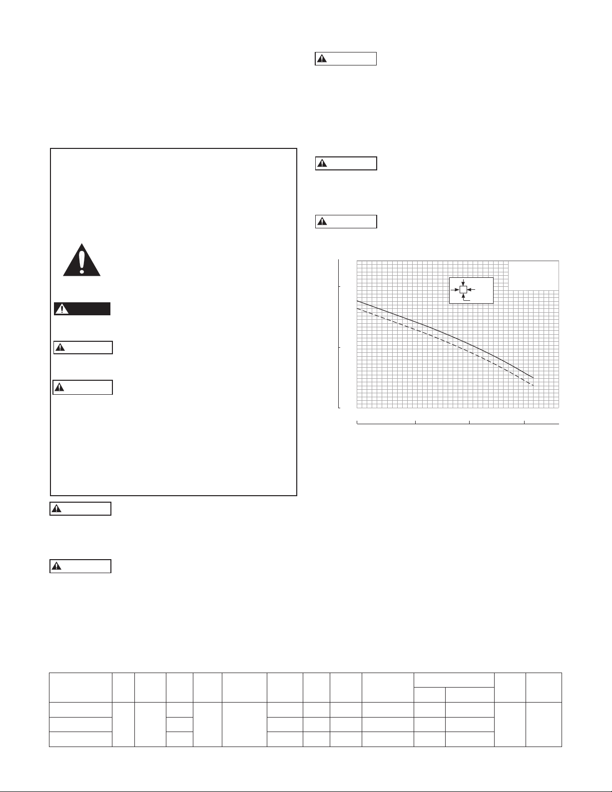
METERS FEET
TOTAL DYNAMIC HEAD
CAPACITY
Derate at
200ºF (93ºC)
68ºF (20ºC)
DANGER
WARNING
CAUTION
WARNING
WARNING
WARNING
WARNING
WARNING
INTRODUCTION
Bell & Gossett High Temperature 3885 Series Efuent
pumps are recommended for use in High Temperature
applications up to 200ºF. The High Temperature 3885 Pump
handles ¾” solids . Common applications include boiler
blow down and High Temperature condensate. Pump
should be operated with a High Temperature oat switch
sold separately.
aged equipment, provide unsatisfactory performance, and
may void manufacturer’s warranty.
Standard units are not designed for use in
swimming pools, open bodies of water,
hazardous liquids, or where ammable gases exist. These
uids and gases may be present in containment areas. Tank
or wetwell must be vented per local codes.
Only pumps specically Listed for Class 1, Division 1 are
allowable in hazardous liquids and where ammable gases
SAFETY INSTRUCTIONS
TO AVOID SERIOUS OR FATAL PERSONAL INJURY
OR MAJOR PROPERTY DAMAGE, READ AND
FOLLOW ALL SAFETY INSTRUCTIONS IN MANUAL
AND ON PUMP.
THIS MANUAL IS INTENDED TO ASSIST IN THE
INSTALLATION AND OPERATION OF THIS UNIT AND
MUST BE KEPT WITH THE PUMP.
This is a SAFETY ALERT SYMBOL.
When you see this symbol on the pump or
in the manual, look for one of the following
signal words and be alert to the potential
for personal injury or property damage.
Warns of hazards that WILL cause serious
personal injury, death or major property
damage.
Warns of hazards that CAN cause serious
personal injury, death or major property
damage.
Warns of hazards that CAN cause personal
injury or property damage.
NOTICE: INDICATES SPECIAL INSTRUCTIONS WHICH
ARE VERY IMPORTANT AND MUST BE
may exist. See specic pump catalog bulletins or pump
nameplate for all agency Listings.
Disconnect and lockout electrical power
before installing or servicing any electrical
equipment. Many pumps are equipped with automatic
thermal overload protection which may allow an overheated
pump to restart unexpectedly.
Do not use pump ammalde or explosive
liquids. Pump is for water only.
PERFORMANCE
40
35
10
30
WEHT03M
25
20
5
15
10
5
0
0
01020304050607
0
5
FOLLOWED.
THOROUGHLY REVIEW ALL INSTRUCTIONS AND
WARNINGS PRIOR TO PERFORMING ANY WORK
ON THIS PUMP.
MAINTAIN ALL SAFETY DECALS.
This product can expose you to chemicals
including Lead, which is known to the State
of California to cause cancer and birth defects or other
reproductive harm. For more information go to:
www.P65Warnings.ca.gov.
All electrical work must be performed by a
qualied technician. Always follow the National Electrical Code (NEC), or the Canadian Electrical Code,
as well as all local, state and provincial codes. Code questions should be directed to your local electrical inspector.
PRE-INSTALLATION CHECKS
Open all cartons and inspect for shipping damage. Report
any damage to your supplier or shipping carrier immediately.
Important: Always verify that the pump nameplate Amps,
Voltage, Phase and HP ratings match your control panel and
power supply.
This pump is oil-lled. If there are any signs of oil leakage
or if the unit has been stored for an extended period check
the oil level in the motor dome and the seal housing, if so
equipped.
Check the motor cover oil level through the pipe plug on
top of the unit. The motor chamber oil should just cover the
motor. Do not overll, leave room for expansion!
Failure to follow electrical codes and OSHA safety standards
may result in personal injury or equipment damage. Failure
to follow manufacturer’s installation instructions may result in
To check the seal housing oil level, where used, lay the unit
on its side with the ll plug at 12 o’clock. Remove the plug.
electrical shock, re hazard, personal injury or death, dam-
MODELS
Order
Number
WEHT0311M
HP Phase Volts RPM
115
0.33 1
WEHT0312M 230 6.1 16.5 J 54 11.7 5.6
Impeller
Dia. (In.)
1750 5.38
Max.
Amps
LRA
KVA
Code
Full Load
Motor Eff.
12.0 31.1 J 55 9.3 1.4
*Add P1 to the end of the order number to include an ultra hi-temp oat switch in the purchase.
Replacement part numbers for oat: A2HT31 – 115V and A2HT32 – 208 and 230V (20' cord length).
Resistance
Start Line-Line
MODEL: WEHT03xxM
SIZE: 2" Discharge
RPM: 1750
HP: .33 HP
3
/4" Diameter
2 GPM
1 FT
10
SOLIDS:
Wt.
(Lbs.)
15
Cord
Length
0GPM
m3/hr
56 20'WEHT0318M 208 7.3 19.5 K 51 9.1 4.2
3
Page 4
WARNING
Hazardous
voltage
WARNING
WARNING
WARNING
Hazardous voltage
can shock, burn or
cause death.
The oil should be within ½” (13mm) of the top. If low, rell
with an ASTM 150 turbine oil. Replace the plug.
Oil is available in 5 gallon cans through our distributors. You
can also source oil locally at motor repair shops. Typical oil
brands are: Shell Turbo 32, Sunoco Sunvis 932, Texaco Regal
R&O 32, Exxon Nuto 32 and Mobil DTE Light.
Check the strain relief nut on power cable strain assemblies.
Power cables should be torqued to 75 in. lbs., cable supplied
is for high temp use.
Warranty does not cover damage caused by connecting
pumps and controls to an incorrect power source (voltage/
phase supply).
Record the model numbers and serial numbers from the
pumps and control panel on the front of this instruction
manual for future reference. Give it to the owner or afx it to
the control panel when nished with the installation.
FOR ALL SES PUMP INSTALLATIONS
LIFTING OF PUMP
DO NOT LIFT, CARRY OR HANG
PUMP BY THE ELECTRICAL CABLES.
DAMAGE TO THE ELECTRICAL
CABLES CAN CAUSE SHOCK, BURNS
OR DEATH.
Lift the pump with an adequately sized chain or cable attached to the lifting eye bolt. DO NOT damage electrical
cables while raising and lowering unit.
OPTIONAL GUIDE RAIL
OR LIFT-OUT SYSTEM
In many efuent and sewage basins or lift stations it is advisable to install the pump on a guide rail system or on a lift-out
adapter to facilitate installation and removal for inspection
and/or service. Most codes do not allow personnel to enter a
wetwell without the correct protective equipment and training. Guide rails are designed to allow easy removal of the
pump without the need for entry into the wetwell or need
to disturb piping. The guide rail or lift-out adapter should
locate the pump opposite the inuent opening preventing
stagnate areas where solids can settle. The basin or pit must
be capable of supporting the weight of the pump and guide
rail. The pit oor must be at.
NOTICE: FOLLOW THE INSTRUCTIONS THAT ARE
PROVIDED WITH THE GUIDE RAIL ASSEMBLY.
PIPING
Discharge piping should be no smaller than the pump
discharge diameter and kept as short as possible, avoiding
unnecessary ttings to minimize friction losses. Piping should
be rated for high temperatures if used in high temperature
applications.
Install an adequately sized check valve matched to the solids
handling capability of the pump to prevent uid backow.
Backow can allow the pump to “turbine” backwards and
may cause premature seal and/or bearing wear. If the pump
is turning backwards when it is called on to start the increased torque may cause damage to the pump motor and/
or motor shaft and some single-phase pumps may actually
run backwards.
4
Install an adequately sized gate valve AFTER the check valve
for pump, plumbing and check valve maintenance.
Important – Before pump installation. Drill a 3⁄16” (4.8mm)
relief hole in the discharge pipe. It should be located within
the wetwell, 2” (51mm) above the pump discharge but below the check valve. The relief hole allows any air to escape
from the casing. Allowing liquid into the casing will insure
that the pump can start when the liquid level rises. Unless a
relief hole is provided, a bottom intake pump could “air lock”
and will not pump water even though the impeller turns.
All piping must be adequately supported, so as not to impart
any piping strain or loads on the pump.
The pit access cover must be of sufcient size to allow for
inspection, maintenance and crane or hoist service.
WIRING AND GROUNDING
Important notice: Read Safety Instructions before
proceeding with any wiring.
Use only stranded copper wire to pump/motor and
ground. The ground wire must be at least as large as
the power supply wires. Wires should be color coded
for ease of maintenance and troubleshooting.
Install wire and ground according to the National Electrical Code (NEC), or the Canadian Electrical Code, as
well as all local, state and provincial codes.
Install an all leg disconnect switch where required by
code.
Disconnect and lockout electrical power before performing any service or installation.
The electrical supply voltage and phase must match
all equipment requirements. Incorrect voltage or
phase can cause re, motor and control damage, and
voids the warranty.
All splices must be waterproof. If using splice kits follow manufacturer’s instructions.
Select the correct type and NEMA grade
junction box for the application and location. The junction box must insure dry, safe
wiring connections.
Seal all controls from gases present which
may damage electrical components.
FAILURE TO PERMANENTLY GROUND
THE PUMP, MOTOR AND CONTROLS
BEFORE CONNECTING TO POWER
CAN CAUSE SHOCK, BURNS OR DEATH.
SELECTING AND WIRING
PUMP CONTROL PANELS AND SWITCHES
FLOAT SWITCH TYPES
High Temp oats can be purchased for High Temp applications. They are normally open (NO) for pump down operations.
These wide-angle, pump down switches may be used as
direct connected pump switches or as control switches.
Page 5

SETTING THE FLOAT SWITCHES
WARNING
Hazardous voltage
can shock, burn or
cause death.
DANGER
Hazardous Machinery
!
There are no absolute rules for where to set the oat switches, it varies from job to job.
Suggested Rules to Follow:
All oats should be set below the Inlet pipe!
Off Float: Best: set so the water level is always above the top
of the pump (motor dome). Next Best: set so the water level
is not more than 6" below the top of the pump.
On Float: set so the volume of water between the On and
Off oats allows pumps of 1½ HP and under to operate for 1
minute minimum. Two (2) HP and larger pumps should run
a minimum of 2 minutes. Basin literature states the gallons of
storage per inch of basin height.
Lag/Alarm Float(s): should be staggered above the Off and
On oats. Try to use most of the available storage provided
by the basin, save some space for reserve storage capacity.
See Diagrams and Charts in Float Switch Chart Section.
PANEL WIRING DIAGRAMS
Our control panels are shipped with instructions and wiring
diagrams. Use those instructions in conjunction with this
IOM. Electrical installation should be performed only by
qualied technicians. Any problem or questions pertaining
to another brand control must be referred to that control
supplier or manufacturer. Our technical people have no
technical schematics or trouble shooting information for
other companies' controls.
ALARMS
We recommend the installation of an alarm on all Wastewater pump installations. Many standard control panels come
equipped with alarm circuits. If a control panel is not used,
a stand alone high liquid level alarm is available. The alarm
alerts the owner of a high liquid level in the system so they
can contact the appropriate service personnel to investigate
the situation.
SINGLE PHASE PUMPS
Single phase (1Ø) pumps may be operated using a piggy-
back or hard wired oat switch, a contactor, or a Simplex or
Duplex control panel. See Figures 1 and 4.
All 1/3 and ½ HP, 115 or 230 volt pumps, and some ¾ and 1
HP pumps, are supplied with plug style power cords. They
may be plugged into piggyback oat switches for simple
installations. It is allowable to remove the plugs in order to
hardwire or connect to a Simplex or Duplex controller. Removing the plug neither voids the warranty nor violates the
agency Listings. See Figure 4.
Pumps with bare lead power cords can be hard-wired to a
oat switch, wired to a 1Ø contactor, a Simplex controller or
a Duplex controller. Always verify that the oat switch is rated
for the maximum run amperage, maximum starting amperage, and the HP rating on the pump. Single-phase wastewater pumps contain on-winding overloads, unless noted on
the pump nameplate. See Figure 1.
PLUG-CONNECTED UNITS MUST
BE CONNECTED TO A PROPERLY
GROUNDED, GROUNDING TYPE
RECEPTACLE.
ON NON-PLUG UNITS, DO NOT
REMOVE CORD AND STRAIN RELIEF.
DO NOT CONNECT CONDUIT TO PUMP.
SINGLE PHASE CONTROL PANELS:
Control panels are available as Simplex (controls 1 pump) or
Duplex (controls 2 pumps). Our standard SES Series Panels
are available with many standard features and can be built
with our most popular options. We also custom build panels
which offer many more design options than the SES panels.
Custom control panels are available in many different con-
gurations. Custom panel quote requests may be forwarded
to Customer Service through any authorized distributor.
Our “SES” Duplex panels feature a solid-state printed circuit
board design with standard high level alarm circuits. Other
standard features are: an auxiliary dry alarm contact for
signaling a remote alarm and oat switch position indicator
lights.
INSTALLATION
Connect the pump(s) to the guide rail pump adapters or to
the discharge piping. Slide rail bases should be anchored to
the wetwell oor.
Complete all wiring per the control panel wiring diagrams
and NEC, Canadian, state, provincial and/or local codes.
This a good time to check for proper rotation of the motors/
impellers.
DO NOT PLACE HANDS IN PUMP
SUCTION WHILE CHECKING
MOTOR ROTATION. TO DO SO WILL
CAUSE SEVERE PERSONAL INJURY.
Always verify correct rotation. Correct
rotation is indicated on the pump casing.
Three phase motors are reversible. It is
allowable to bump or jog the motor for a
few seconds to check impeller rotation. It
is easier to check rotation before installing
the pump. Switch any two power leads to
reverse rotation.
Lower the pump(s) into the wetwell.
Check to insure that the oats will operate freely and not
contact the piping.
OPERATION
Once the piping connections are made and checked you
can run the pumps.
Piggyback Switch Operation – Plug the piggyback switch
into a dedicated grounded outlet and then plug the pump
into the switch. Test the pump by lling the wetwell until the
pump goes On. If the pumps run but fail to pump, they are
probably air locked, drill the relief holes per the instructions
in the Piping Section.
Check the operating range to insure a minimum one minute
run time and that the pump goes Off in the correct position.
Control Panel Operation – Fill the wetwell with clear water.
Use the pump H-O-A (Hand-Off-Automatic) switches in
Hand to test the pumps. If they operate well in Hand proceed to test Automatic operation. If the pumps run but fail to
pump, they are probably air locked, drill the relief holes per
the instructions in the Piping Section.
Place Control Panel switch(es) in Automatic position and
thoroughly test the operation of the ON, OFF, and Alarm
5
Page 6

oats by lling the wetwell with clear water. Important:
Inlet
Alarm SW3
Pump On SW2
Pump Off SW1
Discharge
Inlet
Alarm SW4
Lag Pump On
SW3
Pump Off
SW1
Discharge
Lead Pump On
SW2
Failure to provide a Neutral from the power supply to a 1Ø,
230 volt Control Panel will not allow the panel control circuit
to operate. The Neutral is necessary to complete the 115
volt control circuit.
Check voltage and amperage and record the data on the
front of this manual for future reference. Compare the amperage readings to the pump nameplate maximum amperage. If higher than nameplate amperage investigate cause.
Operating the pump off the curve, i.e. with too little head or
with high or low voltage will increase amperage. The motor
will operate properly with voltage not more than 10% above
or below pump nameplate ratings. Performance within this
range will not necessarily be the same as the published
FLOAT SWITCH AND PANEL CHART
The purpose of this chart is to show the required switch
quantities and the function of each switch in a typical wastewater system. The quantities required vary depending on
the switch type, single-action or wide-angle. Switch quantities also vary by panel type: simplex with and without alarms,
and duplex with alarms.
Duplex Panels using single-action switches:
Three Float Panel Wiring
SW1 Bottom Pumps Off
SW2 Middle 1st Pump On
SW3 Top 2nd Pump & Alarm On
performance at the exact rated nameplate frequency and
voltage. Correct the problem before proceeding. Three
phase unbalance is also a possible cause. See Three Phase
Power Unbalance and follow the instructions.
Reset the Alarm circuit, place pump switch(es) in the Automatic position and Control Switch in ON position. The
system is now ready for automatic operation.
Explain the operation of the pumps, controls and alarms to
the end user. Leave the paperwork with the owner or at the
control panel if in a dry, secure location.
Simplex Panel using wide-angle switches:
Simplex Panel with Alarm
SW1 Bottom Pump On/Off
SW2 Top Alarm On/Off
Simplex Panel with No Alarm
SW1 Pump On/Off
Four Float Panel Wiring ➁
SW1 Bottom Pumps Off
SW2 2nd 1st Pump On
SW3 3rd 2nd Pump On
SW4 Top Alarm On
Duplex Panels using wide-angle switches:
Three Float Panel Wiring
SW1 Bottom 1st Pump On/Both Off
SW2 Top 2nd Pump & Alarm On
Four Float Panel Wiring
SW1 Bottom 1st Pump On/Both Off
SW2 Middle 2nd Pump On
SW3 Top Alarm On
Simplex Panel using single-action switches:
Simplex Panel with Alarm ①
SW1 Bottom Pump Off
SW2 Middle Pump On
SW3 Top Alarm On/Off
Simplex Panel with No Alarm
SW1 Bottom Pump Off
SW2 Top Pump On
Simplex ①
6
Duplex ➁
Page 7

INSULATION RESISTANCE READINGS
6" (15.3 cm)
6" (15.3 cm)
8" (20.3 cm) TURN ON LEVEL
WEIGHT
Normal Ohm and Megohm Values between all leads and ground
Condition of Motor and Leads Ohm Value Megohm Value
A new motor (without drop cable). 20,000,000 (or more) 20 (or more)
A used motor which can be reinstalled in well. 10,000,000 (or more) 10 (or more)
Motor in well. Readings are for drop cable plus motor.
New motor. 2,000,000 (or more) 2 (or more)
Motor in good condition. 500,000 - 2,000,000 .5 - 2
Insulation damage, locate and repair. Less than 500,000 Less than .5
Insulation resistance varies very little with rating. Motors of all HP, voltage and phase ratings have similar values of
insulation resistance.
Insulation resistance values above are based on readings taken with a megohmmeter with a 500V DC output.
Readings may vary using a lower voltage ohmmeter, consult factory if readings are in question.
ENGINEERING DATA
Engineering data for specic models may be found in your catalog and on our website (address is on the cover).
Control panel wiring diagrams are shipped with the control panels. Please use the control panel drawings in
conjunction with this instruction manual to complete the wiring.
Minimum Submergence
Continuous
Duty
Pumpmaster and Pumpmaster Plus - Hard Wired
Determining Pumping Range
Fully Submerged
Figure 1
PUMP OPERATION
Continuous
Operation
Single-Action Float Switch
Maximum Fluid Temperature
200º F 93º C
"Typical" Installation
Figure 3
Wide-Angle Float Switch
Pump plug
Piggyback
switch plug
Figure 2
Pumping
range
Figure 4
7
Page 8

TROUBLESHOOTING
WARNING
Hazardous
voltage
FAILURE TO DISCONNECT AND LOCKOUT ELECTRICAL
POWER BEFORE ATTEMPTING ANY SERVICE CAN CAUSE
SHOCK, BURNS OR DEATH.
SYMPTOM PROBABLE CAUSE RECOMMENDED ACTION
MOTOR NOT RUNNING Motor thermal protector tripped. Allow motor to cool. Insure minimum pump
submergence. Clear debris from casing and impeller.
NOTE: If circuit breaker
Open circuit breaker or blown fuse. Determine cause, call a qualied electrician.
“OPENS” repeatedly,
DO NOT reset. Call
Pump impeller binding or jammed. Check motor amp draw. If two or more times higher
qualied electrician.
than listed on pump nameplate, impeller is locked,
a) Manual operation Power cable is damaged. motor bearings or shaft is damaged. Clear
Resistance between power leads and ground should
b) Automatic operation No neutral wire read innity. If any reading is incorrect, call a
connected to control panel. qualied electrician.
Inadequate electrical connection Inspect control panel wiring. Call a qualied
in control panel. electrician.
NOTE: Check the pump in
Defective liquid level switch. With switch disconnected, check continuity while
manual mode rst to con-
activating liquid level switch. Replace switch, as
rm operation. If pump
required.
operates, the automatic
Insufcient liquid level to Allow liquid level to rise 3" to 4" (76 mm - 101 mm)
control or wiring is at fault.
activate controls. above turn-on level.
If pump does not operate,
Liquid level cords tangled. Untangle cords and insure free operation.
see above.
PUMP WILL NOT Liquid level cords tangled. Untangle cords and insure free operation.
TURN OFF
Pump is air locked. Shut off pump for approximately one minute, then
restart. Repeat until air lock clears. If air locking
persists in a system with a check valve, a 3⁄16" (4.8 mm)
hole may be drilled in the discharge pipe approximately
2" (51 mm) above the discharge connection.
Inadequate electrical connection
in control panel.
debris from casing and impeller, consult with dealer.
Inuent ow is matching pump’s Larger pump may be required.
discharge capacity.
LITTLE OR NO LIQUID Check valve installed backwards, Check ow arrow on valve and check valve
DELIVERED BY PUMP plugged or stuck closed. operation.
Excessive system head. Consult with dealer.
Pump inlet plugged. Inspect and clear as required.
Improper voltage or wired Check pump rotation, voltage and wiring.
incorrectly. Consult with qualied electrician.
Pump is air locked. See recommended action, above.
Impeller is worn or damaged. Inspect impeller, replace as required.
Liquid level controls defective Inspect, readjust or replace as required.
or improperly positioned.
PUMP CYCLES Discharge check valve inoperative. Inspect, repair or replace as required.
CONSTANTLY
Liquid level controls defective or Inspect, readjust or replace as required.
improperly positioned.
Inuent excessive for this size Consult with dealer.
pump.
8
Sewage containment area too small. Consult with dealer.
Page 9

TYPICAL INSTALLATIONS
Typical Efuent, Sewage and
Dewatering Pump Installations
9
Page 10

NOTES
10
Page 11

NOTES
11
Page 12

LIMITED CONSUMER WARRANTY
For goods sold for personal, family or household purposes, Seller warrants the goods purchased hereunder (with the exception of membranes,
seals, gaskets, elastomer materials, coatings and other “wear parts” or consumables all of which are not warranted except as otherwise provided
in the quotation or sales form) will be free from defects in material and workmanship for a period of one (1) year from the date of installation or
eighteen (18) months from the product date code, whichever shall occur rst, unless a longer period is provided by law or is specied in the product
documentation (the “Warranty”).
Except as otherwise required by law, Seller shall, at its option and at no cost to Buyer, either repair or replace any product which fails to conform
with the Warranty provided Buyer gives written notice to Seller of any defects in material or workmanship within ten (10) days of the date when any
defects or non-conformance are rst manifest. Under either repair or replacement option, Seller shall not be obligated to remove or pay for the
removal of the defective product or install or pay for the installation of the replaced or repaired product and Buyer shall be responsible for all other
costs, including, but not limited to, service costs, shipping fees and expenses. Seller shall have sole discretion as to the method or means of repair
or replacement. Buyer’s failure to comply with Seller’s repair or replacement directions shall terminate Seller’s obligations under this Warranty and
render this Warranty void. Any parts repaired or replaced under the Warranty are warranted only for the balance of the warranty period on the parts
that were repaired or replaced. The Warranty is conditioned on Buyer giving written notice to Seller of any defects in material or workmanship of
warranted goods within ten (10) days of the date when any defects are rst manifest.
Seller shall have no warranty obligations to Buyer with respect to any product or parts of a product that have been: (a) repaired by third parties other
than Seller or without Seller’s written approval; (b) subject to misuse, misapplication, neglect, alteration, accident, or physical damage; (c) used in a
manner contrary to Seller’s instructions for installation, operation and maintenance; (d) damaged from ordinary wear and tear, corrosion, or chemical
attack; (e) damaged due to abnormal conditions, vibration, failure to properly prime, or operation without ow; (f) damaged due to a defective
power supply or improper electrical protection; or (g) damaged resulting from the use of accessory equipment not sold or approved by Seller. In any
case of products not manufactured by Seller, there is no warranty from Seller; however, Seller will extend to Buyer any warranty received from Seller’s
supplier of such products.
THE FOREGOING WARRANTY IS PROVIDED IN PLACE OF ALL OTHER EXPRESS WARRANTIES. ALL IMPLIED WARRANTIES, INCLUDING BUT
NOT LIMITED TO THE IMPLIED WARRANTIES OF MERCHANTABILITY AND FITNESS FOR A PARTICULAR PURPOSE, ARE LIMITED TO ONE (1)
YEAR FROM THE DATE OF INSTALLATION OR EIGHTEEN (18) MONTHS FROM THE PRODUCT DATE CODE , WHICHEVER SHALL OCCUR FIRST.
EXCEPT AS OTHERWISE REQUIRED BY LAW, BUYER’S EXCLUSIVE REMEDY AND SELLER’S AGGREGATE LIABILITY FOR BREACH OF ANY OF THE
FOREGOING WARRANTIES ARE LIMITED TO REPAIRING OR REPLACING THE PRODUCT AND SHALL IN ALL CASES BE LIMITED TO THE AMOUNT
PAID BY THE BUYER FOR THE DEFECTIVE PRODUCT. IN NO EVENT SHALL SELLER BE LIABLE FOR ANY OTHER FORM OF DAMAGES, WHETHER
DIRECT, INDIRECT, LIQUIDATED, INCIDENTAL, CONSEQUENTIAL, PUNITIVE, EXEMPLARY OR SPECIAL DAMAGES, INCLUDING BUT NOT LIMITED
TO LOSS OF PROFIT, LOSS OF ANTICIPATED SAVINGS OR REVENUE, LOSS OF INCOME, LOSS OF BUSINESS, LOSS OF PRODUCTION, LOSS OF
OPPORTUNITY OR LOSS OF REPUTATION.
Some states do not allow limitations on how long an implied warranty lasts, so the above limitation may not apply to you. Some states do not allow
the exclusion or limitation of incidental or consequential damages, so the above exclusions may not apply to you. This warranty gives you specic
legal rights, and you may also have other rights which may vary from state to state.
To make a warranty claim, check rst with the dealer from whom you purchased the product or visit www.xyleminc.com for the name and location of
the nearest dealer providing warranty service.
Xylem Inc.
2881 East Bayard Street Ext., Suite A
Seneca Falls, NY 13148
Phone: (866) 325-4210
Fax: (888) 322-5877
www.xylem.com/bellgossett
Bell & Gossett is a trademark of Xylem Inc. or one of its subsidiaries.
© 2019 Xylem Inc. IM249 Revision Number 3 March 2019
 Loading...