

Bell & Gossett VSX, VSH, VSC, VSCS Instruction Manual
INSTRUCTION MANUAL
P5002169
REVISION E
INSTALLER: PLEASE LEAVE THIS MANUAL FOR THE OWNER’S USE.
Series VSX
VSH, VSC®, and VSCS® Models
Centrifugal Pumps

TABLE OF CONTENTS
INTRODUCTION .............................................................. 1
DESCRIPTION
PUMP APPLICATION
OPERATIONAL LIMITS ................................................ 1
Maximum Suction Pressure ................................... 1
Maximum Working Pressure ................................. 1
SEAL OPERATING LIMITS ........................................... 1
Mechanical Seals .................................................... 1
Packing ..................................................................... 1
PUMP IDENTIFICATION .............................................. 2
SAFETY INSTRUCTIONS ............................................. 3
ADDITIONAL SAFETY INSTRUCTIONS ..................... 4
Electrical Safety ....................................................... 4
Thermal Safety ........................................................ 4
Mechanical Safety ................................................... 4
GENERAL INSTRUCTIONS
PURPOSE OF THE MANUAL ...................................... 5
RECEIVING THE PUMP ................................................ 5
STORAGE REQUIREMENTS ........................................ 5
SAFE HANDLING REQUIREMENTS ........................... 5
LOCATION .................................................................... 7
Important ................................................................. 7
FOUNDATION .............................................................. 7
BASE PLATE SETTING ................................................. 8
Optional Grouting .................................................. 8
ROTATION .................................................................... 8
COUPLING ALIGNMENT ............................................ 8
To align using straight edge and calipers ........... 9
To align using dial indicator ................................ 10
Final Alignment ..................................................... 12
SUCTION AND DISCHARGE PIPING ....................... 12
Suction Piping ....................................................... 13
Valves in Suction Piping ....................................... 14
Discharge Piping .................................................. 14
Pressure Gauges ................................................... 15
Pump Insulation .................................................... 15
PUMP SEALING .......................................................... 15
Mechanical Seals .................................................. 15
Packing ................................................................... 15
VEE-CUT IMPELLER TRIMS ....................................... 16
OPERATION
FLUSHING ................................................................... 18
FILLING ....................................................................... 18
PRIMING...................................................................... 18
PRE-START CHECKS .................................................. 18
STARTING ................................................................... 19
OPTIONAL CHECKLIST
FREEZE PROTECTION
FIELD TESTS ............................................................... 19
MAINTENANCE
GENERAL MAINTENANCE AND PERIODIC
INSPECTION
LUBRICATION
Pump Bearings ...................................................... 20
Couplings .............................................................. 20
SEAL INFORMATION................................................. 20
Mechanical Seals
Packing (Non-Asbestos)
MAINTENANCE OF FLOOD DAMAGED PUMPS ....21
.............................................................. 1
................................................... 1
............................................. 5
.................................................................... 18
............................................. 19
............................................... 19
............................................................. 20
............................................................... 20
............................................................ 20
.................................................. 20
....................................... 20
TROUBLESHOOTING .................................................... 22
GUARDS
SERVICE
NOTE: The information contained in this book is
intended to assist operating personnel by providing
information about the characteristics of the purchased
equipment. It does not relieve the user of their responsibility of using accepted engineering practices
in the installation, operation, and maintenance of this
equipment.
For additional questions, contact
BELL & GOSSETT
(847) 966-3700
http://www.bellgossett.com
.......................................................................... 24
ANSI/OSHA COUPLING GUARD
REMOVAL/INSTALLATION
Removal ................................................................. 24
Installation ............................................................. 24
BRACKET GUARDS .................................................... 25
........................................................................... 26
GENERAL DISASSEMBLY PROCEDURES ................ 27
SHUTDOWN ............................................................... 27
DISASSEMBLY PROCEDURE TO REMOVE BEARING
FRAMES – ALL PUMPS .................................... 27
DISASSEMBLY PROCEDURE TO REMOVE
STANDARD MECHANICAL SEALS ................ 28
DISASSEMBLY PROCEDURE TO REMOVE
STUFFING BOX AND PACKING ..................... 29
DISASSEMBLY PROCEDURE TO REMOVE
CARTRIDGE SEALS .......................................... 29
DISASSEMBLY PROCEDURE TO REMOVE
COVERPLATES AND SHAFT ASSEMBLY –
ALL PUMPS ....................................................... 30
ASSEMBLY PROCEDURE TO INSTALL
COVERPLATES AND SHAFT ASSEMBLY –
ALL PUMPS ....................................................... 30
ASSEMBLY PROCEDURE TO INSTALL STANDARD
MECHANICAL SEALS ...................................... 32
ASSEMBLY PROCEDURE TO INSTALL STUFFING
BOX AND PACKING ........................................ 33
ASSEMBLY PROCEDURE TO INSTALL CARTRIDGE
SEALS ................................................................ 33
ASSEMBLY PROCEDURE TO INSTALL BEARING
FRAMES – ALL PUMPS .................................... 34
GENERAL ASSEMBLY INSTRUCTIONS .................... 35
TO CHANGE ROTATION .......................................... 36
TO CHANGE STANDARD MECHANICAL SEALS ... 37
TO CHANGE CARTRIDGE SEALS ............................ 37
TO CHANGE THE PACKING OR SLEEVE ................ 37
ORDERING PARTS ..................................................... 37
DEALER SERVICING .................................................. 37
............................. 24

INTRODUCTION
DESCRIPTION
The Series VSX centrifugal pumps are framemounted pumps that feature high efficiency,
rugged construction, compact design, footmounted volute, alignment-friendly coupling, and
unitized seals. These features, along with
the vertically split case make installation,
operation, and service easy to perform.
WARNING: This product can expose you
to chemicals including Lead, which is known to
the State of California to cause cancer and birth
defects or other reproductive harm. For more
information go to: www.P65Warnings.ca.gov.
PUMP APPLICATION
The standard Series VSX centrifugal pump’s
bronze fitted c
onstruction makes it ideal for service
with the following liquids: hydronic cooling or
heating, boiler feed water, condensate,
pressure boosting, general pumping, unheated
domestic and fresh water, and benign liquids.
For other applications contact your local Bell &
sett representative.
Gos
OPERATIONAL LIMITS
Unless special provisions have been made for
your pump by Bell & Gossett, the operational
limits
for Series VSX pumps are as follows:
Maximum Suction Pressure
Table 1 shows the maximum suction
pressures allowed for pump size and seal
type:
Table 1: Maximum Suction Pressures
Unitized Seal Balanced Seal
2” Seal Sizes
4x6x10.5
5x6x10.5
5x6x13.5
6x8x10.5
6x8x13.5
8x10x10.5
2.5” Seal Sizes
8x10x13.5
10x12x10.5
10x12x13.5
3” Seal Sizes
12x14x13.5
14x16x13.5
3.5” Seal Sizes
12x14x17.5
175 psi 300 psi
175 psi 300 psi
160 psi 300 psi
125 psi 300 psi
SEAL OPERATING LIMITS
Mechanical Seals
NOTE: For
use on closed or open systems
that are relatively free of dirt and/or other
abrasive particles.
°
Unitized EPR/Car/SiC: 0
F to 300°F
Temperature range; 6.5 to 8.5 pH range
°
Unitized Viton/Car/SiC: 0
F to 225°F
Temperature range; 6.5 to 8.5 pH range
°
Unitized EPR/Graphite Loaded SiC: 0
°
F Temperature range; 7 to 12.5 pH range
300
Balanced EPR/Graphite Loaded SiC: 0
°
F Temperature range; 7 to 12.5 pH range
300
Balanced Viton/Graphite Loaded SiC: 0
°
F Temperature range; 7 to 12.5 pH range
225
CAUTION: Equipment Damage
F to
°
F to
°
F to
To prevent premature seal failure or possible
injury, the unitized seals should not be used as an
alternate or substitute for the balanced seals
installed in a high suction pressure rated VSX
pump.
Failure to follow these instructions could result in
serious property damage and/or moderate
personal injury.
Packing
NOTE: For use on open or closed systems
that require a large amount of makeup water,
as well as systems that are subjected to
widely varying chemical conditions and solids
buildup.
Braided Graphite PTFE:
0°F to 200°F Temperature range; 7 to 9 pH
range
Maximum Working Pressure
Listed on pump nameplate.
1
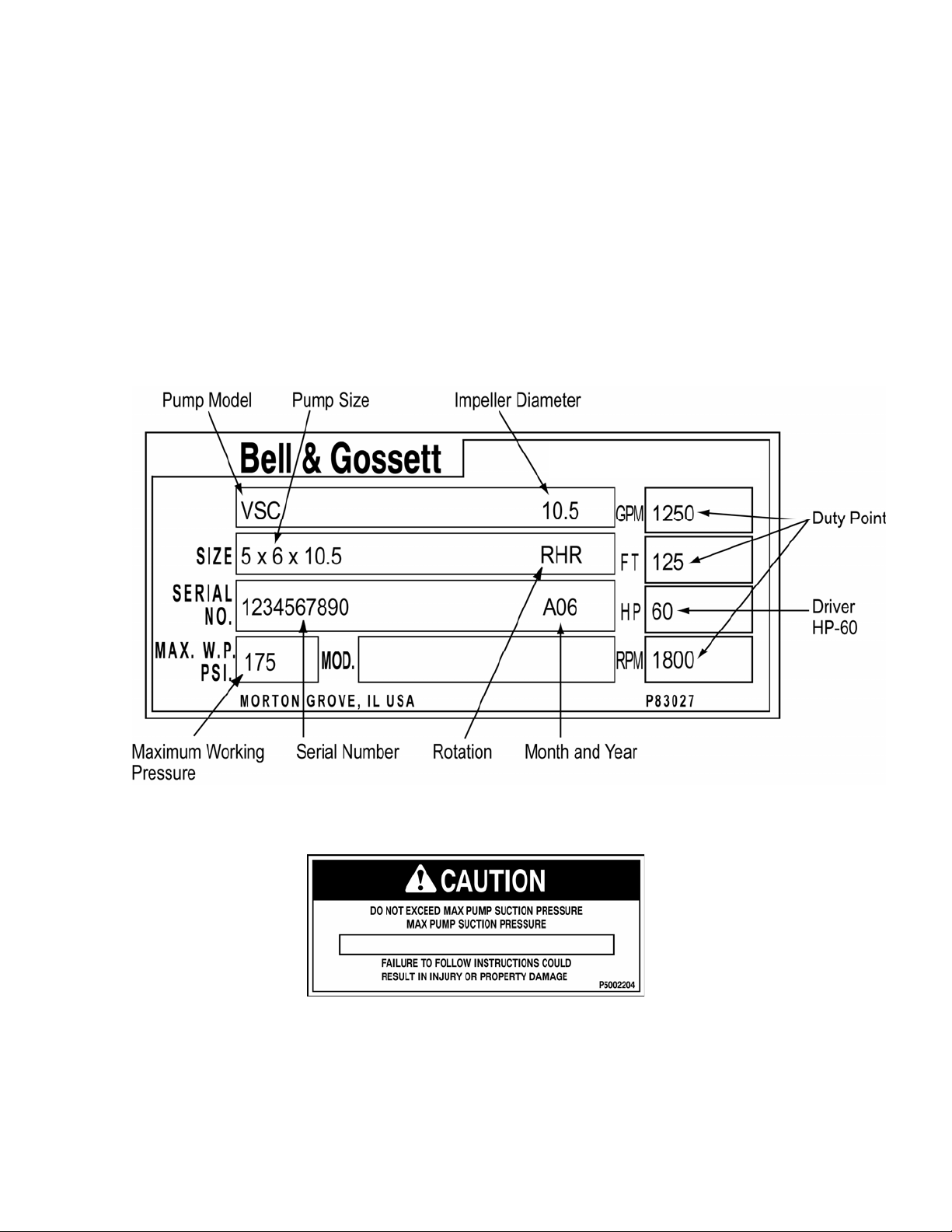
PUMP IDENTIFICATION
Bell & Gossett pumps are designated by a series
of numbers such as Series VSX, Model VSH,
VSC, or VSCS. The pump nameplate gives
identification and rating information as shown in
Figures 1 and 2.
Permanent records for this pump are referenced
by the serial number and it must be used with all
correspondence and spare parts orders.
Figure 1: Rating Plate
Figure 2: Suction Limitation
2
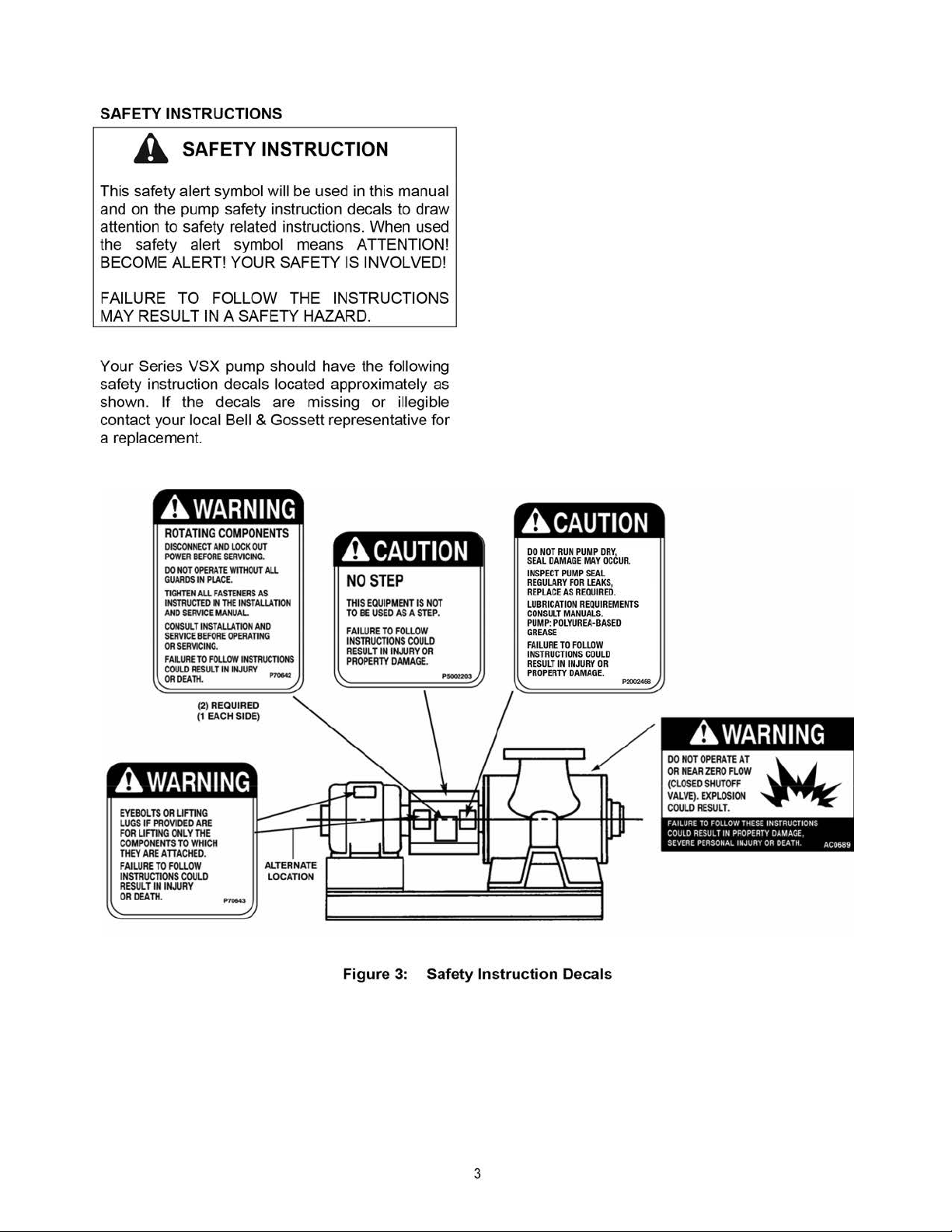
ADDITIONAL SAFETY INSTRUCTIONS
Electrical Safety
WARNING: Electrical Shock Hazard
Electrical connections to be made by a qualified
electrician in accordance with all applicable codes,
ordinances, and good practices.
WARNING: Rotating Components
Hazard
Do not operate the pump without all guards in
place.
Failure to follow these instructions could result in
serious personal injury or death, or property
damage.
WARNING: Electrical Overload Hazard
Three-phase motors must have properly sized
heaters to provide overload and under voltage
protection. Single-phase motors have built-in
overload protectors.
Failure to follow these instructions could result in
serious personal injury or death, or property
damage
Thermal Safety
WARNING: Extreme Temperature Hazard
If pump, motor, or piping are operating at
extremely high or low temperatures, guarding or
insulation is required.
Failure to follow these instructions could result in
serious personal injury or death, or property
damage.
Mechanical Safety
WARNING: Unexpected Startup Hazard
Failure to follow these instructions could result in
serious personal injury or death, or property
damage.
WARNING: Excessive System Pressure
Hazard
The maximum working pressure of the pump is
listed on the nameplate. Do not exceed this
pressure.
Failure to follow these instructions could result in
serious personal injury or death, or property
damage.
WARNING: Excessive Pressure Hazard
Volumetric Expansion
The heating of water and other fluids causes
volumetric expansion. The associated forces may
cause failure of system components and release
of high temperature fluids. This will be prevented
by installing properly sized and located
compression tanks and pressure relief valves.
Failure to follow these instructions could result in
serious personal injury or death, or property
damage.
Disconnect and lockout power before servicing.
Failure to follow these instructions could result in
serious personal injury or death, or property
damage.
4

GENERAL INSTRUCTIONS
PURPOSE OF THE MANUAL
This manual is furnished to acquaint you with
some of the practical ways to install, operate, and
maintain this pump. Read it completely before
any installation, operation, or maintenance on
your unit and keep it handy for future reference.
Equipment cannot operate well without proper
care. To keep this unit at top efciency, follow the
recommended installation and servicing
procedures outlined in this manual.
RECEIVING THE PUMP
Check the pump for shortages and damage
immediately upon arrival. (An absolute must!)
Prompt reporting of any damage to the carrier’s
agent, with notations made on the freight bill, will
expedite satisfactory adjustment by the carrier.
Pumps and drivers are normally shipped from the
factory mounted on a base plate and paint-
ed with primer and one nish coat. Couplings
may either be completely assembled or have
the coupling hubs mounted on the shafts and
the connecting members removed. When the
connecting members are removed, they will be
packaged in a separate container and shipped
with the pump or attached to the base plate.
Shafts are in alignment when the unit is shipped;
however, due to shipping, the pumps may arrive
misaligned. Alignment must be established
during installation. Bell & Gossett has determined
that proper and correct alignment can only be
made by accepted erection practices. (See the
Foundation, Baseplate Setting, and Coupling
Alignment sections.)
STORAGE REQUIREMENTS
If the unit will not be installed and put into operation immediately upon arrival at the site, or for an
extended shutdown after the unit is in operation,
the following requirements for short-term
storage apply:
• Store in a covered and dry location.
• Store the unit free from excessive cold or
heat (below 32°F and above 110°F), dirt,
and vibration.
• Rotate the shaft by hand several times
(10–15 turns) at least every 30 days.
For initial storage longer than three months, or
for pump shut down after being in operation longer than three months, contact your local sales
and service representative for long-term storage
guidelines.
SAFE HANDLING REQUIREMENTS
WARNING: Falling Objects Hazard
Eyebolts or lifting lugs, if provided, are
for lifting only the components to which
they are attached.
• Personal protective equipment should be
worn when handling this equipment.
• Transportation & installation of this equipment
should only be performed by qualied
personnel.
• A professional rigging company should be
consulted before lifting the pump assembly.
• Only use properly sized, certied lifting
equipment & lifting devices, including slings,
suitably rated for the weights to be lifted.
• Slings, when used, must be of identical
materials to avoid differences in stretch rates.
• Do not use lifting devices that are frayed,
kinked, unmarked, or worn.
• Lifting eyebolts tted on single components
of the assembly (pump or motor) must not
be used to lift the complete assembly.
Failure to observe these instructions could
result in equipment or property damage,
serious injury, or death.
The pump assembly can arrive in a variety of
ways. It can be shipped as pump end only (bare
pump), pump less motor, or pump, motor, &
baseplate. Use the following recommended ways
of handling VSX pump assemblies.
The pump assembly should remain horizontal
during transport and lifting.
5
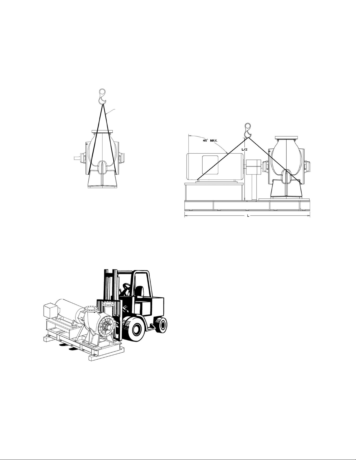
Lifting the pump end only (bare pump) should be
done by placing one end of the slings around or
as close to the volute barrel as possible (See Fig.
4a). After the slings are attached to the unit, recheck to ensure they are securely in place. Make
sure the slings are adjusted to obtain an even lift.
Appropriate lifting device
Figure 4a
Lifting the pump less motor or the pump, motor,
& baseplate should be done by utilizing a forklift
under the entire unit (Fig. 4b). Always take extra
precaution to ensure the weight is balanced &
equally distributed across both forks. When the
baseplate of the assembly is structural channel
construction, the pump and base plate should
be set in place rst. The motor should then be
separately lifted & mounted to the unit.
As an alternative to lifting by forklift, lifting
devices can be used to lift the complete pump
& motor assemblies. When lifting the complete
pump assembly (Fig. 4c), securely place the
lifting devices around the volute barrel or nozzle.
The remainder of the lifting device should be
placed under the back end of the motor housing
(as close to the motor feet as possible). Precaution should be taken to ensure the placement of
the lifting devices will not damage the motor end
bell and conduit boxes.
Figure 4c
Figure 4b
6
LOCATION
Locate the pump so there is sufficient room for
inspection, maintenance, and service. If the use of
a hoist or tackle is needed, allow ample head
room. For outdoor installations, it is advisable to
shelter the pump unit.
WARNING: Falling Objects Hazard
Eyebolts or lifting lugs, if provided are for lifting
only the components to which they are attached.
Failure to follow these instructions could result in
serious personal injury or death, or property
damage.
The best pump location for sound and vibration
absorption is on a concrete floor with subsoil
underneath. If the pump location is overhead,
special precautions should be undertaken to
reduce possible sound transmission. Consult a
sound specialist.
If the pump is not on a closed system, it should be
placed as near as possible to the source of the
liquid supply, and located to permit installation with
the fewest number of bends or elbows in the
suction pipe.
Important
Do not install and operate Bell & Gossett
Pumps, 3D Valves, Suction Diffusers, etc., in
closed systems unless the system is
constructed with properly sized safety
devices and control devices. Such devices
include the use of properly sized and located
pressure relief valves, compression tanks,
pressure controls, temperature controls, and
flow controls as appropriate. If the system
does not include these devices, consult the
responsible engineer or architect before
making pumps operational.
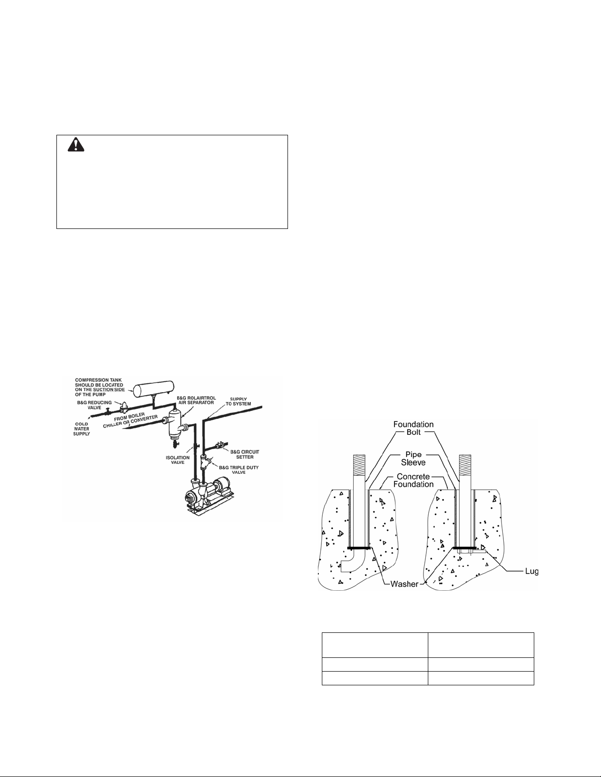
FOUNDATION
The concrete foundation or isolation pad must be
substantial enough to absorb vibration (Hydraulic
Institute Standards recommends that the
foundation weigh at least five times the weight of
the pump unit). It must form a permanent and rigid
support for the base plate and should be built to
suit local conditions. This is important in
maintaining the alignment of the flexibly coupled
unit. Do not use the base as the isolation pad.
Foundation bolts of the proper size should be
embedded in the concrete with either of the
methods shown in Figure 6. See Table 2 for
anchor bolt hole and anchor bolt sizes. Allow the
foundation to cure for several days before
proceeding with the pump installation.
Figure 5: Pump Location
The installation must be evaluated to
determine that the Net Positive Suction Head
Available (NPSHA) meets or exceeds the Net
Positive Suction Head Required (NPSHR), as
stated by the pump performance curve.
The pump must be primed before starting.
Whenever possible, the pump should be
located below the fluid level to facilitate
priming and ensure a steady flow of liquid.
This condition provides a positive suction
head on the pump. It may also be possible to
prime the pump by pressurizing the suction
vessel.
Figure 6: Foundation
Table 2: Anchor Bolt/Hole Sizes
Diameter of Anchor
Bolt Hole
Diameter of Anchor
Bolt
1.125” 1.000”
1.375” 1.250”
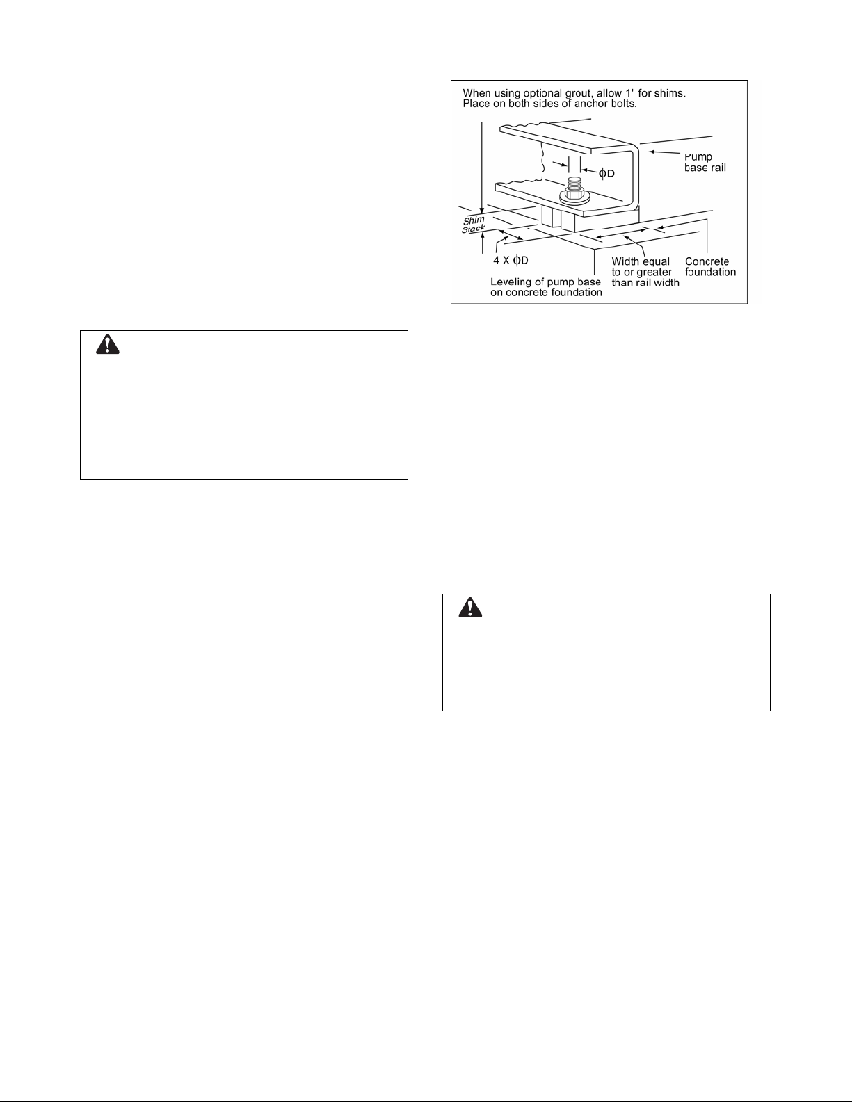
BASE PLATE SETTING
Place the pump unit on its concrete foundation,
supporting it with steel wedges or shims. The
wedges or shims should be machined and be put
on both sides of each anchor bolt to provide a
means for leveling the base. The wedge or shim
width should be equal to or greater than the base
rail width. The length of the wedge or shim should
be at least four times the diameter of the anchor
bolt. It is acceptable to place additional shims
between the existing anchor bolts.
Use an anchor bolt for each anchor bolt hole
provided, and plain, flat Type-W washers at each
anchor bolt.
CAUTION: Equipment Damage
Use an anchor bolt and plain, flat Type-W washer
at each anchor bolt hole. Otherwise, shifting of the
pump unit may occur.
Figure 7: Setting Base Plate
ROTATION
The Series VSX pump is available in both rightand left-hand rotation. An arrow cast into the pump
body shows the direction of rotation.
Failure to follow these instructions could result in
serious property damage and/or moderate
personal injury.
It is very important that the pump base be set level
to avoid any mechanical difficulties with the motor
or pump. This pump was properly aligned (if
furnished with a motor) at the factory. However,
since all pump bases are flexible, they may spring
and twist during shipment. Do not pipe the pump
until it is realigned. After piping is completed and
after the pump is installed and bolted down, align it
again. It may be necessary to re-adjust the
alignment from time to time while the unit and
foundation are new.
Optional Grouting
It is permissible to grout the base after the
pump unit has been leveled, securely bolted
to the floor, and properly aligned. A good
grade of non-shrinking grout should be used
inside the pump base.
COUPLING ALIGNMENT
All alignment should be done by moving or
shimming the motor only. Adjustments in one
direction may alter alignment in another.
Therefore, check alignment in all directions after a
correction is made. All measurements should be
taken with the pump and motor bolts tightened.
Final alignment check should be made after the
unit has attained its final operating temperature.
WARNING: Unexpected Startup Hazard
Disconnect and lockout power before servicing.
Failure to follow these instructions could result in
serious personal injury or death, or property
damage.
1. Check the pump and motor shafts and
remove any paint, burrs, rust, etc. Slide
the hubs (and bushings, QD or TaperLock style) on the shafts with keys.
2. When high speed rings are used for
spacer couplings, loosely install one ring
on each half element.
8
3. Hold one half element on the hubs to
determine the appropriate hub spacing. If
using spacer elements with high speed
rings, hold both half elements on the hubs
to make sure the hubs do not interfere
with the rings. The hubs may be installed
with the hub extension facing in or out.
Make sure the shaft extends into the hubs
at least .8 times the diameter of the shaft.
4. Lightly fasten the hubs to the shafts to
prevent them from moving during
alignment.
5. The hubs should be aligned to at least the
values shown in Figure 10 for allowable
misalignments. Alignment may be done
with lasers, dial indicators, or with a
straight edge and calipers.
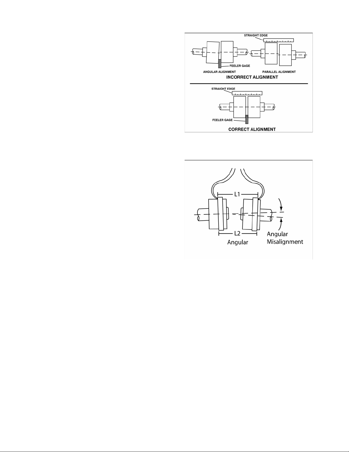
To align using straight edge and calipers
Angular misalignment may be checked by
using a caliper to gauge the distance
between the two hubs at various points
around the circumference. Do not rotate the
shafts. Reposition the equipment until the
difference between the minimum and
maximum distance values is within the
permissible value.
Figure 8: Checking Alignment with
Straight Edge
Angular misalignment may also be checked
by inserting feeler gauges between the
coupling faces at various points around the
circumference. Do not rotate the shafts.
Reposition the equipment until the difference
between the minimum and maximum
distance values is within the permissible
value.
Parallel alignment may be checked by placing
a straight edge across the two hubs and
measuring the maximum offset at various
points around the periphery of the hubs. Do
not rotate the shafts. Reposition equipment
until the offset is within the permissible value.
Figure 9: Checking Alignment with Calipers
9
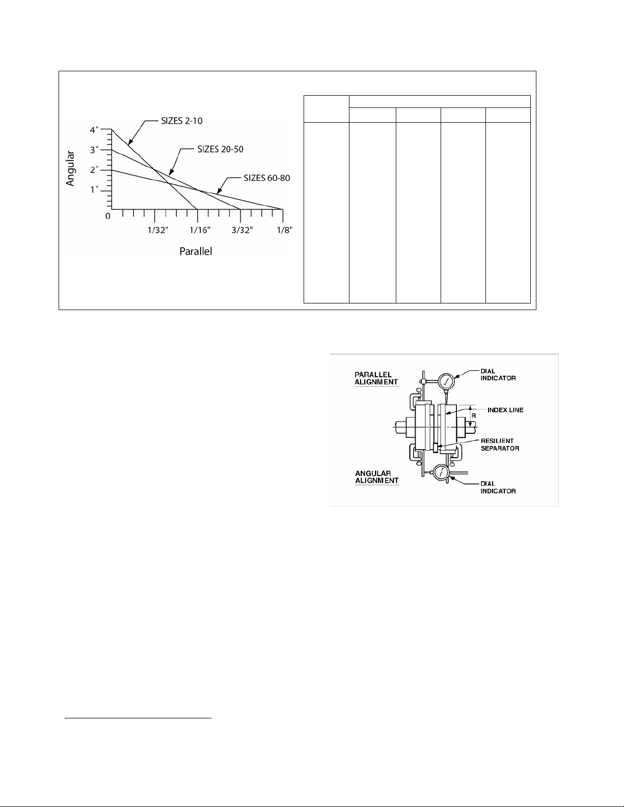
Figure 10: Maximum Allowable Misalignment for Wood’s Duraflex®1 Couplings
Example: A WE10 coupling with a 3° angular
misalignment will have a .191” difference in
measurements between L1 and L2. (See Figure
9.)
Table 3: Angular Inch Gap
Hub
Size
1 2 3 4
Degrees
WE2 0.032 0.065 0.097 0.129
WE3 0.040 0.081 0.121 0.162
WE4 0.045 0.091 0.136 0.181
WE5 0.055 0.109 0.164 0.218
WE10 0.064 0.127 0.191 0.218
WE20 0.078 0.156 0.234
WE30 0.095 0.189 0.284
WE40 0.116 0.231 0.347
WE50 0.142 0.284 0.425
WE60 0.153 0.305
WE70 0.161 0.323
WE80 0.196 0.393
To align using dial indicator
Angular misalignment may be checked by
mounting the dial indicator base to one
coupling half, or shaft, and positioning the dial
indicator button on the front face or rear face
of the opposite coupling half. Scribe index
lines on coupling halves as shown in Figure
11. Set the dial to zero. Rotate both coupling
halves together, making sure the index lines
remain matched. Reposition the equipment
until the offset is within the permissible value.
Parallel misalignment may be checked by
mounting the dial indicator base to one
coupling half, or shaft, and positioning the dial
indicator button on the outside diameter of
the opposite coupling half. Set the dial to
zero. Rotate both coupling halves together,
making sure the index lines remain matched.
Reposition the equipment until the offset is
within the permissible value.
Figure 11: Checking Alignment with
Dial Indicators
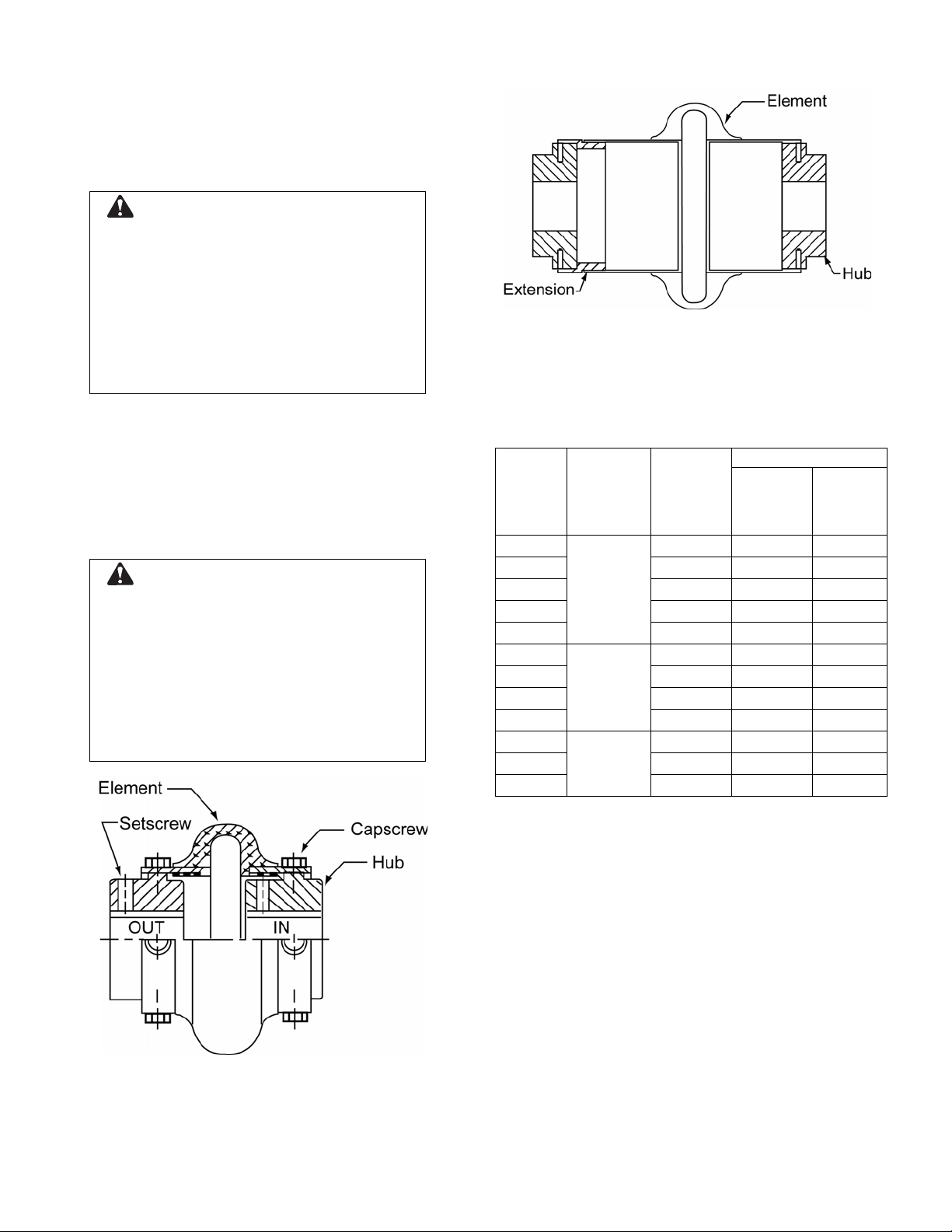
6. Recheck the hubs to be certain both
angular and parallel alignments are still
within the values given in Figure 10.
7. Loosen the set screw on the pump hub.
Loosely install one half element opposite
the hub set screws. Torque both hub set
screws to the value shown in Table 4. For
QD or Taper-Lock hubs, follow the
instructions supplied with the bushings.
Loosely install the other half element onto
the hubs. Install capscrews on the highspeed rings. If the capscrews and the
holes in the elements do not line up
1
Duraflex is a registered trademark of T.B. Wood’s, Inc.
10
properly due to hub misalignment, rotate
the shafts slightly. Torque all element and
high speed ring capscrews to the values
shown in Table 4. If possible, recheck
angular and parallel alignments.
WARNING: Flying Objects Hazard
Coupling capscrews and set screws are to be
installed using torque wrench or other torque
measuring device. Hardware not installed per
the listed torque values may become loose
and dislodge from coupling assembly.
Failure to follow these instructions could
result in serious personal injury or death, or
property damage.
8. Capscrews supplied with the coupling
have a thread lock coating that aids in
resisting loosening from vibration. The
capscrews should not be reused more
than four times or if the coating is absent.
Replacement capscrews are to be
purchased through your local Bell &
Gossett representative.
WARNING: Flying Objects Hazard
Capscrews with damaged or absent thread
lock coating should be not be used.
Otherwise the required counterforce will not
be achieved and hardware may become
loose and dislodge from coupling assembly.
Failure to follow these instructions could
result in serious personal injury or death, or
property damage.
Figure 13: Woods Duraflex Coupling
– Typical Spacer
Table 4: Fastener Torque Values and
Maximum RPM for Woods Duraflex
Couplings
Basic
Size
Element
& Ring
Capscrew
Torque
(ft-lb)
Standard
Hubs Set
screw
Torque
(ft-lb)
Maximum RPM
Standard Spacer
WE2 7 7500 1800
WE3 7 7500 1800
WE4 14 7500 1800
17
WE5 23 7500 1800
WE10
23 7500 1800
WE20 50 6600 1800
WE30 50 5800 1800
WE40 100 5000 1800
WE50
30
100 4200 1800
WE60 167 3800 1800
WE70 167 3600 1800
WE80
75
167 2000 1800
Figure 12: Woods Duraflex Coupling
– Typical Non-spacer
1
Final Alignment
Final alignment cannot be accomplished until
the pump as been operated initially for a
sufficient length of time to attain operating
temperature. When normal operating
temperature has been attained, secure the
pump to re-check alignment and compensate
for temperature accordingly. (See the section
entitled Coupling Alignment.)
NOTE: Elastomeric couplings are specifically
designed to accommodate angular shaft
misalignment, as well as parallel offset of the
pump and motor shafts. However, the amount
of the offset and/or misalignment is
dependent on the style of flexible coupling
applied. Left unchecked, coupling
misalignment has a significant impact on the
overall life of the mechanical seals and the
bearings of the pump.
WARNING: Rotating Components
Hazard
Do not operate pump without all guards in place.
Failure to follow these instructions could result in
serious personal injury or death, or property
damage.
SUCTION AND DISCHARGE PIPING
When installing piping, refer to the Hydraulics
Institute Standards and observe the following
precautions:
Where flanged joints are used, ensure that inside
diameters match properly.
Remove burrs and sharp edges when making up
joints.
Do not “spring” piping when making any
connections. Coupling and bearing wear will result
if the suction or discharge lines are forced into
position.
When considerable temperature changes are
anticipated, equipment for absorbing expansion
should be installed in the system in such a way as
to avoid strain on the pump.
When using an isolation pad, flexible piping should
also be used on both the suction and discharge
sides of the pump.
The pipeline should have isolation valves around
the pump and have a drain valve in the suction
pipe.
See Technical Bulletin B-876 or BX-876, Table 5
for allowable static flange loading for vertical
flange configuration. (Models VSC and VSCS)
A Bell & Gossett Triple Duty Valve installed in the
discharge line will serve as a check valve to
protect the pump from water hammer, as a gate
valve for servicing, and for throttling.
Piping should always be run to the pump.
Do not move pump to the pipe. This could make
final alignment impossible.
Both the suction and discharge piping should be
supported independently near the pump and
properly aligned so that no strain is transmitted to
the pump when the flange bolts are tightened. Use
pipe hangers or other supports at necessary
intervals to provide support. When expansion
joints are used in the piping system they must be
installed beyond the piping supports closest to the
pump. Tie bolts should be used with expansion
joints to prevent pipe strain. Do not install
expansion joints next to the pump or in any way
that would cause a strain on the pump resulting
from system pressure changes.
Install the piping as straight as possible, avoiding
unnecessary bends. Where necessary, use 45° or
long sweep 90° fittings to decrease friction losses.
Make sure that all piping joints are leak tight.
1
 Loading...