

Page 1
INSTRUCTION MANUAL
V59075B
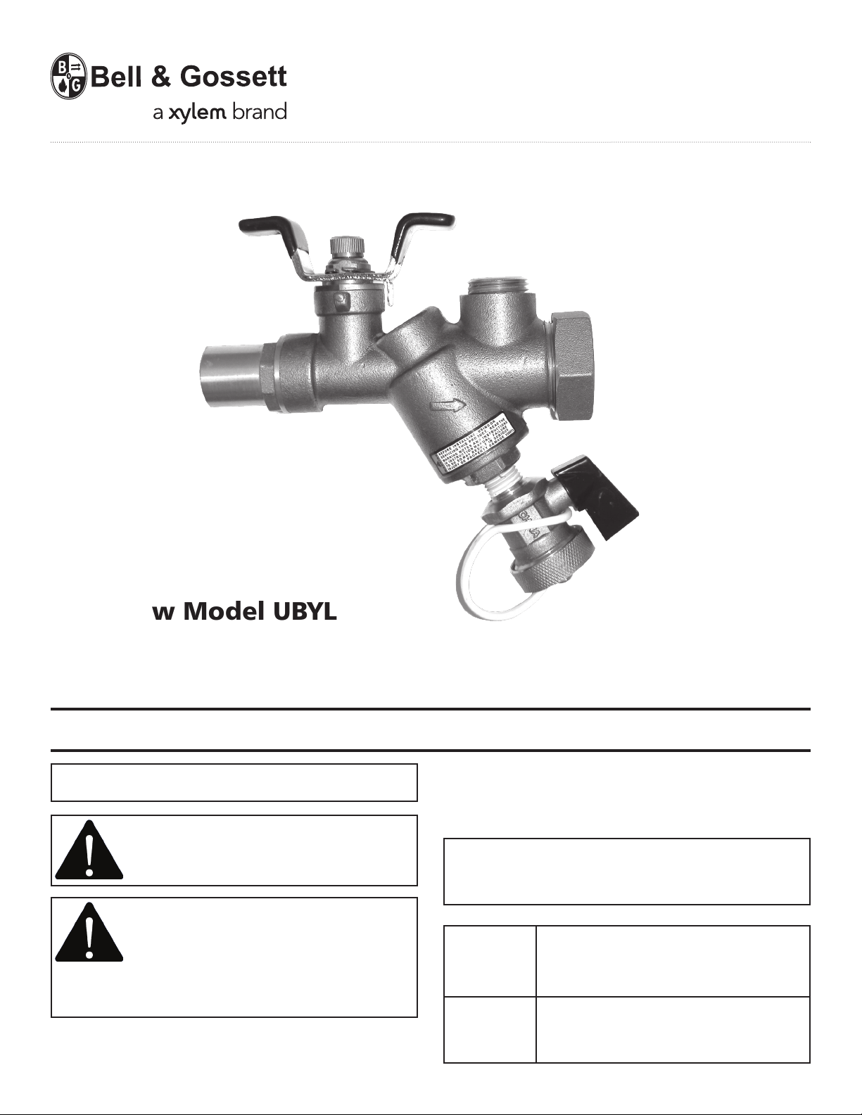
Low Flow Model UBYL
Y-Strainer Combination Valve
INSTALLER: PLEASE LEAVE THIS MANUAL FOR THE OWNER’S USE.
NOTE: This product is not intended for use in potable
water applications.
WARNING: This product may contain a
chemical known to the State of California
to cause cancer, or birth defects or other
reproductive harm.
This safety alert symbol will be used in
this manual to draw attention to safety
related instructions. When used, the
safety alert symbol means ATTENTION!
BECOME ALERT! YOUR SAFETY IS INVOLVED! FAILURE
TO FOLLOW THE INSTRUCTIONS MAY RESULT IN A
SAFETY HAZARD.
OPERATIONAL LIMITS
WORKING PRESSURE & TEMPERATURE LIMITS
(SOLDER TYPE LIMITS FOR ANSI STD. B.16.18)
COIL HOOKUP VALVE TEMP °F (°C) PRESSURE PSI (KPA)
Y-Strainer Valve (NPT) 250° (121°) 400° (2758°)
Y-Strainer Valve (sweat) Based on solder type ASTM Std.
B16.18
TYPE OF
SOLDER
95-5
TINANTIMONY
MAXIMUM LIMITATIONS 1/2” - 3/4”
PRESSURE
PSI (kPa)
300 (2069) 200° (93°)
250 (1724) 225° (107°)
200 (1379) 250° (121°)
TEMP
° F (° C)
Page 2
DESCRIPTION
Low Flow Y-strainer Valves are made of brass construction
with an integrated ball valve and strainer.
INSTALLATION INSTRUCTIONS
CAUTION: Heat associated with the use of
silver solder may damage valve components
and void the product warranty. Do not use
silver solder. Failure to follow these
instructions could result in property damage and/or
moderate personal injury.
Model UBYL Low Flow Y-strainer Valves are uni-directional
valves and should be mounted in the supply pipe. Be
sure to install the Model UBYL Low Flow Y-strainer valve
with the arrow pointing in the direction of flow and the
strainer chamber down to prevent air binding and to allow materials to collect in the strainer. Be sure to provide
enough space around the valve to remove the strainer
from the valve body for cleaning.
LOW FLOW MODEL UBYL Y-STRAINER VALVES
WITH SWEAT CONNECTIONS
For installing sweat connections:
a) Clean tube ends and valve connections thoroughly per
good piping practices with a fine grade emery cloth or
fine grit sandpaper.
b) For soldering, use 95-5 (Tin-Antimony) solder and a
good grade of flux.
c) Use a torch with a sharp pointed flame.
d) When sweating the joints, adjust the valve to the full
open position, then wrap the valve with a cool wet rag
and then direct the flame with care to avoid subjecting
the valve to excessive heat. Allow the valve to cool before
touching or operating.
e) Check the soldered connection for leaks.
WARNING: Use of improper procedures to
sweat valve model with union
connection into system can damage valve.
Before installing sweat union connection
to valve, remove the union nut and O-ring from the
valve body, then union tailpiece with union nut must
be sweated (soldered) into place. Failure to follow this
instruction could result in property damage and/or
moderate personal injury.
CAUTION: Excessive use of solder or flux
may result in damage to the shutoff valve
seat and ball. Do not use excessive solder or
flux. Failure to follow these instructions
can result in moderate personal injury and/or property
damage.
LOW FLOW MODEL UBYL Y-STRAINER VALVES
WITH NPT CONNECTIONS
Apply pipe compound conservatively to male connecting
fittings only. After installation, check all joints for
leakage and re-tighten if necessary.
CAUTION: The use of PTFE impregnated
pipe compound and PTFE tape on pipe
threads provides lubricity. Care should be
taken to prevent over tightening
which may damage the valve body. Failure to follow
these instructions can result in personal injury and/or
property damage.
OPERATION INSTRUCTIONS
HOW TO USE BELL & GOSSETT LOW FLOW
MODEL UBYL Y-STRAINER VALVES
Y-strainer can be used to isolate hydronic equipment for
repairs and/or to drain the system. To close the Y-strainer
ball valve, move the handle a quarter of a turn until the
handle is perpendicular to the valve and piping.
CAUTION: Hot un-insulated surfaces can
cause burns to the skin. Do not touch hot
surfaces. Failure to follow these instructions
could result in personal injury.
Page 3

Installed P/T Port
Isolation Valve
Strainer
Before system start up, flush the hydronic system as part
of commissioning. Make sure the valve cap and drain is
tightened properly. Start the system and inspect the Low
Flow Model UBYL Y-strainer valve for leakage.
HOW TO USE PRESSURE TAPS (P/T PORTS) TO MEASURE
SYSTEM OPERATING CONDITIONS
Using Bell & Gossett Model RP-250B, readout probes,
attach Bell & Gossett differential pressure readout kit to
the readout valves (P/T ports) on the Low Flow Model
UBYL Y-Strainer Valves.
WARNING: Hot water leakage can occur
from readout valves (P/T ports) during probe
insertion and during hookup of readout kit.
Follow the instruction manuals supplied
with readout probes and readout kits for safe use.
Failure to follow these instructions could result in
serious personal injury or death and property damage.
Read the differential pressure from the coil inlet
isolation valve (typically a strainer) to coil outlet
isolation valve (typically a flow limiting balancing valve).
The differential value minus the pressure drops across the
coil and installed control valves should be less than 60 psi
for proper flow control.
If Y-strainer pressure drop becomes excessive,
accumulated dirt and contaminants should be blown
through the blow-down line (if installed) to a drain. If a
blow-down line is not installed, see the service
instructions for removing and cleaning the strainer. The
Y-strainers have construction with an integrated ball valve
and will function as a service valve.
SERVICE INSTRUCTIONS
If excessive pressure drop is noted across the Y-Strainer,
the internal strainer has most likely collected a lot of dirt
or debris and needs to be cleaned. Install blow-down line
(hose) to the drain valve on the strainer chamber then
open the drain valve. If flushing the strainer at this point
has not solved the pressure drop problem, the Y-strainer
must be disassembled and strainer to be cleaned.
To clean the strainer, isolate the Y-Strainer from the
system with the integral ball valve on the upstream side
of the strainer. Use an isolation valve downstream of the
strainer and coil to further isolate the system. Allow the
system to cool to 100°F (38°C) or less before handling.
Proceed to drain the isolated system through the drain
valve in the Y-Strainer.
WARNING: Corrosion or leakage are
indications that the Low Flow Model UBYL
Y-Strainer Valve must be replaced. Failure to
follow these instructions could result in
serious personal injury or death and property damage.
Page 4

Remove the brass cap and drain valve on the Y-strainer.
Grab and remove the strainer. Clean the strainer in water
to remove collected dirt and debris. Check to make sure
that no other debris remains in the valve. Reinstall the
strainer and the valve cap with drain valve. Return
isolation valves to the open position. Pressurize the
system and vent any trapped air at the return side of the
system. Check for strainer cap leaks. If noted, slightly
tighten cap until leakage stops. Replace with a new
strainer (V58577) if necessary.
CAUTION: Make sure Valve Cap is properly
assembled. Failure to follow these
instructions can result in personal injury
and/or property damage.
Due to the different types of material used, the Low Flow
Model UBYL Y-Strainer Valve must be disassembled prior
to disposal. Special handling of certain valve components
may be required by law or may be sensible from an
ecological point of view.
INSULATION
Bell & Gossett recommends that insulation be attached
to Model UBYL Y-Strainer Combination Valve after the
system has been balanced.
NOTE: Tape or other acceptable means should be used to
secure the insulation to the Model UBYL Y-Strainer
Combination Valve.
Periodically inspect the Low Flow Model UBYL Y-Strainer
Valve for signs of leakage or corrosion. Replace valve cap
o-ring (V57754), if necessary.
WARNING: Corrosion or leakage are
indications that the Low Flow Model UBYL
Y-Strainer Valve must be replaced. Failure to
follow these instructions could result in
serious personal injury or death and property damage.
Patent Pending
Xylem Inc.
8200 N. Austin Avenue
Morton Grove, Illinois 60053
Phone: (847) 966-3700
Fax: (847) 965-8379
www.xyleminc.com/brands/bellgossett
Bell & Gossett is a trademark of Xylem Inc. or one of its subsidiaries.
© 2012 Xylem Inc. V59075B September 2012
 Loading...