

Page 1
INSTRUCTION MANUAL
V59074B
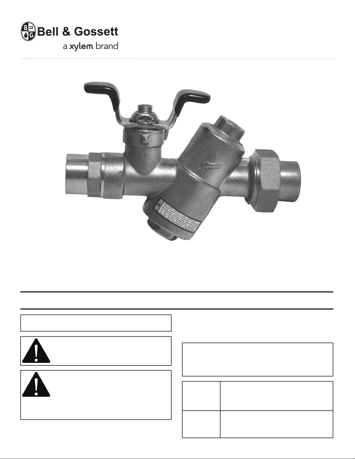
Low Flow Circuit Sentry
Model ACL Flow Limiting Valves
INSTALLER: PLEASE LEAVE THIS MANUAL FOR THE OWNER’S USE.
NOTE: This product is not intended for use in potable
water applications.
WARNING: This product may contain a
chemical known to the State of California
to cause cancer, or birth defects or other
reproductive harm.
SAFETY INSTRUCTION: This safety alert
symbol will be used in this manual to draw
attention to safety related instructions.
When used, the safety alert symbol means
ATTENTION! BECOME ALERT! YOUR SAFETY IS
INVOLVED! FAILURE TO FOLLOW THE INSTRUCTIONS
MAY RESULT IN A SAFETY HAZARD.
OPERATIONAL LIMITS
WORKING PRESSURE & TEMPERATURE LIMITS
(SOLDER TYPE LIMITS FOR ANSI STD. B.16.18)
COIL HOOKUP VALVE TEMP °F (°C) PRESSURE PSI (KPA)
Union Ended Ball
Valve (NPT) 250° (121°) 400° (2758°)
Union Ended Ball Based on solder type ASTM Std.
Valve (sweat) B16.18
TYPE OF
SOLDER
95-5
TINANTIMONY
MAXIMUM LIMITATIONS 1/2” - 3/4”
PRESSURE
PSI (kPa)
300 (2069) 200° (93°)
250 (1724) 225° (107°)
200 (1379) 250° (121°)
TEMP
° F (° C)
Page 2
DESCRIPTION
Low Flow Circuit Sentry Model ACL valve is designed to
automatically control the flow in piping systems to a
selected preset limit. As pressure differential increases, a
cartridge inside the valve body reduces the flow area to
accurately maintain the preselected flow rate.
CAUTION: Heat associated with the use of
silver solder may damage valve components
and void the product warranty. Do not use
silver solder. Failure to follow these
instructions could result in property damage and/or
moderate personal injury.
Flow Operating Range: 0.25 – 3.8 GPM
INSTALLATION INSTRUCTIONS
Low Flow Circuit Sentry Model ACL Flow Limiting Valves
are uni-directional valves and can be installed in most
orientations; Low Flow Circuit Sentry valves should be
mounted in the return pipe where temperatures are
lower and where the sealing gland is less affected by pipe
strain. Installation of strainers and isolation ball valves
is recommended. Be sure to install the Low Flow Circuit
Sentry ACL valve with the arrow pointing in the
direction of flow. Provide enough space around the
valve to ensure the flow cartridge can be removed for
flow adjustment or system commissioning.
LOW FLOW CIRCUIT SENTRY MODEL ACL VALVES
WITH SWEAT CONNECTIONS
For installing sweat connections, make sure that the flow
limiting cartridge has not yet been installed in the valve.
When confirmed, proceed as follows:
a) Clean tube ends and valve connections thoroughly per
good piping practices with a fine grade emery cloth or
fine grit sandpaper.
CAUTION: Excessive use of solder or flux
may result in damage to the shutoff valve
seat and ball. Do not use excessive solder or
flux. Failure to follow these instructions can
result in moderate personal injury and/or property
damage.
LOW FLOW CIRCUIT SENTRY MODEL ACL VALVES
WITH NPT CONNECTIONS
Apply pipe compound conservatively to male connecting
fittings only. After installation, check all the joints for
leakage and re-tighten if necessary.
CAUTION: The use of PTFE impregnated
pipe compound and PTFE tape on pipe
threads provides lubricity. Care should be
taken to prevent over tightening which may
damage the valve body. Failure to follow these
instructions can result in personal injury and/or
property damage.
LOW FLOW CIRCUIT SENTRY MODEL ACL VALVES
FLOW LIMITING CARTRIDGE INSTALLATION
b) For soldering, use 95-5 (Tin-Antimony) solder and a
good grade of flux.
c) Use a torch with a sharp pointed flame.
d) When sweating the joints, adjust the valve to the full
open position, then wrap the valve with a cool wet rag
and then direct the flame with care to avoid subjecting
the valve to excessive heat. Allow the valve to cool before
touching or operating.
e) Check the soldered connection for leaks.
WARNING: Use of improper procedures to
sweat valve model with union connection
into system can damage valve. Before
installing sweat union connection to valve,
remove the union nut and O-ring from the valve body,
then union tailpiece with union nut must be sweated
(soldered) into place. Failure to follow these
instructions could result in property damage and/or
moderate personal injury.
Page 3

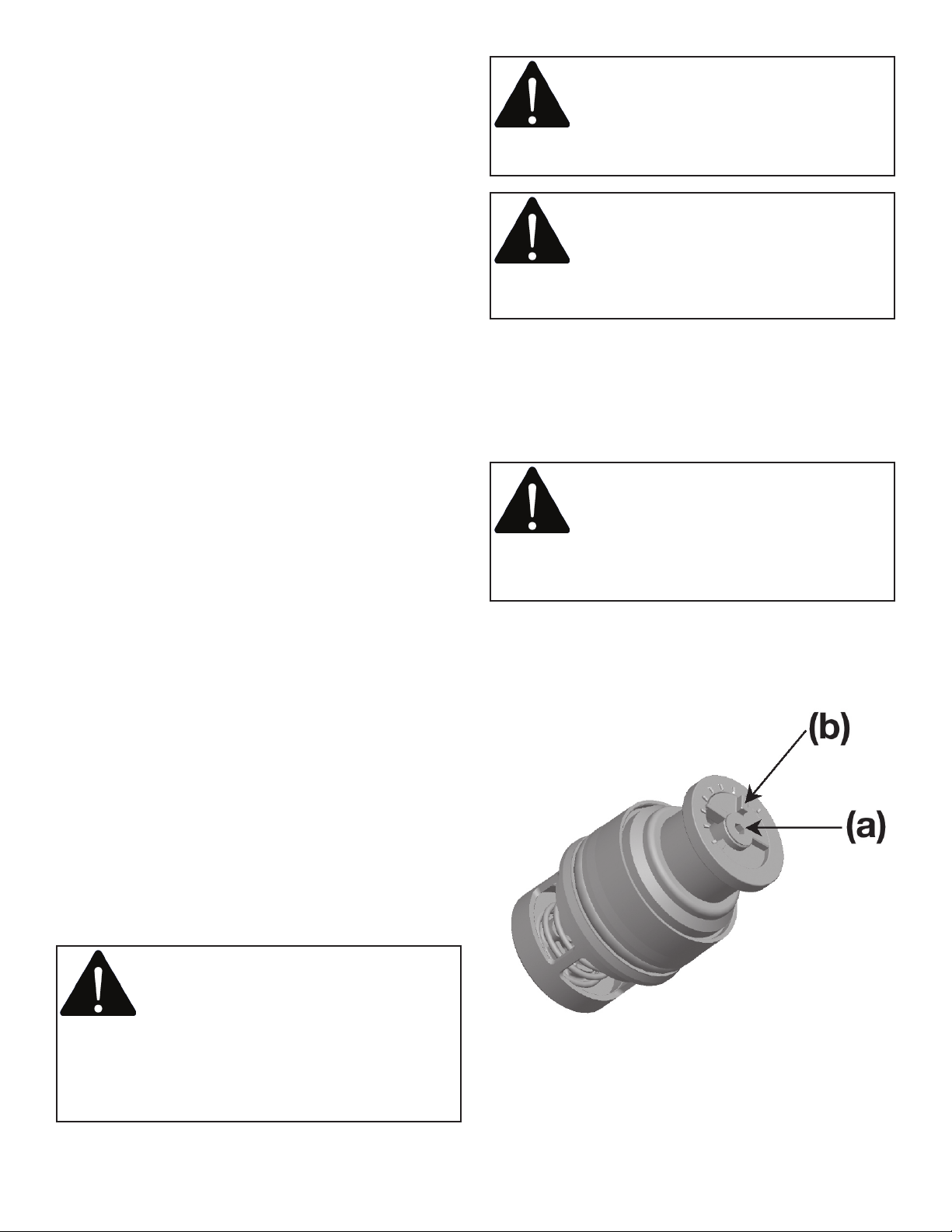
Prior to coil commissioning and operating the Flow
Limiting Valve, adjust cartridge to the desired flow rate
between 0.25 GPM to 3.8 GPM.
1. Loosen screw (a) position.
2. Rotate plastic dial (b) to the desired flow rate.
Increments marked on variable orifice are in GPM.
3. Re-tighten screw (a) with dial set at the desired
flow rate.
4. Install the cartridge as shown below.
Installed P/T Port (A)
Isolation Valve
Flow Cartridge
Optional P/T
Port (B)
Before system start up, remove the flow limiting cartridge
from the valve, if previously installed. Flush the hydronic
system as part of commissioning and then reassemble
cartridge into the valve. Make sure the valve cap is
tightened properly. Start the system and inspect the Low
Flow Circuit Sentry ACL valve for leakage.
HOW TO USE PRESSURE TAPS (P/T PORTS) TO MEASURE
SYSTEM OPERATING CONDITIONS
Using Bell & Gossett Model RP-250B, readout probes,
attach Bell & Gossett differential pressure readout kit to
the readout valves (P/T ports) on the Low Flow Circuit
Sentry ACL valve.
WARNING: Hot water leakage can occur
from readout valves (P/T ports) during probe
insertion and during hookup of readout kit.
Follow the instruction manuals supplied
with readout probes and readout kits for safe use.
Failure to follow these instructions could result in
serious personal injury or death and property damage.
Read the differential pressure from the coil inlet
isolation valve (typically strainer) to coil isolation valve
(typically a flow limiting balancing valve). The
differential value minus the pressure drops across the coil
and installed control valves should be less than 60 psi for
proper flow control.
If more accurate readings are desired, a pressure readout
valve (B&G P/N V58050) may be installed (B) in the barrel
above the cartridge chamber of the flow limiting valve.
Pressure readings should then be taken from the P/T valve
located in the isolation valve (A) and the P/T valve located
in the barrel of the cartridge (B). The differential valve
should be less than 60 psi for proper control.
CAUTION: Make sure Valve Cap is properly
assembled. Failure to follow these
instructions can result in personal injury and/
or property damage.
OPERATION INSTRUCTIONS
HOW TO USE BELL & GOSSETT LOW FLOW CIRCUIT
SENTRY MODEL ACL FLOW LIMITING VALVES FOR
PRE-SET FLOW BALANCING
Operation of the Flow Limiting Valve is fully automatic.
It automatically maintains the selected flow over the
designed differential pressure range.
CAUTION: Hot un-insulated surfaces can
cause burns to the skin. Do not touch hot
surfaces. Failure to follow these instructions
could result in personal injury.
SERVICE INSTRUCTIONS
Periodically inspect the Low Flow Circuit Sentry Model
ACL Flow Limiting Valve for signs of leakage or corrosion.
Replace valve cap o-ring (V57754), if necessary
WARNING: Corrosion or leakage are
indications that the Low Flow Circuit Sentry
Model ACL Flow Limiting Valve must be
replaced. Failure to follow these
instructions could result in serious personal injury or
death and property damage.
Due to the different types of material used, the Low Flow
Circuit Sentry Model ACL Flow Limiting Valve must be
disassembled prior to disposal. Special handling of
certain valve components may be required by law or may
be sensible from an ecological point of view.
Page 4

Should the Flow Limiting Valve require cleaning or
changing the flow rate, follow the instructions below:
1. Loosen and remove the cap from the valve body.
2. Pull the cartridge assembly from the valve body
for cleaning or flow adjustment.
3. Check the cartridge by pushing the orifice washer
into the cartridge housing several times to make
sure spring is functional and to dislodge any
possible debris. Rinse with water if necessary.
4. Once clean, return flow cartridge to valve
following installation instructions above.
5. Replace with a new flow cartridge (V58564) if
necessary.
INSULATION
Bell & Gossett recommends that insulation be attached
to the Low Flow Circuit Sentry Model ACL Flow Limiting
Valve after the system has been balanced.
NOTE: Tape or other acceptable means should be used
to secure the insulation to the Low Flow Circuit Sentry
Model ACL Flow Limiting Valve.
Patent Pending
Xylem Inc.
8200 N. Austin Avenue
Morton Grove, Illinois 60053
Phone: (847) 966-3700
Fax: (847) 965-8379
www.xyleminc.com/brands/bellgossett
Bell & Gossett is a trademark of Xylem Inc. or one of its subsidiaries.
© 2012 Xylem Inc. V59074B September 2012
 Loading...