

Page 1
INSTRUCTION MANUAL
V58912B
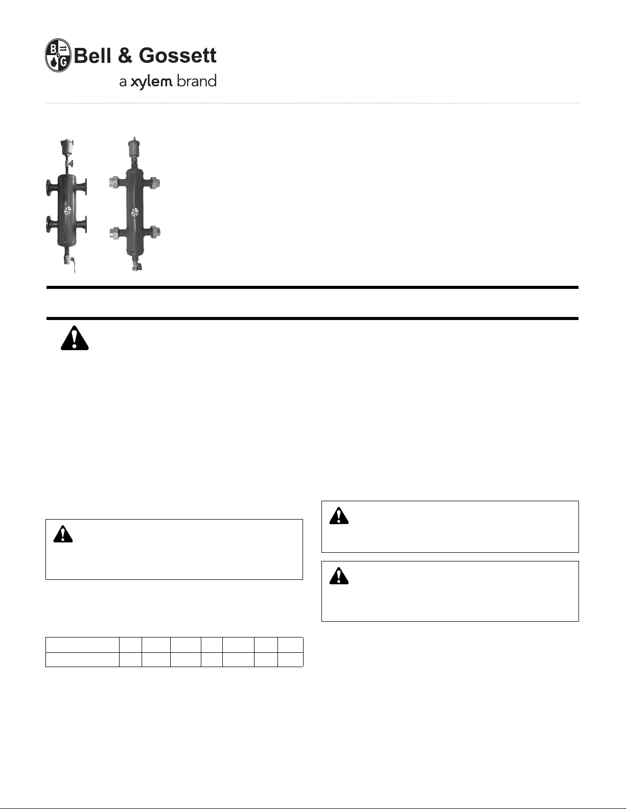
PSH
Primary-Secondary Header
Flanged & Threaded Connections
INSTALLER: PLEASE LEAVE THIS MANUAL FOR THE OWNER’S USE.
SAFETY
INSTRUCTION
This safety alert symbol will be used in this manual to draw
attention to safety related instructions. When used, the safety
alert symbol means ATTENTION! BECOME ALERT! YOUR
SAFETY IS INVOLVED! FAILURE TO FOLLOW THESE INSTRUCTIONS MAY RESULT IN A SAFETY HAZARD.
DESCRIPTION
The Bell & Gossett’s PSH is a device which makes the primary
and secondary circuits connected to it independent and can
be used on hot or chilled water systems.
The PSH is supplied with an air-vent and check valve assembly to permit automatic discharge of the air in the circuits. The
PSH is also equipped with a drain valve for removing any
impurities deposited in the bottom of the unit.
WARNING: State of California Residents
This product contains a chemical known by the State
of California to cause cancer. This product contains a
chemical known by the State of California to cause birth
defects or other reproductive harm.
The PSH should be sized according to the maximum flow rate
at the inlet. The selected value must be either that of the primary circuit or of the secondary, whichever is the greatest.
TECHNICAL SPECIFICATIONS
Threaded Connections: 1", 1-1/4", 1-1/2" FNPT with Unions
Flanged Connections: 2", 2-1/2", 3" & 4" ANSI150 CLASS
Materials: Body: Steel
Air Vent: Brass
Drain Valve: Brass
Insulation – Threaded: PEX
Insulation – Flanged: Polyurethane Foam
Medium: water, glycol solution non-hazardous, therefore
excluded from the guidelines of 67/548/EC Directive
Maximum Percentage of Glycol: 30% Threaded
50% Flanged
INSTALLATION INSTRUCTIONS
CAUTION: All work must be performed by qualified
personnel trained in the proper application, installation, and maintenance of systems in accordance with all
applicable codes and ordinances.
WARNING: System fluids are under pressure or temp-
erature can be hazardous. Be sure the pressure has
been reduced to zero and the system temperature is below
100°F (38°C). Failure to follow these instructions could
result in property damage and/or personal injury.
Connection Size 1" 1-1/4" 1-1/2" 2" 2-1/2" 3" 4"
Flow Rate (gpm) 11 18 26 40 80 124 247
OPERATING DATA
With Insulation
Working Pressure: 150 psi
Operating Temperature – Threaded: 32°-210°F
Operating Temperature – Flanged: 32°-220°F
Without Insulation
Working Pressure: 150 psi
Operating Temperature – Threaded and Flanged: 32°-230°F
The hydraulic separator is installed between the primary and
secondary circuits, always in a vertical position.
Make sure that all connections are water-tight.
When making the water connections, take care not to overtighten the connections to the reducer. Failure to follow these
instructions could result in property damage and/or personal
injury.
During the installation, commissioning and maintenance of
hydraulic separators, all necessary steps should be taken to ensure that system water temperature does not cause danger to
people.
Page 2
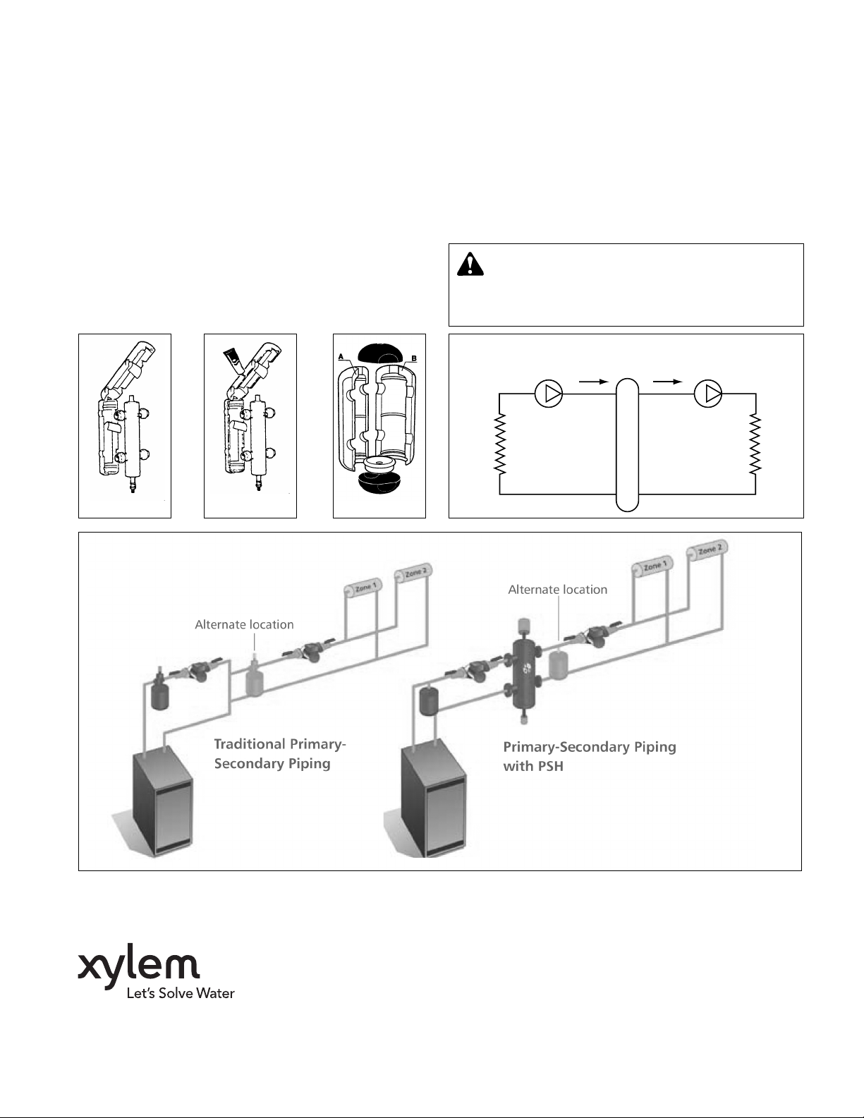
Procedure for installation and insulation
assembly on threaded models
1. Remove the protective strip from the adhesive surface. Reclose the shells (See Illustration A).
2. If the hydraulic separator is used with chilled water spread
a thin layer of sealant on the edge of the insulation and
wait until the solvent evaporates (10 minutes approx.) and
then close it again (See Illustration B).
Procedure for installation and insulation
assembly on flanged models (up to 4")
1. Remove the two black head covers at the ends.
2. Open the two side sections and the lower cap.
3. Install the separator in the system.
4. Use the tape provided on insulation.
5. Reassemble the two side sections, fitting the lower cap
into one of the two sections and then connecting the other.
6. Finish the assembly with the adhesive tape provided in the
box.
7. Complete with the two black head covers.
8. Fit the automatic air vent and the drain valve.
Recommended sealant: Superclear mastic.
SERVICE INSTRUCTIONS
There is no service required for the PSH.
CAUTION: Corrosion or leakage of the PSH can cause
damage or injury. Periodically inspect the PSH for
signs of leakage or corrosion. If noted, PSH must be
replaced. Failure to follow these instructions could result in
property damage and/or moderate personal injury.
Illustration A Illustration B Illustration C
primary
circuit
Primary
Circuit
Flow
Secondary
Circuit
Flow
secondary
circuit
Xylem Inc.
8200 N. Austin Avenue
Morton Grove, Illinois 60053
Phone: (847) 966-3700
Fax: (847) 965-8379
www.xyleminc.com/brands/bellgossett
Bell & Gossett is a trademark of Xylem Inc. or one of its subsidiaries.
© 2012 Xylem Inc. V58912B May 2012
 Loading...