

Bell & Gossett V58911B User Manual
INSTRUCTION MANUAL
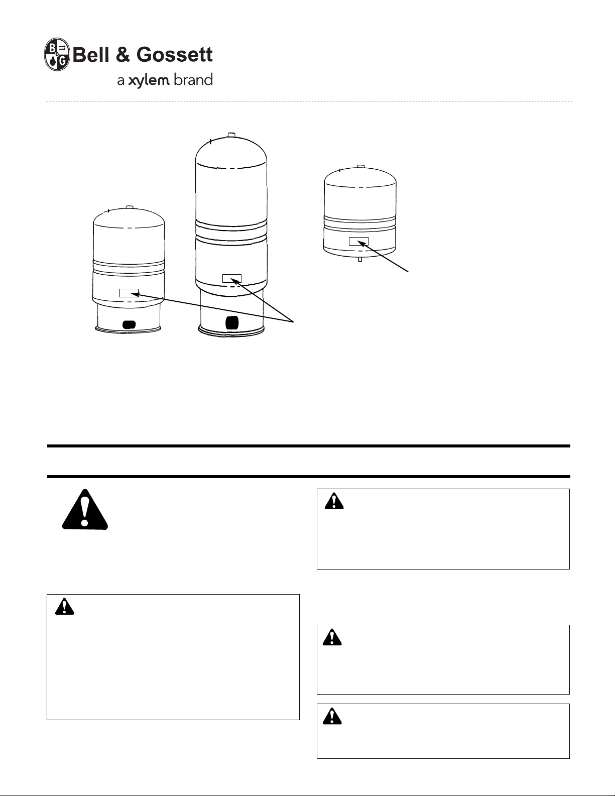
WARNING: Label Part No. 9017-078
must be installed in this location.
If missing, it must be replaced.
WARNING: Label Part No. 9015-463
must be installed in this location.
If missing, it must be replaced.
V58911B
Expansion Tanks for
Hydronic Heating Systems
INSTALLER: PLEASE LEAVE THIS MANUAL FOR THE OWNER’S USE.
WARNING: Read carefully the product installation, operating
and maintenance instructions. Failure to follow the instruc-
SAFETY
INSTRUCTION
This safety alert symbol will be used in this manual to draw attention
to safety related instructions. When used, the safety alert symbol means
ATTENTION! BECOME ALERT! YOUR SAFETY IS INVOLVED!
FAILURE TO FOLLOW THESE INSTRUCTIONS MAY RESULT IN A
SAFETY HAZARD.
WARNING: Explosion or Rupture Hazard.
A relief valve must be installed to prevent pressure in excess
of local code requirement or maximum working pressure
designated in the Product Manual, whichever is less. Do not expose
Product to freezing temperatures or temperatures in excess of
240°F. Do not adjust the pre-charge or re-charge this Product
except for any adjustments at the time of the initial installation,
especially if Product is corroded, damaged or with diminished
integrity. Adjustments to pre-charge must be done at ambient
temperature only. Failure to properly size the Product or follow
these instructions may result in excessive strain on the system and
may lead to Product failure, serious or fatal personal injury, leakage,
and/or property damage.
tions and warnings in the manual may result in serious or fatal
injury and/or property damage, and will void the product warranty.
This product must be installed by a qualified professional. Follow
all applicable local and state codes and regulations, in the absence
of such codes, follow the current editions of the National Plumbing
Code and National Electric Code, as applicable.
DESCRIPTION
The Series “HFT” tank is designed to absorb the expansion force in
heating water and maintain proper pressurization in a closed hydronic
system. The Series “HFT” tank is not for use in potable water systems.
WARNING: Series HFT Tanks are Not For Use in
Potable or fresh water can cause serious corrosion in Series HFT
tanks. This can result in leakage and a potential explosion. Do not
use HFT tanks for potable or fresh water applications. Failure to
follow this instruction will result in serious personal injury or death
and property damage.
WARNING: Potable Water
Danger: This Product must not be used in potable water or
open systems of any kind. These systems contain oxygenated
water that will cause internal corrosion and premature failure. Use
PT and PTA for potable water.
Potable Water Systems
OPERATIONAL LIMITS
Maximum Operating Pressure: 100 PSI.
Maximum Operating Temperature: 240ºF.
INSTALLATION INSTRUCTIONS
A. Pre-Installation
1. Visually inspect expansion tank and check for damage prior to
installation.
2. HFT tanks are factory precharged to 12 PSI, adjust pre-charge
to equal system fill pressure.
3. Replace and tighten plastic cap on air fitting.
B. Installation
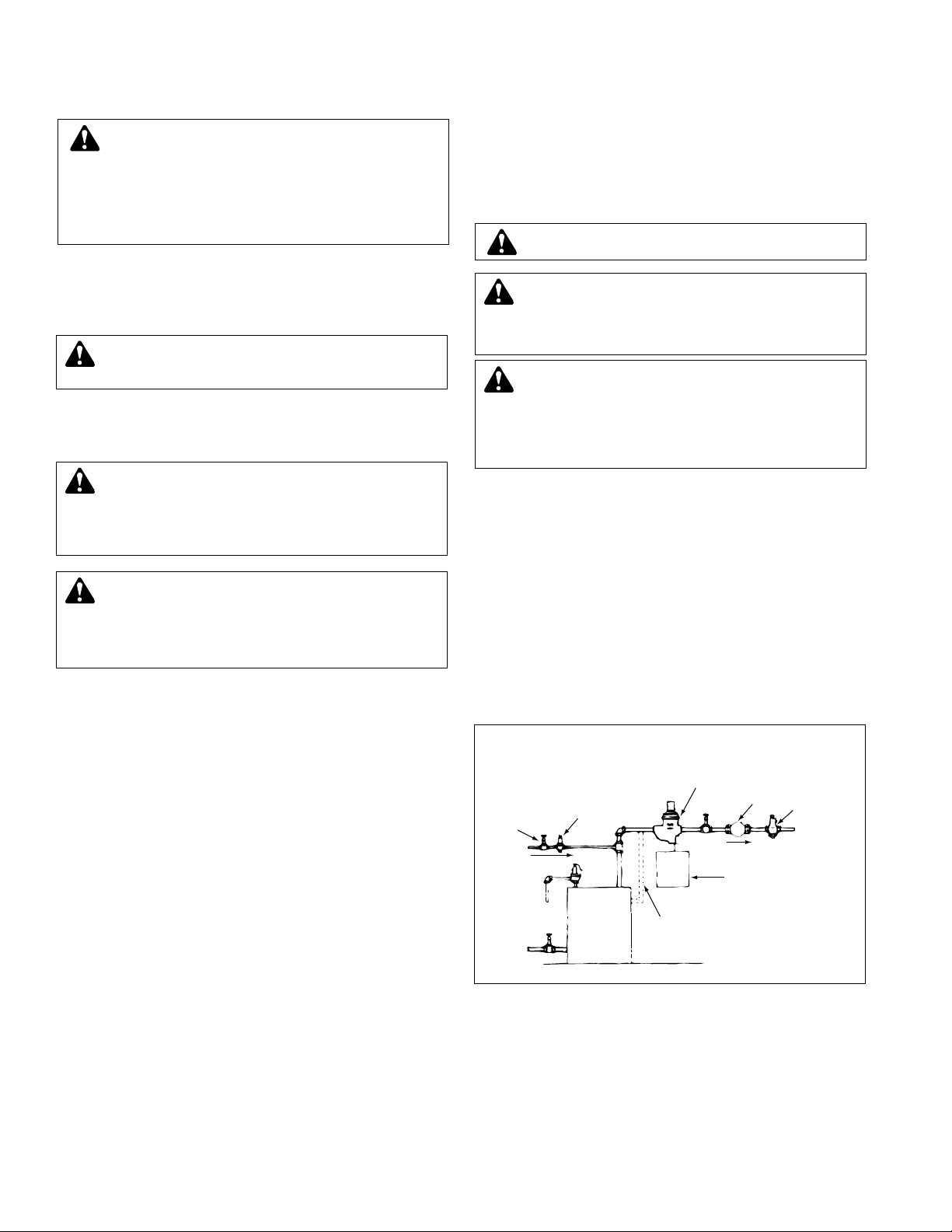
The Series “HFT” may be installed into a tee or any other suitable
tapping on a water heating system, on the suction side of the circulator. (see Figure 2).
It must be placed in a vertical position. It may also be remotely
located and piped to convenient point on the system. Do not install on
a dead end pipe or in an overhead joist space.
An ideal HFT tank installation is to screw it into the bottom of B&G air
separator (IAS, EAS or EASB-JR) located on the supply line. This
combination offers both control of expanded water and continuous
automatic air removal from the system.
After installing HFT tanks on the system:
1. Fill system.
2. Vent air from the system.
3. Bring system up to maximum operating temperature.
4. If an HFT tank is used with a volume smaller than required to
accommodate expanded water from a cold start to maximum
operating temperature, some preliminary expanded water must be
drawn from system to bring operating pressure down to normal
level. Drain water from boiler until pressure reads at maximum
range (25 PSIG).
Generally a smaller tank will cause a higher system pressure than
desired when system reaches operating temperatures. This
condition is normally referred to as a summer/winter installation
(boiler is always at temperature). Tank should be tagged to denote
this.
SYSTEM VENTING AND PURGING
After initial venting and purging of air from the system, more air will be
released from the water as it is heated. Therefore, it is recommended
that a B&G air separator be installed on the main.
If the system has multiple loops or zones, the supply water for all
loops and zones must pass through the air separator for complete and
continuous air removal. In case the piping arrangement does not
permit the installation of a single air separator on the main, air
separators should be installed on each loop or zone. In this event, only
one expansion tank is required for the system.
Even with a B&G air separator installed on the main or mains, it is
recommended that B&G air vents be installed on high points in the
system.
It is also recommended that a manual (key or coin type) air vents be
installed at higher points on the radiation.
WARNING: Rupture or Explosion Hazard
Like most pressurized tanks, this tank can over time
corrode, weaken, and burst or explode. Failure to follow this
instruction may result in serious personal injury or death and
property damage.
WARNING: Chlorine & Aggressive Water Warning
The water quality can significantly influence the life of your
product. You should test for corrosive elements, acidity, total
solids, and other relevant contaminants, including chlorine and
treat your water appropriately to insure satisfactory performance
and prevent premature failure. Failure to follow this instruction may
result in serious personal injury or death and property damage.
SHUT-OFF
VALVE
C.W. FILL
B&G RELIEF
VALVE
RETURN
BOILER
OPTIONAL
SIDE OUTLET
BOILER
CONNECTION
B&G PRESSURE
REDUCING VALVE
AIR SEPARATOR
B&G
BOOSTER
B&G
FLO-CONTROL
VALVE
TO
SYSTEM
DIAPHRAGM TYPE
EXPANSION TANK
“HFT”
FLOW
FIGURE 2
WARNING: CALIFORNIA PROPOSITION 65 WARNING!
Warning: This product contains a chemical known by the
State of California to cause cancer and to cause birth defects or
other reproductive harm. (California Installer/Contractor – California
law requires that this notice be given to consumer/end user of this
product.)
WARNING: System fluid under pressure and/or at high tem-
peratures can be very hazardous. Before servicing, reduce
system pressure to zero or isolate the vessel from the system.
Allow system to cool below 100°F and above 35°F. Failure to follow
this instruction may result in serious personal injury and/or property
damage.
WARNING: If the expansion tank is damaged, it must be
replaced. Failure to follow this instruction may result in
serious personal injury or death and property damage.
WARNING: This product, like most products under pressure,
may over time corrode, weaken and burst or explode,
causing serious or fatal personal injury, leaking or flooding and/or
property damage. To minimize risk, a licensed professional must
install and periodically inspect and service the Product. A drip pan
connected to an adequate drain must be installed if leaking or
flooding could cause property damage. Do not locate in an area
where leaking could cause property damage.
WARNING: Mount vertically only. Do not mount on deadend pipe.
 Loading...