

Page 1
Bell & Gossett
Instruction Manual V58766
WARNING: Label Part No. V56873
installed in this location (under
Bell & Gossett). If missing it must
be replaced.
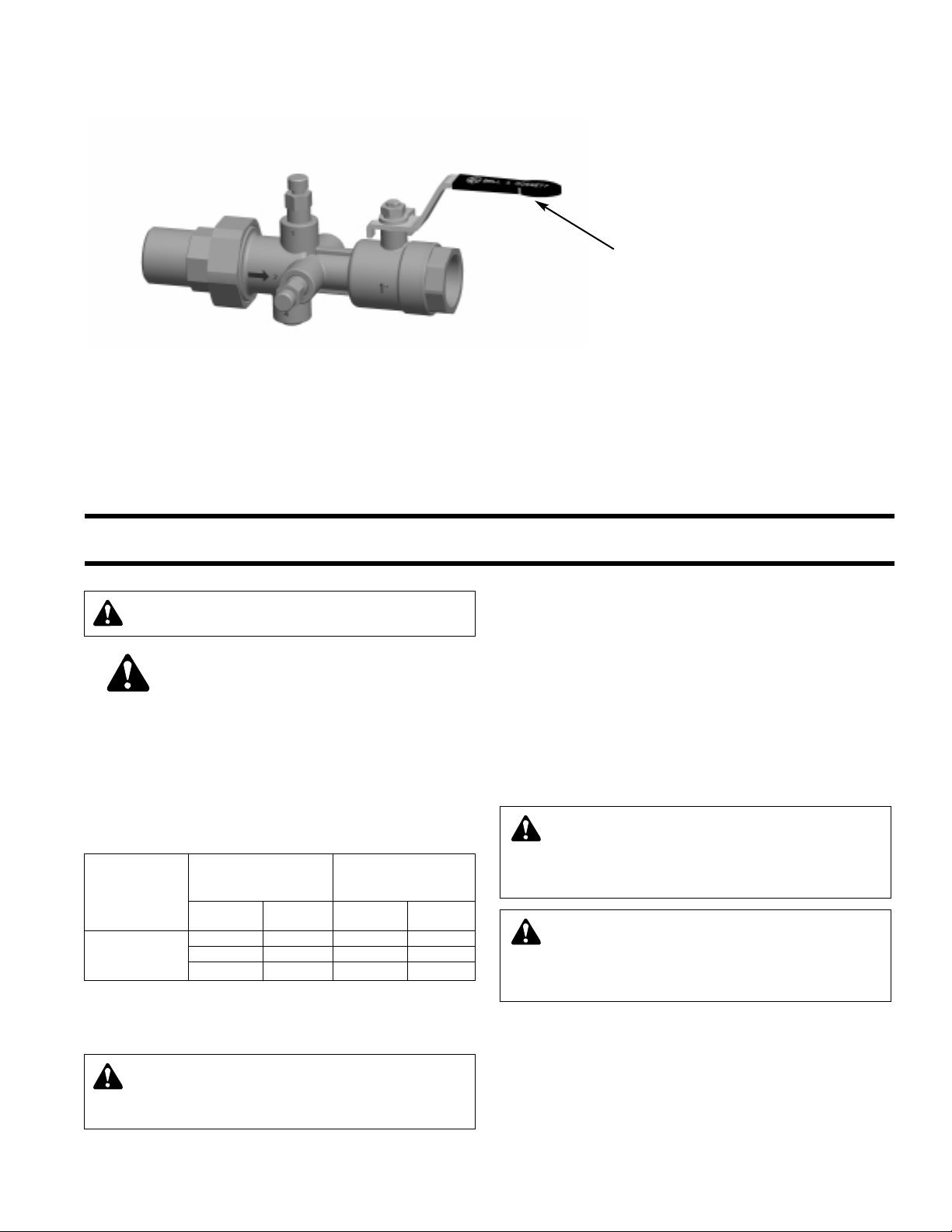
Triple Duty Valve
Model 3DV
Installation, Operation and Service Instructions
INSTALLER: PLEASE LEAVE THIS MANUAL FOR THE OWNER’S USE.
NOTE: Bell & Gossett does not recommend 3D
Valves to be used for potable water.
SAFETY
INSTRUCTION
This safety alert symbol will be used in this manual to draw
attention to safety related instructions. When used, the safety
alert symbol means ATTENTION! BECOME ALERT! YOUR
SAFETY IS INVOLVED! FAILURE TO FOLLOW THESE INSTRUCTIONS MAY RESULT IN A SAFETY HAZARD.
OPERATIONAL LIMITS
WORKING PRESSURE & TEMPERATURE LIMITS
(SOLDER TYPE LIMITS FOR ANSI STD. B.16.18)
MAXIMUM MAXIMUM
LIMITATIONS LIMITATIONS
TYPE OF 1/2" – 1" 11/4" – 2"
SOLDER PRESSURE TEMP PRESSURE TEMP
PSI (kPa) °F (°C) PSI (kPa) °F (°C)
95-5 300 (2069) 200 (93) 300 (2069) 175 (79)
TIN- 250 (1724) 225 (107) 250 (1724) 200 (93)
ANTIMONY 200 (1379) 250 (121) 175 (1207) 250 (121)
NPT
Maximum Operating Pressure 150 psig (1034 kPa)
Maximum Operating Temperature 250°F (121°C)
CAUTION: All work must be performed by qualified
personnel trained in the proper application, installation, and maintenance of systems in accordance with all
applicable codes and ordinances.
DESCRIPTION
The Bell & Gossett Model 3DV is a combination calibrated
balance, commissioning and positive shutoff valve for use in
HVAC systems. An efficient brass venturi design provides
accurate flow balancing with minimal system pressure loss.
Valves are furnished with two readout ports for pressure and
temperature, two optional
with memory stop, and a hanging ID tag for commissioning. A
variety of end connections are available on both the fixed and
union ends for sizes 1", 1
The 3DV provides highly accurate flow measurement
capabilities.
WARNING: Damage to the 3DV or failure of solder
sealing joints may occur it these operational limits are
exceeded. This can result in water leakage. Failure to follow this instruction can cause serious personal injury
and/or property damage.
WARNING: California Prop 65 Warning
This product contains a chemical known by the State
of California to cause cancer. This product contains a
chemical known by the State of California to cause birth
defects or other reproductive harm.
1
/4" ports, a standard port ball valve
1
/4", 11/2" and 2".
INSTALLATION INSTRUCTIONS
1. For installing Sweat Connections:
a) Clean tube ends and valve connections thoroughly per
good piping practices with a fine grade emery cloth or
fine grit sandpaper.
b) For soldering, use 95-5 (Tin-Antimony) solder and a
good grade of flux.
c) Use a torch with a sharp pointed flame.
Page 2
d) When sweating the joints, first adjust the valve in the full
open position, then wrap the valve with a cool wet rag
and then direct the flame with care to avoid subjecting
the valve to excessive heat. Allow the valve to cool
before touching or operating.
e) Check the soldered connection for leaks.
CAUTION: Excessive use of solder in a vertical instal-
lation may result in damage to the valve seat and ball.
Do not use excessive flux. Failure to follow these instructions could result in property damage and/or moderate
personal injury.
WARNING: Use of improper procedures to sweat
valve model with union connection into system can
damage valve. Before installing sweat union connection to
valve, remove the union nut and O-ring from the valve
body, then union tailpiece with union nut must be sweated
(soldered) into place. Failure to follow this instruction could
result in property damage and/or moderate personal injury.
CAUTION: Heat Associated with the use of silver
solder may damage a Venturi/Ball valve and void the
product warranty. Do not use silver solder. Failure to follow
these instructions could result in property damage and/or
moderate personal injury
2. For installing NPT connections:
Apply pipe compound conservatively to male connecting
fittings only.
CAUTION: The use of Teflon®* impregnated pipe
compound and Teflon tape on pipe threads provides
lubricity. Care should be taken to prevent overtightening
which may damage the valve body. Failure to follow these
instructions can result in moderate personal injury and/or
property damage.
After installation check all joints for leakage and retighten
where necessary.
CAUTION: Water temperatures higher than 100°F
(38°C) can be dangerous. During the installation,
commissioning and maintenance of the 3DV, take the
necessary precautions to ensure that such temperatures
do not endanger people.
WARNING: Hot water leakage can occur from read-
out valves during probe insertion and during hookup
of readout kit. Follow the instruction manuals supplied with
readout probes and readout kits for safe use. Failure to
follow these instructions could result in serious personal
injury or death and property damage.
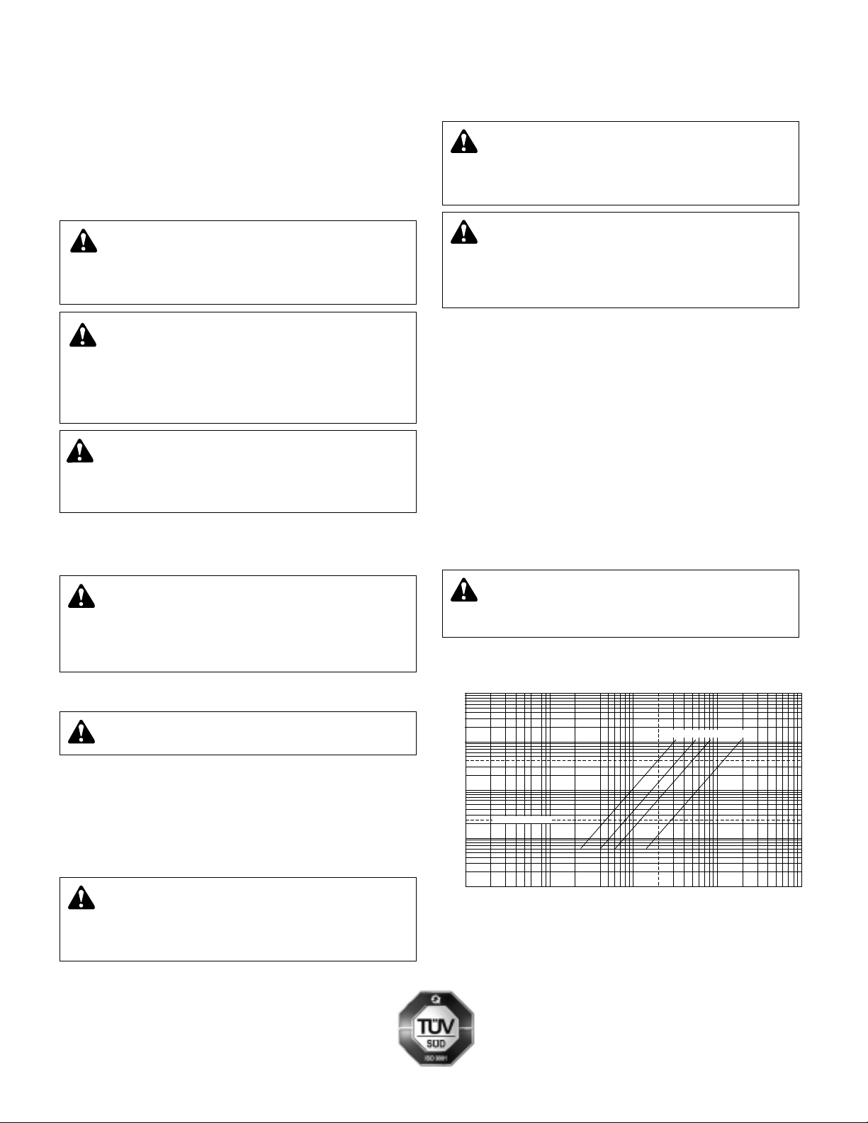
3. Read the differential pressure across the orifice of the 3DV.
4. Use the differential pressure chart (shown below) to read
actual GPM.
Example: The 3DV model 1" NPTF. If the differential pressure across the orifice reads at 40' W.C. the flow rate is
20 GPM.
HOW TO USE THE MEMORY STOP FEATURE
1. Make the final degree of closure setting.
2. Loosen the handle nut and rotate memory stop until it
locks against the body.
3. Tighten the handle nut.
SERVICE INSTRUCTIONS
Periodically inspect the 3DV for signs of leakage or corrosion.
WARNING: Corrosion or leakage is indication that
the 3DV must be replaced. Failure to follow these
instructions could result in serious personal injury or death
and property damage.
PERFORMANCE CHARACTERISTIC CURVE
(NOTE: Flowmeter Cv for Balancing)
1000
CAUTION: Make sure that all the connecting pipework
is water tight.
OPERATION INSTRUCTIONS
1. Energize the zone, circuit and/or system pump(s) as
applicable.
2. Using Bell & Gossett Model RP-250B Readout Probes,
sequentially attach a Bell & Gossett differential pressure
readout kit to the readout valves on each 3DV.
CAUTION: When making the water connections, make
sure that the pipework connecting the 3DV is not
mechanically over-stressed. Over time this could cause
breakages, with consequent water losses which, in turn,
could cause harm to property and/or people.
*Teflon is a registered trademark of E.I. DuPont de Nemours and Company.
Bell & Gossett
8200 N. Austin Avenue
© COPYRIGHT 2006
PRINTED IN U.S.A. 7-06
Morton Grove, IL 60053
Phone: (847) 966-3700
http://www.bellgossett.com
100
40
10
SSERP D ERU ( POR W FO TEEF )RETA
Cv Reference Line
1
0
CAPACITY (GPM)
1" 2"1-1/4" 1-1/2"
0001001020110
 Loading...