

Page 1
Bell & Gossett
Instruction Manual V58583
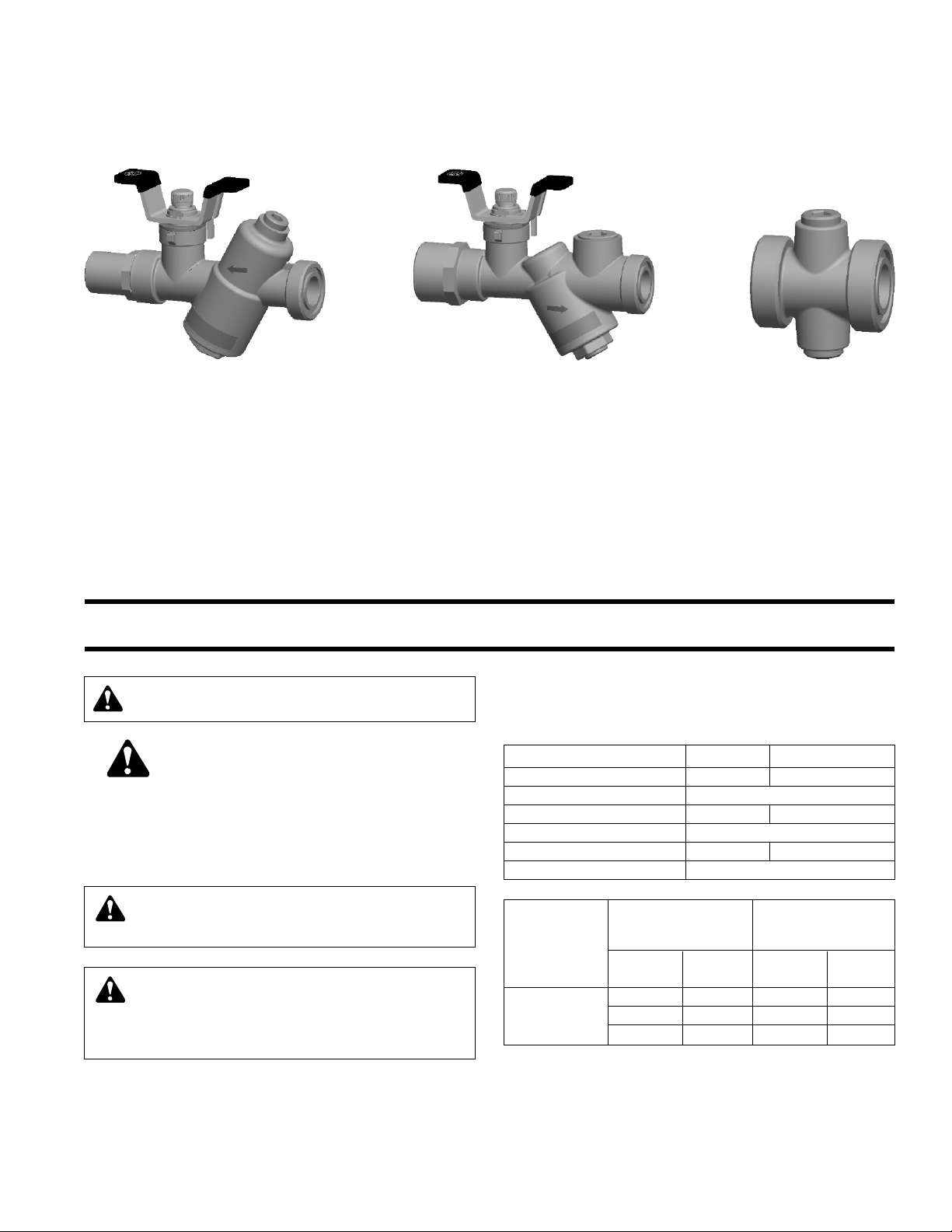
AUTOMATIC FLOW LIMITING VALVE Y-STRAINER VALVE
UNION ACCESSORY
Circuit Sentry
Terminal Kits – Model AC2YL
Installation, Operation and Service Instructions
INSTALLER: PLEASE LEAVE THIS MANUAL FOR THE OWNER’S USE.
NOTE: Bell & Gossett does not recommend Circuit
Sentry Terminal Kits to be used for potable water.
SAFETY
INSTRUCTION
This safety alert symbol will be used in this manual to draw
attention to safety related instructions. When used, the safety
alert symbol means ATTENTION! BECOME ALERT! YOUR
SAFETY IS INVOLVED! FAILURE TO FOLLOW THESE INSTRUCTIONS MAY RESULT IN A SAFETY HAZARD.
OPERATIONAL LIMITS
WORKING PRESSURE & TEMPERATURE LIMITS
(SOLDER TYPE LIMITS FOR ANSI STD. B.16.18)
COIL HOOKUP ACCESSORY TEMP °F (°C) PRESSURE PSI (KPA)
Y-Strainer Valve (NPT) 250 (121) 400 (2758)
Y-Strainer Valve (sweat) Based on solder type ASTM Std. B16.18
Union Ended Ball Valve (NPT) 250(121) 400 (2758)
Union Ended Ball Valve (sweat) Based on solder type ASTM Std. B16.18
Union Accessory (NPT) 250 (121) 400 (2758)
Accessory (sweat) Based on solder type ASTM Std. B16.18
WARNING: This product contains a chemical known
by the State of California to cause cancer and birth
defects or other reproductive harm.
WARNING: It is possible, depending on the age or
condition of the drain valve stem seal, for some liquid
to escape when closing the valve. Do not have eyes or
face directly above valve. Failure to follow these instructions could result in serious personal injury.
MAXIMUM MAXIMUM
TYPE OF 1/2" – 1" 11/4" – 2"
SOLDER
95-5
TIN- 250 (1724) 225 (107) 250 (1724) 200 (93)
ANTIMONY
LIMITATIONS LIMITATIONS
PRESSURE TEMP PRESSURE TEMP
PSI (kPa) °F (°C) PSI (kPa) °F (°C)
300 (2069) 200 (93) 300 (2069) 175 (79)
200 (1379) 250 (121) 175 (1207) 250 (121)
Page 2
HOW TO USE PRESSURE TAPS
TO MEASURE SYSTEM
OPERATING CONDITIONS
1. Using Bell & Gossett Model RP-250B, readout probes,
attach Bell & Gossett differential pressure readout kit to the
readout valves on the Accessory valve.
2. Read the differential pressure from the coil inlet isolation
valve (typically strainer) to coil outlet isolation valve (typically flow limiting balancing valve). Differential value should
be between the sum of the coil, and control valve pressure
drop and 60 psi depending upon the amount of control
being exercised by the flow limiting valve function for balance. Optional pressure reading valves (B&G P/N V58050)
may be installed in the barrel of the strainer, flow limiting
valve or union connection for the coil for a more discrete
reading if desired. Valves should be installed with coil and
barrels isolated and drained.
GENERAL INFORMATION
For installing Sweat Connections:
a) Clean tube ends and valve connections thoroughly per
good piping practices with a fine grade emery cloth or fine
grit sandpaper.
b) For soldering, use 95-5 (Tin-Antimony) solder and a good
grade of flux.
c) Use a torch with a sharp pointed flame.
d) When sweating the joints, first adjusting the valve in the full
open position, then wrap the valve with a cool wet rag and
then direct the flame with care to avoid subjecting the
valve to excessive heat. Allow the valve to cool before
touching or operating.
e) Check the soldered connection for leaks.
For installing NPT connections:
Apply pipe compound conservatively to male connecting fittings only. After installation check all joints for leakage and retighten where necessary.
AUTOMATIC FLOW LIMITING VALVE
DESCRIPTION
Low Flow AC valve is designed to automatically control the
flow in piping systems to selected preset limit. As pressure
differential increases, a cartridge inside the valve body
reduces the flow area to accurately maintain the preselected
flow rate.
Flow Operating Range: 0.25 – 3.8 GPM
INSTALLATION INSTRUCTIONS
1. The Automatic Flow Limiting Valve must be installed on the
return side of the coil with union end on the upstream side
and fixed end on the downstream side of the flow.
2. Install the unit so that the flow arrow on the body housing
points in the direction of flow.
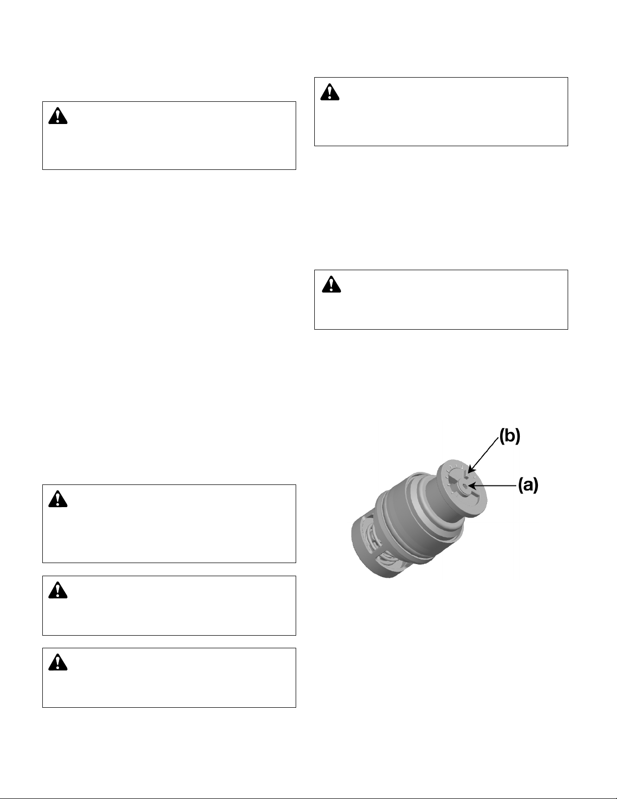
3. Prior to coil commissioning and operating the Flow
Limiting Valve, adjust cartridge to the desired flow rate
between 0.25 GPM to 3.8 GPM.
i. Loosen screw (a) position
ii. Rotate plastic pointer (b) to the desired flow rate.
Increments marked on variable orifice are in GPM.
iii. Re-tighten screw (a) with pointer set at the desired flow
rate.
CAUTION: The use of Teflon®* impregnated pipe
compound and Teflon tape on pipe threads provides
lubricity. Care should be taken to prevent overtightening
which may damage the valve body. Failure to follow these
instructions can result in moderate personal injury and/or
property damage.
WARNING: Use of improper procedures to sweat
valve model with union connection into system can
damage valve. Before installing sweat union connection to
valve, remove the union nut and O-ring from the valve
body, then union tailpiece with union nut must be sweated
(soldered) into place. Failure to follow this instruction could
result in property damage and/or moderate personal injury.
CAUTION: Excessive use of solder or flux may result
in damage to the shutoff valve seat and ball. Do not
use excessive solder or flux. Failure to follow these
instructions can result in moderate personal injury and/or
property damage.
CAUTION: Heat associated with the use of silver
solder may damage valve components and void the
product warranty. Do not use silver solder. Failure to follow these instructions could result in property damage
and/or moderate personal injury.
*Teflon is a registered trademark of E.I. DuPont de Nemours and Company.
WARNING: Damage to the Low Flow AC valve or
failure of solder sealing joints may occur if these operational limits are exceeded. This can result in water leakage. Failure to follow this instruction can cause serious
personal injury and/or property damage.
WARNING: Hot water leakage can occur from read-
out valves during probe insertion and during hookup
of readout kit. Follow the instruction manuals supplied with
readout probes and readout kits for safe use. Failure to
follow these instructions could result in serious personal
injury or death and property damage.
2
Page 3

4. Install the cartridge as shown below.
OPERATION INSTRUCTIONS
Operation of the Flow Limiting Valve is fully automatic. It automatically maintains the selected flow over the designed differential pressure range.
Before the system start up, remove cartridge from valve if
previously installed. Flush the hydronic system and then reassemble cartridge into the valve and mark sure cap is tightened properly. Start the system and check for the Low Flow
AC valve leak.
SERVICE INSTRUCTIONS
Should the Flow Limiting Valve require cleaning or changing
the flow rate, follow the following instructions.
1. Loosen and remove the cap from the valve body.
2. Pull the cartridge assembly from the valve body for cleaning or replacing with the new flow cartridge. Check the cartridge by pushing the orifice washer into the cartridge
housing for several times to make sure spring is functional.
Y-STRAINER COMBINATION VALVE
DESCRIPTION
Low Flow Y-strainer Valves are made of brass construction
with an integrated ball valve and strainer.
INSTALLATION INSTRUCTIONS
1. The valves must be installed on the supply side of the coil
with fixed end on the upstream side and union end on the
downstream side.
2. When installing the Y-strainer valves, space around the
units must be provided to remove the strainer from the
strainer body for cleaning.
3. The Y-Strainer must be installed with the strainer chamber
down to prevent air binding and also to allow accumulated
dirt for ease of cleaning.
OPERATING INSTRUCTIONS
Y-strainer can be used to isolate hydronic equipment for
repairs and/or to drain the system. To close the Y-strainer ball
valve, move the handle a quarter of a turn until the handle is
perpendicular to the valve and piping.
If Y-strainer pressure drop becomes excessive accumulated
dirt should blown through the blow-down line (if installed) to a
drain. If a blow-down line is not installed, see the service
instructions for removing and cleaning the strainer. The
Y-strainers have construction with an integrated ball valve will
function as a service valve.
SERVICE INSTRUCTIONS
If excessive pressure drop is noted across the Y-Strainer the
internal strainer has collected a lot of dirt/debris and needs to
be cleaned. Install blow-down line (hose), then open blowdown valve. If a blowing down the strainer has not solved the
pressure drop problem, the Y-strainer must be disassembled
and strainer to be cleaned.
To clean the strainer, isolate the Y-Strainer from the ball valve
on upstream and downstream of the strainer. Allow the system to cool to 100°F (38°C) or less.
Using the appropriate size wrench remove the brass cap
on the Y-strainer. Grab and remove the strainer. Clean the
strainer in water to remove collected debris. Reinstall the
strainer and the strainer cap. Pressurize the system and
check for strainer cap leaks. If noted, slightly tighten nut until
leakage stops.
Periodically inspect the Y-Strainer for signs of corrosion or
leakage. If corrosion or leakage is noted the Y-Strainer must
be replaced.
WARNING: Corrosion or leakage are indications that
the Flow Limiting Valve may be about to cause serious damage. The Flow Limiting Valve must be replaced.
Failure to follow these instructions could result in serious
personal injury or death and property damage.
CAUTION: Make sure Valve Cap is properly assembled.
Failure to follow these instructions can result in moderate personal injury and/or property damage.
3
CAUTION: Hot un-insulated surfaces can cause
burns to the skin. Do not touch hot surfaces. Failure
to follow these instructions could result in moderate personal injury.
CAUTION: Hot un-insulated surfaces can cause
burns to the skin. Do not touch hot surfaces. Failure
to follow these instructions could result in moderate personal injury.
WARNING: Hot fluids and/or fluids under pressure
are a safety hazard. Do not service the strainer while it
is hot or under pressure. Failure to follow these instructions could result in serious personal injury or death and
property damage.
WARNING: Corrosion or leakage are indications that
the Y-Strainer Valve must be replaced. Failure to follow these instructions could result in serious personal
injury or death and property damage.
Page 4

LOW FLOW UNION ACCESSORY
DESCRIPTION
Union Accessory is of brass construction with includes two (2)
1-1/4" threads of the union connections and two (2) plugs
INSTALLATION INSTRUCTIONS
The Union Accessory must be installed on the return side of
the coil.
When an air vent is included, make sure the vent is facing
upward.
OPERATION INSTRUCTIONS
Union Accessory is used for installation of accessories.
CAUTION: Hot un-insulated surfaces can cause
burns to the skin. Do not touch hot surfaces. Failure
to follow these instructions could result in moderate personal injury.
SERVICE INSTRUCTIONS
Periodically inspect the Union Accessory for signs of leakage
or corrosion.
WARNING: Corrosion or leakages is indication that
the Union Accessory Valve must be replaced. Failure
to follow these instructions could result in serious personal injury or death and property damage.
© COPYRIGHT 2006 BY
PRINTED IN CHINA 10-06
8200 N. Austin Avenue
Morton Grove, IL 60053
Phone: (847) 966-3700
Fax: (847) 966-9052
http://www.bellgossett.com
 Loading...