

Page 1
INSTRUCTION MANUAL
V58046B
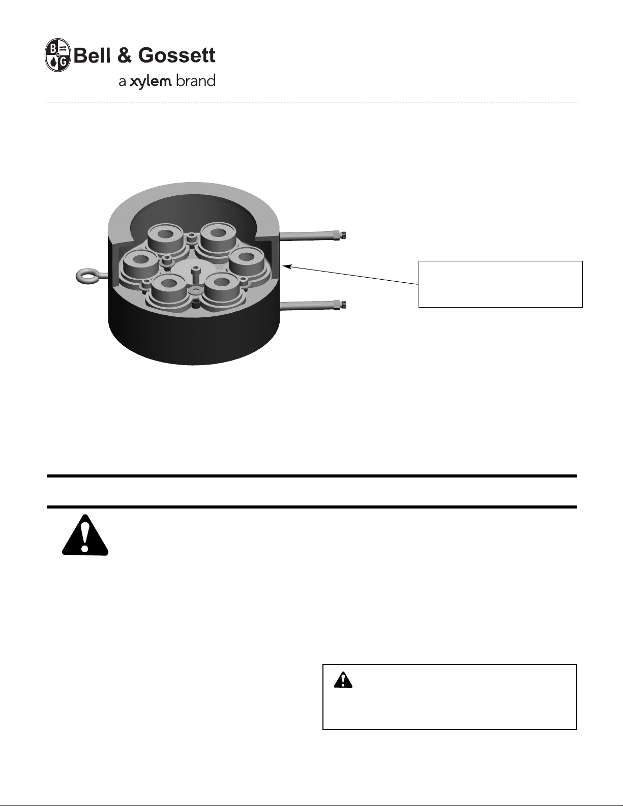
WA RN IN G LABEL P AR T NO. V5 6871
INSTALLED IN THIS LOCATION (UNDER
BELL & GOSSETT). IF MISSING IT MUST
BE REPLACED.
Wafer Valve
Automatic Flow-Limiting Valve
INSTALLER: PLEASE LEAVE THIS MANUAL FOR THE OWNER’S USE.
INSTALLATION INSTRUCTIONS
SAFETY
INSTRUCTION
This safety alert symbol will be used in this manual to draw
attention to safety related instructions. When used, the safety
alert symbol means ATTENTION! BECOME ALERT! YOUR
SAFETY IS INVOLVED! FAILURE TO FOLLOW THESE INSTRUCTIONS MAY RESULT IN A SAFETY HAZARD.
DESCRIPTION
The Bell & Gossett WAFER Valve is designed to fit between
two 150 lb. ASME flanges and to automatically control the
flow in a piping system to a selected preset flow requirement.
As pressure differential increases, a cartridge inside the valve
body reduces the flow area to accurately maintain the preselected flow rate.
Operational Limits
Maximum Operating Temperature: 250ºF (121ºC)
Maximum Op
Flow Control, Differential Pressure:
2 to 60 psig (14 to 414 kPa) nominal
erating Pressure: 250 psig (1724 kPa)
1. For installing Wafer Valves:
a) Install the Wafer valve in the piping system/circuit
where it is desired to maintain the flow at a preselected value. The lifting lug (eye-bolt) provided (from
4" thru 20") will make handling of the valve easier.
In stall the lifting lu
between two identical 150 lb. ASME flanges. Use long
threaded rods to connect the two flanges together
and secure the wafer valve and mating gasket in full
contact with the flanges. Torque each nut on the
threaded rod to specified torque value necessary for
typical flange torque connections.
CAUTION: Use unit lifting eyes only to lift unit as
shipped from factory. Unit must be empty and
disconnected from pipe, and other restraints. Use proper
rigging procedures. Failure to follow these instructions
could result in injury or property damage.
b) Install the unit so that the flow arrow on the body
housing points in the directio
g i nt o t he valve body. Install
n of flow.
Page 2
c) Install the pressure readout fittings into the valve
body using the extension adapters first. Then install
the pressure and temperature access port onto the
extension adapter
1
/4 inch NPT end.
SERVICE INSTRUCTIONS
Should the Wafer Valve require cleaning or changing the
orifice, consult the following instructions.
CAU TI O N: The gen erous us e of pi pe jo int
compound when installing the adapter or P/T will
foul the valve operating mechanism preventing it from
functio ning properly. Pipe joint compound must be
conservatively applied to male threads only. Failure to
follow this instruction can result in moderate personal
injury and/or property damage.
CAUTION: The use of PTFE impregnated pipe
compound and PTFE tape on pipe threads
provides lubricity, which can lead to overtightening and
breakage. Do n ot overtighten. Failure t o follow this
instruction can result in moderate personal injury and/or
property damage.
OPERATING INSTRUCTIONS
Operation of the Wafer Valve is fully automatic and does not
re qu ir e a ny ad ju stment. It a utomatically maintains the
selected flow over the designed differential pressure range.
CAUTION: Hot uninsulated surfaces can cause
burns to the skin. Do not touch hot sur faces.
Fa il ure to foll ow these instruct io ns could result in
moderate personal injury.
HOW TO USE AUTOMATIC FLOW-LIMITING
VALVE PRESSURE TAPS TO DETERMINE
PROPER FUNCTIONING OF VALVE.
1. Using Bell & Gossett Model RP-250 readout probes,
attach a Bell & Gossett differential pressure readout kit to
the readout valves on the Automatic Flow-Limiting Valve.
WAR NING: Hot water leakage can occur from
readout valve during probe insertion and during
hookup of readout kit. Follow the instruction manual
supplied with readout probes and readout kits for safe
use. Failure to follow this instruction could result in
serious personal injury and/or property damage.
WARNING: System fluid under pressure and/or at
high temperature can be very hazardous. Before
servicing, reduce system pressure to zero or isolate the
pressure reducing from the system. Leave drain valve
open. Allow system to cool below 100ºF. Failure to follow
these instructions could result in serious personal injury
or death and property damage.
1. Re move the valve body from the piping syste m b y
unbolting it from the two flanges on either side. Use the
lifting lug (eye-bolt for 4" thru 20") to handle/carry the
valve.
2. Pull the cartridge assembly from the valve body for
cleaning or change to new flow cartridge. The cartridge is
secured
to the mid-plate of the housing by means of 2 or
3 allen head screws. Remove the screws first. Then pull
the cartridge out of the mid-plate bore. Checking the
cartridge by pushing the orifice washer in to the cartridge
housing against the spring force for several times to
make sure spring is functional. Inspect the interior of
cartridge for broken spring or any particles stuck inside
that may prevent fr
ee movement of the cartridge housing.
3. To change the orifice washer (for different flow rate),
remove the clip ring from inside the cartridge housing
with a screwdriver. Pull the orifice wa sher out and
replace it with the new orifice (orifice part number should
be facing upward). Push the new orifice in until it seats all
the way to the bottom of the shelf.
4. Reinstall, or replace the clip ring in the c
artridge-housing
groove and make sure that it is holding the new orifice
disk securely in place.
5. Reassemble the cartridge into the mid-plate bore and
secure with the allen head screws.
WARNING: Corrosion or leakages are indications
th at the Wafer Valve ma y b e about to cause
serious damage from leakage or rupture. It must be
periodically inspected and if noted, it must be replaced.
Failure to follow these instructions could result in serious
personal injury or death and property damage.
2. Read the differential pressure across Wafer Valve. This
can be compared to system pump head to determine
valve function, and system flow blockage.
Xylem Inc.
8200 N. Austin Avenue
Morton Grove, Illinois 60053
Phone: (847) 966-3700
Fax: (847) 965-8379
www.xyleminc.com/brands/bellgossett
Bell & Gossett is a trademark of Xylem Inc. or one of its subsidiaries.
© 2012 Xylem Inc. V58046B September 2012
 Loading...