

Page 1
INSTRUCTION MANUAL
WARNING: Label Part No. V56873
installed in this location (under
Bell & Gossett). If missing it must
be replaced.
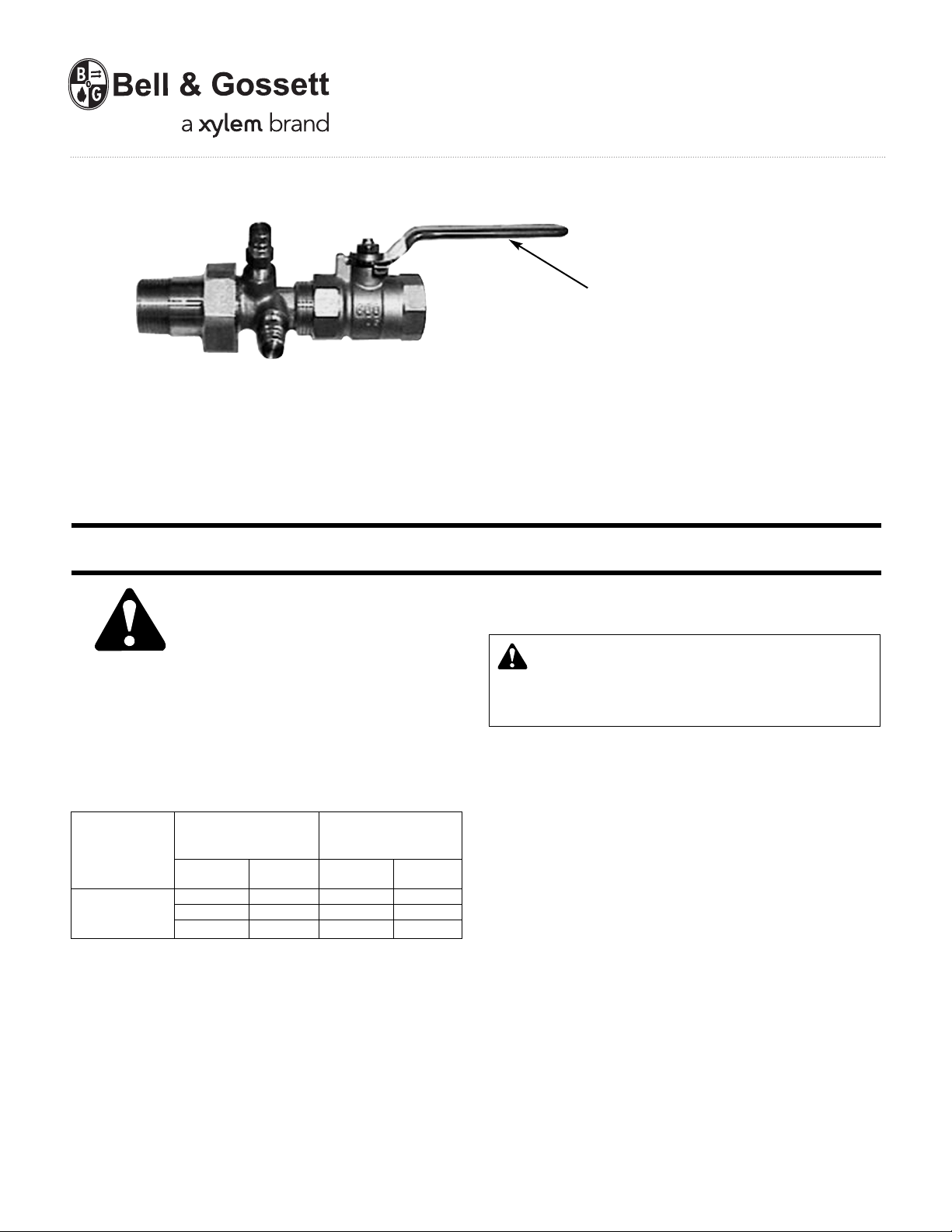
Venturi/Ball Valve Combination
V57895B
Model MV
INSTALLER: PLEASE LEAVE THIS MANUAL FOR THE OWNER’S USE.
SAFETY
INSTRUCTION
This safety alert symbol will be used in this manual to draw
attention to safety related instructions. When used, the safety
alert symbol means ATTENTION! BECOME ALERT! YOUR
SAFETY IS INVOLVED! FAILURE TO FOLLOW THESE INSTRUCTIONS MAY RESULT IN A SAFETY HAZARD.
OPERATIONAL LIMITS
WORKING PRESSURE & TEMPERATURE LIMTS
(SOLDER TYPE LIMITS FOR ANSI STD. B.16.18)
MAXIMUM MAXIMUM
TYPE OF 1/2" – 1" 11/4" – 2"
SOLDER PRESSURE TEMP PRESSURE TEMP
95-5 300 (2069) 200 (93) 300 (2069) 175 (79)
TIN- 250 (1724) 225 (107) 250 (1724) 200 (93)
ANTIMONY 200 (1379) 250 (121) 175 (1207) 250 (121)
NPT
Maximum Operating Pressure 400 psig (2758 kPa)
Maximum Operating Temperature 250°F (121°C)
LIMITATIONS LIMITATIONS
PSI (kPa) °F (°C) PSI (kPa) °F (°C)
Venturi/Ball valve provides highly accurate flow measurement
capabilities.
WARNING: Damage to the Venturi/Ball valve or failure
of solder sealing joints may occur it these operational
limits are exceeded. This can result in water leakage.
Failure to follow this instruction can cause serious personal injury and/or property damage.
INSTALLATION INSTRUCTIONS
1. For installing Sweat Connections:
a) Clean tube ends and valve connections thoroughly per
good piping practices with a fine grade emery clot
fine grit sandpaper.
b) For soldering, use 95-5 (Tin-Antimony) solder and a
good grade of flux.
c) Use a torch with a sharp pointed flame.
d) When sweating the joints, first adjusting the valve in the
full open position, then wrap the valve with a cool wet
rag and then direct the flame with care to avoid subjecting the valve to excessive heat. Allow the valve to cool
before touching or operating.
e) Chec
k the soldered connection for leaks.
h or
DESCRIPTION
The Bell & Gossett Model MV is a combination calibrated balance, commissioning and positive shutoff valve for use in
HVAC systems. An efficient brass venturi design provides
accurate flow balancing with minimal system pressure loss.
Valves are furnished with two readout valves (pressure and
temperature p
stop, and a hanging ID tag for commissioning. A variety of
end connections are available on both the fixed and union
ends.
orts), standard port ball valve with memory
Page 2
WARNING: Use of improper procedures to sweat
valve model with union connection into system can
damage valve. Before installing sweat union connection to
valve, remove the union nut and O-ring from the valve
body, then union tailpiece with union nut must be sweated
(soldered) into place. Failure to follow this instruction could
result in property damage and/or moderate personal injury.
CAUTION: Heat Associated with the use of silver
solder may damage a Venturi/Ball valve and void the
product warranty. Do not use silver solder. Failure to follow
these instructions could result in property damage and/or
moderate personal injury
2. For installing NPT connections:
Apply pipe compound conservatively to male connecting
fittings only.
CAUTION: The use of PTFE impregnated pipe
compound and PTFE tape on pipe threads provides
lubricity. Care should be taken to prevent overtightening
which may damage the valve body. Failure to follow these
instructions can result in moderate personal injury and/or
property damage.
After installation check all joints for leakage and retighten
where necessary.
OPERATION INSTRUCTIONS
1. Energiz e the zone, c ircuit a nd/or sy stem pump(s) as
applicable.
2. Using Bell & Gossett Model RP-250B Readout Probes,
sequentially attach a Bell & Gossett differential pressure
readout kit to the readout valves on each Venturi/Ball
valve.
WARNING: Hot water leakage can occur from readout valves during probe insertion and during hookup
of readout kit. Follow the instruction manuals supplied with
readout probes and readout kits for safe use. Failure to
follow these instructions could result in serious personal
injury or death and property damage.
3. Read the differential pressure across the orifice of the
Venturi/Ball valve.
4. Using the differential pressure data sheet #EP-600 of the
Venturi/Ball valve to read actual GPM.
Example: The Venturi/Ball valve model 3/4" L. If the differential pressure across the orifice read at 46" W.C. the
flow rate is 4 GPM.
HOW TO USE THE MEMORY STOP FEATURE
1. Make the final degree
of closure setting.
2. Loos en the handle nut and rot ate memory st op un til
against the body locking.
3. Tighten the handle nut.
SERVICE INSTRUCTIONS
Periodically inspect the Venturi/Ball for signs of leakage or
corrosion.
WARNING: Corrosion or leakage is indication, that
the Venturi/Ball must be replaced. Failure to follow
these instructions could result in serious personal injury or
death and property damage.
Xylem Inc.
8200 N. Austin Avenue
Morton Grove, Illinois 60053
Phone: (847) 966-3700
Fax: (847) 965-8379
www.xyleminc.com/brands/bellgossett
Bell & Gossett is a trademark of Xylem Inc. or one of its subsidiaries.
© 2012 Xylem Inc. V57895B September 2012
 Loading...