

Page 1
INSTRUCTION MANUAL
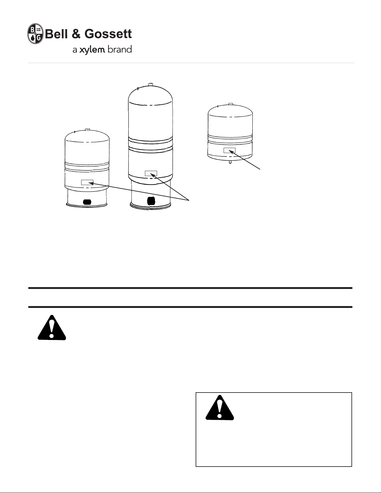
WARNING: Label Part No. 9017-078
must be installed in this location.
If missing, it must be replaced.
WARNING: Label Part No. 9015-463
must be installed in this location.
If missing, it must be replaced.
V57083D
Diaphragm Expansion Tanks
ASME And Non-Code
INSTALLER: PLEASE LEAVE THIS MANUAL FOR THE OWNER’S USE.
water systems. The well tank delivers adequate water under
SAFETY
INSTRUCTION
This safety alert symbol will be used in this manual to draw
attention to safety related instructions. When used, the safety
alert symbol means ATTENTION! BECOME ALERT! YOUR
SAFETY IS INVOLVED! FAILURE TO FOLLOW THESE INSTRUCTIONS MAY RESULT IN A SAFETY HAZARD.
DESCRIPTION
Series “PT” and “PTA” expansion tanks are precharged
diaphragm-type vessels. The PTA Series meet the requirements of the ASME boiler and pressure vessels code. The
Series “PT” and “PTA” tanks are designed to absorb the force
of expanding water and protect the potable water system
from pressure build up. Refer to table 1 on page 2 for pressure and temperature information.
Series “WTX”, “WT” and “WTA” tanks are precharged
diaphragm-type vessels. The WTA Series meet the requirements of the ASME boiler and pressure vessels code. The
Series “WTX”, “WT” and “WTA” tanks help protect the pump
and pressure switches against short cycling in potable well
pressure between pump cycles to meet the required demand.
It will provide economical system operation by minimizing
pump starts and saving energy. Refer to table 1 on page 2 for
pressure and temperature information.
The Series “HFT” tank is designed to absorb the expansion
force in heating water and maintain proper pressurization in a
closed hydronic system. The Series “HFT” tank is not for use
in potable water systems. Refer to table 1 on page 2 for pressure and temperature information.
SERIES HFT TANKS ARE
NOT FOR USE IN POTABLE
WATER SYSTEMS
WARNING: Potable or fresh water can cause serious
corrosion in Series HFT tanks. This can result in leakage
and a potential explosion. Do not use HFT tanks for
potable or fresh water applications. Failure to follow this
instruction will result in serious personal injury or death
and property damage.
Page 2
INSTALLATION INSTRUCTIONS
A. Pre-Installation
1. Inspect the expansion tank for damage.
WARNING: If the expansion tank is damaged, it
must be exchanged for a new tank. The tank could
rupture. Failure to follow these instructions could result in
serious personal injury or death and property damage.
2. For a residential potable water installation where:
a. cold water supply (CWS) pressure is less than 80 psig
and the water heater size is up to 120 gallons with an ending temperature setting of up to 160°F, the air charge of
the PT-12 Model does not need to be changed.
b. cold water supply pressure (CWS) is greater than 80
psig, the air charge of the PT-12 Model must change to
equal the incoming pressure by charging the expansion
tank with oil free compressed air. Check the pressure frequently during this process when filling with air to avoid
over pressurizing the tank.
WARNING: Excessive pressure can cause tank to
explode. Exercise care when filling a tank with air so
the pressure does not exceed that required or does not
exceed the working pressure of the tank as stamped on
the nameplate. Failure to follow these instructions will
result in serious personal injury or death and property
damage.
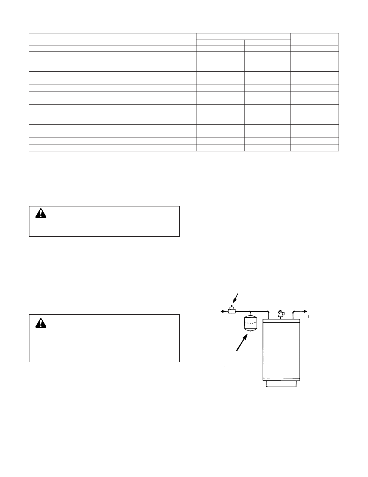
B. Installation (“PT” & “PTA” Series)
1. Install the expansion tanks on the cold water supply (CWS)
line at a point between the water heater and backflow preventer, check valve or pressure reducing valve (see Figure 1).
2. Once tank is installed, fill system and check for any leakage. Make repairs if necessary.
3. Before the initial firing of the water heater, open a hot water
fixture and draw water until all air is removed from the system. Turn the water heater temperature control
to desired ending temperature level (see water heater
instructions).
4. To relieve initial thermal expansion, slightly open a hot
water faucet. Continue until water heater aquastat temperature is satisfied. Once heater is at its operating range, no
further bleeding of expanded water is required.
5. The system water heater and expansion tank will now be
operational. The expansion tank will absorb pressure
increases caused by thermal expansion to a level well
below the water heater relief valve setting.
2
MAXIMUM LIMITATIONS FACTORY
MODEL NUMBER PRESSURE TEMPERATURE PRE-CHARGE
All HFT 100 PSIG (689 kPa) 240°F (115°C) 12 PSIG (83 kPa)
PT-5, PT-12, PT-25V, PT-30V, PT-42V, PT-60V,
PT-80V, PT-180V, PT-210V
150 PSIG (1035 kPa) 200°F (93°C) 40 PSIG (276 kPa)
PT-451 through PT-457 150 PSIG (1035 kPa) 240°F (115°C) 55 PSIG (379 kPa)
PTA-5, PTA-12, PTA-20V, PTA-30V, PTA-42V, PTA-60V,
PTA-80V, PTA-180V, PTA-210V
150 PSIG (1035 kPa) 200°F (93°C) 55 PSIG (379 kPa)
PTA-451 through PTA-457 125 PSIG (862 kPa) 240°F (115°C) 55 PSIG (379 kPa)
WTX-2, WTX-5 100 PSIG (689 kPa) 200°F (93°C) 18 PSIG (124 kPa)
WTX-8 100 PSIG (689 kPa) 200°F (93°C) 28 PSIG (193 kPa)
WTX-10, WTX-14, WTX-10S, WTX-14S, WTX-20S, WTX-26S, WTX-32S,
WTX-34S, WTX-44S, WTX-62S, WTX-81S, WTX-86S, WTX-119S
100 PSIG (689 kPa) 200°F (93°C) 38 PSIG (262 kPa)
WTA-401 through WTA-405 125 PSIG (862 kPa) 200°F (93°C) 30 PSIG (207 kPa)
WTA-447 through WTA-457 125 PSIG (862 kPa) 240°F (115°C) 25 PSIG (172 kPa)
TABLE 1
BACK FLOW PREVENTER
CHECK VALVE
RELIEF VALVE
HOT
WATER
CWS
WATER
HEATER
PT OR PTA
TANK
TYPICAL INSTALLATION
FIGURE 1
WT-401 through WT-405 150 PSIG (1035 kPa) 200°F (93°C) 30 PSIG (207 kPa)
WT-421 through WT-427 100 PSIG (689 kPa) 240°F (115°C) 25 PSIG (172 kPa)
WT-447 through WT-457 150 PSIG (1035 kPa) 240°F (115°C) 25 PSIG (172 kPa)
Page 3

C. Installation ( “HFT” Series)
The series “HFT” may be installed into a tee or any other suitable tapping on a water heating system, preferably on the
suction side of the circulator. (see Figure 2).
SYSTEM VENTING AND PURGING
(For hydronic heating systems not
potable water systems)
After initial venting and purging of air from the system, more
air will be released from the water as it is heated. Therefore, it
is recommended that a B&G air separator be installed on the
main.
If the system has multiple loops or zones, the supply water for
all loops and zones must pass through the air separator for
complete and continuous air removal. In case the piping
arrangement does not permit the installation of a single air
separator on the main, air separators should be installed on
each loop or zone. In this event, only one expansion tank is
required for the system.
Even with a B&G air separator installed on the main or mains,
it is recommended that B&G air vents be installed on high
points in the system.
It is also recommended that manual (key or coin type) air
vents be installed at higher points on the radiation.
D. Installation ( “WTX”, “WT” & “WTA” Series)
The well tank should be installed as close as possible to the
pressure switch. Inline models are generally installed directly
into the main water supply with a
3
/4" connection. The floor
models are generally installed using a tee off main. (See figures 3 & 4.) The air pressure should be adjusted to 1-2 PSIG
below the pressure switch pump “cut-in” setting. (Tank should
be at room temperature and empty of water when adjusting
the air pressure.) Refer to Table 1 for the factory pre-charge
pressure.
System Connection
1. Locate desired tank location.
2. Level the tank as necessary.
3. Connect to pump supply line with the same size pipe as
from pump.
4. All piping should be in accordance with local code require-
ments
OPERATING INSTRUCTIONS
1. The expansion tank’s sealed-in-air pre-charge prevents
water from entering the tank until the system pressure
exceeds the pre-charge pressure.
2. As the water temperature rises, expanded water enters the
expansion tanks water reservoir. The pre-charged air
chamber absorbs the pressure increase, keeping system
pressures below the relief valve setting.
3. As water is used in a potable well system, the pressure in
the air chamber forces water back into the system until the
pressure switch pump “cut-in” setting is reached. The
pump will then turn on forcing water into the tank until the
pump “cut-out” pressure is reached. The water stored in
the tank is supplied to the potable water system under
pressure without the pump turning on.
3
TYPICAL INSTALLATION
FIGURE 2
B&G PRESSURE
REDUCING VALVE
CW FILL
SHUT-OFF
VALVE
B&G RELIEF
VALVE
DIAPHRAGM TYPE
EXPANSION TANK
“HFT”
B&G BOOSTER
FLO-CONTROLB&G
VALVE
TO
SYSTEM
BOILER
RETURN
OPTIONAL SIDE
OUTLET BOILER
CONNECTION
AIR SEPARATOR
FLOW
INSTALLATION WITH JET PUMP
FIGURE 3
INSTALLATION WITH SUBMERSIBLE PUMP
FIGURE 4
INLINE
WELL
TANK
PRESSURE
SWITCH
FLOOR
MOUNT
WELL
TANK
TO SYSTEM
PRESSURE
SWITCH
FROM WELL
PRESSURE
SWITCH
TO WELL
TANK
PRESSURE
GAUGE
RELIEF VALVE
TO SYSTEM
DRAIN
RELIEF
VALVE
SUBMERSIBLE
PUMP
DRAIN
Page 4

AIR
CUSHION
AIR
CUSHION
AIR
CUSHION
AIR
CUSHION
AIR
CUSHION
AIR
CUSHION
MODELS
PT-5 & PT-12
PTA-5 & PTA-12
HFT-15 THRU HFT-90
WTX-2 THRU WTX-14
HFT-30V THRU HFT-160V
WTX-10S THRU WTX-119S
MODELS
PT-25V & PT-457
PTA-20V & PTA-457
ALL WT & WTA MODELS
SERVICE INSTRUCTIONS
1. Check the expansion tank periodically for signs of external
leakage or corrosion. If found, the tank must be replaced.
WARNING: Signs of leakage or corrosion are
indications the tank may fail. Periodically check the
expansion tank for signs of external leakage or corrosion.
If found, the tank must be replaced. Failure to follow these
instructions will result in serious personal injury or death
and property damage.
2. If a HVAC system is shut down for long periods or emptied
for any reason, it is necessary to follow the following procedure:
a) Fill system.
b) Vent air from system (see system venting and purging).
c) Bring system up to maximum operating temperature.
3. If the system pressure is too high:
a. Check gauge calibration.
b. Check to see if expansion tank has lost its air charge.
Note: To check the expansion tank air pressure with a
tire gauge either:
1. Disconnect the expansion tank from the system or,
2. Draw off system water until boiler pressure reads
zero or isolate the expansion tank from the system
in domestic water systems, and bleed pressure
from the system. All drains must be kept open during
servicing of expansion tank. (Expansion tank must be
empty of expanded system water.)
3. Then check tank pressure with tire air gauge.
WARNING: Improper use of air charging valve
during venting of air pressure from tank will create a
hazardous condition due to the escape of high velocity
gas and/or liquid. Depress the center valve core stem,
as with a tire valve to slowly vent off gas pressure. Do
not remove the valve core until pressure in the expansion
tank has reached zero. Failure to follow these instructions
could result in serious personal injury or death and
property damage.
c. Check for faulty fill valve operation. First, close manual
shut-off located before the fill-valve; then, draw system
pressure down to pre-set pressure (see TABLE 1) open
shut-off valve and observe system for pressure build-up
several hours later. If pressure build up beyond set pressure is found, replace fill valve following manufacturers
instruction.
d. Check for service water entering system from any other
source such as a defective tankless heater or indirect
fired water storage tank. Use same procedure as above
after shutting off possible water source. Replace defective device if found following manufacturers instruction.
4. If pressure relief valve drips water:
a. First, check system pressure. If too high, follow steps 3.
a., b., c. and d. above.
b. If pressure relief valve continues to drip water, even at
reduced pressure, flush relief valve by quickly raising
lever several times. If drip continues, replace relief valve
following manufacturers instruction.
c. If multiple expansion tanks are installed in the system,
check pressure of each for possible air leaks. Be sure
plastic air valve caps are on tight. Multiple tanks should
be in the same location.
Xylem Inc.
8200 N. Austin Avenue
Morton Grove, Illinois 60053
Phone: (847) 966-3700
Fax: (847) 965-8379
www.xyleminc.com/brands/bellgossett
Bell & Gossett is a trademark of Xylem Inc. or one of its subsidiaries.
© 2012 Xylem Inc. V57083D May 2012
 Loading...