

Page 1
INSTRUCTION MANUAL
SRS
Pneumatic
Purge Valve
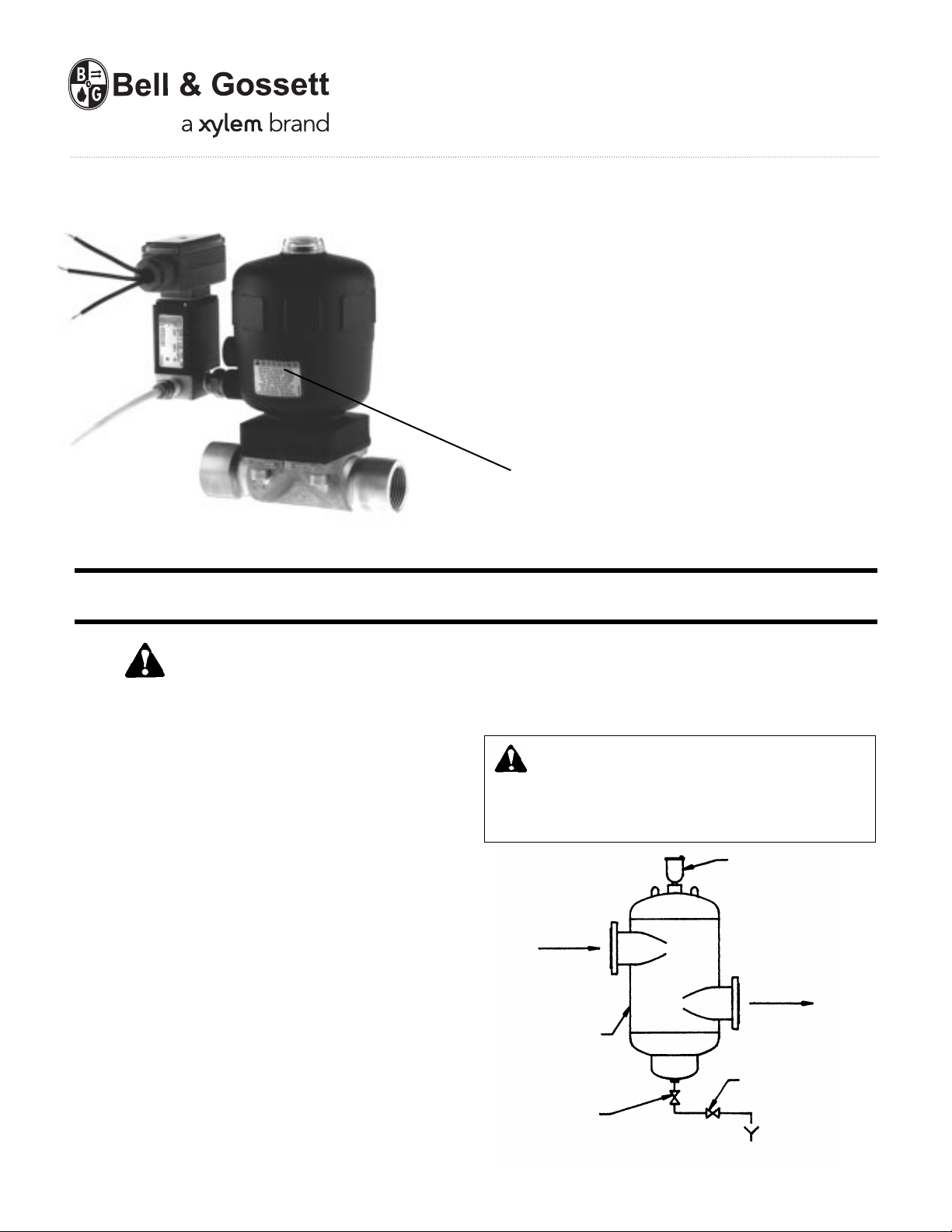
WARNING LABEL PART NO. V56845
INSTALLED IN THIS LOCATION.
IF MISSING, IT MUST BE REPLACED.
V57050B
INSTALLER: PLEASE LEAVE THIS MANUAL FOR THE OWNER’S USE.
SAFETY
INSTRUCTIONS
This safety alert symbol will be used in this manual to draw
attention to safety related instructions. When used, the safety
alert symbol means ATTENTION! BECOME ALERT! YOUR
SAFETY IS INVOLVED! FAILURE TO FOLLOW THESE INSTRUCTIONS MAY RESULT IN A SAFETY HAZARD.
DESCRIPTION
The SRS Pneumatic Purge Valve is an air-operated diaphragm
valve with programmable timer. It is used to purge sediment
from an open or closed loop hydronic system that is separated out and collected in the bottom of the SRS.
OPERATIONAL LIMITS
Maximum Fluid Operating Temperature: 250°F (121°C)
Maximum Fluid Operating Pressure: 150 PSI (1034 kPa)
Min/Max Ambient Temperature: 32-130°F (0-54°C)
Min/Max Control Air Pressure: 65-145 PSI (450-1000 kPa)
INSTALLATION INSTRUCTIONS
Connections Required To Valve/Timer:
120V AC (±10%) to timer 3-terminal strip.
Air connection to 1/4" FNPT port on solenoid
Valve. 1" FNPT inlet and outlet.
1. Reference Sediment Removal Separator Instruction Manual
A05767.
2. For best results, purge valve/timer should be installed upstream of any pipe bends.
3. The purge valve/timer can be installed in any orientation.
4. A manual gate or ball valve is recommended between the
SRS and the purge valve/timer in the event that the purge
valve needs repair. During normal operation, this manual
valve must remain fully open.
CAUTION: The use of PTFE impregnated pipe com-
pound and PTFE tape on pipe threads provides
lubricity which can lead to overtightening and breakage.
Do not overtighten. Failure to follow this instruction can
result in MODERATE personal injury from hot water and/or
property damage.
AUTOMATIC
Figure 1
INLET
FROM BOILER
CHILLER OR
CONVERTER
B&G SEDIMENT
REMOVAL
SEPARATOR
MANUAL
SHUTOFF
VALVE
AIR VENT
OUTLET
TO PUMP
SECTION
BLOW DOWN
VALVE
Page 2
5. Pipe as required to allow gravity flow of sediment and
water, and proper drainage.
6. Apply approximately 2 wraps of PTFE tape to the male end
of 1" field piping as it comes from the SRS and recommended service valve, and install into the inlet of the 1"
FNPT connection of the purge valve. Do the same for the
1" FNPT outlet and run the piping to a nearby drain.
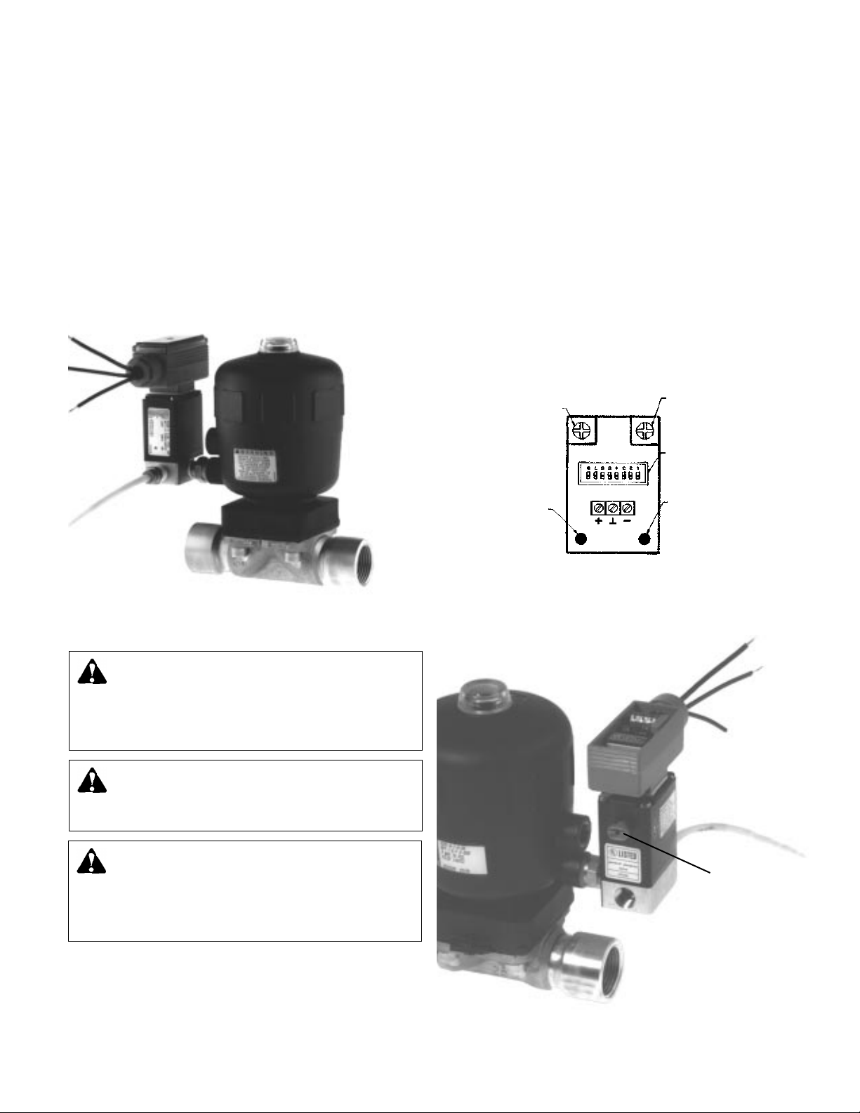
7. Run air for the valve in accordance with local code. Be certain that the minimum and maximum control pressure for
the air are complied with. Purchase a 1/4" air hose adapter,
apply PTFE tape to the threads, and insert into the 1/4" air
port on the side of the solenoid valve as shown in Figure 2.
Then attach tubing.
Timer
OPERATING INSTRUCTIONS
The timer is factory set as follows:
Cycle Time (how often the valve opens): 4 hrs.
Purge Duration (how long valve remains open per cycle): 10 sec
At start-up, the valve can be manually purged by depressing
the button located on the side of the solenoid. (See Figure 4).
We recommend manually purging the valve approximately
every 30 minutes for 2 hours to determine if the factory setting
is sufficient to handle the sediment problem in the system.
Keep in mind that the first hour of start up will typically have a
greater concentration of sediment than that found after several
hours of operation.
If the factory setting is insufficient, adjustment is made by a
series of DIP switches in the timer. The switches are accessed
by removing the cover of the timer. Figure 3 is a sketch of the
timer assembly, and Figure 5 is a diagram of the DIP switches
and the range of settings available.
TIMER CONNECTIONS & ADJUSTMENTS
Valve
Actuator
Pilot Valve
Figure 2
WARNING: Water at temperatures above 100°F
(38°C) can be very hazardous. Piping from valve to
drain should be such that there is no risk of exposure of
hot water to personnel or equipment. Failure to follow
these instructions could result in serious personal injury or
death and property damage.
WARNING: Electrical shock and potential circuit
damage. Disconnect power before beginning installation. Failure to follow these instructions could result in
serious personal injury or death and property damage.
Cycle Time
Potentiometer
Output
Led
Figure 3
Duration of
Purge Time
Potentiometer
Dip
Switches
Power
Led
WARNING: Improper wiring and wire can cause
electrical shock and fires. Wiring connections must
be made in accordance with all applicable electrical codes
and ordinances. Use copper wire only. Failure to follow
these instructions could result in serious personal injury or
death and property damage.
8. Install 120V AC to the timer per local code. Remove the
timer cover to expose the 3 terminal strip. Connect 120V
AC to the terminal strip. Attach the middle terminal to
ground. These connections provide the power for the solenoid and timer. See Figure 3.
2
Manual
Purge
Button
Figure 4
Page 3

t
on
tmin tmax 1 2 3 456 7 8
.5 s 10 s down down down down up down down down
1.5 s 30 s down down up down up down down up
5 s 100 s down up down down up down up down
.5 min 10 min down up up down up down up up
1.5 min 30 min up down down down up up down down
5 min 100 min up down up down up up down up
12 min 240 min up up down down up up up down
.5 h 10 h up up up down up up up up
t
off
CAUTION: Changing the #4 and #5 setting can result
in excessive water loss. Do not change these settings.
Failure to follow this instruction can result in property damage.
POTENTIOMETERS
Figure 5
decrease
cycle
increase
cycle
decrease
purge
increase
purge
As indicated in Figure 5, there are 8 ranges to choose from.
The potentiometers below the DIP switches are used to adjust
the settings within the desired range. DIP switches 1-3 are
used to adjust the duration. DIP switches 6-8 are used to
adjust the cycle. Note that setting of time is proportional, e.g.
8 sec in the .5 s - 10 s range becomes 8 h when changed to
the .5 - 10 h range. Adjustment is as follows:
DANGER: ELECTRICAL SHOCK HAZARD:
Disconnect or otherwise interrupt power to the timer
before programming the unit. Failure to follow these instructions will result in serious personal injury or death.
1. Disconnect or otherwise interrupt power to the timer before
programming the unit.
2. Remove cover of timer (using a screw driver to remove the
screw in the center of the cover).
3. Calculate the percentage of the cycle range required.
4. Change the DIP settings 1-3 and/or 6-8 to a lower range.
5. Adjust potentiometers as labeled in Figure 5 to fine-tune to
desired setting:
Counter clock-wise (CCW) = decrease
min is maximum CCW setting)
(t
Clock-wise (CW) = increase
(t
max is maximum CW setting)
6. Connect the power to the timer and observe the results.
Determine if additional adjustment of the potentiometer is
necessary. If additional adjustment is required then disconnect or interrupt power to the timer and repeat from Step 4,
if not proceed to Step 7.
7. Return DIP settings to desired range.
8. Replace cover on the timer.
9. Supply power to the timer.
EXAMPLE
An example will help illustrate the procedure:
Desired setting: Cycle every 8 hours with 20 sec purge dura-
tion per cycle.
Current factory setting: Cycle every 4 hours with 10 sec purge
duration per cycle.
Step 1: Disconnect or interrupt the power to the timer.
Step 2: Remove the cover to the timer by removing the screw
on the face of the coverplate.
Step 3: 8 hours is 8/10 of the present range.
Step 4: Since settings are proportional, adjustment can be
made in shorter time ranges to enable observation of the
results of the changes in a shorter period of time. Adjust the
cycle time by setting the DIP switches to the .5 s - 10 s range
(6-8 are all set down). Now the valve will cycle every 4 seconds (instead of 4 hours).
Step 5: Adjust the potentiometer located below the 6-8 DIP
switches CW to increase the cycle time to the desired 8 seconds. Turn on the power briefly to confirm that the desired
setting is attained, then disconnect or interrupt the power
before further adjustments are made or before proceeding.
Once complete, set the DIP switches to a range which will
facilitate the setting of the purge duration. In our example, 20
sec falls within the 1.5 s - 30 s range. Since t
max and tmin are
obtained by potentiometer adjustment fully CW and CCW
respectively, adjust the potentiometer under DIP settings 1-3
to a setting between these two values. Turn on the power
briefly to confirm that the desired setting is attained, then disconnect or interrupt the power before further adjustments are
made or before proceeding.
Step 6: Return the cycle time setting to the .5 h - 10 h range
by adjusting the DIP settings 6-8 all up, and the purge setting
to the 1.5 s - 30 s range by adjusting DIP settings 1-3 down,
down and up respectively.
Step 7: Replace cover to the timer.
Step 8: Turn on the power to the timer.
SERVICE INSTRUCTIONS
These valves are designed for sediment service. It is possible,
particularly in abrasive service, that sediment may become
lodged in valve seat upon valve closure which results in leaking. If the valve is leaking, manually purge the valve by depressing the button on the side of the solenoid valve until the water
appears relatively clear. See Figure 4.
Then release your finger from the button to stop the purge. If
leaking continues, this may be a sign that the valve seat is
damaged and in need of replacement. The following is a procedure to replace the diaphragm. Other parts in need of
replacement or repair shall be done at the factory.
3
Page 4

DIAPHRAGM REPLACEMENT (See Figure 6)
WARNING: System fluid under pressure and/or at
high temperature can be very hazardous. Before servicing, reduce system pressure to zero or close the upstream shutoff valve (See No. 4 Installation Instruction
Section). Leave purge valve in open position, and allow
system fluid trapped between the shutoff valve and the
drain to drain completely. Failure to follow these instructions could result in serious personal injury or death and
property damage.
Required parts: EPDM screwed-in diaphragm part no. V57051
1. Turn valve to stand on the cover
18
2. Unfasten the 4 body screws 24
3. Remove body 22 and screws 24
4. Unscrew and remove old/defective diaphragm 21
5. Slightly grease screw threads in the actuator housing 11
(NOTE: use lithium grease ZETGE M 51)
CAUTION: Diaphragm and all diaphragm connecting
parts must be kept free of petroleum based lubricat-
ing fluids and greases.
6. Align the diaphragm with the actuator. Mold seam of diaphragm must be perpendicular to the flow direction.
7. Put body 22 back on. Press down on body to start screws
24 into the actuator thread.
8. Switch actuator on and off twice, fasten screws
24 cross-
wise in unpressurized condition (torque at 5 N-m).
9. Examine valve to make sure it is operating properly and
there are no leaks.
21
20
5
19
18
12
11
1
22
Xylem Inc.
8200 N. Austin Avenue
Morton Grove, Illinois 60053
Phone: (847) 966-3700
Fax: (847) 965-8379
www.xyleminc.com/brands/bellgossett
Bell & Gossett is a trademark of Xylem Inc. or one of its subsidiaries.
© 2012 Xylem Inc. V57050B December 2012
23
24
Figure 6
 Loading...