

Page 1
BELL & GOSSETT
INSTALLED IN THIS LOCATION. IF MISSING, IT MUST BE REPLACED.
INSTRUCTION MANUAL
V51019
WARNING LABEL PART NO. V56871
™
ISO-FLO
Accessories
Installation, Operation, & Service Instructions
INSTALLER: PLEASE LEAVE THIS MANUAL FOR THE OWNER’S USE.
SAFETY
INSTRUCTION
This safety alert symbol will be used in this manual to draw
attention to safety related instructions. When used, the safety
alert symbol means ATTENTION! BECOME ALERT! YOUR
SAFETY IS INVOLVED! FAILURE TO FOLLOW THESE
INSTRUCTIONS MAY RESULT IN A SAFETY HAZARD!
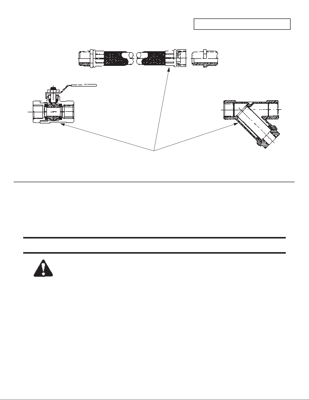
DESCRIPTION
ISO-FLO Accessories includes ball type shutoff valves, inline
Y-type strainers and hook up hoses. Ball Valves are of bronze
construction with TFE seals. Y-Strainers are of bronze construction with a stainless steel strainer. Hoses are EPDM
rubber with a braided stainless steel jacket.
© COPYRIGHT 1996
Bell & Gossett
Morton Grove, IL, U.S.A.
Page 2
OPERATIONAL LIMITS
(These products are designed for use with water or glycol
products only in hydronic systems.)
Accessory Temp ˚F (˚C) Pressure psi (kPa)
Shutoff valves (NPT) 250 (121) 300 (2068.5)
Shutoff valves (sweat) Based on solder type ASTM Std. B16.18
Strainers (NPT) 250 (121) 300 (2068.5)
Strainers (sweat) Based on solder type ASTM Std. B16.18
Hose 1/2" 210 (99) 375 (2585.6)
Hose 3/4" 210 (99) 300 (2068.5)
Hose 1" 210 (99) 290 (2000)
Hose 11/4" 210 (99) 217 (1496)
Hose 11/2 210 (99) 145 (1000)
WORKING PRESSURE & TEMPERATURE LIMITS
(SOLDER TYPE LIMITS FOR ANSI STD. B16.18)
INSTALLATION INSTRUCTIONS
(STRAINERS AND SHUTOFF VALVES)
1. The Shutoff Valves are bi-directional and can be installed in
piping with flow in either direction.
2. The Y-Strainers must be installed with the flow in the direction of the flow arrow on the strainer body.
3. When installing either the shutoff valves or the strainers,
space around the units must be provided to move the valve
handle to the shutoff position and to remove the strainer
from the strainer body for cleaning.
4. The Y-Strainer must be installed with the strainer chamber
down to prevent air binding and also to allow accumulated
dirt to be blown down from the strainer. It is a good idea to
install a blowdown line and a shutoff valve to the strainer Y
connection so that accumulated dirt can be removed.
5. When soldering the sweat type shutoff valves or sweat type
strainer into the piping, make sure that valves are not
heated above 500˚F (260˚C). Wet rags should be used to
keep the valve body temperatures down to prevent damage
from excessive heat.
• Use a torch with a sharp pointed flame.
• Clean tube ends and shutoff valve or strainer connections
thoroughly.
• Use 95-5 (Tin-Antimony), 50-50 or 60-40 (Tin-Lead)
solders only, and a good grade of flux.
Check soldered connections for leaks. Resolder if necessary.
6. For NPT type joints apply pipe compound conservatively to
male connecting fittings only.
Check connections for leaks.
INSTALLATION INSTRUCTIONS
(HOSE ASSEMBLIES)
1. The hose assemblies are supplied with a male NPT pipe
connector on one end and a union coupling and male NPT
adapter on the other end. For
1
/2" through 1" sizes the male
NPT adapter is furnished with a metal to metal joint which
connects to the union coupling. 1
1
/4" and 11/2" sizes are supplied with a fiber gasket instead of a metal to metal joint with
a union coupling.
2. When installing hoses, slack must be provided and the bend
radius must equal or exceed those shown below.
Hose Size Minimum Bend Radius
1
/2" 3" (76.2 mm)
3
/4" 5" (127 mm)
1" 6" (152.4 mm)
1
1
/4" 71/2" (190.5 mm)
1
1
/2" 9" (228.6 mm)
3. Pipe joint compound must be sparingly applied to the male
NPT threads only. Do not apply joint compound to the
adapter threads that mate with the union connector.
4. Hose must not be twisted while it is being installed. The
union joint must be tightened last and it must be held with
two wrenches to prevent the hose from twisting.
2
CAUTION: Excessive use of solder or flux may
result in damage to the shutoff valve seat and ball.
Do not use excessive solder or flux. Failure to follow these
instructions can result in moderate personal injury and/or
property damage.
CAUTION: The use of Teflon impregnated pipe
compound and Teflon tape on pipe threads provides
lubricity. Care should be taken to prevent overtightening
which may damage the shutoff valves or strainers. Failure
to follow these instructions can result in moderate personal injury and/or property damage.
WARNING: Damage to the shutoff valves or strainers
or failure of solder sealing joints may occur if the
solder joint operational limits are exceeded. This can result in water leakage. Failure to follow these instructions
could result in serious personal injury and/or property
damage.
Maximum Maximum
Limitations Limitations
Type of
1
/2" - 1" 11/4" - 11/2"
Solder
Pressure Temp Pressure Temp
psi (kPa) ˚F (˚C) psi (kPa) ˚F (˚C)
95-5 300 (2069) 200 (93) 300 (2069) 175 (79)
Tin- 250 (1724) 225 (107) 250 (1724) 200 (93)
Antimony 200 (1379) 250 (121) 175 (1207) 250 (121)
50-50 and 200 (1379) 100 (38) 175 (1207) 100 (38)
60-40 150 (1034) 150 (66) 125 (862) 150 (66)
Tin-Lead 85 (586) 250 (121) 75 (517) 250 (121)
CAUTION: Heat associated with the use of silver
solder may damage the shutoff valves or the strainers
voiding the warranty. Do not use silver solder. Failure to
follow these instructions can result in moderate personal
injury and/or property damage.
WARNING: These hoses are designed for use with
water and glycol based fluids in hydronic systems.
Do not use hydrocarbon based fluids or other fluids in
these hoses. Failure to follow these instructions could
result in serious personal injury, death and/or property
damage.
WARNING: Hose assemblies may rupture if slack is
not provided or the bend radius is less than required. Make sure that these requirements are provided.
Failure to follow these instructions could result in serious
personal injury, death and/or property damage.
Page 3

3
5. After installation check all joints for leakage and retighten
where necessary.
OPERATING INSTRUCTIONS
(SHUTOFF VALVES)
The ball type shutoff valves will function as a service valve to
isolate hydronic equipment for repairs. To close the shutoff
valves move the formed handle a quarter of a turn until the
handle is perpendicular to the valve and piping.
To return the shutoff valve to the open position move the
formed handle one quarter of a turn until it is inline with the
valve body and system piping.
OPERATING INSTRUCTIONS
(Y-STRAINERS)
If strainer pressure drop becomes excessive accumulated dirt
should be blown down through the blowdown line (if installed)
to a drain. If a blowdown line is not installed see the service
instructions for removing and cleaning the strainer.
SERVICE INSTRUCTIONS
(SHUTOFF VALVES)
Periodically inspect the shutoff valves for signs of corrosion or
leakage. If stem leakage is observed the brass hex packing nut
should be tightened slightly until leak stops. If tightening the
packing nut does not stop the leak or signs of leakage are
noted elsewhere, the shutoff valve must be replaced.
SERVICE INSTRUCTIONS
(Y-STRAINERS)
If excessive pressure drop is noted across the Y-Strainer the
internal strainer has collected a lot of dirt and needs to be
cleaned. If a blowdown line was not installed or if blowing
down the strainer has not solved the pressure drop problem,
the Y-Strainer must be disassembled for cleaning.
To clean the strainer first isolate the Y-Strainer from the system
or drain the system. Allow the system to cool to 100˚F (38˚C).
Leave drains open while servicing the strainer.
Using the appropriate size wrench remove the brass nut on the
Y portion of the strainer. Grasp and remove the strainer. Clean
the strainer in water to remove collected debris. Replace the
strainer nut gasket with a new one. Reinstall the strainer and
the strainer nut. Pressurize the system and check for strainer
gasket leaks. If noted, slightly tighten nut until leakage stops.
Periodically inspect the Y-Strainer for signs of corrosion or
leakage. If corrosion or leakage is noted the Y-Strainer must be
replaced.
SERVICE INSTRUCTION (HOSE ASSEMBLIES)
Periodically inspect the hose for signs of leakage, corrosion or
deterioration of the rubber hose. If noted immediately replace
the hose assembly.
WARNING: Twisted hose assemblies may rupture,
spraying hot and/or pressurized water. Use proper
installation methods to prevent twisting. Failure to follow
these instructions could result in serious personal injury,
death and/or property damage.
WARNING: It is possible, depending on the age or
condition of the shutoff valve stem seal, for some
liquid to escape when closing the valve. Do not have
eyes or face directly above valve. Failure to follow these
instructions could result in serious personal injury.
WARNING: Check for proper sealing when using as
an isolation valve. If the seal is not sealing properly,
liquid will continue to flow from the drain valves. In this
case, the shutoff valve must be isolated from the system
and replaced. Failure to follow these instructions could
result in serious personal injury, death and/or property
damage.
WARNING: Corrosion or leakage are indications
that the shutoff valve may be about to cause serious
damage. The shutoff valve must be replaced. Failure to
follow these instructions could result in serious personal
injury, death and/or property damage.
WARNING: Hot fluids and/or fluids under pressure
are a safety hazard. Do not service the strainer while
it is hot or under pressure. Failure to follow these instructions could result in serious personal injury, death and/or
property damage.
WARNING: Corrosion or leakage are indications
that the Y-Strainer may be about to cause serious
damage. The Y-Strainer must be replaced. Failure to follow these instructions could result in serious personal
injury, death and/or property damage.
WARNING: Corrosion, leakage or deterioration are
indications that the hose assembly may be about to
cause serious damage. The hose assembly must be
replaced. Failure to follow these instructions could result
in serious personal injury, death and/or property damage.
Page 4

PRINTED IN U.S.A. 9-96
AUTHORIZED REPRESENTATIVE
For further information, contact Bell & Gossett, 8200 N. Austin Avenue, Morton Grove, IL
60053, Phone (847) 966-3700 – Facsimile (847) 966-9052.
Bell & Gossett
Morton Grove, IL, U.S.A.
 Loading...