

Page 1
INSTRUCTION MANUAL
Snap Zone™ Valve ½” to 1”
Installation, Operation and
Service Instructions
Installer: Please leave this manual for the owner’s use.
V1000461
Introduction and Safety
Safety message levels
About safety messages
It is extremely important that you read, understand, and follow the safety
messages and regulations carefully before handling the product. They are
published to help prevent these hazards:
• Personal accidents and health problems
• Damage to the product
• Product malfunction
Definitions
Safety message level Indication
DANGER:
WARNING:
CAUTION:
WARNING:
NOTICE:
Product warranty
Coverage
Xylem undertakes to remedy defects in products from Xylem under these
conditions:
• The faults are due to defects in design, materials, or workmanship.
• The faults are reported to a Bell & Gossett representative within the
warranty period
• The product is used only under the conditions described in this manual.
• The monitoring equipment incorporated in the product is correctly
connected and in use.
• All service and repair work is done by Xylem-authorized personnel.
• Genuine Bell & Gossett parts are used.
• Only Ex-approved spare parts and accessories authorized by Xylem are
used in Ex-approved products.
A hazardous situation which, if not
avoided, will result in death or serious injury
A hazardous situation which, if not
avoided, could result in death or serious injury
A hazardous situation which, if not
avoided, could result in minor or
moderate injury
The possibility of electrical risks if
instructions are not followed in a
proper manner
• A potential situation which, if not
avoided, could result in undesirable conditions
• A practice not related to personal
injury
Limitations
The warranty does not cover defects caused by these situations:
• Deficient maintenance
• Improper installation
• Modifications or changes to the product and installation made without
consulting Xylem
• Incorrectly executed repair work
• Normal wear and tear
Xylem assumes no liability for these situations:
• Bodily injuries
• Material damages
• Economic losses
Warranty claim
Xylem products are high-quality products with expected reliable operation and
long life. However, should the need arise for a warranty claim, then contact
your Xylem representative.
Product Description
General description
Snap Zone valves are precision engineered four wire thermoelectrically
operated valves designed for hydronic heating and cooling systems.
WARNING:
California Proposition 65 warning! This product contains chemicals known to the state of California to cause cancer and birth
defects or other reproductive harm.
NOTICE:
This product is not intended for potable water applications.
Features
• Integrated micro switch with floating contact. This switch allows direct
operation of a pump or fan unit.
• Thermoelectric actuator. This actuator opens the snap zone valve when
the thermostat closes, signalling a need for heat. As long as heat is required, the snap zone valve is kept in the open position by a built-in control switch, which meters small amounts of electricity to the actuator.
When the thermostat opens, indicating the need for heat has been satisfied, a return spring in the snap zone valve slowly closes the valve.
Required device
A safety isolating transformer must always be used.
Rule-of-thumb formula:
• p
• n = Number of snap zone valve actuators
transformer
= 6W x n
Page 2
Operational limits
Valve
NPT 32ºF (0ºC) to 212ºF
Snap Zone
Sweat
Maximum Limitations
Temperature ºF (ºC) Max. working pres-
(100ºC) — Fluid
32ºF (0ºC) to 122ºF
(50ºC) — Ambient
sure PSI (kPa)
240 PSI (1655 kPa)
125 PSI (861 kPa)
Install NPT connection
1. Apply pipe compound conservatively to male connecting fittings only.
NOTICE:
Do not overtighten when using PTFE impregnated pipe compound
and PTFE tape on pipe threads. Doing so may damage the
valve body.
2. Check connections for leaks.
1
Install sweat connection
Parameter Value
Operation Normally closed
Voltage 24 V AC/DC +20% / 10%, 0–60
Maximum inrush current 250 mA during 2 min. max.
Operating Current 75 mA
Operating Power 1.8 W
Closing and opening times Approximately 3 minutes
Actuator stroke 4 mm
Switching point Approximately 2 mm
Enclosure rating IP 54
Maximum differential shutoff pressure
Performance Characteristics
Valve size 1/2” 3/4” 1”
Cv 1.8 2.8 2.8
1
Solder type limits for ASTM Std. B16.18 for 95–5 Tin-Antimony Solder
Hz
60 PSI
Installation
Installation precautions
CAUTION:
• Heat associated with the use of silver solder may damage
valve components and void the product warranty. Do not use
silver solder.
• Excessive use of solder or flux may result in damage to the
internal valve components. Do not use excessive solder or
flux.
1. Clean tube ends and valve connections thoroughly with a fine grade
emery cloth or fine grit sandpaper.
2. Adjust the valve to the full open position.
3. Wrap the valve in a cool wet rag.
4. Direct the flame being careful to avoid subjecting the valve to
excessive heat.
5. Allow the valve to cool before touching or operating.
6. Check the soldered connection for leaks.
Install the actuator
NOTICE:
To install an actuator on a valve already in line, close the shutoff valves
(upstream first, then downstream) in the piping or turn off the pump. This
procedure allows the differential pressure in the valve to drop.
1. Make sure that the union connections between the valve and piping
are securely fastened.
2. Thread the actuator adapter onto the valve body.
CAUTION:
• The valve can be damaged if improper sweating (soldering) is
used with the union connection. Before sweating the union
connection to the valve, remove the union nut and O-ring
from the valve body, then sweat the union tailpiece with
union nut into place.
• Make sure that all connecting pipe work is water tight.
• The use of petroleum based lubricants on valve o-rings will
cause swelling and failure of o-rings. This can cause leakage.
Pipe hanging installations
Be aware of water weight in the valve and connected piping when installing
your system.
NOTICE:
Never use the valve as a form of piping support. Support the valves and
piping according to the local building code. Failure to follow these
instructions may result in property damage.
Install the valve
The snap zone valve can be installed horizontally or vertically. Observe the
following precautions:
• When the valve is installed in a vertical position, the electrical
connections must be at the top of the actuator.
• On chilled water applications, the actuator should be above the pipe
centerline.
• Do not install the valve in a dusty area.
1. Install the valve in line via the NPT or sweat union connections.
2. Lubricate the enclosed O-rings with silicone oil or grease before
installation.
3. Insert the O-rings in the grooves that are provided on the mounting
face of each side of the valve.
4. Slide the union nuts over the pipe with the open threaded end of the
nut facing the valve.
5. Thread or sweat the tail pieces for the valve to the adjacent piping.
6. Tighten union nuts to complete valve assembly to line.
3. Press the actuator onto the valve and adapter until it snaps into place.
When assembled, the actuator can be rotated 360º to aid in positioning
of the terminal wires.
Page 3

1
Wiring diagram
1. Thermostat
24V
L1 L2
AC
1
L1LL2NL2
N
2
3
4
5
2. Brown
3. Blue
4. Black
6
5. Gray
6. 24V maximum, 3A ohm
resistive load, 1A inductive
load
Attach insulation
To maximize energy savings, attach insulation to the valve after the system
has been balanced. Tape or other acceptable means can be used to secure
the insulation to the valve. The insulation must not cover the actuator.
Operation
Manual operation instructions
In the case of a power failure follow these instructions:
1. Turn off the power switch that supplies power to the valve.
2. Squeeze the button on the front of the actuator to remove it from the
valve assembly.
3. The valve is now fully open and allows gravity circulation through the
system.
After power is restored, follow these instructions to return the valve to normal
operation:
1. Assemble the actuator to the valve by pressing it back onto the valve
and adapter until it snaps into place.
2. Turn on the power switch.
Remove valve from service
1. Isolate and drain the zone that you wish to service.
2. Turn off the power to the valve actuator.
3. Remove the actuator from the valve by squeezing the button on the
front of the actuator and lifting it up.
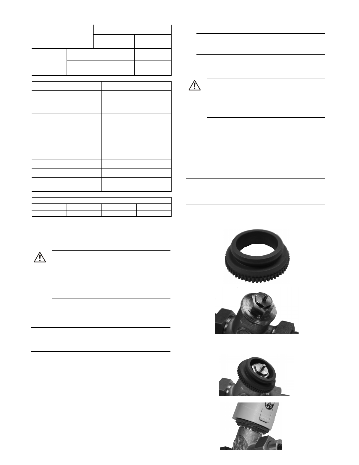
4. Unthread the actuator adapter to reveal the valve bonnet plunger assembly.
5. The following components can now be inspected and replaced if necessary:
Replace the valve body assembly
1. Loosen union nuts on both ends of the valve assembly and carefully
remove the valve from the surrounding piping.
2. Examine the valve body for corrosion or damage. If there is any indication of corrosion or damage, replace the entire body assembly.
3. If there are no signs of damage, replace the O-rings and reinstall the
valve body assembly in the line.
Replace the bonnet plunger assembly
1. With the actuator adapter removed, inspect the valve bonnet plunger
assembly for signs of corrosion, leakage, or damage.
2. Use a wrench to loosen and remove the bonnet plunger assembly.
3. Push the valve stem by hand to verify the motion of the plunger.
The bonnet plunger must be replaced if the plunger does not move,
there is corrosion or other visible damage is seen.
4. Make sure that the male threads of the bonnet plunger assembly and
the female threads of the valve are clean and that there is no debris
present.
5. When installing the replacement bonnet plunger assembly, tighten the
assembly into the valve body until it is finger tight.
6. Tighten the assembly to the following specifications:
Component Seal Torque
Hex bushing packing
box
Bonnet plunger assembly
O-ring 6.0 ft-lbs. + 1.9 ft-
lbs. / 0
O-ring 25.0 ft-lbs. + 7 ft-
lbs. / 0
Maintenance
Precautions
WARNING:
• All procedures must be performed by qualified personnel.
• When the process fluid is hazardous, thermal (hot or cold), or
corrosive, take extra precautions. Employ the appropriate
safety devices and be prepared to control a process media
leak.
• Always wear protective clothing and equipment to safeguard
the eyes, face, hands, skin, and lungs from the particular fluid
in the line.
Valve inspection
Periodically inspect the valve for signs of leakage or corrosion.
WARNING:
Risk for property damage, serious personal injury or death. You
must replace the valve if corrosion or leakage is found.
Valve parts view
The exploded view of the snap zone valve will aid in the performance of
service or maintenance.
NOTICE:
Over application of torque can damage the valve or bonnet plunger assembly.
2
3
1. Valve stem
2. Hex bushing packing box
3. Bonnet plunger assembly
Replace the actuator
If the actuator has failed, it can be replaced rather than replacing the entire valve
assembly. Turn off the power switch that supplies power to the valve.
1. Squeeze the button on the front of the actuator and lift to remove.
2. Disconnect actuator wiring from the power source and any auxiliary
peripherals.
3. Assemble the replacement actuator onto the valve by pressing the actuator onto the valve and adapter until it snaps into place.
4. Follow the wiring procedures in the installation chapter.
Return the valve to service
1. Open the supply to return water to the necessary zones.
2. Open any downstream isolation valves.
3. Vent the system as necessary.
4. Restore power to the actuator.
Page 4

Xylem
1) The tissue in plants that brings water upward from the roots;
2) a leading global water technology company.
We’re 12,500 people unified in a common purpose: creating innovative solutions
to meet our world’s water needs. Developing new technologies that will improve
the way water is used, conserved, and re-used in the future is central to our work.
We move, treat, analyze, and return water to the environment, and we help people
use water efficiently, in their homes, buildings, factories and farms. In more than
150 countries, we have strong, long-standing relationships with customers who
know us for our powerful combination of leading product brands and applications
expertise, backed by a legacy of innovation.
For more information on how Xylem can help you, go to www.xyleminc.com
Xylem Inc.
8200 N. Austin Avenue
Morton Grove, Illinois 60053
Phone: (847) 966-3700
Fax: (847) 965-8379
www.xyleminc.com/brands/bellgossett
Bell & Gossett is a trademark of Xylem Inc. or one of its subsidiaries.
© 2012 Xylem Inc. V1000461 July 2012
 Loading...